
DL-GDTR-01 - Video accessory Proaim - Free user manual and instructions
Find the device manual for free DL-GDTR-01 Proaim in PDF.


| Product Type | Camera Dolly / Action Dolly |
| Model Number | DL-GDTR-01 |
| Brand | Proaim |
| Main Material | Aluminum alloy and steel frame |
| Wheel Type | 16" Pneumatic tires with pull-out ball pins |
| Steering Mechanism | Rear steering handle for 360° rotation; brake lock |
| Seat | Adjustable seat with armrest and back support |
| Floorboard / Platform | Removable side boards and floorboard for varying width |
| Included Accessories | 2x pneumatic wheels, 2x pull-out pins, seat, seat riser, seat arm, speed rail, square extension, knobs, Allen keys (3mm, 4mm), 10 & 13 spanners |
| Adjustable Width | Yes, via push-pin button on round extension and floorboard removal |
| Weight Capacity | Approximately 250 lbs (113 kg) |
| Product Weight | Approximately 22 lbs (10 kg) |
| Dimensions (Assembled) | 55 x 30 x 20 inches (approx.) |
| Warranty | One year from purchase date (parts and labor, excludes shipping and misuse) |
| Compatibility | Universal mounting for cameras via optional head |
| Assembly Required | Yes, detailed assembly manual included |
| Maintenance | Keep wheels inflated, check bolts periodically, lubricate moving parts as needed |
| Cleaning | Wipe with dry cloth; avoid harsh chemicals |
| Safety Features | Wheel brake lock, secure pin mechanisms |
| Country of Origin | China |
Frequently Asked Questions - DL-GDTR-01 Proaim
User questions about DL-GDTR-01 Proaim
0 question about this device. Answer the ones you know or ask your own.
Ask a new question about this device
Download the instructions for your Video accessory in PDF format for free! Find your manual DL-GDTR-01 - Proaim and take your electronic device back in hand. On this page are published all the documents necessary for the use of your device. DL-GDTR-01 by Proaim.
USER MANUAL DL-GDTR-01 Proaim
Gladiator Action Dolly (DL-GDTR-01)
Assembly Manual

natural_image
Black wheeled robotic vehicle with dual monitors and wheels, no visible text or symbolsWhat's In The Box
Please inspect the contents of your shipped package to ensure you have received everything that is listed below.


natural_image
Circular dark object with metallic pins, resembling a disc or cover (no text or symbols visible)Seat

natural_image
Black industrial vehicle with a wheel and attached bracket (no visible text or symbols)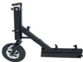
natural_image
Mechanical support structure with a wheel and lever (no text or symbols visible)Left/Right Main Section
2 x 16" Pneumatic Tires
2 x Pull-out wheel ball pin

natural_image
Black adjustable arm handle with a small clip, no text or symbols visible


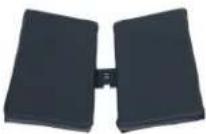
Upper wide Board
Back sport seat
2 x Side Boards Square eKlours Board
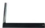
Seat Arm

Seat riser

Knob

(3mm,4mm)Allen key & 10, 2 x 13 Spanner

Speed Rail

Wide round extension
All rights reserved.
No part of this document may be reproduced, stored in a retrieval system, or transmitted by any form or by any means, electronic, mechanical, photo-copying, recording, or otherwise, except as may be expressly permitted by the applicable copyright statutes or in writing by the Publisher.
Action Dolly Setup
- Remove the pull-out wheel ball pin attached to the Pneumatic Tires with the help of your hand.
- Attach the pneumatic wheels with the Right/Left main section and insert the pull-out wheel ball pin.
- Then secure it properly with the pull-out wheel ball pin.
- Slide it open with the help of a push pin button fitted in a wide round extension.
- Then, Loosen the knob of the Pneumatic Wheels.
- Insert the wide round extension in the hole made in the right/left section.

natural_image
Hand holding a black tire with a metallic handle, showing internal blades and a small mechanical component (no text or symbols visible)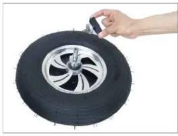
natural_image
Hand adjusting a black tire with a handle, no visible text or symbols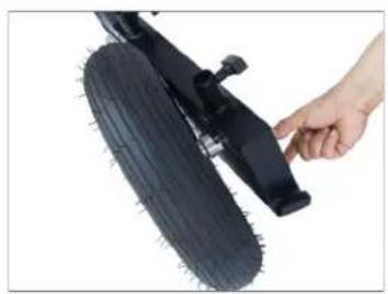
natural_image
Close-up of a hand adjusting a black tire with a handle (no text or symbols visible)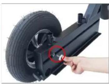
natural_image
Close-up of a hand adjusting a tire component with a red circle highlighting the wheel (no text or symbols visible)
natural_image
Close-up of a hand adjusting a black tire on a vehicle chassis (no text or symbols visible)
natural_image
Close-up of hands holding a white rectangular object against a plain white background (no text or symbols visible)
natural_image
Close-up of hands holding a white cylindrical device with a black handle (no text or symbols visible)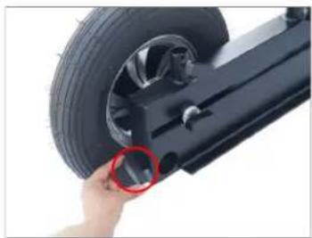
natural_image
Close-up of a hand holding a black bicycle tire with a red circle highlighting the wheel (no text or symbols visible)
natural_image
Close-up of a hand using a tool to adjust the wheel of a vehicle (no text or symbols visible)
natural_image
Close-up of a hand adjusting a car tire mounted on a lift (no visible text or symbols)- Then, loosen the knob on the right/left of the main section.
- Insert the wide round extension on the center part of the main section and tighten it properly with the help of a knob.
- Then attach the wide round extension on the top part of the section by following the same procedure.
- Attach both the left and right main sections together.
- Extend the length of the round extension by pressing the push pin button.
- Insert the side boards matching the holes of the main section.

natural_image
Close-up of a black bicycle support structure with wheels and a hand adjusting the handle (no text or symbols visible)
natural_image
Hand inserting a small black pad into a black metal door (no text or symbols visible)
natural_image
Close-up of a hand adjusting a white plastic lever on a black wheeled scooter (no text or symbols visible)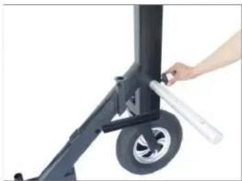
natural_image
Close-up of a hand adjusting a small cylindrical object with a metallic rod, next to a black industrial machine (no visible text or symbols)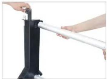
natural_image
Close-up of hands using a white lever mechanism to lift a black mechanical device (no text or symbols visible)
natural_image
Close-up of hands inserting a white cylindrical tube into a black rectangular device (no text or symbols visible)
natural_image
Black three-wheeled scooter with wheels and a hand holding the top (no text or symbols visible)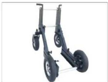
natural_image
Exterior view of a two-wheeled aircraft support system (no text or symbols visible)
natural_image
Person adjusting a large aircraft wing with visible tire and wheel components (no text or symbols)
natural_image
Front view of a two-wheeled vehicle chassis with no visible text or symbols
natural_image
Close-up of hands installing a black plastic component on a tripod stand (no text or symbols visible)
natural_image
Close-up of a hand adjusting a black bicycle seat frame with wheels (no visible text or symbols)- Place both the side boards on top of the main section.
- Attach the floorboard by sliding it on the bottom part of the section.
- Now, Attach the floorboard to the center part following the same process.
- Loosen the Provide knob in the main section.
- Match the main section hole with the seat riser and insert and tighten the seat riser properly.
- Then insert the seat arm matching the hole of the seat riser and secure it properly with the help of its knob.

natural_image
Close-up of a black and silver sports shuttle vane with wheels and suspension components (no text or symbols visible)
natural_image
Close-up of two aircraft landing gear systems with visible wheel and suspension components (no text or symbols)
natural_image
Person assembling a black plastic panel with mechanical arms (no visible text or symbols)
natural_image
Close-up of a person's hand pressing down on a black and white industrial vehicle chassis (no visible text or symbols)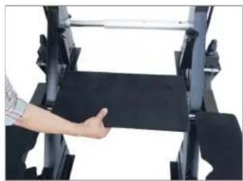
natural_image
Close-up of a hand pressing down on a black fabric or material component (no visible text or symbols)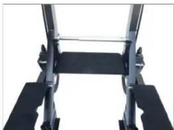
natural_image
Close-up of a black mechanical frame with metal brackets and a horizontal bar (no text or symbols visible)
natural_image
Close-up of a hand adjusting a black mechanical component with a small connector (no visible text or symbols)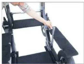
natural_image
Person using a mechanical device on a black platform (no visible text or symbols)
natural_image
Close-up of a person adjusting or adjusting a black aircraft landing gear with visible tare (no text or symbols)
natural_image
Close-up of a hand adjusting a black mechanical frame with a handle (no visible text or symbols)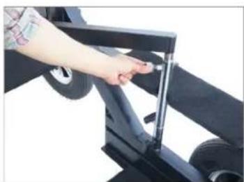
natural_image
Close-up of a hand adjusting a black mechanical frame with wheels and a vertical rod (no visible text or symbols)- Finally, the seat riser or seat arm is properly attached to the dolly.

natural_image
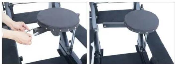
Front view of a black wheeled vehicle chassis with wheels and support brackets (no visible text or symbols)- Remove the bolt in the seat arm with the help of a spanner and 4mm Allen key.

natural_image
Two-step photo showing hands using a tool to adjust or install a mechanical component, no visible text or symbols- Insert the seat into the seat arm and secure the seat properly with the help of its knob.

natural_image
Two-panel image showing a person adjusting a black exercise chair frame with a hand adjusting the seat (no text or symbols visible)- Then insert the seat arm bolt into the seat arm.

natural_image
Close-up of hands adjusting a black bicycle seat frame with a tool, no visible text or symbols- Then Tighten Properly with The Help of a Spanner And 4mm Allen Key.
natural_image
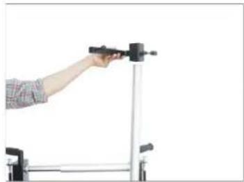
Two-panel image showing a hand using a tool to adjust a circular mechanical component, with no visible text or symbols.- Insert the speed rail into the side hole of the main section, and tighten it properly with the help of a knob.

natural_image
Two-panel image showing a person adjusting a black exercise machine frame, no text or symbols visible- Insert the square extension by sliding it into the speed rail and secure it with the extension knob by setting the position.
- Attach the back support seat to the square extension and tighten both the bolts of the back support seat with a 4mm Allen key.
- Insert the speed rail into the hole of the back-side of the main section and secure it properly with a knob.
natural_image
Person using a handheld device to lift a metal frame (no text or symbols visible)
natural_image
Hand adjusting a metal bracket with a black handle (no text or symbols visible)
natural_image
Close-up of hands holding a black electronic device with a bracket (no visible text or symbols)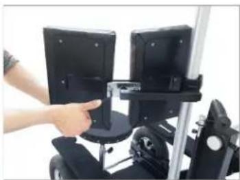
natural_image
Person using a handheld device to lift a black monitor (no visible text or symbols)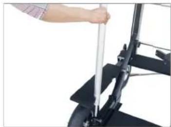
natural_image
Close-up of a person using a vertical tool on a bicycle (no visible text or symbols)
natural_image
Close-up of a hand adjusting a tire on a stationary exercise machine (no text or symbols visible)
natural_image
Side view of a black wheeled vehicle with wheels and a mounted sensor array (no visible text or symbols)- Pulling the rear steering will cause the wheels on the main section to rotate 360° or, releasing it will lock the wheel again.
- Manually lock and unlock the wheel brake of the main section with the help of a hand. As shown in the image.

natural_image
Close-up of a hand adjusting a metal lever handle with a black lever (no text or symbols visible)
natural_image
Close-up of a hand adjusting a black mechanical component with a metallic clip (no text or symbols visible)
natural_image
Close-up of a hand adjusting a car tire with a mechanical clamp (no visible text or symbols)
natural_image
Close-up of a hand adjusting a tire on a car tire mounted on a lift (no visible text or symbols)- To narrow the size of the dolly, remove the floorboard.
- Try using the push-pin button of the wide round extension, which will convert the size of the dolly to a slightly narrower size.
- After collapsing the round extension, slide the floor board and insert it, as shown in the image.

YOUR PROAIM GLADIATOR ACTION DOLLY ALL DRESSED UP AND READY TO GO!

natural_image
Black and white photo of a wheeled robotic vehicle with wheels and a mounted camera frame (no visible text or symbols)(SHOWN WITH OPTIONAL ACCESSORIES)
Warranty: We offer one year warranty for our products from date of purchase. Within this period of time, we will repair it without charge for labor or parts. Warranty doesn't cover transportation costs nor does it cover a product subjected to misuse or accidental damage. Warranty repairs are subjected to inspection and evaluation by us.
Liability: We are not liable for damage caused by products that we do not supply or from mishandling in transit, accident, misuse, neglect, lack of care of the product, or service by anyone other than our company.
Contact Us: In case of any kind of dissatisfaction, please Contact us immediately and we promise our utmost support and care until you use our product.

Brand : Proaim
Model : DL-GDTR-01
Category : Video accessory