Stealth ST5.1300D - Receiver Soundstream - Free user manual and instructions
Find the device manual for free Stealth ST5.1300D Soundstream in PDF.


| Type | Car Audio Amplifier |
| Number of Channels | 5 |
| Max Power Output | 1300W |
| RMS Power (per channel) | 4 x 50W + 1 x 300W (4 ohms) |
| Frequency Response | 20Hz - 20kHz |
| Dimensions (W x L x H) | 7.5 x 2.5 x 12 inches |
| Weight | 5.5 lbs |
| Power Supply Voltage | 12V DC |
| Input Sensitivity | 200mV - 6V |
| Crossover Type | Variable low-pass and high-pass |
| Bass Boost | 0-12dB at 45Hz |
| Remote Control | Included wired remote |
| Signal-to-Noise Ratio | >100dB |
| Total Harmonic Distortion | <0.05% |
| Fuse Rating | 80A (external) |
| Protection Features | Thermal, short circuit, overload |
| Cooling | Convection with heatsink |
| Mounting | Ventilated location recommended |
| Care Instructions | Wipe with dry cloth only |
| Safety Cautions | Disconnect battery before wiring |
Frequently Asked Questions - Stealth ST5.1300D Soundstream
User questions about Stealth ST5.1300D Soundstream
0 question about this device. Answer the ones you know or ask your own.
Ask a new question about this device
Download the instructions for your Receiver in PDF format for free! Find your manual Stealth ST5.1300D - Soundstream and take your electronic device back in hand. On this page are published all the documents necessary for the use of your device. Stealth ST5.1300D by Soundstream.
USER MANUAL Stealth ST5.1300D Soundstream
Congratulations on the new amplifier!
Thank you for your decision to purchase a STEALTH Series mobile amplifier! Our Amplifiers are the result of extensive engineering, testing, and bulletproof construction. Their versatility enables compatibility with optional signal and audio processors. These high quality MOSFET amplifiers may be configured to allow maximum flexibility in designing different types of speaker systems.
Digital Micro Class D Premium Technology
The STEALTH Series are high quality MOSFET amplifiers that are capable of running a system full range, or they may be selected only to power subwoofers. It is important that you closely follow the wiring instructions contained in this Owners Manual so that you get the most from your STEALTH Series mobile amplifier.
Caution, Read First
Some of our amplifiers are capable of producing a sound pressure level that can cause permanent damage to your hearing system. High sound pressure levels combined with long time listening can give permanent damage to your hearing system. Choose a listening level that is comfortable for your ear. To establish a safe level: Start your volume control at a low setting. Slowly increase the volume until you can hear the music comfortably and clearly, without any distortion. Sudden sound shocks are dangerous.
TECHNICAL FEATURES
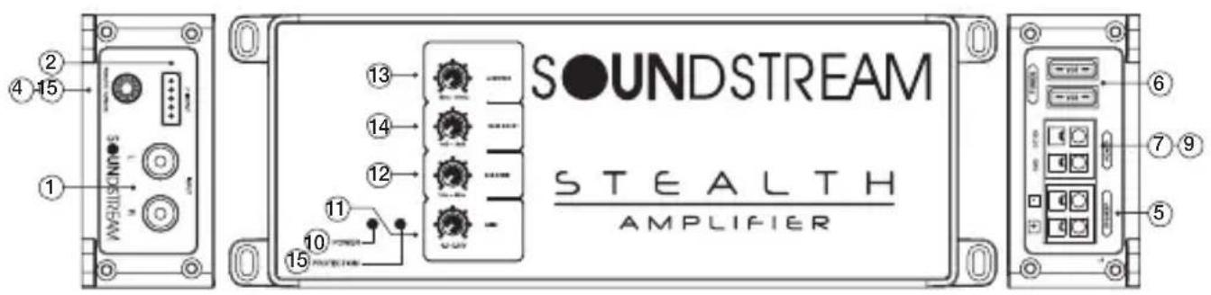
ST1.1000D
- Premium High-Efficiency Class D Monoblock Subwoofer Amplifier
- Micro 3" x 8" Chassis Design Accommodates Any Application
• Hybrid Aluminum Alloy Heatsink for Optimum Heat Dissipation
• 2-ohm Mono Minimum Impedance Stability
• MOSFET Power Supply w/Audiophile Grade IRTM Transistors
• Military Grade SMT PCB Maintains Dynamic Performance - Direct Short, Thermal, & Overload Circuits Protect Amplifier
- 500mV-12V Low-Level RCA or High Level Signal Input
- Quick Disconnect RCA & High-Level Wire Harnesses
- Quick Disconnect Power and Speaker Output Harnesses
- Top-Mount Crossover Controls for Easy After-Install Access
• Variable 12dB Low Pass & Subsonic Crossover Filter
• 18dB Bass Boost Increases Low Octave Harmonics
• 12dB Subsonic Crossover Blocks Harmful Frequencies - Dash Mount Subwoofer gain Control Module Included
• 350w x 1 @ 4-ohm Mono - 500w x 1 @ 2-ohm Mono
• 50-500Hz Variable Low Pass Crossover
• 10-50Hz Variable 12dB Subsonic Crossover
• 0-18dB Variable 45Hz Bass Boost - Dimensions: 3"w x 1.50"h x 8"l
ST2.1000D
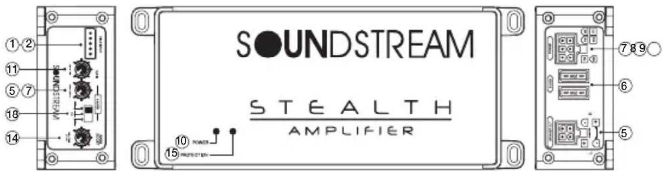
- Premium High-Efficiency Class D Tow Channel Stereo Amplifier
- Micro 3" x 6" Chassis Design Accommodates Any Application
• Hybrid Aluminum Alloy Heatsink for Optimum Heat Dissipation
• 2-ohm Stereo & 4-ohm Bridged Impedance Stability
• MOSFET Power Supply w/Audiophile Grade IRTM Transistors
• Military Grade SMT PCB Maintains Dynamic Performance - Direct Short, Thermal, & Overload Circuits Protect Amplifier
- 500mV-12V Low-Level RCA or High Level Signal Input
- Quick Disconnect RCA & High-Level Wire Harnesses
- Quick Disconnect Power and Speaker Output Harnesses
• Variable 12dB High Pass & Low Pass Crossover Filter
• 18dB Bass Boost Increases Low Octave Harmonics
• 140w x 2 @ 4-ohm Stereo
• 250w x 2 @ 2-ohm Stereo - 500w x 1 @ 4-ohm Bridged
• 50-500Hz Variable High Pass Crossover
• 50-500Hz Variable Low Pass Crossover
• 0-18dB Variable 45Hz Bass Boost - Dimensions: 3"w x 1.50"h x 6" l
ST3.1000D
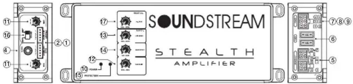
• Premium High-Efficiency Class D Three Channel Stereo Amplifier
- Micro 3" x 8" Chassis Design Accommodates Any Application
- Hybrid Aluminum Alloy Heatsink for Optimum Heat Dissipation
• 2-ohm Stereo & 4-ohm Bridged Stability For Speaker Channel
• 2-ohm Mono Minimum Impedance for Subwoofer Channel
• MOSFET Power Supply w/Audiophile Grade IRTM Transistors
• Military Grade SMT PCB Maintains Dynamic Performance
- Direct Short, Thermal, & Overload Circuits Protect Amplifier
- 500mV-12V Low-Level RCA or High Level Signal Input
- Quick Disconnect RCA & High-Level Wire Harnesses
- Quick Disconnect Power and Speaker Output Harnesses
- Top-Mount Crossover Controls for Easy After-Install Access
• Variable 12dB High Pass & Low Pass Crossover Filter
• 18dB Bass Boost Increases Low Octave Harmonics
• 12dB Subsonic Crossover Blocks Harmful Frequencies
- Dash Mount Subwoofer gain Control Module Included
- 65w x 2 @ 4-ohm Stereo + 200w x 1 @ 4-ohm Mono
- 100w x 2 @ 2-ohm Stereo + 300w x 1 @ 2-ohm Mono
- 200w x 1 @ 4-ohm Bridged + 300w x 1 @ 2-ohm Mono
• 50-500Hz Variable High Pass Crossover (ch. 1 & 2)
• 50-500Hz Variable Low Pass Crossover (ch. 3)
• 10-50Hz Variable12dB Subsonic Crossover (ch. 3)
• 0-18dB Variable 45Hz Bass Boost (ch. 3)
• Dimensions: 3"w x 1.50"h x 8"1
ST4.1200D
• Premium High-Efficiency Class D Four Channel Stereo Amplifier
- Micro 3" x 8" Chassis Design Accommodates Any Application
• Hybrid Aluminum Alloy Heatsink for Optimum Heat Dissipation
• 2-ohm Stereo & 4-ohm Bridged Impedance Stability
• MOSFET Power Supply w/Audiophile Grade IRTM Transistors
• Military Grade SMT PCB Maintains Dynamic Performance
- Direct Short, Thermal, & Overload Circuits Protect Amplifier
- 500mV-12V Low-Level RCA or High Level Signal Input
- Quick Disconnect RCA & High-Level Wire Harnesses
- Quick Disconnect Power and Speaker Output Harnesses
- Top-Mount Crossover Controls for Easy After-Install Access
• Variable 12dB High Pass & Low Pass Crossover Filter
• 100w x 4 @ 4-ohm Stereo
• 150w x 4 @ 2-ohm Stereo
• 300w x 2 @ 4-ohm Bridged
• 50-500Hz Variable High Pass Crossover
• 50-500Hz Variable Low Pass Crossover
- Dimensions: 3"w x 1.50"h x 8"1
ST5.1300D
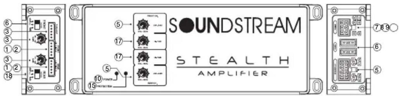
• Premium High-Efficiency Class D Five Channel Stereo Amplifier
- Micro 3 ^1 x 10 ^1 Chassis Design Accommodates Any Application
• Hybrid Aluminum Alloy Heatsink for Optimum Heat Dissipation
• 2-ohm Stereo & 4-ohm Bridged Impedance Stability
- MOSFET Power Supply w/ Audiophile Grade IR ^TM Transistors
• Military Grade SMT PCB Maintains Dynamic Performance
- Direct Short, Thermal, & Overload Circuits Protect Amplifier
- 200mV-12V Low-Level RCA or High Level Signal Input
- Quick Disconnect RCA & High-Level Wire Harnesses
- Quick Disconnect Power and Speaker Output Harnesses
- Top-Mount Crossover Controls for Easy After-Install Access
• Variable 12dB High Pass Crossover Filters (ch. 1-4)
• Variable 12dB Low Pass Crossover Filter (ch.5)
• Variable 12dB Subsonic Crossover Filter (ch.5)
• Variable 18dB 45Hz Bass Boost (ch.5)
- Swithable Phase Shift (ch.5)
- Dash Mount Subwoofer Gain Control Module Included
- 60w x 4 + 220w x 1 @ 4-ohm Stereo
- 90w x 4 + 300w x 1 @ 2-ohm Stereo
- 50-500Hz Variable High Pass Crossover (ch.1-4)
• 50-500Hz Variable Low Pass Crossover (ch.5)
• 10-50Hz 12dB Subsonic Crossover (ch.5)
• 0-18dB 45Hz Bass Boost (ch.5)
• 0-180 Degree Phase Shift
• Dimensions: 3w x 1.50h x 10l
INSTALLATION PRECAUTIONS

STALLATION PRECAUTIONS
NOTE: Proceed only if you are qualified installer otherwise, let your dealer do it. Always wear protective eyewear when using tools.
- Turn off all stereo and other electrical devices before you begin.
- Disconnect the negative(-) lead from your vehicles battery.
Make sure there is at least 2-inches (5 cm) around the air vents on the amplifier. - When connecting ground points, make sure all paint is carefully scrapped away from *The auto body and contact is made with bare metal.
- Use a utility knife to trim away fabric from hole locations before drilling or cutting.
- When running power cables through sheet metal, be sure to use grommets to properly insulate the metal edges from the wire insulation.
- If possible, use tubing through grommets.
MOUNTING THE AMPLIFIER

To keep your STEALTH Series amplifier running at top performance, choosing the proper location it of utmost importance. For this reason the amplifier should be mounted in a location which will allow air to circulate freely. A clearance of at least 2-inches (5 cm) to all sides of the amplifier is necessary not only for proper cooling, but also for gaining access to the inputs and other variable controls. Be sure that the power and signal cable connections can enter and leave the amplifier in a straight line to avoid the risk of kinked wires causing a malfunction.

MOUNTING LOCATION
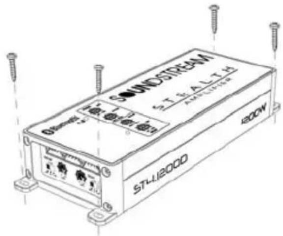
Your STEALTH Series amplifier comes with mounting feet that need to be attached to the amplifier prior to installation. Once the feet are in place, use the amplifier as a template and mark the four screw locations. Use caution to make sure there are no objects behind the installation surface that may become damaged during drilling. The amplifier should be protected from exposure to moisture and direct sunlight. The best places to mount your amplifier are: The floor of the trunk, under the driver's seat, or on the back of the rear seat. For alternate installation locations.
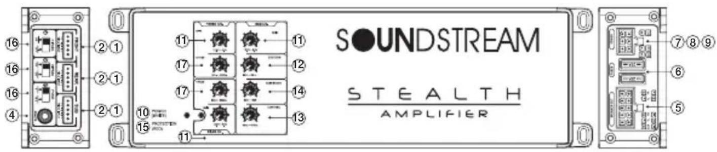
1. LINE IN (RCA)
The RCA style input jacks are for use with source units that have RCA line level outputs.
A source unit with a minimum of 250mV is required for proper operation.
However, this input will accept levels up to 6Vrms.
2. High Level Input
If you are installing by using a high level. you do not need to connect to the remote. To hear a better sound quality, you must connect the high level ground wire to the head-unit ground.
3. Thru-Out
The LINE OUT allows you to build multiple amplifiers systems without having to use splitter cords to distribute the signal. Now it is simply a matter of bringing one set of RCAS into the fist amplifier, then using the line out RCA jacks as the feed to the next amplifier.
4. Remote Bass Boost Control
This control adjusts the Bass Boost gain for the amplifier
*Packed product can be different from the photograph.
5. SPEAKER Coneector.
As shown in the wiring diagrams, be sure to observe speaker polarity through the system and speaker impedance. This specially tooled terminal is designed to accommodate p to 18 gauge speaker wire.
6. FUSE
For convenience all A STEALTH Series amplifiers utilize common automotive ATC type fuses. For continued protection in the event that a fuse blows, replace the fuse only with the same value.
7. Power Input Connector
This terminal is the main power input for the amplifier and must be connected directly to the positive (+) terminal of the car battery.
8. Remote (Remote Input Connection)
All STEALTH Series amplifiers can be turned on by applying 12 volts to this terminal. This can be found on the rear of the source unit in the form of an electric antenna output, or a remote output.
If this is not available you can wire to the ACC position on the key. An 18 gauge wire is sufficient to run the REMOTE.
9. GND (Ground Input Connection)
A good quality ground is required for your STEALTH Series amplifier to operate at peak performance.
A short length of cable the same gauge as your power cable should be used to attached the ground terminal directly to the chassis of the vehicle.
10.Power Indicator
The GREEN when the power is on.
11. Gain Adjustment Control
The input level can be adjusted with this control. Turn it in the clockwise direction when the output level of the car audio unit seems low
12. Sub Sonic Filter
Variable subsonic filter (20Hz \~50Hz)
The subsonic filter will roll off all of the unwanted frequencies below 20HZ \~50Hz.
This will allow the amplifier to use that wasted power on the audible bandwidth.
13. Low Pass Filter
STEALTH amplifier has an internal variable low pass filter. It can be set from 50 p to 500Hz.
14. Bass boost level control
Turn this control to boost the frequencies around 45Hz to a maximum of 12dB.
15. Protection Indicator
When the PROTECTOR is activated, the indicator lights in red. When the PROTECTOR
Is activated refer to the Troubleshooting Guide. (PPI Logo Badge)
16. High Pass ON/OFF Selector Switch
When the switch is in the ON position, the filter is set to High-pass. it is activated High pass potentiometer control.
17. High Pass Filter
STEALTH amplifier has an internal variable High pass filter. It can be set from 50 up to 500 Hz. It also has that can be set from 500 up to 5KHz.
18. High Pass/Full/Low Pass Selector Switch
It is activated in each of the positions in top control.
[]

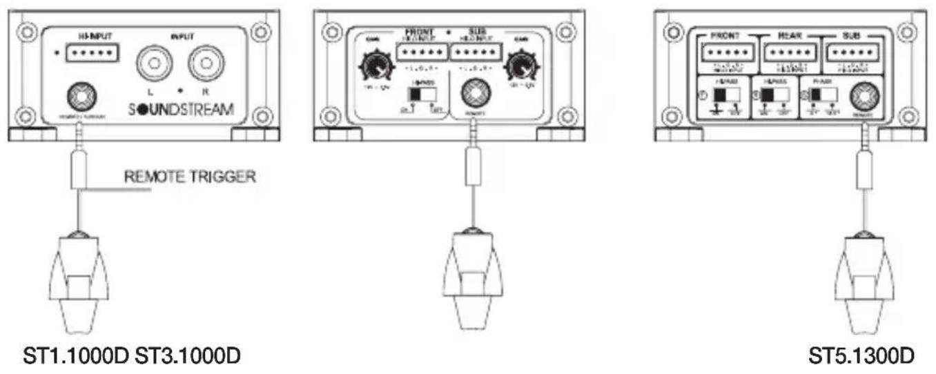
Remote Subwoofer Level Control
This input allows you to add remote that will allow you to control the subwoofer output of your STEALTH amplifier from your dashboard. and to adapt the amplifier to all kind of signal sources with varying levels there are a level control provided on the amplifier next to the phone jacks. It should not be used as volume controls. Start with a "12' clock" setting of the level controls. If you set the head unit volume to 75% of maximum you should achieve a good sound without distortion. Find a point of the level setting where the distortion is just discernible. At this point slightly reduce the control.

How to Installation
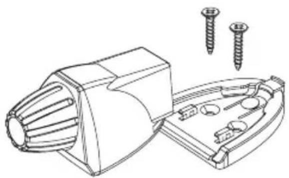
The dash control mounts with two screws, which attach to the underside of the dashboard. Slide under the dash and place the dash control in its mounting position, mark the two mounting holes, drill pilot holes, and secure with two screws.
natural_image
Technical line drawing of a mechanical component with screws and screw holes (no text or symbols)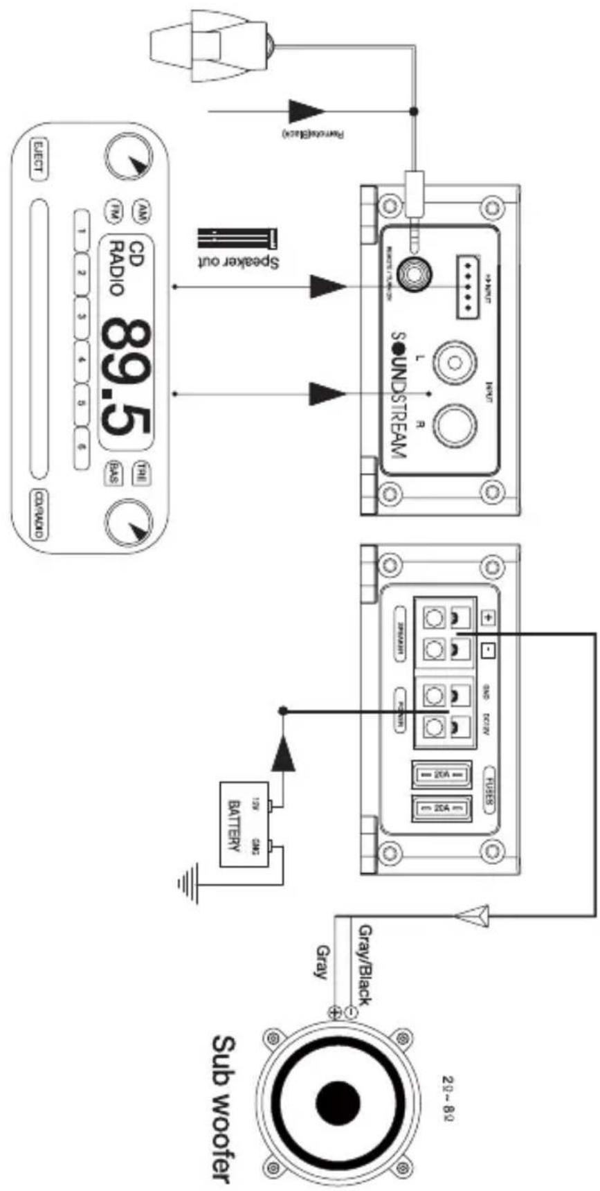
STL.1000
ST2.10001 Channel Mode (4Ω\~8Ω)
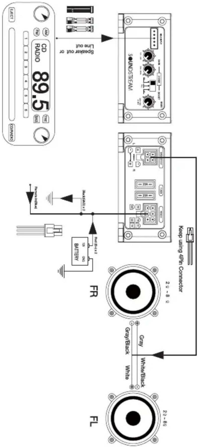
flowchart
graph TD
    A["FL"] -->|29-89 White/Black| B["FR"]
    B -->|Gray/Black White| C["20-89"]
    C --> D["Battery"]
    D --> E["Radio 1x2"]
    E --> F["CD Radio 89.5"]
    F --> G["Speaker out or Line out"]
    G --> H["sound streaming"]
    H --> I["Line OUT"]
    I --> J["Audio/Black"]
    style A fill:#f9f,stroke:#333
    style B fill:#f9f,stroke:#333
    style C fill:#f9f,stroke:#333
    style D fill:#ccf,stroke:#333
    style E fill:#ccf,stroke:#333
    style F fill:#ccf,stroke:#333
    style G fill:#ccf,stroke:#333
    style H fill:#ccf,stroke:#333
    style I fill:#ccf,stroke:#333
    style J fill:#ccf,stroke:#333
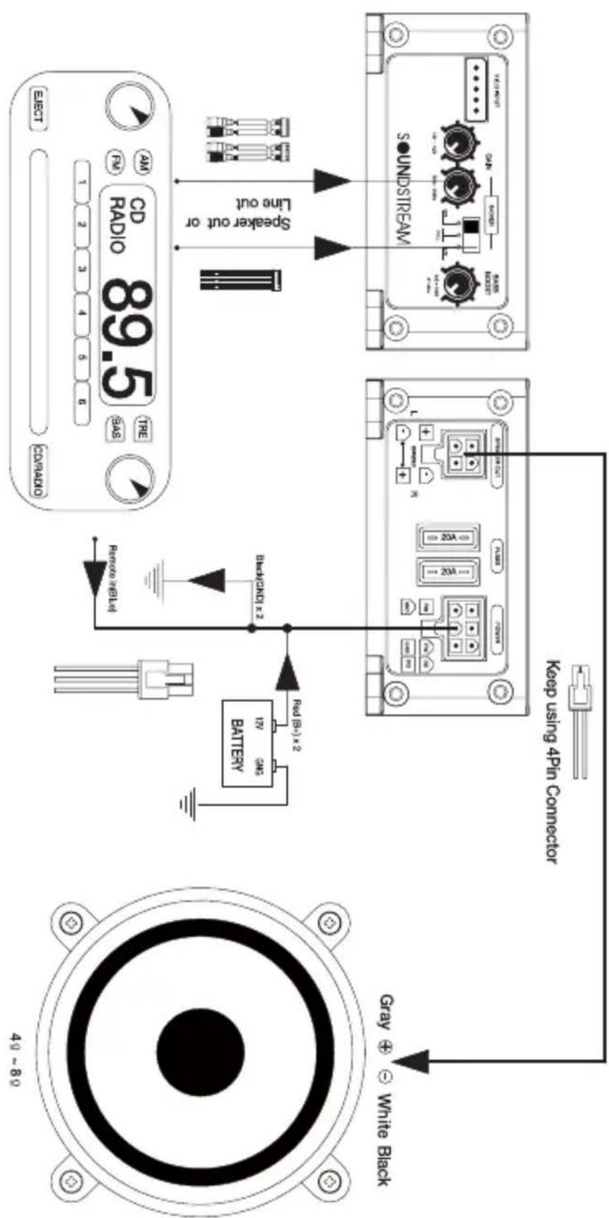
ST2.10001 4 channel Mode (4Ω\~8Ω)
flowchart
graph TD
    A["Speaker out or Line out"] --> B["CD Radio 89.5"]
    B --> C["Subwoofer"]
    C --> D["Gray/Black"]
    D --> E["Gray"]
    E --> F["White/Black"]
    F --> G["Gray/Black"]
    G --> H["20 - 8"]
    H --> I["20 - 8"]
    I --> J["Gray/Black"]
    J --> K["White/Black"]
    K --> L["20 - 8"]
    L --> M["Gray/Black"]
    M --> N["Gray/Black"]
    N --> O["40 - 8"]
    O --> P["Subwoofer"]
    P --> Q["Gray/Black"]
    Q --> R["Gray/Black"]
    R --> S["20 - 8"]
    S --> T["Gray/Black"]
    T --> U["20 - 8"]
    U --> V["Gray/Black"]
    V --> W["20 - 8"]
    W --> X["Gray/Black"]
    X --> Y["20 - 8"]
    Y --> Z["Gray/Black"]
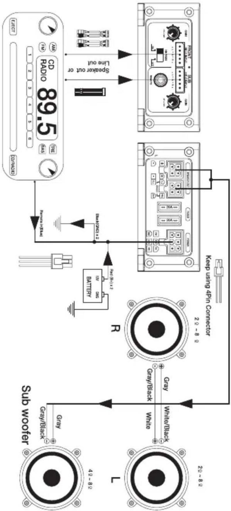
ST3.10001 3 channel Mode (4Ω\~8Ω)
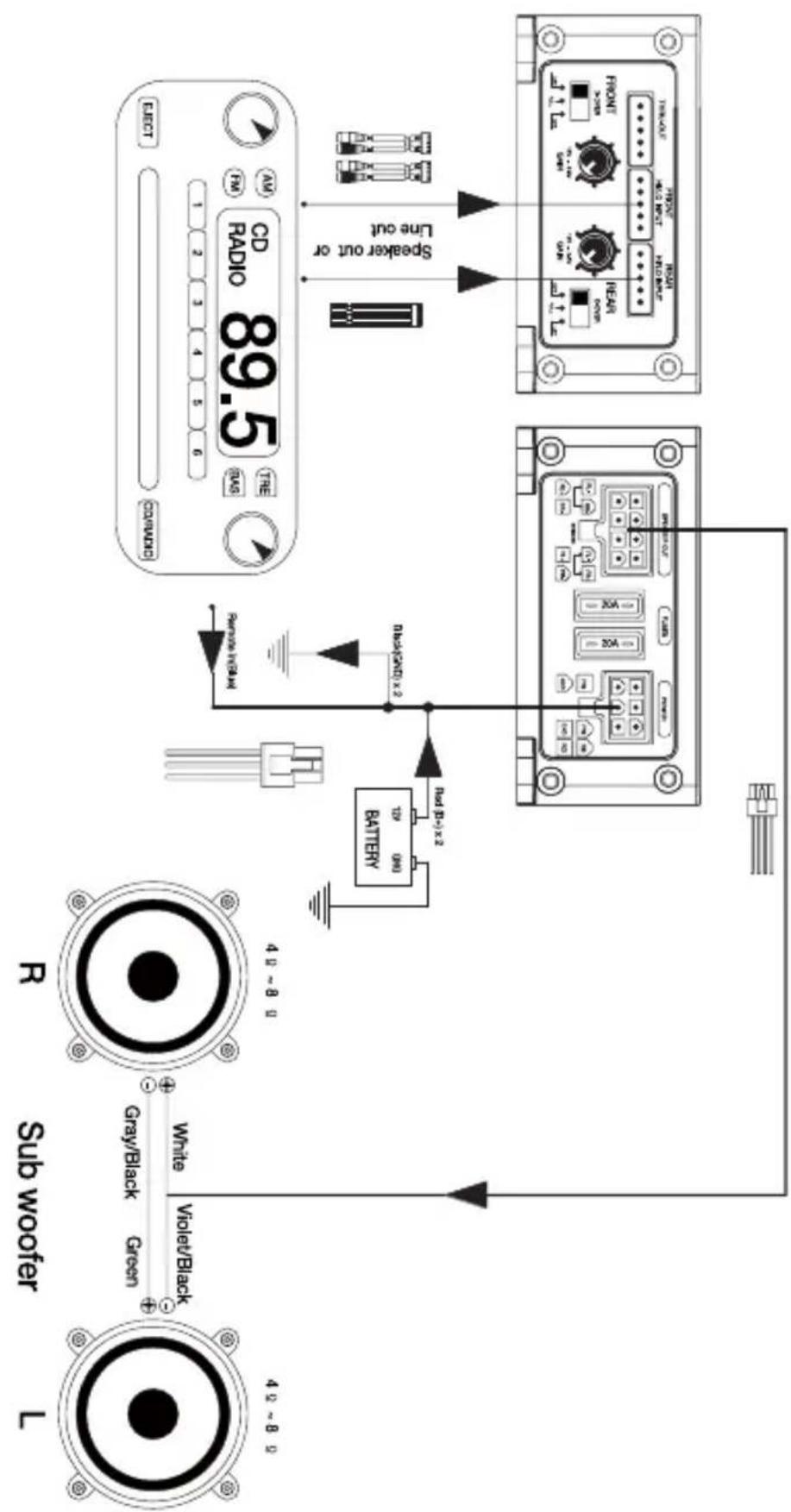
flowchart
graph TD
    A["4.5 ~ 8.5"] --> B["Sub woofer L"]
    B --> C["Gray/Black Green"]
    C --> D["White"]
    D --> E["Violet/Black"]
    E --> F["Battery"]
    F --> G["Red 12P-3 x 2"]
    G --> H["Red/6500x 3"]
    H --> I["Speaker out or Line out"]
    I --> J["CD Radio 89.5 Display"]
    J --> K["Back to Subwoofer R"]
    K --> L["Green Cable"]
    L --> M["Red 12P-3 x 2"]
    M --> N["Red/6500x 3"]
    N --> O["Speaker out or Line out"]
ST4.12001 2 channel Mode (4.8\~8.8)
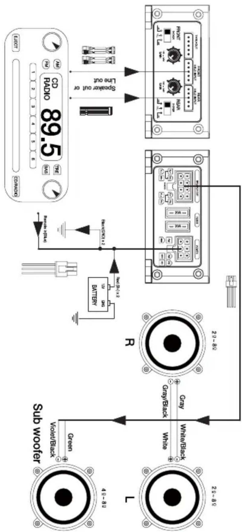
flowchart
graph TD
    A["Speaker out or Line out"] --> B["Radio 89.5"]
    B --> C["Subwoofer"]
    C --> D["Green"]
    D --> E["Violet/Black"]
    E --> F["Gray/Black"]
    F --> G["White/Black"]
    G --> H["20~80"]
    H --> I["Gray/Black"]
    I --> J["White/Black"]
    J --> K["20~80"]
    K --> L["Battery"]
    L --> M["Battery 12V 200Ω"]
    M --> N["Switch 40-10 x 2"]
    N --> O["Switch 30-10 x 2"]
    O --> P["Switch 20-10 x 2"]
    P --> Q["Switch 10-10 x 2"]
    Q --> R["Switch 5-10 x 2"]
    R --> S["Switch 3-10 x 2"]
    S --> T["Switch 2-10 x 2"]
    T --> U["Switch 1-10 x 2"]
    U --> V["Switch 5-10 x 2"]
    V --> W["Switch 3-10 x 2"]
    W --> X["Switch 2-10 x 2"]
    X --> Y["Switch 1-10 x 2"]
    Y --> Z["Switch 5-10 x 2"]
ST4.1200D 3 channel Mode (2Ω\~8Ω)
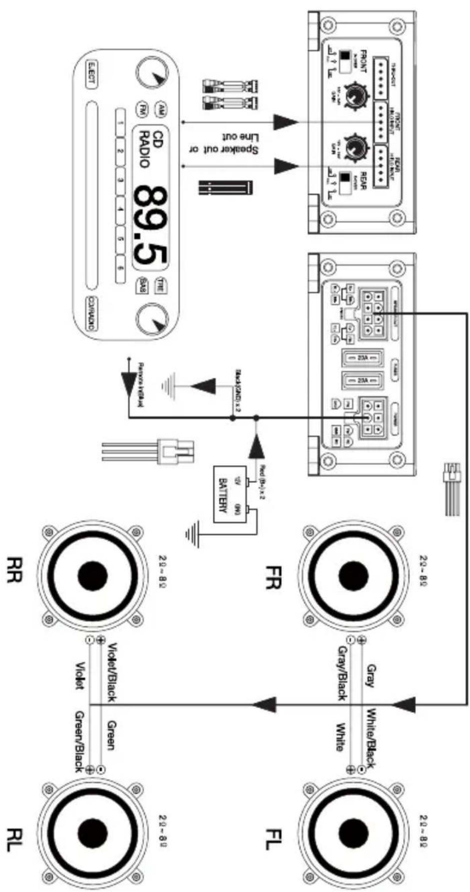
flowchart
graph TD
    A["Speaker out or Line out"] --> B["Line OUT"]
    B --> C["Battery"]
    C --> D["Radio 89.5"]
    D --> E["Display"]
    F["Blue/Risk Range"] --> G["Green/Black"]
    G --> H["Violet/Black"]
    H --> I["White/Black"]
    I --> J["Gray/Black"]
    J --> K["White/Black"]
    K --> L["Blue/Risk Range"]
    M["Black Label"] --> N["Red (40) x 2"]
    O["Red Label"] --> P["Red (40) x 2"]
    Q["Red Label"] --> R["Red (40) x 2"]
    S["Red Label"] --> T["Red (40) x 2"]
    U["Red Label"] --> V["Red (40) x 2"]
    W["Red Label"] --> X["Red (40) x 2"]
    Y["Red Label"] --> Z["Red (40) x 2"]
    AA["Red Label"] --> AB["Red (40) x 2"]
    AC["Red Label"] --> AD["Red (40) x 2"]
    AE["Red Label"] --> AF["Red (40) x 2"]
    AG["Red Label"] --> AH["Red (40) x 2"]
    AI["Red Label"] --> AJ["Red (40) x 2"]
    AK["Red Label"] --> AL["Red (40) x 2"]
    AM["Red Label"] --> AN["Red (40) x 2"]
    AO["Red Label"] --> AP["Red (40) x 2"]
    AQ["Red Label"] --> AR["Red (40) x 2"]
    AS["Red Label"] --> AT["Red (40) x 2"]
    AU["Red Label"] --> AV["Red (40) x 2"]
    AW["Red Label"] --> AX["Red (40) x 2"]
    AY["Blue/Risk Range"] --> AZ["Green/Black"]
    BA["Blue/Risk Range"] --> BB["Violet/Black"]
    BC["Blue/Risk Range"] --> BD["Violet/Black"]
    BE["Blue/Risk Range"] --> BF["Violet/Black"]
    BG["Blue/Risk Range"] --> BH["Violet/Black"]
ST4.1200D 4 Channel Mode (4.8\~8.8)
Thru-Out Hi-level & Low Level Connection
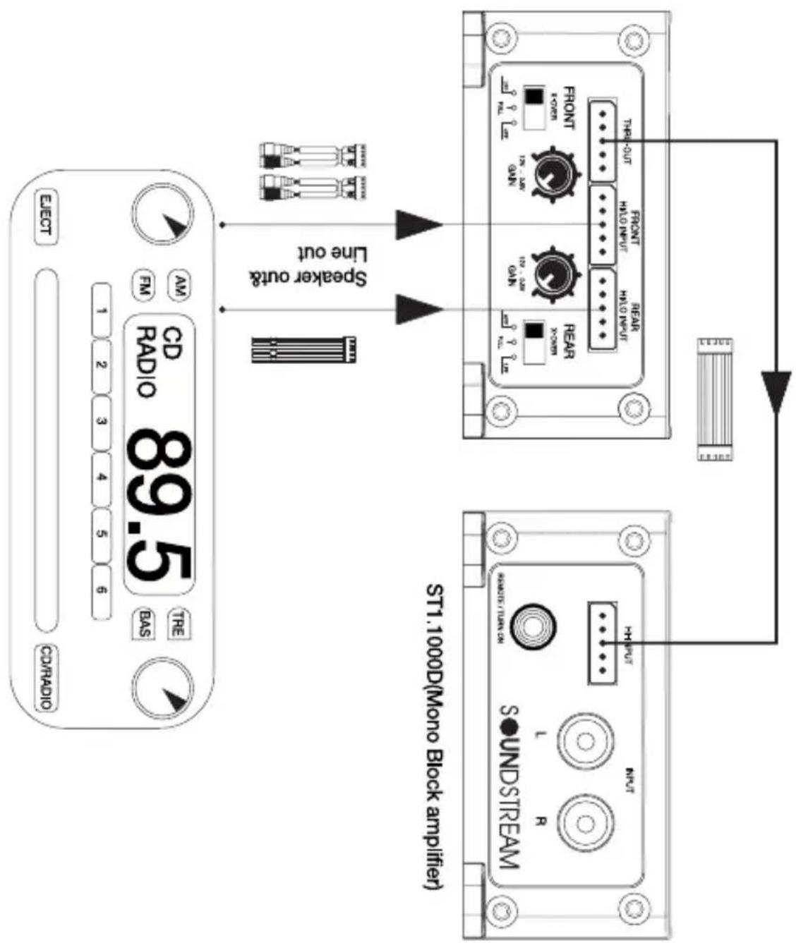
ST4.12001 4 channel Mode (4Ω\~8Ω)
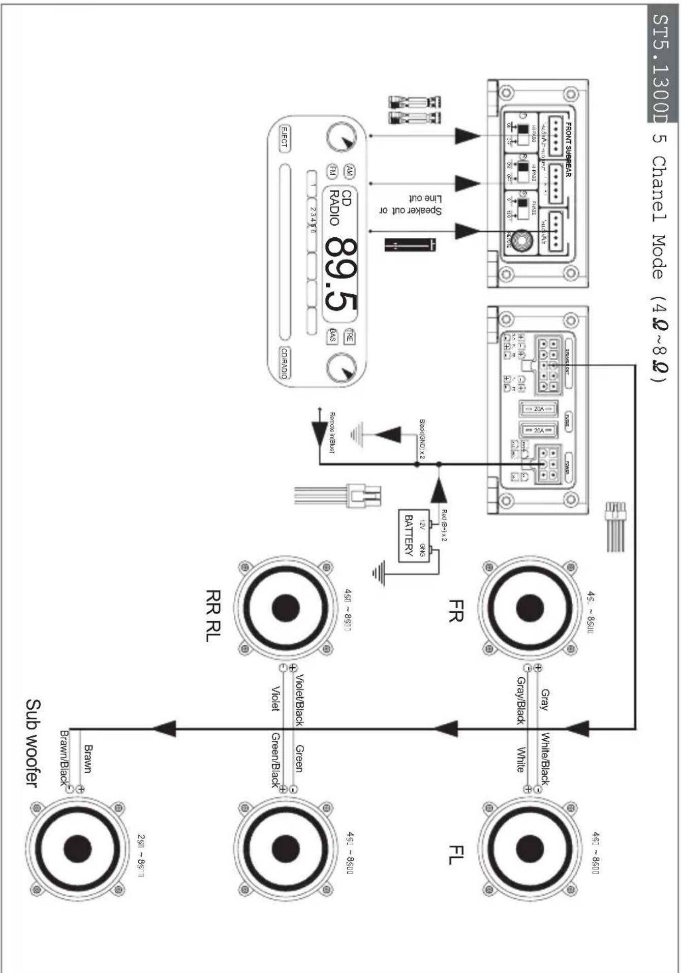
flowchart
graph TD
    A["Speaker out or Line out"] --> B["CD Radio 89.5"]
    B --> C["Front Substar"]
    C --> D["45 - 8500"]
    D --> E["Gray/Black White"]
    E --> F["White/Black +"]
    F --> G["Sub Wover"]
    G --> H["Brawn/Black +"]
    H --> I["250 - 8500"]
    I --> J["Green/Black +"]
    J --> K["450 - 8500"]
    K --> L["Violet/Black +"]
    L --> M["VR RL"]
    M --> N["Violet/Black +"]
    N --> O["Green/Black +"]
    O --> P["Brown/Black +"]
    P --> Q["Sub Wover"]
    style A fill:#f9f,stroke:#333
    style B fill:#ccf,stroke:#333
    style C fill:#cfc,stroke:#333
    style D fill:#fcc,stroke:#333
    style E fill:#cff,stroke:#333
    style F fill:#ffc,stroke:#333
    style G fill:#fcf,stroke:#333
    style H fill:#cff,stroke:#333
    style I fill:#ffc,stroke:#333
    style J fill:#cfc,stroke:#333
    style K fill:#fcc,stroke:#333
    style L fill:#ffc,stroke:#333
    style M fill:#cfc,stroke:#333
    style N fill:#fcc,stroke:#333
    style O fill:#ffc,stroke:#333
    style P fill:#cfc,stroke:#333
    style Q fill:#fcc,stroke:#333
Connect the ground by Black & Blue wire in If there comes engine noise, connect blue wire to the car radio chassis.
a normal.
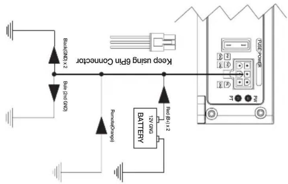
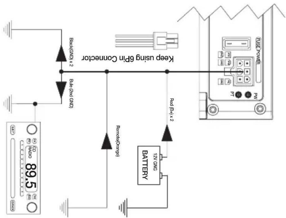
These amplifiers are designed to work within a 10 to 16.8 volt DC range. Before any wires are connected, the vehicles electrical system should be checked for correct voltage supply with the help of a voltmeter.
First, check the voltage at the battery with the ignition in the OFF position. The voltmeter should read not less than 12V. If your vehicles electrical system is not up to these specifications, we recommend having it checked by an auto electrician before any further installation. Once the vehicle is checked, make certain the correct cable size is used. We recommend using as large a gauge cable as possible, use the Power Cable Selection Chart to calculate the correct power wire size for your application.
Power
This amplifier should be wired directly to the vehicle battery using the appropriate size cable. Start at the vehicle battery and run the power cable through to the amplifier. Avoid running the power cable over engine components and near heater cores. The use of an online fuse o circuit breaker is a must ; this will prevent the risk of a potential fire caused by a short in your power cable. Connect the fuse holder or circuit beaker as close to the battery positive (+) terminal as possible ( no farther then 18" from the battery).This fuse or circuit breaker should be no greater then the sum of the fuses found on the chassis of your amplifier (also see specifications chart). You may now connect the cable to the battery, but remember to leave the fuse out or circuit breaker "off" until all other cable connections are made.
Ground
When grounding your amplifier, locate a metal area close to the amplifier that is good source of ground (preferably the floor pan). Once again, investigate the area you wish to use for electrical wires, vacuum lines, and brake or fuel lines. Use either a wire brush or sandpaper to eliminate unwanted paint for better contact of the ground. Secure the ground cable to the body using a bolt, star washer and nut. Spread silicon ove the wcrew and bare metal to prevent rust and possible water leaks.
Now it's time to connect the power and ground cable to the amplifier. Cut both cables to length. Strip off 1/2 - inch (12mm) of the insulation so that the bare wire will go all the way in the terminal block on the side panel of the amplifier, seating it firmly so no bare wire is exposed. Use a Philips (cross) type screwdriver to loosen the + BATT and the GND connections on the amplifier. Insert the ground first, and then the + 12V and please make sure that you place them into the correctly marked terminals.
Then tighten the screws down securely.
Remote
This terminal must be connected to a switched +12V source. Typically, remote turn-on leads are provided at the source unit that will turn on and off the amplifier in correspondence with the source.
If the source unit does not have a remote turn-on lead, then a switched +12V supply must be used, like the ACC, +12v.
TROUBLESHOOTING TIPS
| Problem | Solution |
| Power LED not ON | With a Volt Ohm Meter (VOM) check:• +12 Volt power terminal (should read +12 to +16VDC).• Remote turn-on terminal (should read +12 to+16VDC).• Ground Terminal. |
| Power LED is GREEN, no output | • Check RCA connections.• Test speaker outputs with known good speakerSubstitute known good Source Unit.• Check for signal on the RCA cable with VOM in AC position. |
| Protection LED is ON, no output and1. Amp is VERY HOT2. Amp shuts down ONLY when the vehicle is running3. Amp plays at very low volume | • Thermal protection is engaged. Check for proper impedance at speaker terminals. Also check for adequate air flow around the amplifier.Voltage protection engaged. Voltage to the amp is not within the 10-16.8 VDC operating range.Have the battery/charging system inspected.Short circuit protection is engaged. Check for speaker wires shorted to each other or the vehicle chassis. Speakers operating below the minimum impedance can cause this to occur. |
| Alternator noise (varies with RPM) | • Check for damaged RCA cable.• Check routing of RCA cable.• Check Source Unit for good ground.• Check amp gain setting, turn down if set too high. |
| Poor Bass Response | • Check speaker polarity, reverse the connection, of one speaker only. |
NOTE: If the RED protection LED. is activated with no speakers connected to the amplifier, and all the power connections are correct; this would indicate an internal problem with the amplifier. Contact Soundstream Technologies or your local dealer.
LIMITED 90-DAY CONSUMER WARRANTY
LIMITED TWO-YEAR CONSUMER WARRANTY WITH PURCHASE AND INSTALLATION BY A SOUNDSTREAM AUTHORIZED DEALER
Soundstream promises to the original purchaser, to repair or replace this product with a new or refurbished unit (at Soundstream's sole and absolute discretion) should it prove to be defective in workmanship or material under normal use, for a period of *two-years from the date of purchase from the Soundstream authorized dealer, PROVIDED the product was purchased and installed by a Soundstream authorized dealer. During this *two-year period, there will be no charge for product repair or replacement, PROVIDED the unit is returned to Soundstream, return shipping pre-paid, along with the required proof of installation, the bill of sale or other dated proof of purchase, and the consumer's contact information.
If the unit is installed by anyone other than a Soundstream authorized dealer, the warranty period will be 90-days from the date of purchase. This warranty is non-transferable and does not apply to any unit that has been modified or used in a manner contrary to its intended purpose, and does not cover damage to the unit caused by installation or removal of the unit. During this 90-day period, there will be no charge for the repair or replacement PROVIDED the unit is returned to Soundstream, return shipping prepaid, along with the bill of sale or other dated proof of purchase and the consumer's contact information.
This warranty is void if the product has been damaged by accident or unreasonable use, neglect, improper service or other causes not arising out of defects in materials or construction. This warranty does not cover the elimination of externally generated static or noise, or the correction of antenna problems or weak reception, damage to speakers, accessories, electrical systems, cosmetic damage or damage due to negligence, misuse, failure to follow operating instructions, accidental spills or customer applied cleaners, damage due to environmental causes such as floods, airborne fallout, chemicals, salt, hail, lightning or extreme temperatures, damage due to accidents, road hazards, fire, theft, loss or vandalism, damage due to improper connection to equipment of another manufacturer, modification of existing equipment, or Product which has been opened or tampered for any reason. Units which are found to be damaged by abuse resulting in thermally damaged voice coils are not covered by this warranty but may be replaced at the absolute and sole discretion of Soundstream. Unit must be returned to Soundstream, postage pre-paid, with bill of sale or other dated proof of purchase bearing the following information: consumer's name, telephone number, and address, authorized dealer's name and address, and product description. Please contact Soundstream warranty office at 800-724-1377 or repairs@soundstream.com to obtain a Return Authorization number prior to shipping the product.
Note: This warranty does not cover labor costs for the removal and reinstallation of the unit. IN ORDER FOR THE TWO-YEAR WARRANTY TO BE VALID, YOUR UNIT MUST BE SHIPPED WITH PROOF OF INSTALLATION BY A SOUNDSTREAM AUTHORIZED DEALER. ALL UNITS RECEIVED BY SOUNDSTREAM FOR WARRANTY REPAIR WITHOUT PROOF OF SOUNDSTREAM AUTHORIZED DEALER INSTALLATION AND PURCHASE WILL BE COVERED BY THE LIMITED 1 YEAR WARRANTY.
BY PURCHASING THIS PRODUCT, ALL WARRANTIES INCLUDING BUT NOT LIMITED TO EXPRESS WARRANTY, IMPLIED WARRANTY, WARRANTY OF MERCHANTABILITY, FITNESS FOR PARTICULAR PURPOSE, AND WARRANTY OF NON-INFRINGEMENT OF INTELLECTUAL PROPERTY ARE EXPRESSLY EXCLUDED TO THE MAXIMUM EXTENT ALLOWED BY LAW, AND SOUNDSTREAM NEITHER ASSUMES NOR AUTHORIZES ANY PERSON TO ASSUME FOR IT ANY LIABILITY IN CONNECTION WITH THE SALE OF THE PRODUCT. SOUNDSTREAM HAS ABSOLUTELY NO LIABILITY FOR ANY AND ALL ACTS OF THIRD PARTIES INCLUDING ITS AUTHORIZED DEALERS OR INSTALLERS. BY PURCHASING THIS PRODUCT, THE CONSUMER AGREES AND CONSENTS THAT ALL DISPUTES BETWEEN THE CONSUMER AND SOUNDSTREAM SHALL BE RESOLVED IN ACCORDANCE WITH CALIFORNIA LAWS IN LOS ANGELES COUNTY, CALIFORNIA.
Some states do not allow limitation on how long an implied warranty lasts. In such states, the limitation or exclusions of this Limited Warranty may not apply. Some states do not allow the exclusion or limitation of incidental or consequential damages. In such states, the exclusion or limitation of this Limited Warranty may not apply to you. This Limited Warranty gives you specific legal rights, and you may have other rights which vary from state to state.
- Congratulations on the new amplifier!
- Digital Micro Class D Premium Technology
- Caution, Read First
- TECHNICAL FEATURES
- ST1.1000D
- ST2.1000D
- ST3.1000D
- ST4.1200D
- ST5.1300D
- INSTALLATION PRECAUTIONS
- STALLATION PRECAUTIONS
- MOUNTING THE AMPLIFIER
- MOUNTING LOCATION
- LINE IN (RCA)
- High Level Input
- Thru-Out
- Remote Bass Boost Control
- SPEAKER Coneector.
- FUSE
- Power Input Connector
- Remote (Remote Input Connection)
- GND (Ground Input Connection)
- 10.Power Indicator
- Gain Adjustment Control
- Sub Sonic Filter
- Low Pass Filter
- Bass boost level control
- Protection Indicator
- High Pass ON/OFF Selector Switch
- High Pass Filter
- High Pass/Full/Low Pass Selector Switch
- Remote Subwoofer Level Control
- How to Installation
- Power
- Ground
- Remote
- TROUBLESHOOTING TIPS
Brand : Soundstream
Model : Stealth ST5.1300D
Category : Receiver