
PX1004UL - Video projector SHARP - Free user manual and instructions
Find the device manual for free PX1004UL SHARP in PDF.


| Product Type | Installation DLP Video Projector |
| Model Number | PX1004UL |
| Display Technology | Single-chip DLP 0.67" WUXGA |
| Native Resolution | 1920 x 1200 (WUXGA) Aspect ratio 16:10 |
| Brightness | 10000 lumens (typical) Adjustable 20-100% in 1% steps |
| Contrast Ratio | 2000:1 (typical) |
| Light Source | Laser diode module 360W max Life: long-life, no replacement needed |
| Lens | Optional (sold separately) Power zoom, focus, shift Lens calibration required after installation |
| Input Terminals | HDMI (x2), DisplayPort, BNC (5x), COMPUTER (D-Sub 15), HDBaseT (RJ-45), USB Type A (power only) |
| Output Terminal | HDMI OUT, 3D SYNC (Mini DIN 3-pin), PC CONTROL (D-Sub 9), REMOTE (stereo mini) |
| Network | Wired LAN (RJ-45) Supports Crestron RoomView, NaViSet, HTTP browser control |
| Keystone Correction | Digital Cornerstone (horizontal & vertical) Adjustable via menu |
| Lens Shift | Vertical & horizontal (powered) Adjustable from cabinet or remote |
| 3D Capability | Supports HDMI 3D format Requires optional 3D emitter and active shutter glasses |
| Power Supply | 110-240V AC, 50/60 Hz Power consumption: 11.6A-5.2A (max) |
| Standby Power | 0.30 W (NORMAL mode) 0.20 W (AC 110-130V) |
| Weight | 12.4 kg (27.3 lbs) excluding lens |
| Dimensions (W x H x D) | 484 x 185 x 379 mm (19.1 x 7.3 x 14.9 in) with lens |
| Noise Level | Less than 70 dB (A) (typical) |
| Operating Temperature | 0°C to 40°C (32°F to 104°F) Up to 3000 m altitude |
| Safety Class | Class 3R (IEC 60825-1 Ed.2) RG2 (IEC 62471-5) FCC Class A, ICES-003 |
| Included Accessories | Remote control (with batteries), power cords (3), dust cap, lens theft prevention screw, stacking holders, CD-ROM (manual), Quick Setup Guide |
Frequently Asked Questions - PX1004UL SHARP
User questions about PX1004UL SHARP
0 question about this device. Answer the ones you know or ask your own.
Ask a new question about this device
Download the instructions for your Video projector in PDF format for free! Find your manual PX1004UL - SHARP and take your electronic device back in hand. On this page are published all the documents necessary for the use of your device. PX1004UL by SHARP.
USER MANUAL PX1004UL SHARP
Please visit our web site for User's Manual in the latest version.
http://www.nec-display.com/dl/en/pj_manual/lineup.html
• Apple, Mac, Mac OS, and MacBook are trademarks of Apple Inc. registered in the U.S. and other countries.
- Microsoft, Windows, Windows Vista, Internet Explorer, .NET Framework and PowerPoint are either a registered trademark or trademark of Microsoft Corporation in the United States and/or other countries.
- MicroSaver is a registered trademark of Kensington Computer Products Group, a division of ACCO Brands.
- AccuBlend, NaViSet, and Virtual Remote are trademarks or registered trademarks of NEC Dispolay Solutions, Ltd. in Japan, in the United State and other countries.
- The terms HDMI and HDMI Hight-Definition Multimedia Interface, and the HDMI Logo are trademarks or registered trademarks of HDMI Licensing LLC in the United States and other countries.

HIGH-DEFINITION MULTIMEDIA INTERFACE
- DisplayPort and DisplayPort Compliance Logo are trademarks owned by the Video Electronics Standards Association.

- HDBaseT™ is a trademark of HDBaseT Alliance.

• DLP and BrilliantColor are trademarks of Texas Instruments.
- Trademark PJLink is a trademark applied for trademark rights in Japan, the United States of America and other countries and areas.
- Wi-Fi ^ , Wi-Fi Alliance ^ , and Wi-Fi Protected Access (WPA, WPA2 ^ ) are registered trademarks of the Wi-Fi Alliance.
- Blu-ray is a trademark of Blu-ray Disc Association
- CRESTRON and ROOMVIEW are registered trademarks of Crestron Electronics, Inc. in the United States and other countries.
- Ethernet is either a registered trademark or trademark of Fuji Xerox Co., Ltd.
- Extron and XTP are registered trademarks of RGB Systems, Inc. in the United States.
- Other product and company names mentioned in this user's manual may be the trademarks or registered trademarks of their respective holders.
• Virtual Remote Tool uses WinI2C/DDC library, © Nicomsoft Ltd.
• TOPPERS Software Licenses
The product includes software licensed under TOPPERS License.
For more information on each software, see "readme.pdf" inside the "about TOPPERS" folder on the supplied CD-ROM.
NOTES
(1) The contents of this user's manual may not be reprinted in part or whole without permission.
(2) The contents of this user's manual are subject to change without notice.
(3) Great care has been taken in the preparation of this user's manual; however, should you notice any questionable points, errors or omissions, please contact us.
(4) Notwithstanding article (3), NEC will not be responsible for any claims on loss of profit or other matters deemed to result from using the Projector.
Safety Cautions
Precautions
Please read this manual carefully before using your NEC projector and keep the manual handy for future reference.
CAUTION

To turn off main power, be sure to remove the plug from power outlet.
The power outlet socket should be installed as near to the equipment as possible, and should be easily accessible.
CAUTION

TO PREVENT SHOCK, DO NOT OPEN THE CABINET.
THERE ARE HIGH-VOLTAGE COMPONENTS INSIDE.
REFER SERVICING TO QUALIFIED SERVICE PERSONNEL.

This symbol warns the user that uninsulated voltage within the unit may be sufficient to cause electrical shock. Therefore, it is dangerous to make any kind of contact with any part inside of the unit.

This symbol alerts the user that important information concerning the operation and maintenance of this unit has been provided.
The information should be read carefully to avoid problems.
WARNING: TO PREVENT FIRE OR SHOCK, DO NOT EXPOSE THIS UNIT TO RAIN OR MOISTURE. DO NOT USE THIS UNIT'S PLUG WITH AN EXTENSION CORD OR IN AN OUTLET UNLESS ALL THE PRONGS CAN BE FULLY INSERTED.
DOC Compliance Notice (for Canada only)
This Class A digital apparatus complies with Canadian ICES-003.
Machine Noise Information Regulation - 3. GPSGV,
The highest sound pressure level is less than 70 dB (A) in accordance with EN ISO 7779.
Disposing of your used product
In the European Union
EU-wide legislation as implemented in each Member State requires that used electrical and electronic products carrying the mark (left) must be disposed of separately from normal household waste. This includes projectors and their electrical accessories. When you dispose of such products, please follow the guidance of your local authority and/or ask the shop where you purchased the product.
After collecting the used products, they are reused and recycled in a proper way. This effort will help us reduce the wastes as well as the negative impact to the human health and the environment at the minimum level.
The mark on the electrical and electronic products only applies to the current European Union Member States.
Outside the European Union
If you wish to dispose of used electrical and electronic products outside the European union, please contact your local authority and ask for the correct method of disposal.

For EU: The crossed-out wheeled bin implies that used batteries should not be put to the general household waste! There is a separate collection system for used batteries, to allow proper treatment and recycling in accordance with legislation.
According to the EU directive 2006/66/EC, the battery can't be disposed improperly. The battery shall be separated to collect by local service.
WARNING TO CALIFORNIA RESIDENTS:
Handling the cables supplied with this product will expose you to lead, a chemical known to the State of California to cause birth defects or other reproductive harm. WASH HANDS AFTER HANDLING.
RF Interference
WARNING
This is a Class A product. In a domestic environment this product may cause radio interference in which case the user may be required to take adequate measures.
CAUTION
- In order to reduce any interference with radio and television reception use a signal cable with ferrite core attached. Use of signal cables without a ferrite core attached may cause interference with radio and television reception.
- This equipment has been tested and found to comply with the limits for a Class A digital device, pursuant to Part 15 of the FCC Rules. These limits are designed to provide reasonable protection against harmful interference when the equipment is operated in a commercial environment. This equipment generates, uses, and can radiate radio frequency energy and, if not installed and used in accordance with the installation manual, may cause harmful interference to radio communications. Operation of this equipment in a residential area is likely to cause harmful interference in which case the user will be required to correct the interference at his own expense.
For UK only: In UK, a BS approved power cord with moulded plug has a Black (16 Amps) fuse installed for use with this equipment. If a power cord is not supplied with this equipment please contact your supplier.
Important Safeguards
These safety instructions are to ensure the long life of your projector and to prevent fire and shock. Please read them carefully and heed all warnings.
WARNING

- When the projector is damaged, cooling fluids may come out of internal part. Should this happen, immediately turn off the AC supply to the projector and contact your dealer. DO NOT touch and drink the cooling fluid. When the cooling fluids are swallowed or contacted with your eyes, please consult medical attention immediately. If you touch the cooling fluid with your hand, rinse your hands well under running water.

Installation
- Do not place the projector in the following conditions:
- on an unstable cart, stand, or table.
- near water, baths, or damp rooms.
- in direct sunlight, near heaters, or heat radiating appliances.
- in a dusty, smoky or steamy environment.
- on a sheet of paper or cloth, rugs or carpets.
- Do not install and store the projector in the below circumstances. Failure to do so may cause of malfunction.
- In powerful magnetic fields
- In corrosive gas environment
- Outdoors
- If you wish to have the projector installed on the ceiling:
- Do not attempt to install the projector yourself.
- The projector must be installed by qualified technicians in order to ensure proper operation and reduce the risk of bodily injury.
- In addition, the ceiling must be strong enough to support the projector and the installation must be in accordance with any local building codes.
- Please consult your dealer for more information.
WARNING
- Do not cover the lens with the lens cap or equivalent while the projector is on. Doing so can lead to melting of the cap due to the heat emitted from the light output.
- Do not place any objects, which are easily affected by heat, in front of the projector lens. Doing so could lead to the object melting from the heat that is emitted from the light output.

This projector can be installed any angle within vertical and horizontal 360^ range, however, life of optical parts will be shorten in the following installation state:
- When the projector is installed on which lens faces downward.
- When the intake vent on the projector side faces downward in the portrait installation. (→ page 155)
For portrait installation, install the projector with the intake vent at the bottom. Observe precautions for portrait installation.
* A customized stand is required to be attached to the projector. (→ page 156)

natural_image
Technical line drawing of a mechanical device with no visible text or symbols
Fire and Shock Precautions

- Ensure that there is sufficient ventilation and that vents are unobstructed to prevent the build-up of heat inside your projector. Allow enough space between your projector and a wall. (→ page xi)
-
Do not try to touch the exhaust vent on the rear side (when seen from the front) as it can become heated while the projector is turned on and immediately after the projector is turned off. Parts of the projector may become temporarily heated if the projector is turned off with the POWER button or if the AC power supply is disconnected during normal projector operation.
Use caution when picking up the projector. -
Prevent foreign objects such as paper clips and bits of paper from falling into your projector. Do not attempt to retrieve any objects that might fall into your projector. Do not insert any metal objects such as a wire or screwdriver into your projector. If something should fall into your projector, disconnect it immediately and have the object removed by a qualified service personnel.
- Do not place any objects on top of the projector.
- Do not touch the power plug during a thunderstorm. Doing so can cause electrical shock or fire.
- The projector is designed to operate on a power supply of 110-240V AC 50/60 Hz. Ensure that your power supply fits this requirement before attempting to use your projector.
- Do not look into the lens while the projector is on. Serious damage to your eyes could result.
- Do not look into the light source using optical instruments (such as magnifying glasses and mirrors). Visual impairment could result.
- When turning on the projector, ensure that nobody is facing towards the lens in the path of the light emitted from the laser. The following label, that is indicated at the lens-mounting-section on the projector cabinet, describes this projector is categorized in the risk group 2 of IEC62471-5: 2015. As with any bright light source, do not stare into the beam, RG2 IEC 62471-5: 2015.

RG2

natural_image
Diagram of a camera lens assembly with a blue pointer, showing no text or symbols- Keep any items (magnifying glass etc.) out of the light path of the projector. The light path being projected from the
lens is extensive, therefore any kind of abnormal objects that can redirect light coming out of the lens, can cause an unpredictable outcome such as a fire or injury to the eyes.
- Do not place any objects, which are easily affected by heat, in front of a projector exhaust vent.
Doing so could lead to the object melting or getting your hands burned from the heat that is emitted from the exhaust vent.
- Handle the power cord carefully. A damaged or frayed power cord can cause electric shock or fire.
- Do not use any power cord other than the one supplied with the projector.
- Do not bend or tug the power cord excessively.
- Do not place the power cord under the projector, or any heavy object.
- Do not cover the power cord with other soft materials such as rugs.
- Do not heat the power cord.
- Do not handle the power plug with wet hands.
- Turn off the projector, unplug the power cord and have the projector serviced by a qualified service personnel under the following conditions:
- When the power cord or plug is damaged or frayed.
- If liquid has been spilled into the projector, or if it has been exposed to rain or water.
- If the projector does not operate normally when you follow the instructions described in this user's manual.
- If the projector has been dropped or the cabinet has been damaged.
-
If the projector exhibits a distinct change in performance, indicating a need for service.
-
Disconnect the power cord and any other cables before carrying the projector.
- Turn off the projector and unplug the power cord before cleaning the cabinet.
- Turn off the projector and unplug the power cord if the projector is not to be used for an extended period of time.
- When using a LAN cable:
For safety, do not connect to the terminal for peripheral device wiring that might have excessive voltage.
- Do not use the malfunctioned projector. It may cause of not only electric shock or fire but also serious damage to your eye sight.
- Do not let children to operate the projector by themselves. If the projector is operated by children, adults need to attend and keep their eyes on children.
- If damage or malfunction of the projector is found, immediately stop to use it and consult your dealer for repair.
- Never disassemble, repair, and remodel by end users. If these are performed by end users, it may cause of serious problem on users' safety.
- Consult your dealer for disposing the projector. Never disassemble the projector before disposing it.
CAUTION
- Keep hands away from the lens mounting portion while performing a lens shift. Failure to do so could result in fingers being pinched by the moving lens.
- Do not use the tilt-foot for purposes other than originally intended. Misuses such as gripping the tilt-foot or hanging on the wall can cause damage to the projector.
- Select [HIGH] in Fan mode if you continue to use the projector for consecutive days. (From the menu, select [SETUP] → [INSTALLATION(1)] → [FAN MODE] → [HIGH].)
- Do not unplug the power cord from the wall outlet or projector when the projector is powered on. Doing so can cause damage to the AC IN terminal of the projector and (or) the prong plug of the power cord.
To turn off the AC power supply when the projector is powered on, use the projector's main power switch, a power strip equipped with a switch, or a breaker.
- When moving the projector, make sure you have at least two people. Attempting to move the projector alone could result in back pain or other injuries.
Caution on Handling the Optional Lens
When shipping the projector with the lens, remove the lens before shipping the projector. Always attach the dust cap to the lens whenever it is not mounted on the projector. The lens and the lens shift mechanism may encounter damage caused by improper handling during transportation.
Do not hold the lens part when carrying the projector.
Doing so could cause the focus ring to rotate, resulting in accidental dropping of the projector.
For mounting, replacing, and cleaning the lens, make sure to power off the projector and disconnect the power cord.
Failure to do so can result in eye injury, electric shock, or burn injuries.
Precautions when installing or replacing the lens unit sold separately (LENS CALIBRATION)
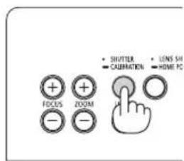
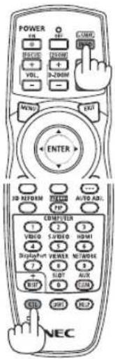
After installing or replacing the lens unit, press either the SHUTTER/CALIBRATION button on the main unit or the INFO/L-CALIB. button while pressing the CTL button on the remote control to carry out [LENS CALIBRATION]. (→ page 18, 120)
By carrying out [LENS CALIBRATION], the adjustment range of the zoom, focus, and shift of the [LENS MEMORY] is calibrated.
Contact your dealer to install and replace the lens unit.
Remote Control Precautions
- Handle the remote control carefully.
- If the remote control gets wet, wipe it dry immediately.
- Avoid excessive heat and humidity.
- Do not short, heat, or take apart batteries.
- Do not throw batteries into fire.
- If you will not be using the remote control for a long time, remove the batteries.
- Ensure that you have the batteries' polarity (+/−) aligned correctly.
- Do not use new and old batteries together, or use different types of batteries together.
- Dispose of used batteries according to your local regulations.
Light Module
- A light module containing multiple laser diodes is equipped in the product as the light source.
- These laser diodes are sealed in the light module. No maintenance or service is required for the performance of the light module.
- End user is not allowed to replace the light module.
- Contact qualified distributor for light module replacement and further information.
Laser Safety Caution
• This product is classified as RG2 of IEC62471-5 Edition 1.0 2015-06.
This product is classified as Class 3R of IEC 60825-1 Second edition 2007-03 and Class 1 of IEC60825-1 Third edition 2014-05.
Also complies with FDA performance standards 21 CFR 1040.10 and 1040.11 for laser products except for deviations pursuant to Laser Notice No.50, dated June 24, 2007.
Obey the laws and regulations of your country in relation to the installation and management of the device.
• Wave length 450–460 nm.
• Maximum power: 360 W
- The laser module is equipped in this product. Use of controls or adjustments of procedures other than those specified herein may result in hazardous radiation exposure.
CAUTION
- Use of controls or adjustments or performance of procedures other than those specified herein may result in hazardous radiation exposure.
CAUTION – CLASS 3R OF IEC 60825-1 SECOND EDITION LASER PRODUCT
LASER LIGHT – AVOID DIRECT EYE EXPOSURE
Applicable lens unit: NP16FL/NP17ZL/NP18ZL/NP19ZL/NP20ZL/NP21ZL/NP31ZL
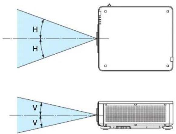
Horizontal angle H
| Lens Zoom | |
| Tele Wide | |
| NP16FL — 32.9 | |
| NP17ZL 15.5 21.7 | |
| NP18ZL 12.4 16.1 | |
| NP19ZL 7.7 12.7 | |
| NP20ZL 5.3 7 9 | |
| NP21ZL 3.4 5.4 | |
| NP31ZL 27.8 33.6 | |
Vertical angle V
| Lens Zoom | |
| Tele Wide | |
| NP16FL — 22.0 | |
| NP17ZL 9.8 14.0 | |
| NP18ZL 7.8 10.2 | |
| NP19ZL 4.8 8.0 | |
| NP20ZL 3.3 5.0 | |
| NP21ZL 2.1 3.4 | |
| NP31ZL 18.2 22.5 | |
Applicable lens unit: NP39ML
Horizontal angle H
| Lens Zoom | |
| Tele Wide | |
| NP39ML — 52.8 | |
Vertical angle V
| Lens Zoom | |||
| NP39ML — 9.68 21.52 | |||

- The caution and the explanatory labels of the LASER PRODUCT in CLASS 3R conforming to IEC60825-1 Second edition, and in Class 1 conforming to IEC60825-1 Third edition are stuck on the below indicated positions.
Label 1 Label 2


• Manufacturer's ID Label
(For PX1004UL-WH)
NEC MODEL No.NP-PX1004UL-WH
THIS DEVICE COMPLIES WITH PART 15 OF THE FCC RULES. OPERATION IS SUBJECT TO THE FOLLOWING TWO CONDITIONS: (1) THIS DEVICE MAY NOT CAUSE HARMFUL INTERFERENCE, AND (2) THIS DEVICE MUST ACCEPT ANY INTERFERENCE RECEIVED, INCLUDING INTERFERENCE THAT MAY CAUSE UNDESIGNED OPERATION.
CANICES-3(A)NMB-3(A)
Complies with FDA performance standards for laser products except for deviations pursuant to Laser Notice No.50, dated June 24, 2007. THIS CABINET IS CONSTRUCTED OF PLASTIC (PC).
Contact address for EMEA NEC Display Solutions Europe GmbH Landshuter Allee 12-14 80637 Munich, Germany
110-240V\~
50/60Hz 11.6A-5.2A
제품명: 프로젝터
NP-PX1004UL-WH ZU10002-16010 제조/국가 MSIP-REM-OVP-NP-PX1004UL
: TO REDUCE THE RISK OF FIRE OR ELECTRIC SHOCK, DO NOT EXPOSE THIS APPLIANCE TO RAIN OR MOISTURE.
POUR EVITER UN FEU OU UN RISQUE D' ELECTROCUTION NE PAS EXPOSER CET ENSEMBLE A LA PLUIE OU A L'NUMIDITE.
NEC Display Solutions, Ltd. 4-28, Mita 1-chome, Minato-ku, Tokyo, Japan MADE IN CHINA
XXXX XXXX

(For PX1004UL-BK)
NEC MODEL No.NP-PX1004UL-BK
110-240V\~
50/60Hz 11.6A-5.2A

THIS DEVICE COMPLIES WITH PART 15 OF THE FCC RULES, OPERATION IS SUBJECT TO THE FOLLOWING TWO CONDITIONS:(1) THIS DEVICE MAY NOT CAUSE HARMFUL INTERFERENCE, AND (2) THIS DEVICE MUST ACCEPT ANY INTERFERENCE RECEIVED, INCLUDING INTERFERENCE THAT MAY CAUSE UNDESIRED OPERATION.
CANIDES-3(A)NMB-3(A)
Complies with FDA performance standards for laser products except for deviations pursuant to Laser Notice No.50, dated June 24, 2007. THIS CABINET IS CONSTRUCTED OF PLASTIC (PC).
Contact address for EMEA NEC Display Solutions Europe GmbH Landshuter Allee 12-14 80637 Munich, Germany

제품명: 프로젝터
NP-FX1004UL-BK ZU10002-1501D 제조/국가 MSIP-REM-CVP-NP-FX1004UL
TO REDUCE THE RISK OF FIRE OR ELECTRIC SHOCK, DO NOT EXPOSE THIS APPLIANCE TO BAIN OR MOISTURE
AVERTISSEMENT
POUR EVITER UN FEU OU UN RISQUE D' ELECTROCUTION NE PAS EXPOSER CET ENSEMBLE A LA PLUIE OU A L'HUMIDITE.
NEC Display Solutions, Ltd. 4-28, Mita 1-chome, Minato-ku, Tokyo, Japan MADE IN CHINA

Position of the Manufacturer's ID Label

natural_image
Line drawing of a device rear panel with buttons, ports, and connectors (no text or symbols)About Copyright of original projected pictures:
Please note that using this projector for the purpose of commercial gain or the attraction of public attention in a venue such as a coffee shop or hotel and employing compression or expansion of the screen image with the following functions may raise concern about the infringement of copyrights which are protected by copyright law:
[ASPECT RATIO], [KEYSTONE], Magnifying feature and other similar features.
Turkish RoHS information relevant for Turkish market
Health precautions to users viewing 3D images
Before viewing, be sure to read health care precautions that may be found in the user's manual included with your 3D eyeglasses or your 3D compatible content such as Blu-ray Discs, video games, computer's video files and the like. To avoid any adverse symptoms, heed the following:
- Do not use 3D eyeglasses for viewing any material other than 3D images.
- Allow a distance of 2 m/7 feet or greater between the screen and a user. Viewing 3D images from too close a distance can strain your eyes.
- Avoid viewing 3D images for a prolonged period of time. Take a break of 15 minutes or longer after every hour of viewing.
- If you or any member of your family has a history of light-sensitive seizures, consult a doctor before viewing 3D images.
- While viewing 3D images, if you get sick such as nausea, dizziness, queasiness, headache, eyestrain, blurry vision, convulsions, and numbness, stop viewing them. If symptoms still persist, consult a doctor.
• View 3D images from the front of the screen. Viewing from an angle may cause fatigue or eyestrain.
Power management function
In order to keep power consumption low, the following power management functions (1) and (2) have been set when shipped from the factory. Please display the on-screen menu and change the settings (1) and (2) according to the aim of using the projector.
1. STANDBY MODE (Factory preset: NORMAL)
- When [NORMAL] is selected for [STANDBY MODE], the following terminals and functions will not work: HDMI OUT terminal, Ethernet/HDBaseT Port, USB Port, LAN functions, Mail Alert function
$$ (\rightarrow \text { page 136 }) $$
2. AUTO POWER OFF (Factory preset: 1 hour)
- When [1:00] is selected for [AUTO POWER OFF], you can enable the projector to automatically turn off in 1 hour if there is no signal received by any input or if no operation is performed.
$$ (\rightarrow \text { page 137 }) $$
Clearance for Installing the Projector
Allow ample clearance between the projector and its surroundings as shown below.
The high temperature exhaust coming out of the device may be sucked into the device again.
Avoid installing the projector in a place where air movement from the HVAC is directed at the projector.
Heated air from the HVAC can be taken in by the projector's intake vent. If this happens, the temperature inside the projector will rise too high causing the over-temperature protector to automatically turn off the projectors power.
- Concerning to the portrait projection, please refer "Portrait projection" on page 155.
Example 1 – If there are walls on both sides of the projector.
30 cm/11.8" or greater 30 cm/11.8" or greater

NOTE:
The drawing shows the proper clearance required for the left and right of the projector assuming sufficient clearance has been kept for the front, back and top of the projector.
Example 2 – If there is a wall behind the projector.

NOTE:
The drawing shows the proper clearance required for the back of the projector assuming sufficient clearance has been kept for the right, left and top of the projector.
Important Information......i
1. Introduction......1
① What's in the Box?....1
② Introduction to the Projector ....3
General 3
Light source · Brightness ....3
Installation....3
Videos....3
Network....4
Energy-saving....4
About this user's manual....5
③ Part Names of the Projector 6
Front/Top 6
Rear 7
Controls/Indicator Panel....8
Terminals Features....9
④ Part Names of the Remote Control ....10
Battery Installation 11
Remote Control Precautions....11
Operating Range for Wireless Remote Control 12
Using the Remote Control in Wired Operation....12
2. Projecting an Image (Basic Operation)....13
① Flow of Projecting an Image....13
② Connecting Your Computer/Connecting the Power Cord....14
Using the Supplied Power Cords....15
Using the Power Cord Stopper 16
③ Turning on the Projector....17
Performing Lens Calibration 18
Note on Startup screen (Menu Language Select screen)....19
④ Selecting a Source ....20
Selecting the computer or video source....20
⑤ Adjusting the Picture Size and Position....22
Adjusting the vertical position of a projected image (Lens shift) 23
Focus 26
Zoom....31
Adjusting the Tilt Foot 32
⑥ Optimizing Computer Signal Automatically 33
Adjusting the Image Using Auto Adjust....33
⑦ Turning off the Projector....34
⑧ After Use....35
3. Convenient Features....36
① Turn off the light of the projector (LENS SHUTTER)....36
② Turning off the Image (AV-MUTE)....36
③ Turning Off the On-Screen Menu (On-Screen Mute) 36
④ Shift the On-Screen Menu displaying position....37
⑤ Freezing a Picture ....37
6 Magnifying a Picture....38
⑦ Changing LIGHT MODE/Checking Energy-Saving Effect Using LIGHT MODE [LIGHT MODE]....39
Checking Energy-Saving Effect [CARBON METER] 41
⑧ Correcting Horizontal and Vertical Keystone Distortion [CORNERSTONE]....42
⑨ Preventing the Unauthorized Use of the Projector [SECURITY]......45
10 Projecting 3D videos....48
Procedure to watch 3D videos using this projector....48
When videos cannot be viewed in 3D....51
⑪ Controlling the Projector by Using an HTTP Browser ....52
⑫ Storing Changes for Lens Shift, Zoom, and Focus [LENS MEMORY]......60
To store your adjusted values in [REF. LENS MEMORY]: 61
To call up your adjusted values from [REF. LENS MEMORY]: 63
4. Multi-Screen Projection....66
① Things that can be done using multi-screen projection....66
Case 1. Using a single projector to project two types of videos [PIP/PICTURE BY PICTURE]....66
Case 2. Using four projectors (resolution: WUXGA) to project videos with a resolution of 2560 × 1600 pixels [TILING]....67
Things to note when installing projectors....69
② Displaying Two Pictures at the Same Time....70
Projecting two screens....71
Switching the main display with the sub-display and vice versa....72
Restrictions 73
③ Displaying a Picture Using [EDGE BLENDING]....74
Setting the overlap of projection screens....75
BLEND CURVE 77
Black Level Adjustment....78
5. Using On-Screen Menu....80
① Using the Menus....80
② Menu Elements....81
③ List of Menu Items 82
④ Menu Descriptions & Functions [INPUT]......88
HDMI....88
DisplayPort....88
BNC 88
BNC(CV) 88
BNC(Y/C) 88
COMPUTER 88
HDBaseT 88
SLOT....88
ENTRY LIST 88
TEST PATTERN....88
⑤ Menu Descriptions & Functions [ADJUST]......92
[PICTURE] 92
[IMAGE OPTIONS]......96
[VIDEO]....100
[3D SETTINGS]....102
Using the Lens Memory Function [LENS MEMORY]....103
⑥ Menu Descriptions & Functions [DISPLAY]....105
[PIP/PICTURE BY PICTURE]....105
[GEOMETRIC CORRECTION]....107
[EDGE BLENDING]....111
[MULTI SCREEN]....112
⑦ Menu Descriptions & Functions [SETUP]....114
[MENU(1)]....114
[MENU(2)]....115
[INSTALLATION(1)]....116
[INSTALLATION(2)]......119
[CONTROL]....121
[NETWORK SETTINGS]....129
[SOURCE OPTIONS]....134
[POWER OPTIONS]....136
Returning to Factory Default [RESET]....138
⑧ Menu Descriptions & Functions [INFO.] 139
[USAGE TIME]....139
[SOURCE(1)]....139
[SOURCE(2)]....140
[SOURCE(3)]....140
[SOURCE(4)]....140
[WIRED LAN]....141
[VERSION(1)]....141
[OTHERS]....141
[HDBaseT]....142
6. Connecting to Other Equipment....143
① Mounting a lens (sold separately)....143
Mounting the lens....143
Removing the lens 144
② Making Connections....145
Analog RGB signal connection....145
Digital RGB signal connection ....146
Connecting an External Monitor....149
Connecting Your Blu-ray Player or Other AV Equipment 150
Connecting Component Input 151
Connecting HDMI Input....152
Connecting to a Wired LAN 153
Connecting to an HDBaseT transmission device (sold commercially)....154
Portrait projection (vertical orientation)....155
Stacking projectors .... 157
7. Maintenance .... 160
① Cleaning the Lens....160
② Cleaning the Cabinet....160
8. Appendix......161
① Throw distance and screen size....161
Lens types and throw distance 161
Tables of screen sizes and dimensions....163
Lens shifting range....164
② Mounting the Optional Board (sold separately)....165
③ Compatible Input Signal List....167
4 Specifications 170
Power Cord....173
⑤ Cabinet Dimensions ....174
6 Pin assignments and signal names of main terminals....175
⑦ Changing the Background Logo (Virtual Remote Tool)....177
⑧ Troubleshooting....178
Indicator Messages....178
Common Problems & Solutions....180
If there is no picture, or the picture is not displayed correctly....182
⑨ PC Control Codes and Cable Connection....183
10 Troubleshooting Check List....184
1. Introduction
① What's in the Box?
Make sure your box contains everything listed. If any pieces are missing, contact your dealer. Please save the original box and packing materials if you ever need to ship your projector.
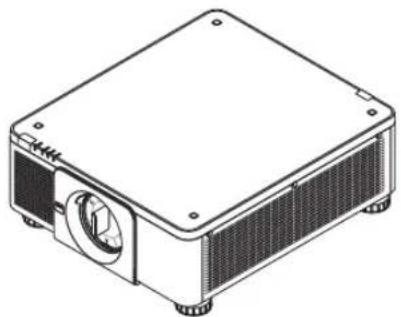
Projector
natural_image
Isometric line drawing of a rectangular electronic device with a central circular component and mounting holes (no text or symbols)Dust cap for lens
* The projector is shipped without a lens. For the types of lens and throw distances, see page 172.
natural_image
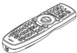
Line drawing of a remote control with keypad and scroll (no text or symbols)Remote control (7N901041)
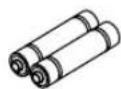
AA alkaline batteries (x2)

Lens theft prevention screw (79TM1071)
This screw makes it difficult to remove the lens mounted on the projector. (→ page 144)
Power cord × 3
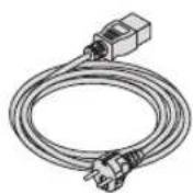


(79TM1021) (79TQ1001 for AC 120 V) (79TQ1011 for AC 200 V)
For Europe/Asia/South America For North America
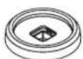


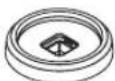
4 Stacking holders (79TM1101)
When stacking projectors (double stacking), the tilt foot of the upper projector will be placed onto these stacking holders. (→ page 158)

natural_image
Two overlapping gray rectangular sheets with no text or symbols• Important Infomation (7N8N7461)
• Quick Setup Guide (7N8N7471)
• Security Sticker
(Use this sticker when security password is set on.)

NEC Projector CD-ROM
User's manual (PDF)
(7N952521)
For North America only
Limited warranty
For customers in Europe:
You will find our current valid Guarantee Policy on our Web Site: www.nec-display-solutions.com
Attaching/Removing the Dust Cap
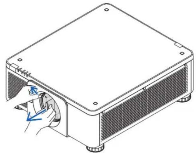
To remove the dust cap from the projector, tongue at the top left outward and pull the knob at the center of the cap.
Toattach the dust cap to the projector, locate the catch on the lower end of the dust cap and place it into the opening of the projector with the point of a triangle mark (▽) facing downward (① in the figure below), and then push the upper end of the dust cap against the projector to place the catches into the slot while clutching the handle (② in the figure below).
natural_image
Technical line drawing of a mechanical device with a hand inserting a component into the housing (no text or symbols)
natural_image
Technical line drawing of a rectangular electronic device with labeled components (1, 2), showing internal structure and mounting points (no text or symbols beyond labels)② Introduction to the Projector
This section introduces you to your new projector and describes the features and controls.
General
- Single-chip DLP projector with high resolution and high brightness
Realized to project the image in the resolution 1920 × 1200 pixels (WUXGA), the aspect ratio in 16:10, and the brightness in 10000 lumens.
• Superior dust-proof structure
Adapted the cycle cooling system for cooling down the optical parts. By this system, air in the light source is cooled down and circulated. As the result, the optical parts are not exposed to the open air and enable to keep brightness without contamination by dust.
* Can not prevent contamination by dust completely.
Light source · Brightness
• A long-life laser diode is equipped in the light module
The product can be operated at low cost because the laser light source can be used for a long time without requiring replacement or maintenance.
• Brightness can be adjusted within a wide range
Unlike with ordinary light sources, the brightness can be adjusted from 20 to 100% in 1% increments.
• [CONSTANT BRIGHTNESS] mode
Brightness normally decreases with use, but by selecting [CONSTANT BRIGHTNESS] mode, sensors inside the projector detect and automatically adjust the output, thereby maintaining constant brightness throughout the life of the light module.
However, if brightness output is set at the maximum, brightness will decrease with use.
Installation
- Wide range of optional lenses selectable according to the place of installation
This projector supports 8 types of optional lenses, providing a selection of lenses adapted to a variety of places of installation and projection methods.
In addition, the lenses can be mounted and removed in one touch.
Note that no lens is mounted upon shipment from the factory. Please purchase optional lenses separately.
- This projector can be installed any angle within vertical and horizontal 360° range, however, life of optical parts will be shorten in the following installation state:
- When the projector is installed on which lens faces downward.
- When the intake vent on the projector side faces downward in the portrait installation. (See page 155)
• Double stackable for high light output projection
By stacking 2 projectors, increased brightness on a large screen is possible.
• Power lens control for quick and easy adjustment
By using buttons on the projector or the remote control, zoom, focus, and position (lens shift) can be adjusted.
Videos
- Wide range of input/output terminals (HDMI, DisplayPort, BNC, HDBaseT, etc.) and built-in monaural speaker
The projector is equipped with a variety of input/output terminals: HDMI, DisplayPort, BNC (5-core), computer (analog), HDBaseT, etc.
The projector's HDMI input/output terminals and DisplayPort input terminal support HDCP.
HDBaseT, promoted and advanced by the HDBaseT Alliance, is a consumer electronic (CE) and commercial connectivity technology.
- Slot for optional board
This projector has a slot for optional boards (sold separately).
• Simultaneous display of 2 images (PIP/PICTURE BY PICTURE)
Two images can be projected simultaneously with a single projector.
There are two types of layouts for the two images: "picture-in-picture" (PIP) in which a sub-picture is displayed on the main picture, and "picture-by-picture" (PICTURE BY PICTURE) in which the main and sub pictures are displayed next to each other.
• Multi-screen projection using multiple projectors
This projector is equipped with multiple HDMI input & output terminals that can connect multiple projectors in a daisy chain. By dividing and projecting high resolution image on each projector, high quality image can be realized.
Furthermore, the boundaries of the screens are smoothed using an edge blending function.
• Supports HDMI 3D format
This projector can be used to watch videos in 3D using commercially-available 3D emitters that support Xpand 3D and active shutter-type 3D eyewear.
Network
- Convenient utility software (User Supportware)
This projector supports our utility software (NaViSet Administrator 2, Virtual Remote Tool, etc.).
NaViSet Administrator 2 helps you control the projector by a computer via wired LAN connection.
Virtual Remote Tool helps you perform operations by a virtual remote control such as projector's power on or off and signal selection via wired LAN connection. Moreover, it has function to send an image to the projector and register it as the logo data.
Please visit our web site for downloading each software.
URL: http://www.nec-display.com/dl/en/index.html
- CRESTRON ROOMVIEW compatible
This projector supports CRESTRON ROOMVIEW, allowing multiple devices connected to the network to be managed from a computer or controller.
Energy-saving
• Energy-saving design with a standby power consumption of 0.30 watts or under
When the on-screen menu's standby mode is set to "NORMAL", the power consumption in the standby mode is 0.30 watts or under.
0.20 watts with power voltage AC110V-130V and 0.30 watts with power voltage AC200V-240V.
- “LIGHT MODE” for low power consumption and “Carbon Meter” display
The projector is equipped with an “LIGHT MODE” for reducing power consumption during use. Furthermore, the power-saving effect when the LIGHT MODE is set is converted into the amount of reductions of CO_2 emissions and this is indicated on the confirmation message displayed when the power is turned off and at “Information” on the on-screen menu (CARBON METER).
About this user's manual
The fastest way to get started is to take your time and do everything right the first time. Take a few minutes now to review the user's manual. This may save you time later on. At the beginning of each section of the manual you'll find an overview. If the section doesn't apply, you can skip it.
③ Part Names of the Projector
Front/Top
The lens is sold separately. The description below is for when the NP18ZL lens is mounted.

Rear

* This security slot supports the MicroSaver® Security System.
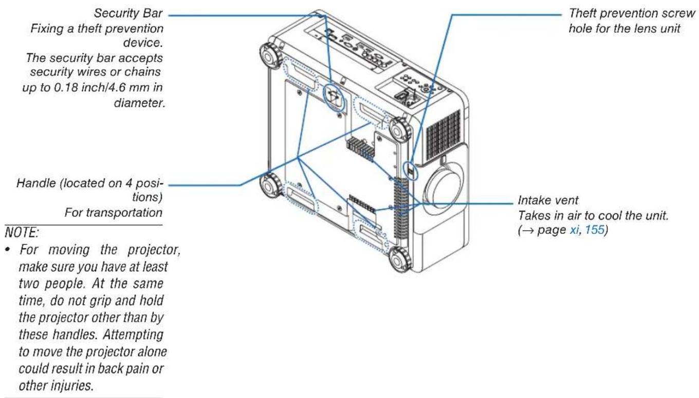
Controls/Indicator Panel

- (POWER) Button
(→ page 18, 34)
- POWER Indicator
(→ page 17, 18, 34, 178)
- STATUS Indicator
( → page 178)
- LIGHT Indicator
(→ page 39, 179)
- TEMP. Indicator
( → page 179)
- SOURCE Button
( → page 20)
- AUTO ADJ. Button
( → page 33)
- 3D REFORM Button
( → page 42)
- MENU Button
( → page 80)
- ▲▼◀▶ Buttons
( → page 80)
- ENTER Button
( → page 80)
- EXIT Button
( → page 80)
- SHUTTER/CALIBRATION Button
( → page 36)
- LIGHT Button
( → page 39)
- LENS SHIFT/HOME POSITION Button
(→ page 23, 60, 164)
- FOCUS +/- Button
( → page 26)
- ZOOM +/- Button
( → page 31)
Terminals Features

- COMPUTER IN (Mini D-Sub 15 Pin)
(→ page 14, 145, 151, 175)
(→ page 146, 148, 152, 175)
- BNC IN [R/Cr/CV, G/Y/Y, B/Cb/C, H, V] Terminals (BNC × 5)
(→ page 145, 150)
- BNC (Y/C) Input Terminal (BNC × 2)
( → page 150)
- BNC (CV) Input Terminal (BNC × 1)
( → page 150)
- USB Port (Type A)
( → page 176)
(For future expansion. This port allows for power supply.)
- HDMI OUT Terminal (Type A)
( → page 149)
- Ethernet/HDBaseT Port (RJ-45)
(→ page 153, 154, 176)
- 3D SYNC Terminal (Mini DIN 3 Pin)
( → page 48)
- PC CONTROL Port (D-Sub 9 Pin)
(→ page 176, 183)
Use this port to connect a PC or control system. This enables you to control the projector using serial communication protocol. If you are writing your own program, typical PC control codes are on page 183.
12. REMOTE Terminal (Stereo Mini)
Use this jack for wired remote control of the projector using a commercially available remote cable with ∅3.5 stereo mini-plug (without resistance).
Connect the projector and the supplied remote control using a commercially available wired remote control cable.
(page 12)
NOTE:
- When a remote control cable is connected to the REMOTE terminal, infrared remote control operations cannot be performed.
- Power cannot be supplied from the REMOTE terminal to the remote control.
- When [HDBaseT] is selected in the [REMOTE SENSOR] and the projector is connected to a commercially-available transmission device that supports HDBaseT, remote control operations in infra-red cannot be carried out if transmission of remote control signals has been set up in the transmission device. However, remote control using infrared rays can be carried out when the power supply of the transmission device is switched off.
13. SLOT
( → page 165)
14. Service terminal
For service only
④ Part Names of the Remote Control

- Infrared Transmitter ( → page 12)
- Remote Jack
Connect a commercially available remote cable here for wired operation. (→ page 12)
- POWER ON Button ( → page 18)
- POWER OFF Button ( → page 34)
- INFO/L-CALIB. Button
Display the [SOURCE(1)] screen of the on-screen menu. ( page 18, 139)
- VOL./FOCUS +/- Buttons ( → page 26)
- D-ZOOM/ZOOM +/- Buttons ( → page 38)
- TEST Button ( → page 88)
- ECO/L-SHIFT Button (→ page 25, 39)
- MENU Button ( → page 80)
- EXIT Button ( → page 80)
- ENTER Button ( → page 80)
- ▲▼◀▶ Button ( → page 80)
- ON-SCREEN Button ( → page 36)
- SHUTTER Button ( → page 36)
- AV-MUTE Button ( → page 36)
- PICTURE Button (→ page 92, 94)
- SOURCE Button ( → page 20)
- 3D REFORM Button ( → page 42)
-
PIP/FREEZE Button (→ page 37, 71)
-
AUTO ADJ. Button ( → page 33)
22, 23. COMPUTER 1/2 Button ( → page 20) - COMPUTER 3 Button
(This button is not work on this projector.)
- VIDEO Button ( → page 20)
- S-VIDEO Button ( → page 20)
- HDMI Button ( → page 20)
- DisplayPort Button ( → page 20)
- VIEWER Button
(The VIEWER button will not work on this series of projectors.)
- NETWORK Button ( → page 20)
- SLOT Button (→ page 20, 165)
- ID SET Button ( → page 127)
- Numeric (0 to 9/CLEAR) Buttons ( page 127)
(The AUX button will not work on this series of projectors.)
- CTL Button
This button is used in conjunction with other buttons, similar to a CTRL key on a computer.
- LIGHT Button
This button is used to turn on the backlight for the remote control buttons.
The backlight will turn off if no button operation is made for 10 seconds.
- HELP Button ( → page 13
Battery Installation
-
Press the catch and remove the battery cover.
-
Install new ones (AA). Ensure that you have the batteries' polarity (+/-) aligned correctly.
-
Slip the cover back over the batteries until it snaps into place.
NOTE: Do not mix different types of batteries or new and old batteries.


natural_image
Technical line drawing of a car interior showing internal components and a blue arrow indicating a specific location (no text or symbols present)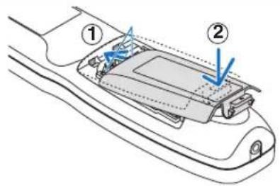
Remote Control Precautions
- Handle the remote control carefully.
• If the remote control gets wet, wipe it dry immediately. - Avoid excessive heat and humidity.
- Do not short, heat, or take apart batteries.
- Do not throw batteries into fire.
- If you will not be using the remote control for a long time, remove the batteries.
- Ensure that you have the batteries' polarity (+/-) aligned correctly.
- Do not use new and old batteries together, or use different types of batteries together.
- Dispose of used batteries according to your local regulations.
Operating Range for Wireless Remote Control
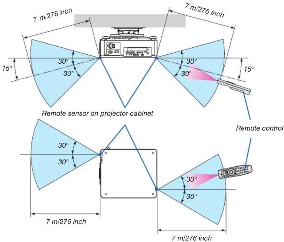
- The infrared signal operates by line-of-sight up to a distance of above meters and within a 60-degree angle of the remote sensor on the projector cabinet.
- The projector will not respond if there are objects between the remote control and the sensor, or if strong light falls on the sensor. Weak batteries will also prevent the remote control from properly operating the projector.
Using the Remote Control in Wired Operation
Connect one end of the remote cable to the REMOTE terminal and the other end to the remote jack on the remote control.

NOTE:
- When a remote cable is inserted into the REMOTE terminal, the remote control does not work for infrared wireless communication.
- Power will not be supplied to the remote control by the projector via the REMOTE jack. Battery is needed when the remote control is used in wired operation.
2. Projecting an Image (Basic Operation)
This section describes how to turn on the projector and to project a picture onto the screen.
① Flow of Projecting an Image
Step 1
- Connecting your computer / Connecting the power cord (→ page 14)

Step 2
• Turning on the projector ( page 17)

Step 3
• Selecting a source ( page 20)

Step 4
- Adjusting the picture size and position (→ page 22)
- Correcting keystone distortion [CORNERSTONE] (→ page 42)

Step 5
- Adjusting a picture
- Optimizing a computer signal automatically ( page 33)

Step 6
• Making a presentation

Step 7
• Turning off the projector ( page 34)

Step 8
• After use ( page 35)
② Connecting Your Computer/Connecting the Power Cord
1. Connect your computer to the projector.
This section will show you a basic connection to a computer. For information about other connections, see “(2) Making Connections” on page 145.
Connect the display output terminal (mini D-sub 15 pin) on the computer to the COMPUTER IN terminal on the projector with a commercially-available computer cable (with ferrite core) and then turn the knobs of the terminals to secure them.
2. Connect the supplied power cord to the projector.

WARNING
MAKE SURE TO TAKE THE GROUND CONNECTION FOR THE DEVICE. TO PREVENT FIRE OR SHOCK, DO NOT EXPOSE THIS UNIT TO RAIN OR MOISTURE.
DO NOT USE THIS UNIT'S PLUG WITH AN EXTENSION CORD OR IN AN OUTLET UNLESS ALL PRONGS CAN BE FULLY INSERTED.
Important Information:
- When plugging in or unplugging the supplied power cord, make sure that the main power switch is pushed to the off [O] position. Failure to do so may cause damage to the projector.
- Do not use a three-phase power supply. Doing so may cause of malfunction.
First connect the supplied power cord's three-pin plug to the AC IN terminal of the projector, and then connect the other plug of the supplied power cord in the wall outlet.


CAUTION:
Parts of the projector may become temporarily heated if the projector is turned off with the POWER button or if the AC power supply is disconnected during normal projector operation.
Use caution when picking up the projector.
Using the Supplied Power Cords
Select the power cord suitable for your country or region.
For Europe/Asia/South America For North America

natural_image
Illustration of a multi-pin electrical outlet with wires (no text or symbols)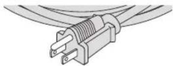
natural_image
Illustration of a U-shaped electrical plug with wires (no text or symbols)
natural_image
Illustration of a power plug with three leads, connected to coiled cables (no text or symbols)(120 V) (200 V)
(→ page 173)
Using the Power Cord Stopper
To prevent the power cord from accidentally removing from the AC IN of the projector, attach the power cord stopper to clamp the power cord.

CAUTION
- To prevent the power cord from coming loose, make sure that all the prongs of the power cord are fully inserted into the AC IN terminal of the projector before using the power cord stopper to fix the power cord. A loose contact of the power cord may cause a fire or electric shock.
Attaching the power cord stopper
- Raise up the power cord stopper and lay it over the power cord.
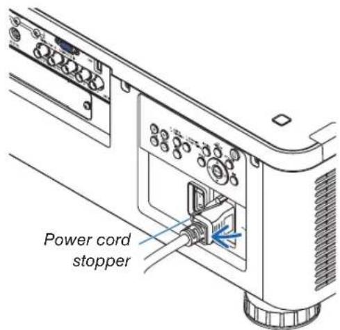
- For releasing the stopper, raise up the stopper and lay it down to the opposite side.

natural_image
Line drawing of a projector module with cable and connector (no text or symbols)③ Turning on the Projector
NOTE:
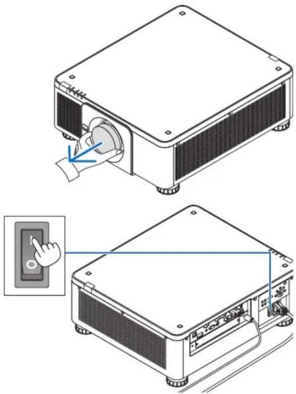
- The projector has two power switches: A main power switch and a POWER button (POWER ON and OFF on the remote control)
- Turning on the projector:
- Press the main power switch to the ON position (I).
The projector will go into standby mode.
- Press the POWER button.
The projector will become ready to use.
- Turning off the projector:
- Press the POWER button.
The confirmation message will be displayed.
- Press the POWER button again.
The projector will go into standby mode.
- Press the main power switch to the OFF position (O).
The projector will be turned off.
-
Remove the lens cap from the lens unit.
-
Press the main power switch to the ON position (I).
The POWER indicator lights up red.*
* This indicates that the STANDBY mode is in [NORMAL] setting.
(→ page 136, 178)

WARNING
The projector produces a strong light. When turning on the power, make sure no one within projection range is looking at the lens.
NOTE:
- The [STANDBY MODE] setting will be disabled and the projector will go into the sleep mode when the network service is utilized or the projector receives HDBaseT signal. In the sleep mode, the fans in the projector rotate for the purpose of interior parts protection. Please refer to page 136 about the sleep mode.
natural_image
Technical illustration of a projector unit with a hand operating its screen, showing internal components and wiring (no text or symbols present)3. Press the POWER) button on the projector cabinet or the POWER ON button on the remote control.
The POWER indicator goes from a steady red light to a flashing blue light, and the picture is projected on the screen.
TIP:
- When the message "PROJECTOR IS LOCKED! ENTER YOUR PASSWORD." is displayed, it means that the [SECURITY] feature is turned on. (→ page 45)
After you turn on your projector, ensure that the computer or video source is turned on.
NOTE: The blue screen ([BLUE] background) is displayed when no signal is being input (by factory default menu settings).

flowchart
graph TD
    A["SOURCE"] --> B["UNITS"]
    C["3D REFORM"] --> B
    D["AUTO AP"] --> B
    E["MENU"] --> B
    F["EXIT"] --> B

Standby Blinking Power On


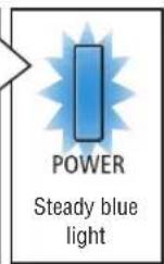
(→ page 178)
Performing Lens Calibration
After installation or replacement of the lens, be sure to perform [LENS CALIBRATION] by pressing and holding the SHUTTER/CALIBRATION button on the projector cabinet for at least two seconds or by holding the CTL button and pressing the INFO/L-CALIB. button on the remote control. Perform [LENS CALIBRATION] also when trouble is found on the lens shift motion. Calibration corrects the adjustable zoom, shift, and focus range. If calibration is not performed, you may not be able to get the best focus and zoom even if you adjust the focus and zoom for the lens. While performing Lens Calibration, the STATUS indicator flashes in green twice per cycle.
- The following lenses need calibration: NP16FL, NP17ZL, NP18ZL, NP19ZL, NP20ZL, NP21ZL, NP31ZL
Note on Startup screen (Menu Language Select screen)
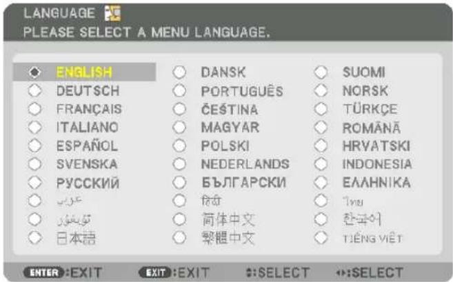
When you first turn on the projector, you will get the Startup menu. This menu gives you the opportunity to select one of the 30 menu languages.
To select a menu language, follow these steps:
1. Use the ▲, ▼, ◀ or ▶ button to select one of the 30 languages from the menu.

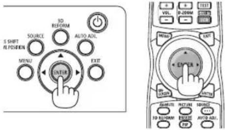
2. Press the ENTER button to execute the selection.
After this has been done, you can proceed to the menu operation.
If you want, you can select the menu language later.
(→ [LANGUAGE] on page 84 and 114)
NOTE:
- If one of the following things happens, the projector will not turn on.
- If the internal temperature of the projector is too high, the projector detects abnormal high temperature. In this condition the projector will not turn on to protect the internal system. If this happens, wait for the projector's internal components to cool down.
- If the STATUS indicator lights orange with the power button pressed, it means that the [CONTROL PANEL LOCK] is turned on. Cancel the lock by turning it off. (→ page 126)
- While the POWER indicator is blinking blue in short cycles, the power cannot be turned off by using the power button. (While the POWER indicator is blinking blue in long cycles, the OFF TIMER is functioned and the power can be turned off.)
4 Selecting a Source
Selecting the computer or video source
NOTE: Turn on the computer or video source equipment connected to the projector.
Detecting the Signal Automatically
Press the SOURCE button for 1 second or longer. The projector will search for the available input source and display it. The input source will change as follows:
HDMI → DisplayPort → BNC → BNC(CV) → BNC(Y/C) → COMUPTER → HDBaseT → SLOT → ...

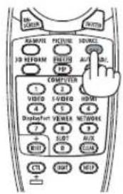
- Press it briefly to display the [INPUT] screen.

Press the ▼/▲ buttons to match the target input terminal and then press the ENTER button to switch the input. To delete the menu display in the [INPUT] screen, press the MENU or EXIT button.
TIP: If no input signal is present, the input will be skipped.
Using the Remote Control
Press any one of the HDMI, DisplayPort, COMPUTER 2, VIDEO, S-VIDEO, COMPUTER 1, NETWORK, or SLOT buttons.
• COMPUTER 2 button selects the BNC IN terminal.
• VIDEO button selects the BNC (CV) input terminal (Composite Video).
- S-VIDEO button selects the BNC (Y/C) input terminal (S-Video).

Selecting Default Source
You can set a source as the default source so that it will be displayed each time the projector is turned on.
1. Press the MENU button.
The menu will be displayed.
2. Press the ▶ button to select [SETUP].
3. Press the ▶ button to select [SOURCE OPTIONS].
4. Press the ▼ button four times to select [DEFAULT INPUT SELECT] and press the ENTER button.
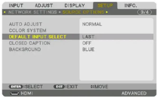
The [DEFAULT INPUT SELECT] screen will be displayed.
(→ page 134)
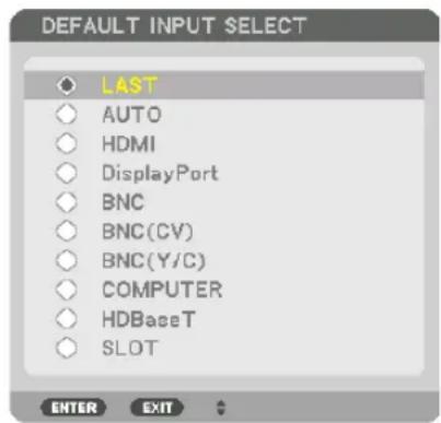
5. Select a source as the default source, and press the ENTER button.
6. Press the EXIT button three times to close the menu.
7. Restart the projector.
The source you selected in step 5 will be projected.
NOTE: Even when [AUTO] is turned on, the [HDBaseT] will not be automatically selected. To set your network as the default source, select [HDBaseT].
TIP:
- When the projector is in Standby mode, applying a computer signal from a computer connected to the COMPUTER IN input will power on the projector and simultaneously project the computer's image.
([AUTO POWER ON SELECT] → page 137)
- On the Windows 7 keyboard, a combination of the Windows and P keys allows you to set up external display easily and quickly.
⑤ Adjusting the Picture Size and Position
Use the lens shift dial, the adjustable tilt foot, the zoom ring and the focus ring to adjust the picture size and position. In this chapter drawings and cables are omitted for clarity.
Adjusting the projected image's vertical and horizontal position[Lens shift](→ page 23) | Adjusting the focus[Focus](→ page 26)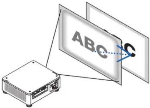 |
Finely adjusting the size of an image[Zoom](→ page 31) | Adjusting the projected image's height and horizontal tilt [Tilt foot]*1(→ page 32) |
NOTE ^*1 : Adjust the projected image's height using the tilt foot when you want to project the image at a position higher than the lens shift adjustment range.
TIP:
- Built-in test patterns can be conveniently used for adjusting the picture size and position. (→ page 88) A press of the TEST button will display the test pattern. The ◀ or ▶ button can select one test pattern. To close the test pattern, change the source to another.
Adjusting the vertical position of a projected image (Lens shift)

CAUTION
- Perform the adjustment from behind or from the side of the projector. Performing adjustment from the front could expose your eyes to strong light which could injure them.
- Keep hands away from the lens mounting portion while performing a lens shift. Failure to do so could result in fingers being pinched by the moving lens.
NOTE:
- The lens shift function is not available on the projector with either NP16FL or NP39ML lens installed.
For using NP16FL, set back the lens to the home position.
For using NP39ML, select [SETUP] → [INSTALLATION(2)] → [LENS POSITION] → [TYPE] on the onscreen menu, the lens will be moved to the appropriate position automatically.
- Shifting the lens to the maximum in oblique angle will cause the edges of the image to become dark or will cause dark shadows.
Adjusting with buttons on the cabinet
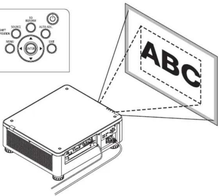
1. Press the LENS SHIFT/HOME POSITION button.
The [LENS SHIFT] screen will be displayed.

2. Press the ▼▲◀ or ▶ button.
Use the ▼▲◀▶ buttons to move the projected image.

- Returning the lens shift position to the home position
Press and hold the LENS SHIFT/HOME POSITION button for 2 seconds to return the lens shift position to the home position (nearly center position)
Adjusting with the remote control
1. Hold the CTL button and press the ECO/L-SHIFT button.
The [LENS SHIFT] screen will be displayed.

2. Press the ▼▲◀ or ▶ button.
Use the ▼▲◀▶ buttons to move the projected image.


NOTE:
Lens Calibration
If the power of the projector is wrongly shut down during the motion of lens shift, it may shift the home position of the lens and may cause of malfunction. The STATUS indicator flashed in Orange to inform this kind of trouble occurrence. (→ page 178) In this case, perform lens calibration.
Lens calibration procedures
-
Power on the projector.
-
Press the (SHUTTER/CALIBRATION) button on the control panel over 2 seconds or keep pressing the CTL button and press the INFO/L-CALIB. button on the remote control.
Calibration is performed.
TIP:
- The diagram below shows the lens shift adjustment range (projection mode: desktop front). To raise the projection position higher than this, adjust by the tilt foot. (→ page 32)

Description of symbols: V indicates vertical (height of the projected image), H indicates horizontal (width of the projected image).
Focus
Applicable lens unit: NP16FL/NP17ZL/NP18ZL/NP19ZL/NP20ZL/NP21ZL
1. Press the FOCUS +/- button until you can obtain the best focus.
(The FOCUS adjustment bar will be displayed on.)

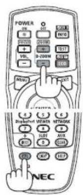
- On the remote control, while pressing on the CTL button, press on VOL/FOCUS (+) or (−) button.
- ◀ or ▶ buttons on the cabinet or the remote control are also available to adjust FOCUS while the FOCUS adjustment bar is displayed on.

TIP:
To obtain the best focus, perform the following (for permanent installation)
Preparation: Warm up the projector for one hour.
- Use the FOCUS +/- buttons to make sure you obtain the best focus. If you do not, move the projector back and forth.
- Select the [TEST PATTERN] from the menu and display the test pattern. (→ page 88)
- You can also use the TEST button on the remote control to display the test pattern.
- Keep pressing the FOCUS -button until the grid of the text pattern is made invisible.
- The FOCUS adjustment bar displaying position can be shifted or be turned off temporarily. (→ page 36, 37)
- Keep pressing the FOCUS + button until you obtain the best focus.
If you adjust beyond the best focal point, go back to step 3 and repeat the procedures.
Applicable lens unit: NP31ZL
1. Focus on the projected image around the optical axis. (Powered focus)
Press the FOCUS +/− button until you can obtain the best focus.
(The FOCUS adjustment bar will be displayed on.)

The drawing below shows an example when the projected image is shifted upward. In this case the optical axis is at the bottom edge of the projected image.
Adjusting with buttons on the cabinet
Press the FOCUS +/- BUTTON on the control panel
Adjusting with the remote control
Press the VOL/FOCUS button holding the CTL button
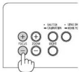

- ◀ or ▶ buttons on the cabinet or the remote control are also available to adjust FOCUS while the FOCUS adjustment bar is displayed on.

* When the lens is at the center position, the optical axis is at the center of the image. In this case, adjust the focus at the center of the projected image.

natural_image
Grid pattern with uniform black squares on white background (no text or symbols)2. Adjust the focus at the edges of the projected image. (Manual focus)
Turn the edge focus ring clockwise or counterclockwise.

This completes adjusting the projected image's overall focus.
NOTE:
The NP31ZL supports the Lens Memory function, which allows you to store adjusted value for Lens Shift, Zoom, and Focus. If you accidentally move the Edge focus ring (drawing shown below) after having stored adjusted values, the adjusted values stored in the Lens Memory will not be correctly applied.
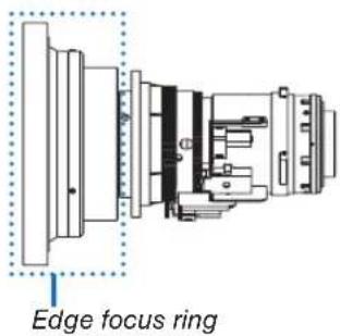
After having removed the lens from the projector and mounted it back, call up the adjusted values stored in the Lens Memory and then follow Step 2 in the procedure above to adjust the focus at the edges of the projected image again.
TIP: To obtain the best focus, perform the following (for permanent installation)
Preparation: Warm up the projector for one hour.
-
Press the FOCUS +/- buttons to check the adjustable focus range. For checking it by the remote control, press and hold the CTL button and press VOL./FOCUS +/- button. If the projector in use is not within the adjustable focus range, move the projector back and forth.
-
Select the [TEST PATTERN] from the menu and display the test pattern. (→ page 88)
- For displaying the test pattern by the remote control, press TEST button.
- Keep pressing the FOCUS - button until the grid of the text pattern becomes invisible.
- The FOCUS adjustment bar displaying position can be shifted or be turned off temporarily. (→ page 36, 37)
- Keep pressing the FOCUS + button until you obtain the best focus.
For obtaining the best focus by the remote control, press the VOL./FOCUS + button while holding to press the CTL button. If you adjust beyond the best focal point, go back to step 3 and repeat the procedures.
- Turn the edge focus ring clockwise or counterclockwise to adjust the focus at the edges of the projected image.
Applicable lens unit: NP39ML
1. Focus on the projected image around the optical axis. (Powered focus)
The optical axis is at the bottom of the image.
Press the FOCUS +/- button until you can obtain the best FOCUS around the optical axis. (The FOCUS adjustment bar will be displayed on.)

In another way, press the VOL/FOCUS +/- button while holding to press the CTL button on the remote control.
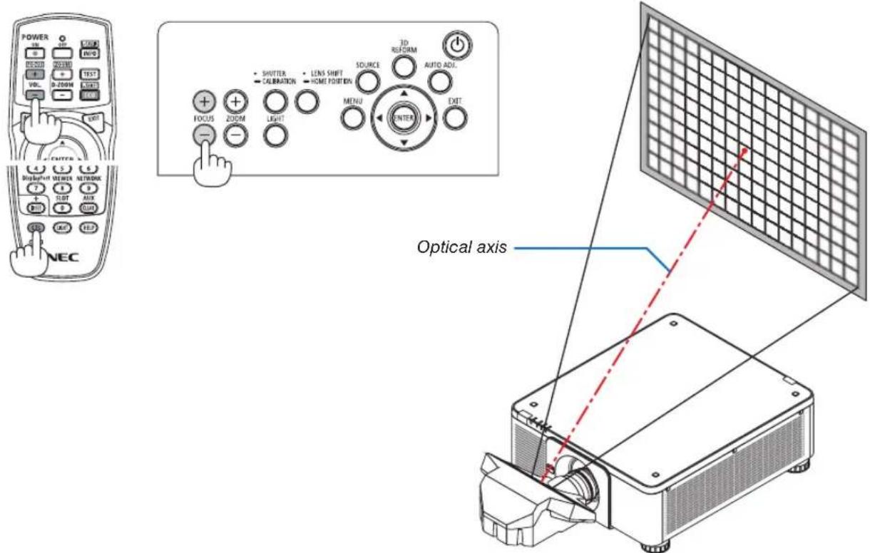
- ◀ or ▶ buttons on the cabinet or the remote control are also available to adjust FOCUS while the FOCUS adjustment bar is displayed on.
2. Adjust the focus at the edges of the projected image.
Press either the ZOOM +/- button on the control panel or the D-ZOOM/ZOOM +/- button while holding to press the CTL button on the remote control until you can obtain the best focus at the edges of the projected image. (The ZOOM adjustment bar will be displayed on.)

Focus around the optical axis set at step 1 is remained unchanged.


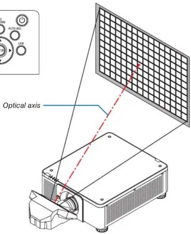
3. Repeat steps 1 and 2 until the optimal focus can be obtained on whole image.
TIP:
To obtain the best focus, perform the following (for permanent installation)
Preparation: Warm up the projector for one hour.
-
Use the FOCUS +/- buttons to make sure you obtain the best focus. If you do not, move the projector back and forth.
-
Select the [TEST PATTERN] from the menu and display the test pattern. (→ page 88)
- You can also use the TEST button on the remote control to display the test pattern.
- Keep pressing the FOCUS - button until the grid of the text pattern is made invisible.
- The FOCUS adjustment bar displaying position can be shifted or be turned off temporarily. (→ page 36, 37)
- Keep pressing the FOCUS + button until you obtain the best focus.
If you adjust beyond the best focal point, go back to step 3 and repeat the procedures.
- Press the ZOOM +/- button for adjusting the edges of the projected image.
Press the D-ZOOM/ZOOM +/- button holding to press the CTL button for adjusting it by the remote control.
Repeat steps 1 to 5 until the optimal focus can be obtained on whole image.
Zoom
Applicable lens units: NP17ZL/NP18ZL/NP19ZL/NP20ZL/NP21ZL/NP31ZL
- Press the ZOOM +/- button.
The ZOOM adjustment bar will be displayed on.

- On the remote control, while pressing on the CTL button, press the D-ZOOM/ZOOM (+) or (−) button. The zoom is adjusted.
- ◀ or ▶ buttons on the cabinet or the remote control are available to adjust ZOOM while the ZOOM adjustment bar is displayed on.

Adjusting the Tilt Foot
- The position to project image may be adjusted by positioned at four corners of the cabinet bottom.
The tilt foot height can be adjusted by its turn.
"To adjust the height of the projected image"
The height of the projected image is adjusted by turning either front or rear tilt foot.
"If the projected image is tilted"
If the projected image is tilted, turn either left or right tilt foot to adjust the image so that it is level.
- If the projected image is distorted, see "3-8 Correcting Horizontal and Vertical Keystone Distortion [CORNERSTONE]" (→ page 42) and "[GEOMETRIC CORRECTION]" (→ page 107).
• The tilt foot can be lengthened by a maximum of 48 mm. - The tilt foot can be used to tilt the projector by a maximum of 6^ .


NOTE:
- Do not lengthen the tilt foot any more than 50 mm/1.9". Doing so will make the tilt feet's mount section unstable and could cause the tilt feet to come off the projector.
- Pay attention to lengthen or shorten two tilt foot at front at the same time. Same for the rear foot, otherwise, the weight of the projector is loaded on one side and it may cause of damage to it.
- Do not use the tilt foot for any purpose other than adjusting the projector's projection angle.
Handling the tilt foot improperly, such as carrying the projector by grasping the tilt foot or hooking it onto a wall using the tilt foot, could damage the projector. - Please check level of the lens unit When the lens unit NP39ML is installed on since the lens unit may slightly incline in left or right.
Tilt foot
(there is one more in the rear)
⑥ Optimizing Computer Signal Automatically
Adjusting the Image Using Auto Adjust
When an image from HDMI IN, DisplayPort IN, BNC IN terminal (analog RGB), COMPUTER IN, or HDBaseT is being projected, and the edge is cut off or the image quality is poor, this button can be used to automatically optimize the projection image on the screen.
Press the AUTO ADJ. button to optimize a computer image automatically.


[Poor picture] [Adjusted picture]
NOTE:
Some signals may take time to display or may not be displayed correctly.
- If the Auto Adjust operation cannot optimize the computer signal, try to adjust [HORIZONTAL], [VERTICAL], [CLOCK], and [PHASE] manually. (→ page 96, 97)
• If you can not obtain an optimized picture, refer page 182.
⑦ Turning off the Projector
- Press the ⓊPOWER) button on the projector cabinet or the POWER OFF button on the remote control.
The [POWER OFF / ARE YOU SURE ? / CARBON SAVINGS- SESSION 0.000[g-CO2]] message will appear.
![POWER OFF ARE YOU SURE ? CARBON SAVINGS-SESSION 0.000[g-CO2] YES NO](/content/2026/05/957502/images/e21a767b82cee931bdfb8c4469fb439f6481f8e136c08a3760237f564ebcab26.jpg)

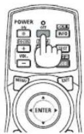
- Press one among the ENTER, the ⓄPOWER), and the POWER OFF button.
When the projector is in STANDBY MODE, the POWER indicator lights up red. (When [STANDBY MODE] is in [NORMAL] setting)
- If you do not want to turn off, select [NO] by ◀/▶ button and press ENTER.
- Make sure the projector is in STANDBY MODE, then turn off the main power switch (○ OFF)
The POWER indicator will go off and the main power will turn off.
- While the POWER indicator is blinking blue in short cycles, the power cannot be turned off.


CAUTION:
Parts of the projector may temporarily overheat if the projector is turned off with the main power switch or the AC power supply is disconnected while the projector is in operation or the cooling fan is running. Handle with care.
NOTE:
- Do not unplug the power cord from the projector or from the power outlet while an image is being projected. Doing so could deteriorate the projector's AC IN terminal or the power plug's contact. To turn off the AC power supply when the projector is powered on, use the projector's main power switch, a power strip equipped with a switch, or a breaker.
- Do not turn off the main power switch or disconnect the AC power supply within 10 seconds of making adjustments or setting changes and closing the menu. Doing so can cause loss of adjustments and settings.
⑧ After Use
Preparation: Make sure that the projector is turned off.
- Unplug the power cord.
- Disconnect any other cables.
- Mount the lens cap on the lens.
- Before moving the projector, screw in the tilt foot if they have been lengthened.
3. Convenient Features
① Turn off the light of the projector (LENS SHUTTER)
Press the SHUTTER/CALIBRATION button.
The light source will turn off temporarily.
Press again to allow the screen to become illuminated again.
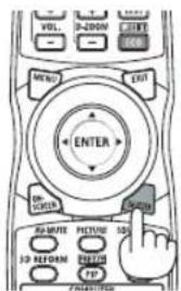
- Another way to shut the light source off is to press the SHUTTER button on the remote control.
- You can set the projection light to gradually fade in or out.

NOTE:
- [LENS SHUTTER] is functioned by quick press. If press and hold the SHUTTER/CALIBRATION button over 2 seconds, it will start the LENS CALIBRATION.
② Turning off the Image (AV-MUTE)
Press the AV-MUTE button to turn off the image for a short period of time. Press again to restore the image.

TIP:
• The video will disappear but not the menu display.
③ Turning Off the On-Screen Menu (On-Screen Mute)
A press of the ON-SCREEN button on the remote control will hide the on-screen menu, the source display and other messages. Press again to restore them.

TIP:
- To confirm that the on-screen mute is turned on, press the MENU button. If the on-screen menu is not displayed even though you press the MENU button, it means the on-screen mute is turned on.
- The on-screen mute is maintained even when the projector is turned off,
- Holding down the MENU button on the projector cabinet for at least 10 seconds will turn off the on-screen mute.
④ Shift the On-Screen Menu displaying position
1. Press the MENU button.
The On-Screen Menu will be displayed on.
2. Move the cursor by the ▶ button to the [SETUP] and then press the ENTER button.
The cursor will move to the [MENU1].
3. Move the cursor by the ▶ button to the [MENU2].

4. Move the cursor by the ▼ button to the [MENU POSITION] and then press the ENTER.
The On-Screen Menu will goes into the MENU POSITION setup screen.

5. Move the cursor either TO [HORIZONTAL POSITION] or [VERTICAL POSITION] by pressing ▼ or ▲ button and then press ◀/▶ button to shift the On-Screen Menu.
For finishing the setting on the On-Screen Menu, press the MENU button on the remote control.
TIP:
- Once the projector is powered off, the On-Screen Menu displaying position will be reset to the default factory setting position.
- This function does not influence to the display position of input terminal information and message.
⑤ Freezing a Picture
Hold the CTL button and press the PIP/FREEZE button to freeze a picture. Press again to resume motion.
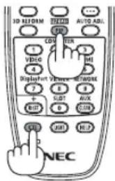
NOTE: The image is frozen but the original video is still playing ahead.
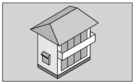
6 Magnifying a Picture
You can magnify the picture up to four times.
NOTE:
- Depending on an input signal, the maximum magnification may be less than four times, or the function may be restricted.
To do so:
1. Press the D-ZOOM (+) button to magnify the picture.
natural_image
Isometric illustration of a two-story house with a gabled roof and window (no text or symbols)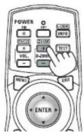

natural_image
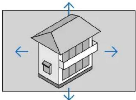
Isometric view of a building facade with a sloped roof and adjacent window (no text or symbols)2. Press the ▲▼◀▶ button.
The area of the magnified image will be moved
natural_image
Isometric diagram of a two-story house with directional arrows indicating orientation (no text or symbols)
3. Press the D-ZOOM (−) button.
Each time the D-ZOOM (−) button is pressed, the image is demagnified.

NOTE:
- The image will be magnified or demagnified at the center of the screen.
- Displaying the menu will cancel the current magnification.
⑦ Changing LIGHT MODE/Checking Energy-Saving Effect Using LIGHT MODE [LIGHT MODE]
When either [ECO1] or [ECO2] in [LIGHT MODE] is selected, motion noise of the projector is cut down by lowering brightness of its light source. By saving energy consumption, the CO_2 emission from this projector can be reduced.
| LIGHT MODE | Icon at the bottom of the menu | Description |
| NORMAL | 100% brightnessThe screen will be brightly lit. | |
ECO1 Brightness will be at about 80%. ![SHARP PX1004UL - ⑦ Changing LIGHT MODE/Checking Energy-Saving Effect Using LIGHT MODE [LIGHT MODE] - 1](/content/2026/05/957502/images/fb66f15f717c3404e26dceffadacf71374e773bae69aa39258fe1fafd1d8ae00.jpg) | The cooling fan will also slow down accordingly.Lower power consumption | |
| ECO2 | ![SHARP PX1004UL - ⑦ Changing LIGHT MODE/Checking Energy-Saving Effect Using LIGHT MODE [LIGHT MODE] - 2](/content/2026/05/957502/images/e9036ba37795c5d4a8f342e67ac558f5b546c3f5b05ed169189eedc5e211d6fe.jpg) | Brightness will be at about 50%.The cooling fan will also slow down accordingly.Lower power consumption considerably |
To turn on the [LIGHT MODE], do the following:
1. Press LIGHT button on the cabinet.
- In another way, press ECO/L-SHIFT button on the remote control.


The [LIGHT MODE] screen will be displayed.
2. Press the ENTER button.
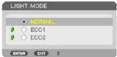
The [LIGHT MODE] selection screen will be displayed.
3. Use the ▼▲ buttons to make a selection, and press the ENTER button.
The display will return to the [LIGHT MODE] screen and the selected option will be applied.
Press the MENU button to return to the original screen.
NOTE:
- The [LIGHT MODE] can be changed by using the menu.
Select [SETUP] → [INSTALLATION(1)] → [LIGHT MODE] → [LIGHT MODE].
- The light module hours used can be checked in [USAGE TIME] on the menu. Select [INFO.] [USAGE TIME].
- After a lapse of 1 minute from when the projector displays a blue, black or logo screen, [LIGHT MODE] will automatically switch to [ECO].
- This projector equips the sensor to detect atmospheric pressure and temperature and the projector controls the power based on the detected values. When the projector is used in high altitude and high temperature, the light source brightness becomes lower regardless of the setting for LIGHT MODE. This is called “Forced ECO MODE”. Please refer the below table for the conditions and output power in Forced ECO MODE.
| Altitudes Atmospheric temperature | ||||
| 5–25°C(41–77°F) | 26–30°C(78–86°F) | 31–35°C(87–95°F) | 36–40°C(96–104°F) | |
| 1600–3000 m(5500–10000 ft) | 100% 90% 80% 70% | |||
| 1200–1600 m(4000–5500 ft) | 100% 90% 80% | |||
| 0–1200 m(0–4000 ft) | 100% 80% | |||
- When the projector is in the Forced LIGHT MODE, the picture brightness decreases slightly and the TEMP. indicator lights orange. At the same time the Thermometer symbol [1] is displayed at the bottom of the screen.
When the projector comes back to normal temperature, the Forced ECO MODE is cancelled and the [LIGHT MODE] returns to [NORMAL] mode. When the atmospheric pressure sensor detects height over 1200 m, the HIGH symbol [☐] will be displayed at the bottom of the screen.
Checking Energy-Saving Effect [CARBON METER]
This feature will show energy-saving effect in terms of CQemission reduction (kg) when the projector's [LIGHT MODE] is set to either [ECO1] or [ECO2]. This feature is called as [CARBON METER].
There are two messages: [TOTAL CARBON SAVINGS] and [CARBON SAVINGS-SESSION]. The [TOTAL CARBON SAVINGS] message shows the total amount of CQ emission reduction from the time of shipment up to now. You can check the information on [USAGE TIME] from [INFO.] of the menu. (→ page 139)
![INPUT ADJUST DISPLAY SETUP INFO. USAGE TIME SOURCE(1) SOURCE(2) 1/3 LIGHT HOURS USED 00000 [H] TOTAL CARBON SAVINGS 0.000[kg-CO2] EXIT:EXIT MOVE MOVE HDMI ADVANCED](/content/2026/05/957502/images/b5ae078da61cae3b9064925f3f3032332bbc43d3c99a15743d55196f29459e9d.jpg)
The [CARBON SAVINGS-SESSION] message shows the amount of CO _2 emission reduction between the time of changing to LIGHT MODE immediately after the time of power-on and the time of power-off. The [CARBON SAVINGS-SESSION] message will be displayed in the [POWER OFF/ ARE YOU SURE ?] message at the time of power-off.
![POWER OFF ARE YOU SURE ? CARBON SAVINGS-SESSION 0.000[g-CO2] YES NO](/content/2026/05/957502/images/b2f1ab3d82760294560f12b76ce742fc9a0b95c69c7442d6c2c9b1ae05e7b7ab.jpg)
TIP:
- The formula shown below is used to calculate the amount of CO_2 emission reduction. Amount of CO_2 emission reduction = (Power consumption in [NORMAL] LIGHT MODE – Power consumption in current setting) × CO_2 conversion factor. * When an energy-saving LIGHT MODE is selected, or the Lens Shutter is used, there will be a further reduction in CO_2 emission.
* Calculation for amount of CO_2 emission reduction is based on an OECD publication “CO _2 Emissions from Fuel Combustion, 2008 Edition”. - The [TOTAL CARBON SAVINGS] is calculated based on savings recorded in 15 minutes intervals.
- This formula will not apply to the power consumption which is not affected by whether [LIGHT MODE] is turned on or off.
⑧ Correcting Horizontal and Vertical Keystone Distortion [CORNERSTONE]
Use the [CORNERSTONE] feature to correct keystone (trapezoidal) distortion to make the top or bottom and the left or right side of the screen longer or shorter so that the projected image is rectangular.
1. Project an image so that the screen is smaller than the area of the raster.
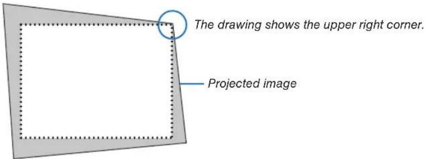
2. Pick up any one of the corners and align the corner of the image with a corner of the screen.
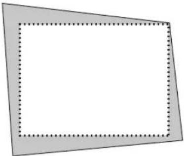
natural_image
Simple geometric diagram with a rectangle and dotted inner lines, no text or symbols present.3. Press the 3D REFORM button.
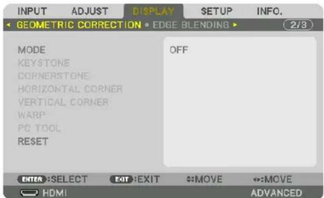
Display the [GEOMETRIC CORRECTION] screen of the on-screen menu.
4. Move the cursor onto [MODE] by ▼ button and press the ENTER.
The mode selection screen will displayed on.

- Press the ▼ button to align with the [CORNERSTONE] and then press the ENTER button.

The drawing shows the upper left icon (▼) is selected.
The screen will switch to the [CORNERSTONE] screen.
- Use the ▲▼◀▶ button to select one icon (▲) which points in the direction you wish to move the projected image frame.
- Press the ENTER button.
- Use the ▲▼◀▶ button to move the projected image frame as shown on the example.

- Press the ENTER button.
- Use the ▲▼◀▶ button to select another icon which points in the direction.
![SHARP PX1004UL - Move the cursor onto [MODE] by ▼ button and press the ENTER. - 4](/content/2026/05/957502/images/a4cf4fa9c238dcdd2d671ed6e2366b71fd326932a4d2cda7343e33a4c4cc59ff.jpg)
natural_image
Simple diagram of a device with a control panel and directional arrows, enclosed in a dotted rectangular frame (no text or symbols)
- Repeat steps from 7 to 10 to complete the cornerstone adjustment.
- On the [CORNERSTONE] screen, select [EXIT] or press the EXIT button on the remote control.

The confirmation screen is displayed.
13. Press the ◀ or ▶ button to highlight the [OK] and press the ENTER button.
This completes the [CORNERSTONE] correction.
- Returning to the [CORNERSTONE] screen, select [CANCEL] and press the ENTER button.
NOTE:
- Even if the installation angle is changed when the projector is turned on again, the correction values in the previous time has been maintained.
-
Carry out either one of the following actions to clear the adjustment value of [CORNERSTONE].
-
In Step 12, select [RESET] and then press the ENTER button.
-
In the state [CORNERSTONE] has been selected for [MODE] in the [GEOMETRIC CORRECTION]:
-
Press the 3D REFORM button for 2 or more seconds.
- Run [GEOMETRIC CORRECTION] [RESET] in the on-screen menu.
• Using CORNERSTONE correction can cause the image to be slightly blurred because the correction is made electronically.
⑨ Preventing the Unauthorized Use of the Projector [SECURITY]
A keyword can be set for your projector using the Menu to avoid operation by an unauthorized user. When a keyword is set, turning on the projector will display the Keyword input screen. Unless the correct keyword is entered, the projector cannot project an image.
- The [SECURITY] setting cannot be cancelled by using the [RESET] of the menu.
To enable the Security function:
1. Press the MENU button.
The menu will be displayed.
- Press the ▶ button twice to select [SETUP] and press the ▼ button or the ENTER button to select [MENU(1)].

- Press the ▶ button to select [CONTROL].
- Press the ▼ button three times to select [SECURITY] and press the ENTER button.
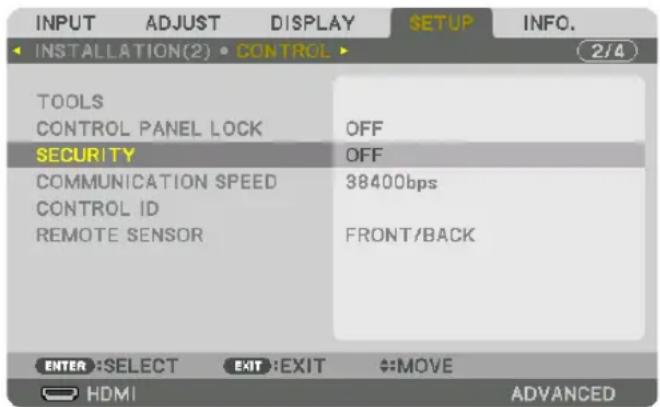
The OFF/ON menu will be displayed.
- Press the ▼ button to select [ON] and press the ENTER button.

The [SECURITY KEYWORD] screen will be displayed.
- Type your keyword in a combination of the four ▲▼◀▶ buttons and press the ENTER button.
NOTE: A keyword must be 4 to 10 digits in length.
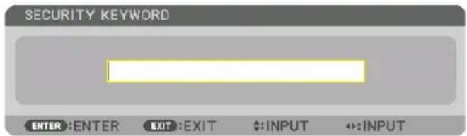
The [CONFIRM KEYWORD] screen will be displayed.
NOTE: Make a note of your password and store it in a safe place.
- Type your keyword in the same combination of ▲▼◀▶ buttons and press the ENTER button.

The confirmation screen will be displayed.
- Select [YES] and press the ENTER button.

The SECURITY function has been enabled.
To turn on the projector when [SECURITY] is enabled:
- Press the ⏻ button.
• If using the remote control, press the POWER ON button.
The projector will be turned on and display a message to the effect that the projector is locked.

flowchart
graph TD
    A["S SHIFT & POSITION"] --> B["SOURCE"]
    B --> C["3D REFORM"]
    C --> D["AUTO AS"]
    D --> E["EXIT"]
    E --> F["ENTER"]
    F --> G["MENU"]
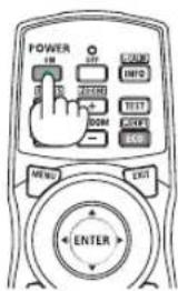
- Press the MENU button.

- Type in the correct keyword and press the ENTER button. The projector will display an image.

NOTE: The security disable mode is maintained until the main power is turned off or unplugging the power cord.
To disable the SECURITY function:
1. Press the MENU button.
The menu will be displayed.
2. Select [SETUP] → [CONTROL] → [SECURITY] and press the ENTER button.

The OFF/ON menu will be displayed.
3. Select [OFF] and press the ENTER button.

The SECURITY KEYWORD screen will be displayed.

4. Type in your keyword and press the ENTER button.
When the correct keyword is entered, the SECURITY function will be disabled.
NOTE: If you forget your keyword, contact your dealer. Your dealer will provide you with your keyword in exchange for your request code. Your request code is displayed in the Keyword Confirmation screen. In this example [NB52-YGK8-2VD6-K585-JNE6-EYA8] is a request code.
⑩ Projecting 3D videos
This projector supports 3D emitter and DLP-Link glasses.

CAUTION
Health precautions
Before use, please make sure to read any health precautions that may be stated in the operating manuals enclosed with the 3D eyewear and 3D video software (Blu-ray player, games, computer animation files, etc.).
Please take note of the following in order to avoid adverse health effects.
- Please do not use the 3D eyewear for purposes other than to watch 3D videos.
- Please keep a distance of at least 2 m away from the screen when watching videos. Watching a video too close to the screen will increase eye fatigue.
- Please do not watch videos continuously for a long period of time. Please take a 15 minutes' break after every hour of watching.
- Please consult a doctor before watching if you or any of your family members have a history of suffering from seizures caused by light sensitivity.
- Please stop watching immediately and take a rest when you feel physically unwell while watching (vomiting, giddiness, nausea, headaches, sore eyes, blurred vision, cramps and dumbness in the limbs, etc.). Please consult a doctor if the symptoms persist.
- Please watch a 3D video directly in front of the screen. If you watch a 3D video obliquely from the sides, this may result in physical and eye fatigue.
Procedure to watch 3D videos using this projector
Using a 3D emitter
This projector can be used to watch videos in 3D using commercially-available active shutter-type 3D eyewear. In order to synchronize the 3D video and eyewear, a commercially-available 3D emitter needs to be connected to the projector (on the projector side).
The 3D eyewear receives information from the 3D emitter and performs opening and closing on the left and right.
- The default factory setting is [OTHERS].
3D eyewear and 3D emitter preparations
Please use an active shutter-type 3D eyewear that conforms with the VESA standard.
A commercially-available RF type made by Xpand is recommended.
3D eyewear.....Xpand X105-RF-X2
3D emitter.....Xpand AD025-RF-X1
-
Connect your 3D emitter to the 3D SYNC terminal of the projector.
-
Switch on the projector.
-
Run the 3D video software.
The 3D video will be projected.
The default factory setting is [AUTO]. When 3D image is not projected, it may cause input signal does not contain 3D detection signal or it can not be detected by this projector. In this case, please set up the format manually.
(1) Press the MENU button.

The MENU will be displayed.
(2) Press the ▶ button, select [ADJUST], then press ENTER.
[PICTURE] will be highlighted.
(3) Use the ▶ button to select [3D SETTINGS].
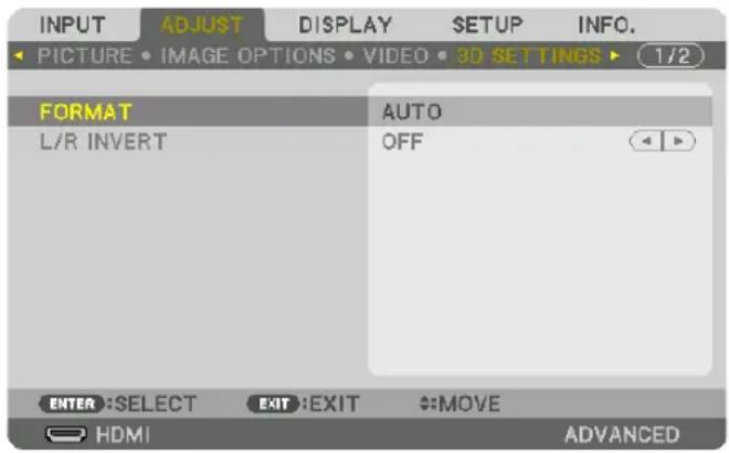
The [3D SETTINGS] screen will be displayed.
(4) Use the ▼ button to align the cursor with [FORMAT], then press ENTER.

The [FORMAT] screen will be displayed.
(5) Use the ▼/▲ buttons to align the cursor at one among format options, then press ENTER for setting it up.
The display will return to the [FORMAT] screen.
Press the MENU button to return to the original screen.
- The 3D caution message screen will be displayed when switching to a 3D video (default factory setting when shipped). Please read the “Health Precautions” on the previous page to watch videos in the correct manner. The screen will disappear after 60 seconds or when the ENTER button is pressed. (→ page 115)
4. Turn on the power supply of the 3D eyewear and wear the eyewear to watch the video.
A normal video will be shown when a 2D video is input.
To watch a 3D video in 2D, select [OFF(2D)] in the [FORMAT] screen mentioned above in (3).
NOTE:
- Upon switching to 3D image, the following functions will be cancelled and disabled. [BLANKING], [PIP/PICTURE BY PICTURE], [GEOMETRIC CORRECTION], [EDGE BLENDING] ([GEOMETRIC CORRECTION] and [EDGE BLENDING] adjustment values will be maintained.)
- The output may not automatically switch to a 3D video depending on the 3D input signal.
- Check the operating conditions described in the user manual of the Blu-ray player.
- Please connect the DIN terminal of the 3D emitter to the 3D SYNC of the main projector.
- The 3D eyewear allows videos to be viewed in 3D by receiving synchronized optical signals output from the 3D emitter.
As a result, the 3D image quality may be affected by conditions such as the brightness of the surroundings, screen size, viewing distance, etc. - When playing a 3D video software on a computer, the 3D image quality may be affected if the computer CPU and graphics chip performance are low. Please check the required operating environment of the computer that is stated in the operating manual attached to the 3D video software.
- Depending on the signal, [FORMAT] and [L/R INVERT] may not be able to be selected. Please change the signal in that case.
Using DLP® Link
Use DLP® Link glasses or other compatible commercially-available liquid crystal shutter spectacles.
- Connect a video device to the projector.
- Switch on the projector.
- Change [3D GLASSES] setting to [DLP® Link].

NOTE:
- If 3D content is played back on your computer and the performance is poor, it may be caused by the CPU or graphics chip. In this case you may have difficulty seeing the 3D images as they were intended. Check to see if your computer meets the requirements provided in your user's manual included with your 3D content.
- The DLP® Link compatible 3D eyeglasses allow you to view 3D images by receiving synch signals, which are included in left eye and right eye images, reflected from the screen. Depending on environments or conditions such as the ambient brightness, screen size or viewing distance, the 3D eyeglasses may fail to receive synch signals, causing poor 3D images.
- When the 3D mode is enabled, the Keystone correction range will be narrower.
- When the 3D mode is enabled, the following settings are invalid.
[WALL COLOR], [PRESET], [REFERENCE], [COLOR TEMPERATURE], [DYNAMIC CONTRAST], [Brilliant Color] - Signals other than those listed in "Compatible Input Signal List" on page 168 and 169 will be out of range or displayed in 2D.
When videos cannot be viewed in 3D
Please check the following points when videos cannot be viewed in 3D.
Please also read the operating manual attached to the 3D eyewear.
| Possible reasons Solutions | ||
| The selected signal does not support 3D output. Please change the video signal input to one that supports 3D. | ||
| The format for the selected signal is turned to [OFF(2D)]. | Please change the format in the on-screen menu to [AUTO] or a format that supports 3D. | |
| A eyewear that is not supported by the projector is being used. | Please purchase a commercially-available 3D eyewear or 3D emitter (recommended). (→ page 48) | |
| Please check the following points when a video cannot be viewed in 3D using a 3D eyewear that is supported by the projector. | ||
| The power supply of the 3D eyewear is turned off. Please turn on the power supply of the 3D eyewear. | ||
| The internal battery of the 3D eyewear is flat. Please charge or replace the battery. | ||
| The viewer is located too far away from the screen. Please get closer to the screen until the video can be seen in 3D. | ||
| Due to multiple 3D projectors working at the same time in the vicinity, the projectors may interfere with one another. Alternatively, there may be a bright light source near the screen. | Please maintain sufficient distance between the projectors. | |
| Please keep the light source away from the screen. | ||
| Please turn the L/R INVERT in the on-screen menu to [OFF]. | ||
| Please check the following points when videos played back on the computer cannot be viewed in 3D. | ||
| Settings on the computer are not compatible with 3D video playback. | Check to make sure that settings on the computer meet requirements for 3D video playback. | |
| Image resolution on the computer cannot be recognized by the projector as 3D video. | Change the image resolution on the computer to one that the projector can recognize as 3D video. | |
| The vertical scan rate on the computer cannot be recognized by the projector as 3D video. | Change the vertical scan rate on the computer to 60 Hz or 120 Hz. | |
| There is an obstacle between the optical receiver of the 3D eye-wear and the 3D emitter. | Please remove the obstacle. | |
| The 3D format of the 3D video contents is not supported. Please check with the company selling the 3D video contents. | ||
⑪ Controlling the Projector by Using an HTTP Browser
Overview
The HTTP Server function provides settings and operations for:
1. Setting for wired network (NETWORK SETTINGS)
To use wired LAN connection, connect the projector to the computer with a commercially available LAN cable. ( page 153)
2. Setting Alert Mail (ALERT MAIL)
When the projector is connected to a wired network, error messages will be sent via e-mail.
3. Operating the projector
Power on/off, selecting input, volume control, picture adjustments, and lens control are possible.
4. Setting PJLink PASSWORD, AMX BEACON, and CRESTRON.
Access to the HTTP server function is available:
- Start the Web browser on the computer via the network connected to the projector and enter the following URL :
http://
TIP: The factory default setting IP address is [DHCP ON].
NOTE:
- To use the projector in a network, consult with your network administrator about network settings.
- The display's or button's response can be slowed down or operation may not be accepted depending the settings of your network. Should this happen, consult your network administrator. The projector may not respond if its buttons are repeatedly pressed in rapid intervals. Should this happen, wait a moment and repeat. If you still can't get any response, turn off and back on the projector.
- If the PROJECTOR NETWORK SETTINGS screen does not appear in the web browser, press the Ctrl+F5 keys to refresh your web browser (or clear the cache).
- This projector uses “JavaScript” and “Cookies” and the browser should be set to accept these functions. The setting method will vary depending on the version of browser. Please refer to the help files and the other information provided in your software.
Preparation before Use
Connect the projector to a commercially available LAN cable before engaging in browser operations. ( page 153) Operation with a browser that uses a proxy server may not be possible depending on the type of proxy server and the setting method. Although the type of proxy server will be a factor, it is possible that items that have actually been set will not be displayed depending on the effectiveness of the cache, and the contents set from the browser may not be reflected in operation. It is recommended that a proxy server not be used unless it is unavoidable.
Handling of the Address for Operation via a Browser
Regarding the actual address that is entered for the address or entered to the URL column when operation of the projector is via a browser, the host name can be used as it is when the host name corresponding to the IP address of the projector has been registered to the domain name server by a network administrator, or the host name corresponding to the IP address of the projector has been set in the "HOSTS" file of the computer being used.
Example 1: When the host name of the projector has been set to "pj.nec.co.jp", access is gained to the network setting by specifying
http://pj.nec.co.jp/index.html for the address or the entry column of the URL.
Example 2: When the IP address of the projector is "192.168.73.1", access is gained to the network setting by specifying
http://192.168.73.1/index.html for the address or the entry column of the URL.
PROJECTOR ADJUSTMENT
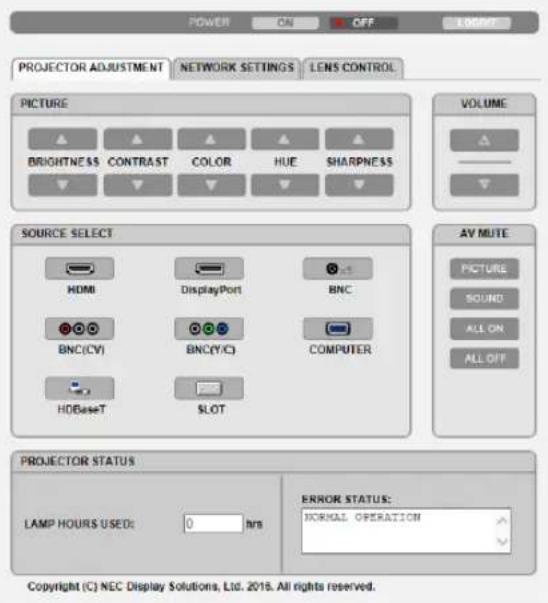
POWER: This controls the power of the projector.
ON ...... Power is switched on.
OFF ...... Power is switched off.
VOLUME: Can not be used for this device.
AV-MUTE: This controls the mute function of the projector.
PICTURE ON......Mutes the video.
PICTURE OFF......Cancels the video muting.
SOUND ON ....... Cannot be used for this device.
SOUND OFF ...... Cannot be used for this device.
ALL ON ...... Mutes the video functions.
ALL OFF...... Cancels the muting of the video functions.
PICTURE: Controls the video adjustment of the projector. BRIGHTNESS ▲ .... Increases the brightness adjustment value. BRIGHTNESS ▼ .... Decreases the brightness adjustment value. CONTRAST ▲.....Increases the contrast adjustment value. CONTRAST ▼.....Decreases the contrast adjustment value. COLOR ▲.....Increases the color adjustment value. COLOR ▼.....Decreases the color adjustment value. HUE ▲.....Increases the hue adjustment value. HUE ▼.....Decreases the hue adjustment value. SHARPNESS ▲ ..... Increases the sharpness adjustment value. SHARPNESS ▼ ..... Decreases the sharpness adjustment value.
- The functions that can be controlled will vary depending on the signal being input to the projector. (→ page 95)
SOURCE SELECT: This switches the input terminal of the projector.
HDMI ...... Switches to the HDMI IN terminal.
DisplayPort...... Switches to the DisplayPort IN.
BNC ...... Switch to BNC IN video input.
BNC(CV) ...... Switch to BNC (CV) video input.
BNC(Y/C) ...... Switch to BNC (Y/C) video input.
COMPUTER ...... Switches to the COMPUTER IN terminal.
HDBaseT...... Switch to image input sent from a transmission device that supports HDBaseT.
SLOT...... The projector switches to video input from the optional board when an optional board (sold separately) is equipped on.
PROJECTOR STATUS: This displays the condition of the projector.
LIGHT HOURS USED ......Displays how many hours the light module has been used.
ERROR STATUS......Displays the status of errors occurring within the projector.
LOG OFF: Logging off your projector and returning to the authentication screen (LOGON screen).
NETWORK SETTINGS

- SETTINGS
WIRED
| SETTING Set for wired LAN. | |
| APPLY Apply your settings to wired LAN. | |
| PROFILE 1/PROFILE 2 Two settings can be set for wired LAN connection. Select PROFILE 1 or PROFILE 2. | |
| DISABLE Turn off wired LAN connection | |
| DHCP ON Automatically assign IP address, subnet mask, and gateway to the projector from your DHCP server. | |
| DHCP OFF Set IP address, subnet mask, and gateway to the projector assigned by your network administrator. | |
| IP ADDRESS Set your IP address of the network connected to the projector. | |
| SUBNET MASK Set your subnet mask number of the network connected to the projector. | |
| GATEWAY Set the default gateway of the network connected to the projector. | |
| AUTO DNS ON DHCP server will automatically assign IP address of DNS server connected to the projector. | |
| AUTO DNS OFF Set your IP address of DNS server connected to the projector. |
• NAME
| PROJECTOR NAME Enter | a name for your projector so that your computer can identify the projector. A projector name must be 16 alphanumeric characters or less.TIP: Projector name will not be affected even when [RESET] is done from the menu. |
| HOST NAME Enter the host | stname of the network connected to the projector. A host name must be 15 alphanumeric characters or less. |
| DOMAIN NAME Enter the | domain name of the network connected to the projector. A domain name must be 60 alphanumeric characters or less. |
- ALERT MAIL
| ALERT MAIL | This option will notify your computer of error messages via e-mail when using wired LAN.Placing a checkmark will turn on the Alert Mail feature.Clearing a checkmark will turn off the Alert Mail feature.Sample of a message to be sent from the projector:Subject: [Projector] Projector InformationTHE COOLING FAN HAS STOPPED.[INFORMATION]PROJECTOR NAME: PX1004UL SeriesLIGHT HOURS USED: 0000[H] |
| SENDER'S ADDRESS Enter sender's address. | |
| SMTP SERVER NAME Enter the SMTP server name to be connected to the projector. | |
| RECIPIENT'S ADDRESS 1, 2, 3 | Enter your recipient's address. Up to three addresses can be entered. |
| TEST MAIL Send a test mail to check whether your settings are correct or notNOTE:If you execute a test, you may not receive an Alert mail. Should this happen, check if network settings are correct.If you entered an incorrect address in a test, you may not receive an Alert mail. Should this happen, check if the Recipient's Address is correct. | |
| SAVE Click this button to save your settings to the projector's memory. | |
• NETWORK SERVICE
| PJLink PASSWORD Set a | password for PJLink*. A password must be 32 characters or less. Do not forget your password. However, if you forget your password, consult with your dealer. |
| HTTP PASSWORD Set a | password for HTTP server. A password must be 10 characters or less.When a password is set up, you will be prompted for your user name (arbitrary) and password during LOGON. |
| AMX BEACON | Turn on or off for detection from AMX Device Discovery when connecting to the network supported by AMX's NetLinx control system.TIP:When using a device that supports AMX Device Discovery, all AMX NetLinx control system will recognize the device and download the appropriate Device Discovery Module from an AMX server Placing a checkmark will enable detecting the projector from AMX Device Discovery.Clearing a checkmark will disable detecting the projector from AMX Device Discovery. |
| Extron XTP Set for connecting this projector to the Extron XTP transmitter. Placing a checkmark will enable to connect with the XTP transmitter. Clearing a checkmark will disable to connect with the XTP transmitter. | |
NOTE: If you forget your password, contact your dealer. Please check 24 digits serial number (XXXX-XXXX-XXXX-XXXX-XXXX-XXXX) displayed on the column for the password.
*What is PJLink?
PJLink is a standardization of protocol used for controlling projectors of different manufacturers. This standard protocol is established by Japan Business Machine and Information System Industries Association (JBMIA) in 2005.
The projector supports all the commands of PJLink Class 1.
Setting of PJLink will not be affected even when [RESET] is done from the menu.
CRESTRON
- ROOMVIEW for managing from the computer.
| DISABLE Disables ROOMVIEW. |
| ENABLE Enables ROOMVIEW. |
- CRESTRON CONTROL for managing from the controller.
| DISABLE Disables CRESTRON CONTROL. |
| ENABLE Enables CRESTRON CONTROL. |
| IP ADDRESS Set your IP address of CRESTRON SERVER. |
| IP ID Set your IP ID of CRESTRON SERVER. |
• INFORMATION
| WIRED LAN Display a list of settings of wired LAN connection. |
| UPDATE Reflect settings when they are changed. |
LENS CONTROL

Copyright (C) NEC Display Solutions, Ltd. 2016. All rights reserved.
• CONTROL
| FOCUS | ◀/▶ | Adjust FOCUS of the projected image. |
| ZOOM | ◀/▶ | Finely adjusting the size of an image. |
| SHIFT | ▼▲◀▶ | Adjust the projected image's vertical and horizontal position. |
| HOME Return the lens shift position to the home position. | ||
| SHUTTER Turn off the light source temporarily. | ||
| ∅ SHUTTER | Turn on the light source. | |
| CALIB. Correct the adjustable zoom, focus and les shift range. | ||
- LENS MEMORY
| STORE Store the current adjusted values in memory for each input signal. | |
| MOVE Applies the adjusted values of LENS SHIFT, ZOOM, and FOCUS to the current signal. | |
| RESET | Return the adjusted valued to the last condition. |
• REF. LENS MEMORY
| PROFILE1/PROFILE2 Select a stored [PROFILE] number. | ||
| STORE Store each adjusted value of LENS SHIFT, ZOOM and FOCUS for the selected profile as the common values for every input signal. | ||
| MOVE Move the lens to the stored values of LENS SHIFT, ZOOM, and FOCUS for the selected profile. | ||
| RESET Reset selected [REF. LENS MEMORY] for the selected [PROFILE] to the default factory settings. | ||
| LOAD BY SIGNAL | OFF If | input signal is switched, the lens will not shift to the les shift, zoom and focus values for the selected [PROFILE] number. |
| ON If | input signal is switched, the lens will shift to the lens shift, zoom and focus values for the selected [PROFILE] number.If no adjusted values have been stored to [LENS MEMORY], the lens will apply [REF. LENS MEMORY] adjusted values. Alternatively, if no adjusted values have been stored to [REF. LENS MEMORY], the unit will return to the default factory settings. | |
| FORCED MUTE | OFF Not turn off the image during les shift. | |
| ON Turn off the image during les shift. | ||
• SHUTTER SETTINGS
| POWER ON SHUTTER | OPEN | When the power is turned on, the light source turns on and the picture is projected. |
| CLOSE | When the power is turned on, the light source does not turn on. | |
| PICTURE MUTE SHUT-TER | OPEN | The light source remains to on when the picture is turned off for switching the input terminals. |
| CLOSE | The light source turns off when the picture is turned off for switching the input terminals. | |
| FADE IN TIME Set how long the light will take to fade in after pressing the SHUTTER button. | ||
| FADE OUT TIME Set how long the light will take to fade out after pressing the SHUTTER button. | ||
TIP: The CRESTRON settings are required only for use with CRESTRON ROOMVIEW. For more information, visit http://www.crestron.com
⑫ Storing Changes for Lens Shift, Zoom, and Focus [LENS MEMORY]
The adjusted values can be stored in projector memory when using the LENS SHIFT, ZOOM and FOCUS buttons of the projector. Adjusted values can be applied to the signal you selected. This will eliminate the need to adjust lens shift, focus, and zoom at the time of source selection. There are two ways to save adjusted values for lens shift, zoom, and focus.
| Function name Description page | ||
| REF. LENS MEMORY Adjusted values common to all input signals. At the time of installation, two kinds of adjusted values can be stored.If no adjusted values are stored in [LENS MEMORY], adjusted values from the selected profile ([REF. LENS MEMORY]) will be applied for lens adjustment. | → page 120 | |
| LENS MEMORY Adjusted values for each input signal.Use the adjusted values for the signal with a different aspect ratio or resolution. The adjusted values can be applied at the time of source selection. | → page 103 | |
NOTE:
- For using the lens unit NP16FL, NP17ZL, NP18ZL, NP19ZL, NP20ZL, NP21ZL, and NP31ZL, be sure to carry out [LENS CALIBRATION] after replacing the lens unit. (→ page 18, 120)
- For the lens unit, NP16FL, the storable value as [LENS MEMORY] feature is for [FOCUS] only.
- The [LENS MEMORY] feature is not available for the lens unit, NP39ML.
To store your adjusted values in [REF. LENS MEMORY]:
1. Press the MENU button.

The menu will be displayed.
- Press the ▶ button to select [SETUP] and press the ENTER button.
- Press the ▶ button to select [INSTALLATION(2)].

- Press the ▼ button to select [REF. LENS MEMORY] and press the ENTER button.
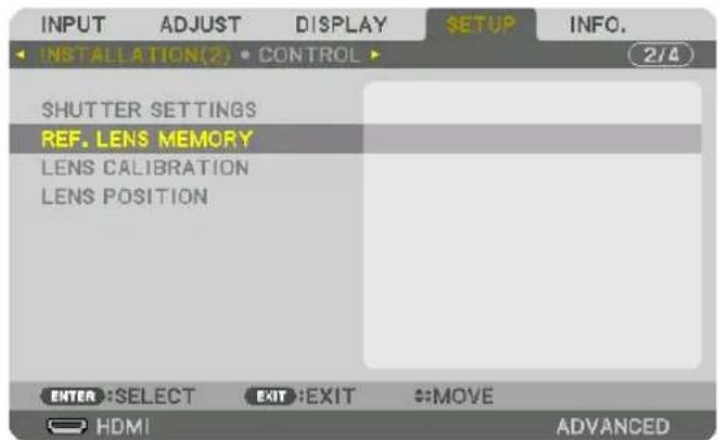
The [REF. LENS MEMORY] screen will be displayed.
- Make sure [PROFILE] is highlighted, then press the ENTER button.

The [PROFILE] selection screen appears.
- Press the ▼/▲ buttons to select the [PROFILE] number, then press the ENTER button.

Return to the [REF. LENS MEMORY] settings screen.
- Select [STORE] and press the ENTER button.

The confirmation screen will be displayed.
- Press the ◀ button to select and [YES] and press the ENTER button.

Select a [PROFILE] number and save the adjusted [LENS SHIFT], [ZOOM], and [FOCUS] values to it.
- The [FORCED MUTE] setting stops projection during lens shift. (→ page 120)
- Press the MENU button.
The menu will be closed.
TIP:
- To store adjusted values for each input source, use the Lens Memory function. (→ page 103)
To call up your adjusted values from [REF. LENS MEMORY]:
1. Press the MENU button.
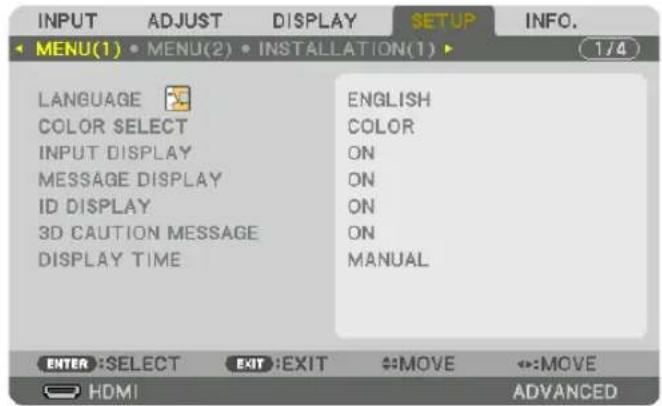
The menu will be displayed.
- Press the ▶ button to select [SETUP] and press the ENTER button.
- Press the ▶ button to select [INSTALLATION(2)].
- Press the ▼ button to select [REF. LENS MEMORY] and press the ENTER button.
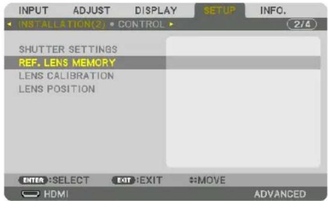
The [REF. LENS MEMORY] screen will be displayed.
5. Make sure [PROFILE] is highlighted, then press the ENTER button.
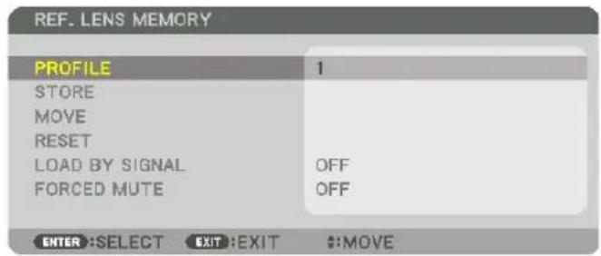
The [PROFILE] selection screen appears.
6. Press the ▼/▲ buttons to select the [PROFILE] number, then press the ENTER button.
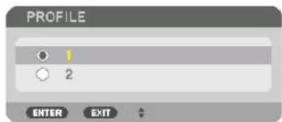
Return to the [REF. LENS MEMORY] settings screen.
7. Select [MOVE] and press the ENTER button.

The lens will shift based on the adjusted values stored in the selected [PROFILE].
- Press the ◀ button to select and [YES] and press the ENTER button.

The adjusted values will be applied to the current signal.
- Press the MENU button.
The menu will be closed.
TIP:
To call up the stored values from [LENS MEMORY]:
- From the menu, select [ADJUST] → [LENS MEMORY] → [MOVE] and press the ENTER button.

The confirmation screen will be displayed.
- Press the ◀ button to select and [YES] and press the ENTER button.
During projection, if the adjusted values for an input signal have been saved, the lens will shift. If not, the lens will shift according to the adjusted values stored in the selected [REF. LENS MEMORY] [PROFILE] number.
To automatically apply the stored values at the time of source selection:
- From the menu, select [SETUP] → [REF. LENS MEMORY] → [LOAD BY SIGNAL] and press the ENTER button.

- Press the ▼ button to select and [ON] and press the ENTER button.
This will move the lens automatically to the position at the time of source selection according to the adjusted values.

NOTE: The Lens Memory function may not produce a completely aligned image (due to tolerances in the lenses) using the adjusted values stored in the projector. After calling up and applying the stored values from the Lens Memory function, finely adjust the lens shift, zoom and focus to produce the best possible image.
4. Multi-Screen Projection
① Things that can be done using multi-screen projection
This projector can be used singly or arranged in multiple units for multi-screen projection. We will introduce an example using two projection screens here.
Case 1
Using a single projector to project two types of videos at the same time [PIP/PICTURE BY PICTURE]
Case 2
Using four projectors (resolution: WUXGA) to project video with a resolution of 2560 × 1600 pixels [TILING]
Case 1. Using a single projector to project two types of videos [PIP/PICTURE BY PICTURE]
Connection example and projection image
In the case of [PICTURE BY PICTURE] In the case of [PIP]
![SHARP PX1004UL - Case 1. Using a single projector to project two types of videos [PIP/PICTURE BY PICTURE] - 1](/content/2026/05/957502/images/461b36f325b2c402402f2fb2e63420644bd669bdc70f5376d05d8bb2e30cb6ac.jpg)
flowchart
graph TD
    A["Desktop"] --> B["Laptop"]
    B --> C["Video Device"]
    C --> D["Cityscape"]
    style A fill:#f9f,stroke:#333
    style B fill:#ccf,stroke:#333
    style C fill:#cfc,stroke:#333
    style D fill:#fcc,stroke:#333
![SHARP PX1004UL - Case 1. Using a single projector to project two types of videos [PIP/PICTURE BY PICTURE] - 2](/content/2026/05/957502/images/2415d7428ee5571220b078c31b70835f29e35ddc2a6062b799aa340a9694aec4.jpg)
flowchart
graph TD
    A["Desktop"] --> B["Laptop"]
    B --> C["Network Device"]
    C --> D["Laptop"]
    style A fill:#f9f,stroke:#333
    style B fill:#ccf,stroke:#333
    style C fill:#cfc,stroke:#333
    style D fill:#fcc,stroke:#333
On-screen menu operations
Display [DISPLAY] → [PIP/PICTURE BY PICTURE] → [MODE] screen in the on-screen menu and select [PIP] or [PICTURE BY PICTURE]. For details, please refer to "4-2 Displaying Two Pictures at the Same Time". (→ page 70)
Case 2. Using four projectors (resolution: WUXGA) to project videos with a resolution of 2560 × 1600 pixels [TILING]
Connection example and projection image
![SHARP PX1004UL - Case 2. Using four projectors (resolution: WUXGA) to project videos with a resolution of 2560 × 1600 pixels [TILING] - 1](/content/2026/05/957502/images/9e4e64e45e7023e6821a8aa4090c982b5fd88f160f45317606f95be36e89503e.jpg)
flowchart
graph TD
    A["Server"] --> B["Data Flow"]
    B --> C["Cityscape"]
    C --> D["Data Flow"]
    D --> E["Server"]
    style A fill:#f9f,stroke:#333
    style B fill:#ccf,stroke:#333
    style C fill:#cfc,stroke:#333
    style D fill:#fcc,stroke:#333
    style E fill:#cff,stroke:#333
On-screen menu operations
1 Four similar videos are displayed when four projectors are projected.
Please request the dealer to adjust the projection position of each projector.

natural_image
Four-panel cityscape photo showing a dense urban skyline with high-rise buildings along the waterfront (no visible text or signage)2 Operate the on-screen menu using the four respective projectors to divide the image into four portions.
Display [DISPLAY] → [MULTI SCREEN] → [PICTURE SETTING] Screen in the on-screen menu and select [TILING].
(1) In the screen for setting the number of horizontal units, select [2 UNITS]. (number of units in the horizontal direction)
(2) In the screen for setting the number of vertical units, select [2 UNITS]. (number of units in the vertical direction)
(3) In the screen for setting the horizontal order, select [1st UNIT] or [2nd UNIT].
(look at the screens, the one on the left is the [1st UNIT] while the one on the right is the [2nd UNIT])
(4) In the screen for setting the vertical order, select the [1st UNIT] or the [2nd UNIT].
(look at the screens, the one at the top is the [1st UNIT] while the one at the bottom is the [2nd UNIT])

natural_image
City skyline with modern skyscrapers and waterfront, no visible text or signage3 Adjust the lens shift of each projector to fine-tune the boundaries of the screen.
For further fine-tuning, adjust using [DISPLAY] → [EDGE BLENDING] in the on-screen menu for each projector. For details, please refer to "4-3 Displaying a Picture Using [EDGE BLENDING]".
(→ page 74)

natural_image
Panoramic cityscape with modern skyscrapers and a waterfront promenade (no visible text or signage)Things to note when installing projectors
- Leave 30 cm or over space between each projectors and between the intake vent and the wall for installing projectors side by side, so that air intake of the projectors are not obstructed. When the air intake and discharge outlet are obstructed, the temperature inside the projector will rise and this may result in a malfunction.
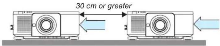
- Two projectors can be stacked on top of each other (STACK setting). (→ page 157) Do not attempt to directly stack three or more projectors. When the projectors are piled up on top of one another, they may fall down, resulting in damage and failure.

natural_image
Diagram showing three stacked devices with a red prohibition symbol overlay (no text or labels)• Installation example when using 3 or more projectors
The following installation is recommended when installing a combination of 3 or more projectors for multi-screen projection.
[Installation example]
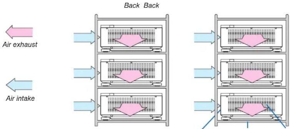
flowchart
graph LR
    A["Air intake"] --> B["Back Back"]
    C["Air exhaust"] --> B
    D["Air intake"] --> B
    B --> E["Three sequential processing units"]
    E --> F["Back Back"]
    style A fill:#f9f,stroke:#333
    style C fill:#f9f,stroke:#333
    style D fill:#f9f,stroke:#333
    style E fill:#ccf,stroke:#333
    style F fill:#ccf,stroke:#333
Exhaust ventIntake vent Cabinet

WARNING
Please request the dealer for special installation services such as when mounting the projector to the ceiling. Never carry out the installation by yourself. The projector may fall down and result in injury. Please use a sturdy cabinet that can withstand the weight of the projector for the installation. Please do not pile up the projectors directly on top of one another.
NOTE:
- For the range of the projection distance, please refer to the Appendix "Throw distance and screen size". (→ page 161)
② Displaying Two Pictures at the Same Time
The projector has a feature that allows you to view two different signals simultaneously. You have two modes: picture in picture (PIP) mode and picture by picture (PICTURE BY PICTURE) mode.
The projection video in the first screen display is known as the main display while the projection video that is called out subsequently is known as the sub-display.
Select the projection function under [DISPLAY] → [PIP/PICTURE BY PICTURE] → [MODE] in the on-screen menu (the default factory setting when shipped is PIP). (→ page 105)
- A single screen is projected when power is turned on.
Picture in Picture function (PIP)
A small sub-display is displayed inside the main display.
The sub-display can be set up and adjusted as follows. ( page 105)
- Select whether to display the sub-display at the top right, top left, bottom right or bottom left of the screen (the size of the sub-display can be selected and the position can be fine-tuned)
- Switch the main display with the sub-display
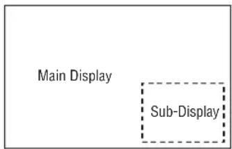
Picture by picture function (PICTURE BY PICTURE)
Display the main display and sub-display side by side.
The main display and sub-display can be set up and adjusted as follows. (→ page 105)
- Selecting the display boundary (ratio) of the main display and sub-display
- Switch the main display and sub-display
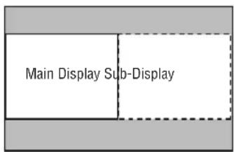
Input terminals that can be used for the main screen and sub-screen.
The main screen and sub-screen can provide the following input terminals.
- The main display and sub-display support computer signals up to WUXGA@60HzRB.
| Sub-Display or additional display | |||||||||
| HDMI DisplayPort BNC BNC(CV) BNC(Y/C) COMPUTER HDBaseT SLOT | |||||||||
| Main Display | HDMI | No | Yes Yes Yes Yes | No No | |||||
| DisplayPort | Yes Yes Yes Yes | ||||||||
| BNC | Yes Yes | No Yes Yes Yes Yes Yes Yes Yes Yes Yes Yes Yes Yes Yes Yes Yes Yes Yes Yes Yes Yes Yes Yes Yes Yes Yes Yes Yes Yes Yes Yes Yes Yes Yes Yes Yes Yes Yes Yes Yes Yes Yes Yes Yes Yes Yes Yes Yes Yes Yes Yes Yes Yes Yes Yes Yes Yes Yes Yes Yes Yes Yes Yes Yes Yes Yes Yes Yes Yes Yes Yes Yes Yes Yes Yes Yes Yes Yes Yes Yes Yes Yes Yes Yes Yes Yes Yes Yes Yes Yes Yes Yes Yes Yes Yes Yes Yes Yes Yes Yes Yes | No Yes Yes Yes Yes Yes Yes Yes Yes Yes Yes Yes Yes Yes Yes Yes Yes Yes Yes Yes Yes Yes Yes Yes Yes Yes Yes Yes Yes Yes Yes Yes Yes Yes Yes Yes Yes Yes Yes Yes Yes Yes Yes Yes Yes Yes Yes Yes Yes Yes Yes Yes Yes Yes Yes Yes Yes Yes Yes Yes Yes Yes Yes Yes Yes Yes Yes Yes Yes Yes Yes Yes Yes Yes Yes Yes Yes Yes Yes Yes Yes Yes Yes Yes Yes Yes Yes Yes Yes Yes Yes Yes Yes Yes Yes Yes Yes Yes | No | Yes Yes | ||||
| BNC(CV) | Yes Yes | ||||||||
| BNC(Y/C) | Yes Yes | ||||||||
| COMPUTER | Yes | Yes | No | Yes | Yes | No | Yes | Yes | |
| HDBaseT | No | Yes Yes Yes Yes | No No | ||||||
| SLOT | No | Yes Yes Yes Yes | No No | ||||||
NOTE:
- Some signals may not appear depending on the resolution.
- While utilizing PIP or PBP function, the HDMI-OUT terminal on the projector outputs the signal for the sub-display.
Projecting two screens
- Press the MENU button to display the on-screen menu and select [DISPLAY] → [PIP/PICTURE BY PICTURE].

This displays the [PIP/PICTURE BY PICTURE] screen in the on-screen menu.
- Select [SUB INPUT] using the ▼/▲ buttons, and press the ENTER button.
This displays the [SUB INPUT] screen.
- Select the input signal using the ▼/▲ buttons, and press the ENTER button.
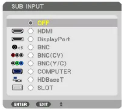
The [PIP] (PICTURE IN PICTURE) or [PICTURE BY PICTURE] screen set up under [MODE] is projected. (→ page 105)
- When the signal name is displayed in grey, this means that it cannot be selected.
-
The signal can also be selected by pressing the PIP/FREEZE button on the remote control.
-
Press the MENU button.
The on-screen menu will disappear.
- When returning to single screen, display the [PIP/PICTURE BY PICTURE] screen one more time and select [OFF] in the [SUB INPUT] screen of the Step 3.
TIP:
- During dual-screen projection, if the selected input is not supported by the sub-screen, the sub-screen will appear as a black screen.
Switching the main display with the sub-display and vice versa
- Press the MENU button to display the on-screen menu and select [DISPLAY] → [PIP/PICTURE BY PICTURE].

This displays the [PIP/PICTURE BY PICTURE] screen in the on-screen menu.
- Select [PICTURE SWAP] using the ▼/▲ buttons and then press the ENTER button.
Display the screen for switching the display positions.
- Select [ON] using the ▼ button and then press the ENTER button.
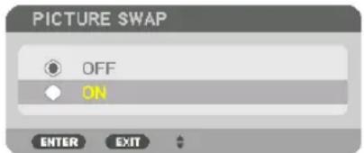
The video of the main display will switch with that of the sub-display.
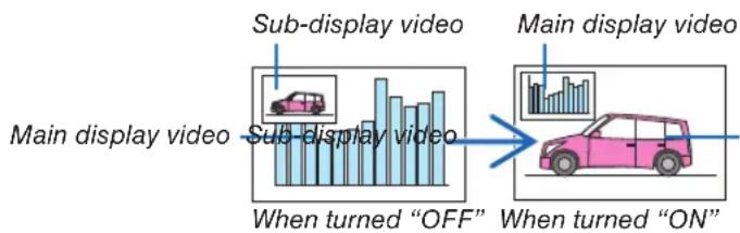
flowchart
graph LR
    A["Main display video"] --> B["When turned "OFF""]
    B --> C["Sub-display video"]
    C --> D["Main display video"]
    D --> E["When turned "ON""]
The signal output from the HDMI OUT terminal does not change even if the display positions are switched.
- Press the menu button.
The on-screen menu will disappear.
Restrictions
- The following operations are enabled only for the main display.
- Visual adjustments
- Video magnification / demaginification using the partial D-ZOOM/ZOOM +/- buttons.
However, magnification / demaginification is up to the boundary set in [PICTURE BY PICTURE].
- TEST PATTERN
- The following operations are enabled for both the main display and sub-display. These operations cannot be applied individually.
• Momentary deletion of video
- Video pause
- [PIP/PICTURE BY PICTURE] cannot be used when a 3D video is being displayed.
- When using the [PIP/PICTURE BY PICTURE] function, [CLOSED CAPTION] and [DYNAMIC CONTRAST] can be used.
- [PIP/PICTURE BY PICTURE] cannot be used when the signal input has a resolution of 1920 × 1200 or more.
- The HDMI OUT terminal has a repeater function. The output resolution is limited by the maximum resolution of the connected monitor and projector.
③ Displaying a Picture Using [EDGE BLENDING]
A high resolution video can be projected on an even bigger screen by combining multiple projectors on the left, right, top and bottom.
This projector is equipped with an “EDGE BLENDING Function” that makes the edges (boundaries) of the projection screen indistinguishable.
NOTE:
- For projector throw distances, refer to "Throw distance and screen size" on page 161.
- Before performing the Edge Blending function, place the projector in the correct position so that the image becomes square in the appropriate size, and then make optical adjustments (lens shift, focus, and zoom).
- Adjust the brightness of each projector using [REF. LIGHT ADJUST] under [LIGHT MODE]. After adjusting the brightness, you can keep the set brightness level by turning ON the [CONSTANT BRIGHTNESS] mode. In addition, use [REF. WHITE BALANCE] to adjust the [CONTRAST] and [BRIGHTNESS].
Before explaining use of the Edge Blending function
This section explains the case for “Example: Placing two projectors side by side”. As shown, the projected image on the left is referred to as “Projector A” and the projected image on the right is referred to “Projector B”. Unless otherwise specified hereinafter, the “projector” is used to mean both A and B.
Example: Placing two projectors side by side

Preparation:
- Turn on the projector and display a signal.
- In order to use one remote control for performing settings and adjustments to some projectors, set [ENABLE] for the CONTROL ID and assign ID for each projector, and then perform settings and adjustments to each.
Setting the overlap of projection screens
① Enable [EDGE BLENDING].
1. Press the MENU button.
The menu will be displayed.
2. Select [EDGE BLENDING].
The [EDGE BLENDING] screen will be displayed. Align the cursor with [MODE] and then press the ENTER button. The mode screen will be displayed.
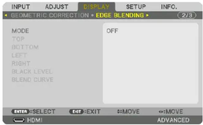
3. Select [MODE] → [ON] and press the ENTER button.

This enables the Edge Blending function. The following menu items are available:
[TOP], [BOTTOM], [LEFT], [RIGHT], [BLACK LEVEL], and [BLEND CURVE]
4. Select [RIGHT] for Projector A and [LEFT] for Projector B.
Press the ENTER button.
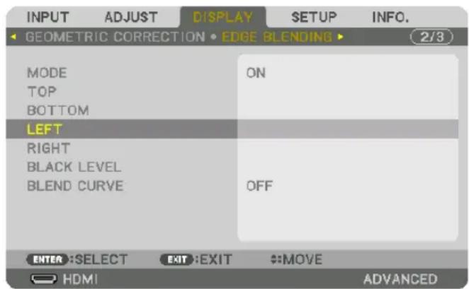
The following items are available:
[CONTROL], [MARKER], [RANGE], and [POSITION]
5. Select [CONTROL] → [ON] and press the ENTER button.

Each [TOP], [BOTTOM], [LEFT], [RIGHT], and [BLACK LEVEL] has its own [CONTROL], [MARKER], [RANGE], and [POSITION].
- For Projector A, set the [CONTROL] for the [TOP], [LEFT] and [BOTTOM] to [OFF]. Similarly for Projector B, set the [CONTROL] for the [TOP], [RIGHT] and [BOTTOM] to [OFF].
② Adjust [RANGE] and [POSITION] to determine an area of overlapped edges of images projected from each projector.
Turning on [MARKER] will display markers in magenta and green.
The magenta marker is used for [RANGE] and green one for [POSITION].
![SHARP PX1004UL - ② Adjust [RANGE] and [POSITION] to determine an area of overlapped edges of images projected from each projector. - 1](/content/2026/05/957502/images/6d1a6fe27edfd11787554901c2a51afefa92fbbc0998765fed1ad2f93b5aad7d.jpg)
flowchart
graph TD
    A["Original Cityscape"] --> B["Turn on [RIGHT"]]
    A --> C["Turn on [LEFT"]]
    B --> D["Magenta marker"]
    C --> E["Magenta marker"]
    D --> F["[RANGE"] (Determine an area of overlapped edges of images.)]
    E --> G["[POSITION"] (Determine the position of overlapped edges of images.)]
    F --> H["[POSITION"] (Determine the position of overlapped edges of images.)]
    G --> I["[POSITION"] (Determine the position of overlapped edges of images.)]
* The 2 screens are separated in the diagram for explanatory purposes.
1 Adjust [RANGE].
Use the ◀ or ▶ button to adjust the overlapped area.
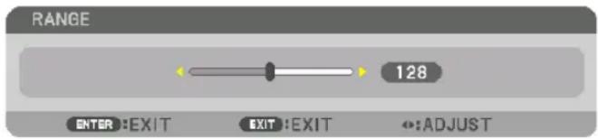
TIP:
- Adjust to overlap one projector' marker with the other projector's marker.
2 Adjust [POSITION].
Use the ◀ or ▶ button to align one edge with the other edge of overlapped images.

TIP:
- When displaying a signal with a different resolution, perform the Edge Blending function from the start.
- Setting of [MARKER] will not be saved and return to [OFF] when the projector is turned off.
- To display or hide the marker while the projector is running, turn on or off [MARKER] from the menu.
BLEND CURVE
Adjust the brightness of the overlapped section on the screens. According to the necessity, adjust the brightness of the overlapped section on the screens by the [BLEND CURVE] AND [BLACK LEVEL].
- Set the [MODE] to [ON] for selecting [BLEND CURVE] and [BLACK LEVEL].
Selecting an option for the [BLEND CURVE]
By controlling the graduation of the overlapped section on the screens, it makes the border on the projected screens inconspicuous. Select the optimal option among nine.
- On the On-Screen Menu, move the cursor onto the [DISPLAY] → [EDGE BLENDING] → [BLEND CURVE] and then press the ENTER. The option setting screen for the [BREND CURVE] is displayed on.
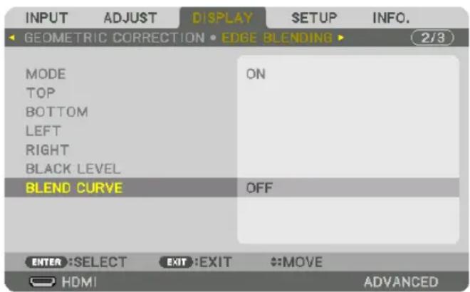
- Select one option among nine by ▲ or ▼.

Black Level Adjustment
This adjusts the black level of the overlapping area and the non-overlapping area of the multi-screen (EDGE BLENDING). Adjust the brightness level if you feel the difference is too large.
NOTE:
This function is enabled only when [MODE] is turned on.
Adjustable area varies depending on what combination of [TOP], [BOTTOM], [LEFT] and [RIGHT] are turned on.
Example: Adjusting the Black Level when placing two projectors side by side
![Width of overlap Adjust [CENTER] Adjust [CENTER] Projector A's image Projector B's image Adjust [CENTER-RIGHT] Adjust [CENTER-LEFT]](/content/2026/05/957502/images/2f7f18a079d8db38dda3e1732bbce6cbaa849f05141d5bfbe57cafe7c8159868.jpg)
1. Select [DISPLAY] → [EDGE BLENDING] → [BLACK LEVEL] and press the ENTER button.
The screen will switch to the black level adjustment screen.

2. Use the ▼ or ▲ button to select an item and use the ◀ or ▶ to adjust the black level.
Do this for the other projector if necessary.
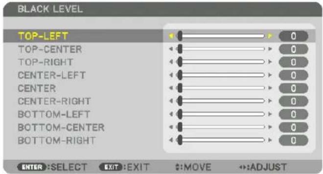
9-segmented portions for Black Level adjustment
The center projector
This function adjusts the brightness level of 9-segmented portions for the center projector and 4-segmented portions for the left bottom projector as shown below.

TIP:
- The number of black level division screens (maximum of nine divisions) changes depending on the number of edge blending positions selected (top, bottom, right, left). In addition, when the top / bottom and left / right ends are selected, the corner division screen appears.
- The edge blending width is the width set in the range and the corner is formed by the intersecting area of the top / bottom ends or left / right ends.
- The [BLACK LEVEL] can be adjusted to make it brighter only.
5. Using On-Screen Menu
① Using the Menus
NOTE: The on-screen menu may not be displayed correctly depending on input signal and the projector setting.
- Press the MENU button on the remote control or the projector cabinet to display the menu.
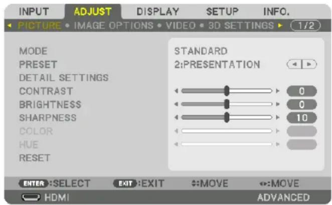
NOTE: The commands such as ENTER, EXIT, ▲▼, ◀▶ in the bottom show available buttons for your operation.
- Press the ◀▶ buttons on the remote control or the projector cabinet to display the submenu.
- Press the ENTER button on the remote control or the projector cabinet to highlight the top item or the first tab.
- Use the ▲▼ buttons on the remote control or the projector cabinet to select the item you want to adjust or set.
You can use the ◀▶ buttons on the remote control or the projector cabinet to select the tab you want.
- Press the ENTER button on the remote control or the projector cabinet to display the submenu window.
- Adjust the level or turn the selected item on or off by using the ▲▼◀▶ buttons on the remote control or the projector cabinet.
Changes are stored until adjusted again.
- Repeat steps 2-6 to adjust an additional item, or press the EXIT button on the remote control or the projector cabinet to quit the menu display.
NOTE: When a menu or message is displayed, several lines of information may be lost, depending on the signal or settings.
- Press the MENU button to close the menu.
To return to the previous menu, press the EXIT button.
② Menu Elements

Menu windows or dialog boxes typically have the following elements:
Highlight...... Indicates the selected menu or item.
Solid triangle ....Indicates further choices are available. A highlighted triangle indicates the item is active.
Tab......Indicates a group of features in a dialog box. Selecting on any tab brings its page to the front.
Radio button.....Use this round button to select an option in a dialog box.
Source....Indicates the currently selected source.
Menu mode ......Indicates the current menu mode: BASIC or ADVANCED.
Off Timer remaining time....Indicates the remaining countdown time when the [OFF TIMER] is preset.
Slide bar .....Indicates settings or the direction of adjustment.
LIGHT MODE symbol......Indicates [LIGHT MODE] is set.
Key Lock symbol ......Indicates the [CONTROL PANEL LOCK] is enabled.
Thermometer symbol ......Indicates the [LIGHT MODE] is forcibly set to [ECO] mode.
High symbol ....Indicates the built-in atmospheric pressure sensor detects height over 1200 m.
③ List of Menu Items
- Basic menu items are indicated by shaded area.
Some menu items are not available depending on the input source.
| Menu Item Default Options | ||||||
| INPUT | HDMI * | |||||
| DisplayPort * | ||||||
| BNC * | ||||||
| BNC(CV) * | ||||||
| BNC(Y/C) * | ||||||
| COMPUTER * | ||||||
| HDBaseT | ||||||
| SLOT | ||||||
| ENTRY LIST | ||||||
| TEST PATTERN | ||||||
| ADJUST | PICTURE | MODE STANDARD STANDARD, PROFESSIONAL | ||||
| PRESET * | HIGH-BRIGHT, PRESENTATION, VIDEO, MOVIE, GRAPHIC, sRGB, DICOM SIM., EDGE BLENDING | |||||
| DETAIL SETTINGS | GENERAL | |||||
| REFERENCE * | HIGH-BRIGHT, PRESENTATION, VIDEO, MOVIE, GRAPHIC, sRGB, DICOM SIM., EDGE BLENDING | |||||
| GAMMA CORRECTION*1 | SELECT DYNAMIC, NATURAL, REFERENCE | BLACK DETAIL | ||||
| SCREEN SIZE*2 | * | LARGE, MEDIUM, SMALL | ||||
| COLOR TEMPERATURE*3 | * | |||||
| DYNAMIC CONTRAST | * | OFF, ON | ||||
| LIGHT ADJUST | ||||||
| Brilliant Color | * | OFF, MEDIUM, HIGH | ||||
| WHITE BALANCE | ||||||
| CONTRAST R | 0 | |||||
| CONTRAST G | 0 | |||||
| CONTRAST B | 0 | |||||
| BRIGHTNESS R | 0 | |||||
| BRIGHTNESS G | 0 | |||||
| BRIGHTNESS B | 0 | |||||
| COLOR CORRECTION | ||||||
| RED | HUE SATURATION | 0 | ||||
| GREEN | HUE SATURATION | 0 | ||||
| BLUE | HUE SATURATION | 0 | ||||
| YELLOW | HUE SATURATION | 0 | ||||
| MAGENTA | HUE SATURATION | 0 | ||||
| CYAN | HUE SATURATION | 0 | ||||
| CONTRAST | 0 | |||||
| BRIGHTNESS | 0 | |||||
| SHARPNESS | 0 | |||||
| COLOR | 0 | |||||
| HUE | 0 | |||||
| RESET | ||||||
| IMAGE OPTIONS | CLOCK | * | ||||
| PHASE | * | |||||
| HORIZONTAL | * | |||||
| VERTICAL | * | |||||
| BLANKING | * | TOP, BOTTOM, LEFT, RIGHT | ||||
| OVERSCAN | AUTO | AUTO, 0[%], 5[%], 10[%] | ||||
| ASPECT RATIO | AUTO | (COMPUTER) AUTO, 4:3, 5:4, 16:9, 15:9, 16:10, FULL, NATIVE | ||||
| AUTO | COMPONENT/VIDEO/S-VIDEO) (SCREEN TYPE: 4:3) AUTO, 4:3, LETTERBOX, WIDE SCREEN, ZOOM | |||||
| AUTO | COMPONENT/VIDEO/S-VIDEO) (SCREEN TYPE: 16:9/16:10) AUTO, 4:3 WINDOW, LETTERBOX, WIDE SCREEN, FULL | |||||
| INPUT RESOLUTION*4 | * | - | ||||
* The asterisk (*) indicates that the default setting varies depending on the signal.
*1 The [GAMMA CORRECTION] item is available when an item other than [DICOM SIM.] is selected for [REFERENCE].
*2 The [SCREEN SIZE] item is available when [DICOM SIM.] is selected for [REFERENCE].
*3 When [PRESENTATION] or [HIGH-BRIGHT] is selected in [REFERENCE], the [COLOR TEMPERATURE] is not available.
*4 The [INPUT RESOLLUTION] item is available when either COMPUTER or BNC signal is selected as the input terminal.
| Menu Item Default Options | |||||
| ADJUST | VIDEO | NOISE REDUCTION | RANDOM NR OFF OFF, LOW, MEDIUM, HIGH | ||
| MOSQUITO NR OFF OFF, LOW, MEDIUM, HIGH | |||||
| BLOCK NR OFF OFF, LOW | |||||
| DEINTERLACE NORMAL NORMAL, MOVIE, STILL | |||||
| CONTRAST ENHANCEMENT | MODE AUTO OFF, AUTO, NORMAL | ||||
| GAIN | |||||
| SIGNAL TYPE AUTO AUTO, RGB, COMPONENT | |||||
| VIDEO LEVEL AUTO AUTO, NORMAL, ENHANCED, SUPER WHITE | |||||
| 3D SETTINGS | FORMAT AUTO | AUTO, OFF(2D), FRAME PACKING, SIDE BY SIDE(HALF), SIDE BY SIDE(FULL), TOP AND BOTTOM, FRAME ALTERNATIVE, LINE ALTERNATIVE | |||
| L/R INVERT OFF OFF, ON | |||||
| LENS MEMORY | STORE | ||||
| MOVE | |||||
| RESET | |||||
| DISPLAY | PIP/PICTURE BY PICTURE | SUB INPUT | OFF, HDMI, DisplayPort, BNC, BNC(CV), BNC(Y/C), COMPUTER, HDBaseT, SLOT | ||
| MODE PIP PIP, PICTURE BY PICTURE | |||||
| PICTURE SWAP | OFF OFF, ON | ||||
| PIP SETTING | START POSITION | TOP-LEFT | TOP-LEFT, TOP-RIGHT, BOTTOM-LEFT, BOTTOM-RIGHT | ||
| HORIZONTAL POSITION | |||||
| VERTICAL POSITION | |||||
| SIZE MEDIUM LARGE, MEDIUM, SMALL | |||||
| BORDER | |||||
| GEOMETRIC CORRECTION | MODE | OFF, KEYSTONE, CORNERSTONE, HORIZONTAL CORNER, VERTICAL CORNER, WARP, PC TOOL | |||
| KEYSTONE | HORIZONTAL | ||||
| VERTICAL | |||||
| TILT | |||||
| THROW RATIO | |||||
| CORNERSTONE | TOP-LEFT, TOP, TOP-RIGHT, LEFT, RIGHT, BOTTOM-LEFT, BOTTOM, BOTTOM-RIGHT | ||||
| HORIZONTAL CORNER | TOP-LEFT, TOP, TOP-RIGHT, LEFT, RIGHT, BOTTOM-LEFT, BOTTOM, BOTTOM-RIGHT | ||||
| VERTICAL CORNER | TOP-LEFT, TOP, TOP-RIGHT, LEFT, RIGHT, BOTTOM-LEFT, BOTTOM, BOTTOM-RIGHT | ||||
| WARP | TOP-LEFT, TOP, TOP-RIGHT, LEFT, RIGHT, BOTTOM-LEFT, BOTTOM, BOTTOM-RIGHT | ||||
| PC TOOL | OFF OFF, 1, 2, 3 | ||||
| RESET | |||||
| EDGE BLENDING | MODE | OFF OFF, ON | |||
| TOP | CONTROL | ON | OFF, ON | ||
| MARKER | ON | OFF, ON | |||
| RANGE | |||||
| POSITION | |||||
| BOTTOM | CONTROL | ON | OFF, ON | ||
| MARKER | ON | OFF, ON | |||
| RANGE | |||||
| POSITION | |||||
| LEFT | CONTROL | ON | OFF, ON | ||
| MARKER | ON | OFF, ON | |||
| RANGE | |||||
| POSITION | |||||
| RIGHT | CONTROL | ON | OFF, ON | ||
| MARKER | ON | OFF, ON | |||
| RANGE | |||||
| POSITION | |||||
| BLACK LEVEL | TOP-LEFT | ||||
| TOP-CENTER | |||||
| TOP-RIGHT | |||||
| CENTER-LEFT | |||||
| CENTER | |||||
| CENTER-RIGHT | |||||
| BOTTOM-LEFT | |||||
| BOTTOM-CENTER | |||||
| BOTTOM-RIGHT | |||||
| BLEND CURVE OFF OFF, 1, 2, 3, 4, 5, 6, 7, 8, 9 | |||||
| Menu Item Default Options | ||||||
| DISPLAY | MULTI SCREEN | WHITE BALANCE | MODE OFF OFF, ON | |||
| CONTRAST W | ||||||
| CONTRAST R | ||||||
| CONTRAST G | ||||||
| CONTRAST B | ||||||
| BRIGHTNESS W | ||||||
| BRIGHTNESS R | ||||||
| BRIGHTNESS G | ||||||
| BRIGHTNESS B | ||||||
| PICTURE SETTING | MODE OFF OFF, ZOOM, TILING | |||||
| ZOOM | HORIZONTAL ZOOM | |||||
| VERTICAL ZOOM | ||||||
| HORIZONTAL POSITION | ||||||
| VERTICAL POSITION | ||||||
| TILING | WIDTH 1 UNIT, 2 UNITS, 3 UNITS, 4 UNITS | |||||
| HEIGHT 1 UNIT, 2 UNITS, 3 UNITS, 4 UNITS | ||||||
| HORIZONTAL POSITION | 1st UNIT, 2nd UNIT, 3rd UNIT, 4th UNIT | |||||
| VERTICAL POSITION 1st UNIT, 2nd UNIT, 3rd UNIT, 4th UNIT | ||||||
| SETUP | MENU(1) | LANGUAGE ENGLISH | ENGLISH, DEUTSCH, FRANÇAIS, ITALIANO, ESPAÑOL, SVENSKA,日本語 | |||
| DANSK, PORTUGUES, ČESTINA, MAGYAR, POLSKI,NEDERLANDS, SUOMI | ||||||
| NORSK, TÜRKÇE, PYCCKIIЙ, ÖRDБІ, EЛЛУИКА, 中文, 한국어 | ||||||
| ROMÁNÁ, HRVATSKA, БЪЛГАРСКИ, INDONESIA, HÔNÍTÍRI, İINU,雑ぎゅう, 繁體中文, Tiếng Việt | ||||||
| COLOR SELECT COLOR COLOR, MONOCHROME | ||||||
| INPUT DISPLAY ON OFF, ON | ||||||
| MESSAGE DISPLAY ON OFF, ON | ||||||
| ID DISPLAY ON OFF, ON | ||||||
| 3D CAUTION MESSAGE ON OFF, ON | ||||||
| DISPLAY TIME | AUTO 45 SEC | MANUAL, AUTO 5 SEC, AUTO 15 SEC, AUTO 45 SEC | ||||
| MENU(2) | MENU ANGLE 0° 0°, 90°, 270° | |||||
| MENU POSITION | HORIZONTAL POSITION | 0 | -10-10 | |||
| VERTICAL POSITION | 0 | -10-10 | ||||
| RESET | ||||||
| INSTALLATION(1) | ORIENTATION | AUTO | AUTO, DESKTOP FRONT, CEILING REAR, DESKTOP REAR,CEILING FRONT | |||
| SCREEN TYPE | FREE | FREE, 4:3 SCREEN, 16:9 SCREEN, 16:10 SCREEN | ||||
| WALL COLOR | OFF | OFF, BLACKBOARD, BLACKBOARD (GRAY), LIGHT YELLOW,LIGHT GREEN, LIGHT BLUE, SKY BLUE, LIGHT ROSE, PINK | ||||
| FAN MODE | AUTO | AUTO, MIDDLE, HIGH | ||||
| LIGHT MODE | LIGHT MODE | NORMAL | NORMAL, ECO1, ECO2 | |||
| CONSTANT BRIGHTNESS | OFF OFF, ON | |||||
| REF. LIGHT ADJUST | 20-100% | |||||
| REF. WHITE BALANCE | CONTRAST R | |||||
| CONTRAST G | ||||||
| CONTRAST B | ||||||
| BRIGHTNESS R | ||||||
| BRIGHTNESS G | ||||||
| BRIGHTNESS B | ||||||
| 3D GLASSES | OTHERS | DLP® Link, OTHERS | ||||
| INSTALLATION(2) | SHUTTER SETTINGS | POWER ON SHUTTER | OPEN | OPEN, CLOSE | ||
| PICTURE MUTE SHUTTER | OPEN | OPEN, CLOSE | ||||
| FADE IN TIME | 0-10 sec. | |||||
| FADE OUT TIME | 0-10 sec. | |||||
| REF. LENS MEMORY | PROFILE | 1 | 1, 2 | |||
| STORE | ||||||
| MOVE | ||||||
| RESET | ||||||
| LOAD BY SIGNAL | OFF ON, OFF | |||||
| FORCED MUTE | OFF ON, OFF | |||||
| LENS CALIBRATION | ||||||
| LENS POSITION | HOME | |||||
| TYPE | NP39ML | |||||
| Menu Item Default Options | |||||||
| SETUP CONTROL | TOOLS | ADMINISTRATOR MODE | MENU MODE ADVANCED ADVANCED, BASIC | ||||
| NOT SAVE SETTING VALUES OFF OFF, ON | |||||||
| NEW PASSWORD | |||||||
| CONFIRM PASSWORD | |||||||
| PROGRAM TIMER | ENABLE OFF OFF, ON | ||||||
| SETTINGS | EDIT | ACTIVE OFF, ON | |||||
| DAY | |||||||
| TIME | |||||||
| FUNCTION POWER, INPUT, LIGHT MODE | |||||||
| ADVANCED SETTINGS | |||||||
| POWER OFF OFF, ON | |||||||
| INPUT HDMI | |||||||
| LIGHT MODE NORMAL NORMAL, ECO1, ECO2 | |||||||
| REPEAT OFF OFF, ON | |||||||
| DELETE | |||||||
| UP | |||||||
| DOWN | |||||||
| BACK | |||||||
| DATE AND TIME SETTINGS | TIME ZONE SETTINGS | GMT | -12:00, -11:30, -11:00, -10:30, -10:00, -09:30, -09:00, -08:30, -08:00, -07:30, -07:00, -06:30, -06:00, -05:30, -05:00, -04:30, -04:00, -03:30, -03:00, -02:30, -02:00, -01:30, -01:00, -00:30, 00:00, +00:30, +01:00, +01:30, +02:00, +02:30, +03:00, +03:30, +04:00, +04:30, +05:00, +05:30, +06:00, +06:30, +07:00, +07:30, +08:00, +08:30, +09:00, +09:30, +10:00, +10:30, +11:00, +11:30, +12:00, +12:30, +13:00 | ||||
| DATE MM/DD/YYYY | |||||||
| TIME HH:MM | |||||||
| INTERNET TIME SERVER | OFF OFF, ON | ||||||
| IP ADDRESS | |||||||
| UPDATE | |||||||
| SUMMER TIME SETTINGS | ENABLE OFF OFF, ON | ||||||
| MON(START) 1, 2, 3, 4, 5, 6, 7, 8, 9, 10, 11, 12 | |||||||
| DAY(START) | FIRST, SECOND, THIRD, FOURTH, LAST | ||||||
| SUN, MON, TUE, WED, THU, FRI, SAT | |||||||
| TIME(START) | |||||||
| MON(EXIT) 1, 2, 3, 4, 5, 6, 7, 8, 9, 10, 11, 12 | |||||||
| DAY(EXIT) | FIRST WEEK, SECOND WEEK, THIRD WEEK, FOURTH WEEK, LAST WEEK | ||||||
| SUN, MON, TUE, WED, THU, FRI, SAT | |||||||
| TIME(EXIT) | |||||||
| TIME DIFFERENCE | +01:00, +00:30, -00:30, -01:00 | ||||||
| MOUSE | (Note) Cannot be used for this device. | ||||||
| CONTROL PANEL LOCK | OFF OFF, ON | ||||||
| SECURITY | OFF OFF, ON | ||||||
| COMMUNICATION SPEED | 38400bps | 4800bps, 9600bps, 19200bps, 38400bps, 115200bps | |||||
| CONTROL ID | CONTROL ID NUMBER | 1 | 1-254 | ||||
| CONTROL ID | OFF OFF, ON | ||||||
| REMOTE SENSOR | FRONT/ BACK | FRONT/BACK, FRONT, BACK, HDBase-T | |||||
| SETUP | NETWORK SETTINGS | WIRED LAN | PROFILES DISABLE, PROFILE 1, PROFILE 2 | ||||
| DHCP OFF, ON | |||||||
| IP ADDRESS | 192.168.0.10 | ||||||
| SUBNET MASK 255.255.255.0 | |||||||
| GATEWAY 192.168.0.1 | |||||||
| AUTO DNS OFF, ON | |||||||
| DNS CONFIGURATION | |||||||
| RECONNECT | |||||||
| PROJECTOR NAME PROJECTOR NAME PX1004UL Series | |||||||
| DOMAIN | HOST NAME necpj | ||||||
| DOMAIN NAME | |||||||
| ALERT MAIL | ALERT MAIL OFF, ON | ||||||
| HOST NAME | |||||||
| DOMAIN NAME | |||||||
| SENDER'S ADDRESS | |||||||
| SMTP SERVER NAME | |||||||
| RECIPIENT'S ADDRESS 1 | |||||||
| RECIPIENT'S ADDRESS 2 | |||||||
| RECIPIENT'S ADDRESS 3 | |||||||
| TEST MAIL | |||||||
| NETWORK SERVICE | HTTP | NEW PASSWORD | |||||
| SERVER | CONFIRM PASSWORD | ||||||
| PJLink | NEW PASSWORD | ||||||
| CONFIRM PASSWORD | |||||||
| AMX | |||||||
| BEACON | OFF, ON | ||||||
| CRESTRON | ROOMVIEW OFF, ON | ||||||
| CRESTRONCONTROL (ENABLE,CONTROLLER IPADDRESS, IP ID) | |||||||
| Extron XTP | OFF, ON | ||||||
| SOURCE OPTIONS | AUTO ADJUST NORMAL OFF, NORMAL, FINE | ||||||
| COLOR SYSTEM | BNC(VIDEO) AUTO | AUTO, NTSC3.58, NTSC4.43, PAL, PAL-M, PAL-N, PAL60, SECAM | |||||
| BNC(Y/C) AUTO AUTO, NTSC3.58, NTSC4.43, PAL, PAL-M, PAL-N, PAL60, SECAM | |||||||
| DEFAULT INPUT SELECT | LAST | LAST, AUTO, HDMI, DisplayPort, BNC, BNC(CV), BNC(Y/C),COMPUTER, HDBaseT, SLOT | |||||
| CLOSED CAPTION | OFF | OFF, CAPTION1, CAPTION2, CAPTION3, CAPTION4, TEXT1, TEXT2,TEXT3, TEXT4 | |||||
| BACKGROUND | BLUE | BLUE, BLACK, LOGO | |||||
| POWER OPTIONS | STANDBY MODE | NORMAL | NORMAL, NETWORK STANDBY | ||||
| DIRECT POWER ON | OFF | OFF, ON | |||||
| AUTO POWER ON SELECT | OFF | OFF, HDMI, DisplayPort, COMPUTER, HDBaseT, SLOT | |||||
| AUTO POWER OFF | 1:00 | OFF, 0:05, 0:10, 0:15, 0:20, 0:30, 1:00 | |||||
| OFF TIMER | OFF | OFF, 0:30, 1:00, 2:00, 4:00, 8:00, 12:00, 16:00 | |||||
| SLOT POWER | PROJECTOR ON | ON | OFF, ON | ||||
| PROJECTOR STANDBY | ENABLE | DISABLE, ENABLE | |||||
| RESET | CURRENT SIGNAL | ||||||
| ALL DATA | |||||||
| ALL DATA (INCLUDING ENTRY LIST) | |||||||
| INFO. | USAGE TIME | LIGHT HOURS USED | |||||
| TOTAL CARBON SAVINGS | |||||||
| SOURCE(1) | INPUT TERMINAL | ||||||
| RESOLUTION | |||||||
| HORIZONTAL FREQUENCY | |||||||
| VERTICAL FREQUENCY | |||||||
| SYNC TYPE | |||||||
| SYNC POLARITY | |||||||
| SCAN TYPE | |||||||
| SOURCE NAME | |||||||
| ENTRY NO. | |||||||
| SOURCE(2) | SIGNAL TYPE | ||||||
| VIDEO TYPE | |||||||
| BIT DEPTH | |||||||
| VIDEO LEVEL | |||||||
| LINK RATE | |||||||
| LINK LANE | |||||||
| 3D FORMAT | |||||||
| SOURCE(3) | INPUT TERMINAL | ||||||
| RESOLUTION | |||||||
| HORIZONTAL FREQUENCY | |||||||
| VERTICAL FREQUENCY | |||||||
| SYNC TYPE | |||||||
| SYNC POLARITY | |||||||
| SCAN TYPE | |||||||
| SOURCE NAME | |||||||
| ENTRY NO. | |||||||
| SOURCE(4) | SIGNAL TYPE | ||||||
| VIDEO TYPE | |||||||
| BIT DEPTH | |||||||
| VIDEO LEVEL | |||||||
| LINK RATE | |||||||
| LINK LANE | |||||||
| 3D FORMAT | |||||||
| WIRED LAN | IP ADDRESS | ||||||
| SUBNET MASK | |||||||
| GATEWAY | |||||||
| MAC ADDRESS | |||||||
| VERSION(1) | FIRMWARE | ||||||
| DATA | |||||||
| SUB-CPU | |||||||
| OTHERS | DATE TIME | ||||||
| PROJECTOR NAME | |||||||
| MODEL NO. | |||||||
| SERIAL NUMBER | |||||||
| CONTROL ID (when [CONTROL ID] is set) | |||||||
| HDBaseT | SIGNAL QUALITY | ||||||
| OPERATION MODE | |||||||
| LINK STATUS | |||||||
| HDMI STATUS | |||||||
④ Menu Descriptions & Functions [INPUT]
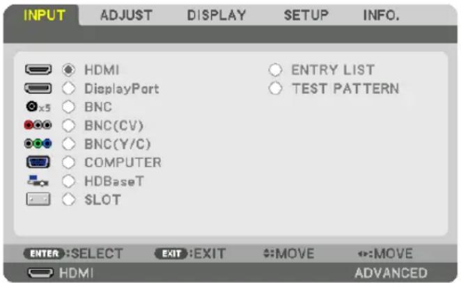
HDMI
This projects the video of the device connected to the HDMI IN terminal.
DisplayPort
This projects the video of the device connected to the Display Port IN terminal.
BNC
This projects the video of the device connected to the BNC IN video input terminal. (This projects the analog RGB signal or component signal.)
BNC(CV)
This projects the video of the device connected to the BNC (CV) video input terminal. (This projects the composite video signal.)
BNC(Y/C)
This projects the video of the device connected to the BNC (Y/C) video input terminal. (This projects the S-video signal.)
COMPUTER
This projects the video of the device connected to the COMPUTER IN terminal. (This projects the analog RGB signal or component signal.)
HDBaseT
Projecting the HDBaseT or WIRED LAN signal.
SLOT
Projects the picture via the optional board (sold separately) inserted into the SLOT.
ENTRY LIST
Displays a list of signals. See the following pages.
TEST PATTERN
Closes the menu and switches to the test pattern screen. Select the pattern using the ◀▶ buttons.
Using the Entry List
When any source adjustments are made, the adjustments are automatically registered in the Entry List. The (adjustment values of) registered signals can be loaded from the Entry List whenever necessary.
Up to 100 patterns can be registered in the Entry List. When 100 patterns have been registered in the Entry List, an error message is then displayed and no additional patterns can be registered. You should thus delete (adjustment values of) signals that are no longer needed.
Displaying the Entry list
1. Press the MENU button.
The menu will be displayed.
2. Press the ◀ or ▶ button to select [INPUT].
The INPUT list will be displayed.

3. Use the ◀, ▶, ▲, or ▼ to select [ENTRY LIST] and press the ENTER button.
The ENTRY LIST windows will be displayed.
If the ENTRY LIST window is not displayed, switch the menu to [ADVANCED].
To switch the menu between [ADVANCED] and [BASIC], select [SETUP] → [CONTROL] → [TOOLS] → [ADMINISTRATOR MODE] → [MENU MODE]. (→ page 121)

Entering the currently projected signal into the Entry List [STORE]
- Press the ▲ or ▼ button to select any number.
- Press the ◀ or ▶ button to select [ ↓ (STORE)] and press the ENTER button.
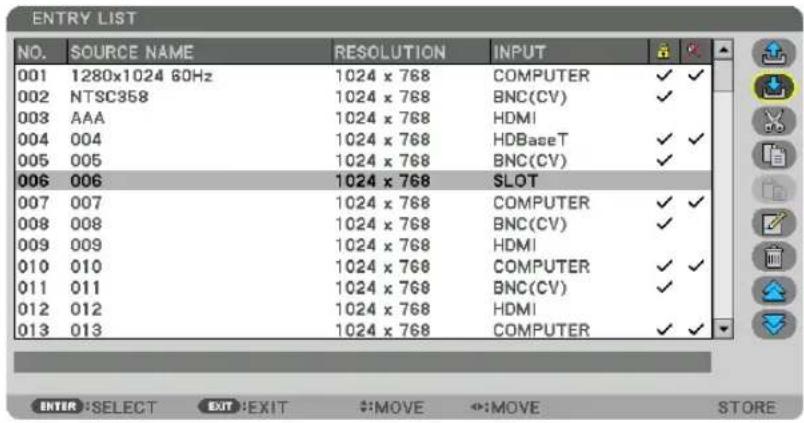
Calling up a signal from the Entry List [ (LOAD)]
Press the ▲ or ▼ button to select a signal and press the ENTER button.
Editing a signal from the Entry List [EDIT]
- Press the ▲ or ▼ button to select a signal you wish to edit.
- Press the ◀, ▶, ▲, or ▼ button to select [ (EDIT)] and press the ENTER button.
The Edit window will be displayed.

| SOURCE NAME Enter a signal name. Up to 18 alphanumeric characters can be used. | |
| INPUT The input terminal can be changed. Switching between HDMI/DisplayPort/BNC/BNC (CV)/BNC (Y/C)/Computer/HDBaseT/SLOT is possible. | |
| LOCK | Set so that the selected signal cannot be deleted when [INLL DELETE)] is executed.The changes made after LOCK execution cannot be saved. |
| SKIP | Set so that the selected signal will be skipped during auto search. |
- Set the above items and select [OK] and press the ENTER button.
NOTE: The input terminal cannot be changed to the currently projected signal.
Cutting a signal from the Entry List [ (CUT)]
- Press the ▲ or ▼ button to select a signal you wish to delete.
- Press the ◀, ▶, ▲, or ▼ button to select [ (CUT)] and press the ENTER button.
The signal will be deleted from the Entry List and the deleted signal will be displayed on the clipboard at the bottom of the Entry List.
NOTE:
- The currently projected signal cannot be deleted.
- When the locked signal is selected, it will be displayed in gray which indicates it is not available.
TIP:
• Data on the clipboard can be passed onto the Entry List.
• Data on the clipboard will not be lost after the Entry List is closed.
Copying and pasting a signal from the Entry List [ (COPY)] / [ (PASTE)]
- Press the ▲ or ▼ button to select a signal you wish to copy.
- Press the ◀, ▶, ▲, or ▼ button to select [ (COPY)] and press the ENTER button.
The copied signal will be displayed on the clipboard at the bottom of the Entry List.
- Press the ◀ or ▶ button to move to the list.
- Press the ▲ or ▼ button to select a signal.
- Press the ◀, ▶, ▲, or ▼ button to select [ (PASTE)] and press the ENTER button.
Data on the clipboard will be pasted to the signal.
Deleting all the signals from the Entry List [ALL DELTE)]
- Press the ◀, ▶, ▲, or ▼ button to select [ (ALL DELETE)] and press the ENTER button.
The confirmation message will be displayed. - Press the ◀ or ▶ button to select [YES] and press the ENTER button.
NOTE: The locked signal cannot be deleted.
⑤ Menu Descriptions & Functions [ADJUST]
[PICTURE]

[MODE]
This function allows you to determine how to save settings for [DETAIL SETTINGS] of [PRESET] for each input.
STANDARD...... Saves settings for each item of [PRESET] (Preset 1 through 8)
PROFESSIONAL.....Saves all the settings of [PICTURE] for each input.
NOTE:
- When [TEST PATTERN] is displayed, [MODE] cannot be selected.
[PRESET]
This function allows you to select optimized settings for your projected image.
You can adjust neutral tint for yellow, cyan or magenta.
There are eight factory presets optimized for various types of images. You can also use [DETAIL SETTINGS] to set user adjustable settings to customize each gamma or color.
Your settings can be stored in [PRESET 1] to [PRESET 8].
HIGH-BRIGHT.....Recommended for use in a brightly lit room.
PRESENTATION ..... Recommended for making a presentation using a PowerPoint file.
VIDEO ...... Recommended for typical TV program viewing.
MOVIE ...... Recommended for movies.
GRAPHIC ...... Recommended for graphics.
sRGB ...... Standard color values
DICOM SIM. ...... Recommended for DICOM simulation format.
EDGE BLENDING ... Recommended for edge blending.
NOTE:
- The [DICOM SIM.] option is for training/reference only and should not be used for actual diagnosis.
- DICOM stands for Digital Imaging and Communications in Medicine. It is a standard developed by the American College of Radiology (ACR) and the National Electrical Manufacturers Association (NEMA).
The standard specifies how digital image data can be moved from system to system. - Adjustment may not work depending on input signal.
[DETAIL SETTINGS]



[GENERAL]
Storing Your Customized Settings [REFERENCE]
This function allows you to store your customized settings in [PRESET 1] to [PRESET 8].
First, select a base preset mode from [REFERENCE], then set [GAMMA CORRECTION] and [COLOR TEMPERATURE].
HIGH-BRIGHT.....Recommended for use in a brightly lit room.
PRESENTATION ..... Recommended for making a presentation using a PowerPoint file.
VIDEO ...... Recommended for typical TV program viewing.
MOVIE ...... Recommended for movies.
GRAPHIC ...... Recommended for graphics.
sRGB ...... Standard color values.
DICOM SIM. ...... Recommended for DICOM simulation format.
EDGE BLENDING ... Recommended for edge blending.
Selecting Gamma Correction Mode [GAMMA CORRECTION]
Each mode in [SELECT] corrects color tone of projected image and is recommended for:
DYNAMIC ...... Creates a high-contrast picture.
NATURAL......Natural reproduction of the picture.
BLACK DETAIL.....Emphasizes detail in dark areas of the picture.
In [REFERENCE], it adjusts corrected value for projected image. Higher value means deeper correction.
NOTE: This function is not available when [DICOM SIM.] is selected for [DETAIL SETTINGS].
Selecting Screen Size for DICOM SIM [SCREEN SIZE]
This function will perform gamma correction appropriate for the screen size.
LARGE...... For screen size of 150"
MEDIUM......For screen size of 100"
SMALL......For screen size of 50"
NOTE:
- This function is available only when [DICOM SIM.] is selected for [DETAIL SETTINGS].
- Correction value is changed depending on projection images.
Adjusting Color Temperature [COLOR TEMPERATURE]
This option allows you to select the color temperature of your choice.
A value between 5000 K and 10500 K can be set in a 500 K unit.
NOTE:
- When [HIGH-BRIGHT] is selected in [REFERENCE], this function is not available.
- When [PRESENTATION] is selected in [REFERENCE], the selectable range for [COLOR TEMPERATURE] is 3 levels, 0, 1, and 3.
Adjusting Brightness and Contrast [DYNAMIC CONTRAST]
If [ON] is selected, the most optimal contrast ratio is used according to the picture.
NOTE:
- Depending on the conditions, projector settings such as [DYNAMIC CONTRAST] may not be able to be selected.
Adjusting Brightness [LIGHT ADJUST]
Brightness can be adjusted in 1% increments from 20 to 100%. The adjustment is effective when [NORMAL] is selected for [LIGHT MODE] and [PROFESSIONAL] is selected for [MODE].
[Brilliant Color]
Selects the brightness of the color white.
Selecting options from [MEDIUM] to [HIGH] increases the brightness of the color white.
NOTE:
- If under [REFERENCE], [HIGH-BRIGHT] or [PRESENTATION] are selected, [BrilliantColor] cannot be changed.
Adjusting White Balance [WHITE BALANCE]
This allows you to adjust the white balance. Contrast for each color (RGB) to adjust the white level of the screen; Brightness for each color (RGB) is used to adjust the black level of the screen.
[COLOR CORRECTION]
Corrects the color for all signals.
Adjusts the tone for the colors red, green, blue, yellow, magenta and cyan.
| RED HUE + Direction Magenta direction | ||
| - Direction Yellow direction | ||
| SATURATION + Direction Vivid | ||
| - Direction Weak | ||
| GREEN HUE | + Direction Yellow direction | |
| - Direction Cyan direction | ||
| SATURATION + Direction Vivid | ||
| - Direction Weak | ||
| BLUE HUE | + Direction Cyan direction | |
| - Direction Magenta direction | ||
| SATURATION + Direction Vivid | ||
| - Direction Weak | ||
| YELLOW HUE | + Direction Red direction | |
| - Direction Green direction | ||
| SATURATION | + Direction Vivid | |
| - Direction Weak | ||
| MAGENTA HUE | + Direction Blue direction | |
| - Direction Red direction | ||
| + Direction Vivid | ||
| - Direction Weak | ||
| CYAN HUE | + Direction Green direction | |
| - Direction Blue direction | ||
| SATURATION | + Direction Vivid | |
| - Direction Weak | ||
[CONTRAST]
Adjusts the intensity of the image according to the incoming signal.
[BRIGHTNESS]
Adjusts the brightness level or the back raster intensity.
[SHARPNESS]
Controls the detail of the image.
[COLOR]
Increases or decreases the color saturation level.
[HUE]
Varies the color level from +/- green to +/- blue. The red level is used as reference.
| Input signal CONTRAST BRIGHTNESS | SHARPNESS | COLOR HUE | |||
| RGB system of “COMPUTER/Display-Port/HDMI/HDBaseT” | Yes Yes | Yes No No | |||
| COMPONENT system of “COMPUTER/DisplayPort/HDMI/HDBaseT” | Yes Yes | Yes Yes Yes | |||
| Composite Video/S-Video Yes Yes Yes | Yes Yes |
Yes = Adjustable, No = Not adjustable
NOTE:
- When [TEST PATTERN] is displayed, [CONTRAST], [BRIGHTNESS], [SHARPNESS], [COLOR] and [HUE] cannot be adjusted.
[RESET]
The settings and adjustments for [PICTURE] will be returned to the factory settings with the exception of the following; Preset numbers and [REFERENCE] within the [PRESET] screen. The settings and adjustments under [DETAIL SETTINGS] within the [PRESET] screen that are not currently selected will not be reset.
[IMAGE OPTIONS]

Adjusting Clock and Phase [CLOCK/PHASE]
This allows you to manually adjust CLOCK and PHASE.
![SHARP PX1004UL - Adjusting Clock and Phase [CLOCK/PHASE] - 1](/content/2026/05/957502/images/e7c3f48224b3946290e573214cd3a52cd03cc9c3336dbc2f6b8d724c5e4362cf.jpg)
natural_image
Two-step diagram showing transformation of geometric shapes (circle, square, triangle) from a blank canvas to a window with a blue arrow indicating direction.CLOCK..... Use this item to fine tune the computer image or to remove any vertical banding that might appear. This function adjusts the clock frequencies that eliminate the horizontal banding in the image.
This adjustment may be necessary when you connect your computer for the first time.
![SHARP PX1004UL - Adjusting Clock and Phase [CLOCK/PHASE] - 2](/content/2026/05/957502/images/57b86bca205730396083bfb17d7e2dc3a1a09ce0cc7aeb53d647828351c60217.jpg)
natural_image
Two-step diagram showing transformation from a blank canvas to a gray geometric shapes (circle, square, triangle) on a canvas, with no text or symbols present.PHASE..... Use this item to adjust the clock phase or to reduce video noise, dot interference or cross talk. (This is evident when part of your image appears to be shimmering.)
Use [PHASE] only after the [CLOCK] is complete.
NOTE: The [CLOCK] and [PHASE] items are available for RGB signals only.
Adjusting Horizontal/Vertical Position [HORIZONTAL/VERTICAL]
Adjusts the image location horizontally and vertically.
![SHARP PX1004UL - Adjusting Horizontal/Vertical Position [HORIZONTAL/VERTICAL] - 1](/content/2026/05/957502/images/b469b65fe3464f2f5a9f240c5bf7ba26772f5f3ca8fa34ee0e73e0440b3c3e67.jpg)
flowchart
graph TD
    A["Rectangle with circles and triangles"] --> B["Rectangle with circles and triangles"]
    C["Rectangle with circles and triangles"] --> D["Rectangle with circles and triangles"]
- An image can be distorted during the adjustment of [CLOCK] and [PHASE]. This is not malfunction.
- The adjustments for [CLOCK], [PHASE], [HORIZONTAL], and [VERTICAL] will be stored in memory for the current signal. The next time you project the signal with the same resolution, horizontal and vertical frequency, its adjustments will be called up and applied.
To delete adjustments stored in memory, from the menu, you select [RESET] → [CURRENT SIGNAL] and reset the adjustments.
[BLANKING]
Adjusts the display range (blanking) at the top, bottom, left and right edges of the input signal.
![SHARP PX1004UL - [BLANKING] - 1](/content/2026/05/957502/images/ece66f213aa8d9d1400fb08213c80dd84c800121fb9a6d79d8462e05eaf4b6f0.jpg)
natural_image
Pure geometric diagram with a circle inside a square frame and directional arrows, no text or symbols present.Selecting Overscan Percentage [OVERSCAN]
Select overscan percentage (Auto, 0%, 5% and 10%) for signal.

NOTE:
• The [OVERSCAN] item is not available:
- when [NATIVE] is selected for [ASPECT RATIO].
Selecting the Aspect Ratio [ASPECT RATIO]
Use this function to select the screen's lateral:longitudinal aspect ratio.
Select the screen type (4:3 screen, 16:9 screen or 16:10 screen) in the [INSTALLATION(1)] before setting the aspect ratio. (→ page 117)
The projector automatically identifies the signal being input and sets the optimum aspect ratio.
For Computer signal

For Component/Video/S-Video signals
When the screen type is set to 4:3 When the screen type is set to 16:9 or 16:10


| Resolution Aspect Ratio | ||
| VGA 640 × 480 | 4:3 | |
| SVGA | 800 × 600 4:3 | |
| XGA | 1024 × 768 4:3 | |
| WXGA | 1280 × 768 15:9 | |
| WXGA | 1280 × 800 16:10 | |
| HD(FWXGA) | 1366 × 768 approx. | 16:9 |
| WXGA+ 1440 × | 900 16:10 | |
| SXGA | 1280 × 1024 5:4 | |
| SXGA+ | 1400 × 1050 4:3 | |
| WXGA++ | 1600 × 900 16:9 | |
| UXGA | 1600 × 1200 4:3 | |
| WSXGA+ | 1680 × 1050 16:10 | |
| FHD(1080P) | 1920 × 1080 16:9 | |
| WUXGA | 1920 × 1200 16:10 | |
| WQXGA | 2560 × 1600 16:10 | |
| Options Function | |
| AUTO | The projector will automatically determine the incoming signal and display it in its aspect ratio.The projector may erroneously determine the aspect ratio depending on its signal. If this occurs, select the appropriate aspect ratio from the following. |
| 4:3 The image is displayed in 4:3 aspect ratio. | |
| 5:4 The image is displayed in 5:4 aspect ratio | |
| 16:9 The image is displayed in 16:9 aspect ratio | |
| 15:9 The image is displayed in 15:9 aspect ratio | |
| 16:10 The image is displayed in 16:10 aspect ratio | |
| NATIVE | The projector displays the current image in its true resolution when the incoming computer signal has a lower or higher resolution than the projector's native resolution. (→ page 3)When the incoming computer signal has a higher resolution than the projector's native resolution, the center of an image will be displayed. |
| LETTER BOX | The image of a letterbox signal (16:9) is stretched equally in the horizontal and vertical directions to fit the screen.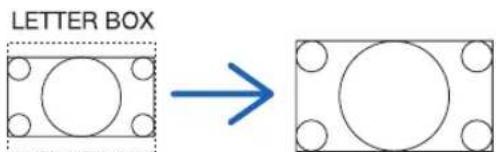 |
WIDE SCREEN The image of a squeeze signal(16:9) is stretched left and right in 16:9.Squeeze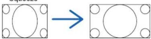 | |
ZOOM The image of a squeeze signal (16:9) is stretched left and right in 4:3.Parts of the displayed image are cropped at the left and right edges and therefore not visible.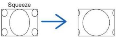 | |
| FULL Project to full screen size. | |
TIP:
- Image position can be adjusted vertically using [POSITION] when the [16:9], [15:9], or [16:10] aspect ratios are selected.
- The term “letterbox” refers to a more landscape-oriented image when compared to a 4:3 image, which is the standard aspect ratio for a vide source.
The letterbox signal has aspect ratios with the vista size "1.85:1" or cinema scope size "2.35:1" for movie film.
- The term "squeeze" refers to the compressed image of which aspect ratio is converted from 16:9 to 4:3.
[INPUT RESOLUTION]
The resolution is assigned automatically when the resolution of the input signal from the computer video input terminal or BNC video input terminal (analog RGB) cannot be distinguished.
[VIDEO]

Using Noise Reduction [NOISE REDUCTION]
When projecting a video image, you can use the [NOISE REDUCTION] function to reduce the screen noise (roughness and distortion). This device is equipped with three types of noise reduction functions. Select the function according to the type of noise. Depending on the noise level, the noise reduction effect can be set to [OFF], [LOW], [MEDIUM] or [HIGH]. [NOISE REDUCTION] can be selected for SDTV, HDTV signal and component signal input.
RANDOM NR ...... Reduces flickering random noise in an image.
MOSQUITO NR ..... Reduces mosquito noise that appears around the edges of an image during Blu-ray playback.
BLOCK NR ...... Reduces block noise or mosaic-like patterns by selecting ON.
Selecting Interlaced Progressive Conversion Process Mode [DEINTERLACE]
This function allows you to select an interlaced-to-progressive conversion process for video signals.
NORMAL..... Automatically distinguishes a moving image from a static image to create a distinct image. Please select [MOVIE] if there are any obvious jitter and noises.
MOVIE ...... Select when projecting moving images. This is suitable for signals with a lot of jitter and noise.
STILL...... Select when projecting static images. The video will flicker when a moving image is projected.
NOTE: This function is not available with RGB signals.
[CONTRAST ENHANCEMENT]
Using the characteristics of the human eye, a picture quality with a sense of contrast and resolution is achieved.
OFF ...... Contrast enhancement is switched off.
AUTO.... Contrast and picture quality are automatically improved using the suite vision function.
NORMAL.....Adjust the gain manually.
[SIGNAL TYPE]
Selection of RGB and component signals. Normally, this is set to [AUTO]. Please change the setting if the color of the image remains unnatural.
AUTO ...... Automatically distinguishes RGB and component signals.
RGB ...... Switches to the RGB input.
COMPONENT......Switches to the component signal input.
[VIDEO LEVEL]
Selection of the video signal level when connecting an external device to the HDMI IN terminal, DisplayPort input terminal, and HDBaseT input terminal of the projector.
AUTO .... The video level is switched automatically based on the information from the device outputting the signal.
Depending on the connected device, this setting may not be made properly. In this case, switch to [NORMAL" or "ENHANCED" from the menu and view with the optimum setting.
NORMAL......This disables the enhanced mode.
ENHANCED ...... This improves the image's contrast, expressing the dark and light sections more dynamically.
SUPER WHITE......The video contrast is improved and the dark areas appear more dynamic.
[3D SETTINGS]

Please refer to "3-10 Projecting 3D videos" ( page 48) for the operation.
FORMAT
Select the 3D video format (recording / transmission format). Select to match the 3D broadcast and 3D media. Normally, [AUTO] is selected. Please select the 3D input signal format when the 3D detection signal of the format cannot be distinguished.
L/R INVERT
Invert the display order of the left and right videos.
Select [ON] if you feel uncomfortable with the 3D display when [OFF] is selected.
Using the Lens Memory Function [LENS MEMORY]
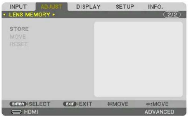
This function serves to store the adjusted values for each input signal when using the LENS SHIFT, ZOOM and FOCUS buttons of the projector. Adjusted values can be applied to the signal you selected. This will eliminate the need to adjust lens shift, focus, and zoom at the time of source selection.
STORE....Stores the current adjusted values in memory for each input signal.
MOVE ...... Applies the adjusted values to the current signal.
RESET......Returns the adjusted values to the last condition.
NOTE:
- Lens memory adjustments will be automatically registered the ENTRY LIST. These lens memory adjustments can be loaded from the ENTRY LIST. (→ page 89)
Note that performing [CUT] or [ALL DELETE] in the ENTRY LIST will delete lens memory adjustments as well as source adjustments. This deletion will not take effect until other adjustments is loaded. - For storing each adjustment of lens shift, zoom and focus as common value for all input signal, store them as reference lens memory.
To store your adjusted values in [LENS MEMORY]:
- Project the connected device signal you want to adjust.
- Adjust the projecting image of position, size and focus by the LENS SHIFT/HOME POSITION, ZOOM +/-, and FOCUS +/- buttons.
- Adjustment can be performed by the remote control. Please refer to "Adjusting the Picture Size and Position" on page 22.
- Slight adjustment by moving the projector position and by the tilt foot is not subject of [LENS MEMORY].
3. Move the cursor on [STORE] and press ENTER.

- Move the cursor on [YES] and press ENTER.
To call up the adjusted values from [LENS MEMORY]:
- From the menu, select [ADJUST] → [LENS MEMORY] → [MOVE] and press the ENTER button.

The confirmation screen will be displayed.
- Press the ◀ button to select and [YES] and press the ENTER button.
During projection, if the adjusted values for an input signal have been saved, the lens will shift. If not, the lens will shift according to the adjusted values stored in the selected [REF. LENS MEMORY] [PROFILE] number.
To automatically apply the adjusted values at the time of source selection:
- From the menu, select [SETUP] → [INSTALLATION(2)] → [REF. LENS MEMORY] → [LOAD BY SIGNAL] and press the ENTER button.

- Press the ▼ button to select and [ON] and press the ENTER button.
This will move the lens automatically to the position at the time of source selection according to the adjusted values.

NOTE:
- The Lens Memory function may not produce a completely aligned image (due to tolerances in the lenses) using the adjusted values stored in the projector. After calling up and applying the adjusted values from the Lens Memory function, finely adjust the lens shift, zoom and focus to produce the best possible image.
⑥ Menu Descriptions & Functions [DISPLAY]
[PIP/PICTURE BY PICTURE]

SUB INPUT
Select the input signal to be displayed in the sub-display.
Please refer to "4-2 Displaying Two Pictures at the Same Time" ( page 70) for details on the operation.
MODE
Select either PIP or PICTURE BY PICTURE when switching to 2-screen display.
PICTURE SWAP
The videos in the main display and sub-display will be switched.
Please refer to "4-2 Displaying Two Pictures at the Same Time" ( page 72) for details.
PIP SETTING
Select the display position, position adjustment and size of the sub-display in the PIP screen.
START POSITION... Selection of the display position of the sub-display when switching to the PIP screen.
HORIZONTAL POSITION
....Adjust the display position of the sub-display in the horizontal direction. The respective corners will serve as reference points.
VERTICAL POSITION
....Adjust the display position of the sub-display in the vertical direction. The respective corners will serve as reference points.
SIZE......Select the display size of the sub-display.
TIP:
The horizontal position and vertical position are the amount of movement from the reference points. For example, when TOP-LEFT is adjusted, the position is displayed with the same amount of movement even if displayed with other starting positions.
The maximum amount of movement is half the resolution of the projector.

BORDER
Select the display boundary of the main display and sub-display of the [PICTURE BY PICTURE] screen.

TIP:
- 6 steps can be selected on this projector.
[GEOMETRIC CORRECTION]

MODE
Set pattern for correcting distortion. If [OFF] is selected, the [GEOMETRIC CORRECTION] becomes ineffective.
KEYSTONE
Correct distortion in horizontal and vertical directions.
HORIZONTAL...... Adjustments when projecting from a diagonal direction to the screen.
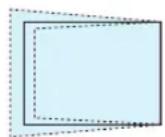
VERTICAL.... Adjustments when projecting from the top or bottom direction to the screen.

TILT ....Adjusts the distortion when performing trapezoidal correction with the screen moved in the vertical direction using the lens shift.
THROW RATIO......Adjusts according to the projection ratio of the optional lens used.
| Model name of lens unit | Adjustment range |
| NP16FL 7-8 | |
| NP17ZL 12-18 | |
| NP18ZL 17-23 | |
| NP19ZL 21-37 | |
| NP20ZL 34-55 | |
| NP21ZL 50-85 | |
| NP31ZL 7-10 | |
| NP39ML 4 |
NOTE:
- When power is supplied to the device, the adjustment value of the [KEYSTONE] used previously is retained even if the gradient of the device is changed.
- As electrical correction is carried out by [KEYSTONE], the brightness may be reduced or the screen quality may deteriorate sometimes.
CORNERSTONE
Display the 4-point correction screen and adjust the trapezoidal distortion of the projection screen.
Please refer to "Correcting Horizontal and Vertical Keystone Distortion [CORNERSTONE]" (→ page 42) for details on the operation.
HORIZONTAL CORNER/VERTICAL CORNER
Distortion correction for corner projection such as wall surfaces.
HORIZONTAL CORNER
...... Performs correction for projection onto a wall lying at an angle to the horizontal direction.

natural_image
Diagram showing two 3D geometric shapes with blue vertical bars inside, connected by an arrow (no text or symbols)* Reverse angle correction is also possible.
VERTICAL CORNER
...... Performs correction for projection onto a wall lying at an angle to the vertical direction.
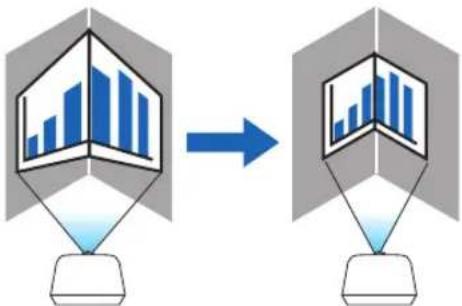
flowchart
graph TD
    A["3D Model"] --> B["Data Collection"]
    B --> C["2D Model"]
    style A fill:#f9f,stroke:#333
    style C fill:#bbf,stroke:#333
* Reverse angle correction is also possible.
NOTE:
- When the maximum adjustment range is exceeded, distortion adjustment is disabled. Set up the projector at an optimal angle as the deterioration in the image quality increases as the distortion adjustment volume gets larger.
- Please note that the image will go out of focus due to the difference in the distance between the upper and lower or left and right sides and the center of the screen for projections cutting across corners. Lenses with short focal points are also not recommended for projections cutting across corners as the image will go out of focus.
Adjustment method
- Align the cursor with the [HORIZONTAL CORNER] or [VERTICAL CORNER] of the [GEOMETRIC CORRECTION] menu and then press the ENTER button.
• The adjustment screen will be displayed.
- Press the ▼▲◀▶ buttons to align the cursor (yellow box) with the target adjustment point and then press the ENTER button.
- The cursor will change into an adjustment point (yellow in color).
- Press the ▼▲◀▶ buttons to adjust the corners or sides of the screen and then press the ENTER button.
- The adjustment point will go back to being a cursor (yellow box).
Explanation of screen transition
- The adjustment points of the four corners (a, c, f and h in the drawing) will move independently.
- The following adjustment points differ at the [HORIZONTAL CORNER] and [VERTICAL CORNER].
HORIZONTAL CORNER: When Point b in the drawing is moved, and the upper side and Point g are moved, the lower side will move in a parallel manner.
VERTICAL CORNER: When Point d in the drawing is moved, and the left side and Point e are moved, the right side will move in a parallel manner.
[Adjustment points of the [HORIZONTAL CORNER] screen and movement points of the projection screen]
Point b will be displaced in a parallel manner at the same time as Points a, b, c

flowchart
graph TD
    A["a"] --> B["b"]
    B --> C["c"]
    D["d"] --> E["e"]
    E --> F["h"]
    G["f"] --> H["g"]
    H --> I["h"]
    J["b"] --> K["c"]
    K --> L["d"]
    M["e"] --> N["h"]
    N --> O["h"]
    P["g"] --> Q["h"]
    Q --> R["h"]
    S["d"] --> T["h"]
    T --> U["h"]
    V["d"] --> W["h"]
    W --> X["h"]
    Y["d"] --> Z["h"]
    Z --> AA["h"]
    AB["a"] --> AC["b"]
    AC --> AD["c"]
    AE["d"] --> AF["e"]
    AF --> AG["h"]
    AH["e"] --> AI["h"]
    AI --> AJ["h"]
Point g will be displaced in a parallel manner at the same time as Points f, g, h
[Adjustment points of the [VERTICAL CORNER] screen and movement points of the projection screen]
Point d will be displaced in a parallel manner at the same time as Points a, d, f

flowchart
graph TD
    A["Rectangular Frame"] --> B["Control Panel"]
    style A fill:#f9f,stroke:#333
    style B fill:#bbf,stroke:#333
Point e will be displaced in a parallel manner at the same time as Points f, g, h
-
Start from Step 2 onwards to adjust the other points.
-
When the adjustment is completed, press the ▼▲◀▶ buttons to align the cursor with the [EXIT] in the adjustment screen and then press the ENTER button.
- Switch to the [GEOMETRIC CORRECTION] menu screen.
WARP
Correct projected image distortion on a specific surface as a column or a sphere.
NOTE:
- When the maximum adjustment range is exceeded, distortion adjustment is disabled. Set up the projector at an optimal angle since the more the adjustment volume gets large, the more image quality gets deterioration.
- Please note that the image will go out of focus due to the difference in the distance between peripheries and the center of the screen for projections cutting across corners as on a column or a sphere. Lenses with short focal points are also not recommended for projections cutting across corners as the image will go out of focus.
Adjustment method
- Align the cursor with the [WARP] of the [GEOMETRIC CORRECTION] menu and the press the ENTER.
- Adjustment screen will be displayed on.
- Press the ▼▲◀▶ buttons to align the cursor (blue box) with the target adjustment point and then press the ENTER.
- The cursor will change into an adjustment point (yellow in color).
- Press the ▼▲◀▶ buttons to adjust the corners or sides of the screen and then press the ENTER.
• The cursor will back to yellow box.
Explanation for correcting distortion
• Eight adjustment points can be moved independently.
- For left and right sides, use ◀/▶ buttons for adjusting the range of distortion, and ▼/▲ buttons for adjusting the distortion peak.
- For top and bottom sides, use ▼/▲ buttons for adjusting the range of distortion, and ◀/▶ buttons for adjusting the distortion peak.
- For corners, use ▼▲◀▶ buttons for moving positions.
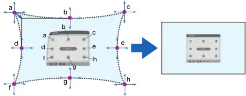
flowchart
graph TD
    A["Central Device"] --> B["Component"]
    B --> C["Control Panel"]
    style A fill:#f9f,stroke:#333
    style B fill:#ccf,stroke:#333
    style C fill:#cfc,stroke:#333
- For adjusting other points, repeat Step2 onwards.
- When the adjustment is completed, move the cursor onto the [EXIT] on the adjustment screen and press the ENTER.
- The screen will be switched to the [GEOMETRIC CORRECTION] menu.
The adjustment completion screen will be displayed on.
- Press ◀ or ▶ button to move the cursor onto [OK] then press [ENTER].
- The adjusted values for WARP are stored and the screen display goes back to the [GEOMETRIC CORRECTION].
PC TOOL
Recall the geometric correction data that is registered in the projector beforehand.
Three types of correction data can be registered.
NOTE:
- As electrical correction is carried out in geometric correction, the brightness may be affected and the picture quality may be degraded.
RESET
Reset the adjustment value that has been selected in GEOMETRIC CORRECTION (return to the initial value). It becomes ineffective when [OFF] is selected for [MODE].
- The adjusted value can be reset also by pressing the 3D REFORM button for two seconds or longer on the remote control.
[EDGE BLENDING]

This adjusts the edges (boundaries) of the projection screen when projecting high resolution videos using a combination of several projectors in the up, down, left and right positions.
MODE
This enables or disables the EDGE BLENDING function.
When MODE is set to ON, the TOP, BOTTOM, LEFT, RIGHT, BLACK LEVEL, and BLEND CURVE settings can be adjusted.
TOP/BOTTOM/LEFT/RIGHT
This selects the EDGE BLENDING locations on the left, right, top and bottom on the screen. The following settings can be adjusted when an item is selected. (→ page 75)
CONTROL .... Enable TOP, BOTTOM, LEFT and RIGHT functions.
MARKER...... Set whether to display marker or not when adjusting the range and display position. When turned on, a magenta marker for adjusting the range adjustment and a green marker for adjusting the display position will be displayed.
RANGE.....Adjust the range (width) of the edge blending.
POSITION ....Adjust the display position of the edge blending.
BLACK LEVEL
Divide the screen into nine parts and keep the black level uniform for each projector.
The nine divisions screens are TOP-LEFT, TOP-CENTER, TOP-RIGHT, CENTER-LEFT, CENTER, CENTER-RIGHT, BOTTOM-LEFT, BOTTOM-CENTER and BOTTOM-RIGHT. (→ page 78)
BLEND CURVE
Set brightness for the EDGE BLENDING section.
[MULTI SCREEN]

WHITE BALANCE
This adjusts the white balance for each projector when projecting using a combination of several projectors. This can be adjusted when [MODE] is set to [ON].
Adjusting the black color of the video.
CONTRAST W, CONTRAST R, CONTRAST G, CONTRAST B
....Adjusting the white color of the video.
PICTURE SETTING
This sets the division condition when projecting using a combination of several projectors. Please refer to "4. Multi-Screen Projection" ( page 66) for details.
| MODE OFF Use | the projector in a standalone state. | |
| ZOOM | This adjusts the position and width of the video area that you wish to divide. The edge blending width will also be automatically set to that width. | |
| TILING This assigns the divided screens to the projectors. The edge blending function will also be set automatically. | ||
| ZOOM | HORIZONTAL ZOOM | This maginifies the video area in the horizontal direction. |
| VERTICAL ZOOM | This maginifies the video area in the vertical direction. | |
| HORIZONTAL POSITION | This shifts the video area in the horizontal direction. | |
| VERTICAL POSITION | This shifts the video area in the vertical direction. | |
| TILING WIDTH | This selects the number of projectors to be arranged horizontally. | |
| HEIGHT This selects the number of projectors to be arranged vertically. | ||
| HORIZONTAL POSITION | This selects the position of the projector starting from the left among those arranged horizontally. | |
| VERTICAL POSITION | This selects the position of the projector starting from the top among those arranged vertically. | |
Conditions for using tiling
- All the projectors need to fulfil the following conditions.
- The panel size must be the same
- The projection screen size must be the same
- The left and right ends or top and bottom ends of the projection screen must be consistent.
- The settings for the left and right edges of the edge blending are the same
- The settings for the top and bottom edges of the edge blending are the same
If the tiling conditions are satisfied, the video screen of the projector at each installation position will be automatically extracted and projected.
If the tiling conditions are not satisfied, adjust the video screen of the projector at each installation position using the zoom function.
- Assign a unique control ID to each projector.
- Set the “Color Setting” and “DeepColor Setting” on your Blu-ray player or computer to “Auto”. Refer to the owner’s manual accompanying your Blu-ray player or computer for more information.
Connect the HDMI output of your Blu-ray player or computer to the first projector. Then connect to the HDMI IN input terminal of the second and subsequent tiled projectors.
Tiling setting example) Number of horizontal units = 2, Number of vertical units = 2
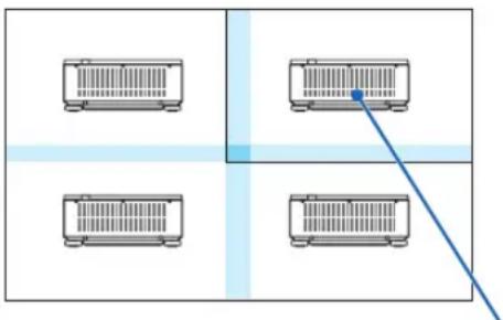
natural_image
Four identical rectangular units arranged in a 2x2 grid with a blue diagonal line connecting them (no text or symbols)Horizontal order = Second unit Vertical order = First unit
⑦ Menu Descriptions & Functions [SETUP]
[MENU(1)]

Selecting Menu Language [LANGUAGE]
You can choose one of 30 languages for on-screen instructions.
NOTE: Your setting will not be affected even when [RESET] is done from the menu.
Selecting Menu Color [COLOR SELECT]
You can choose between two options for menu color: COLOR and MONOCHROME.
Turning On / Off Source Display [INPUT DISPLAY]
This option turns on or off input name display such as HDMI, DisplayPort, BNC, BNC(CV), BNC(Y/C), COMPUTER, HDBaseT to be displayed on the top right of the screen.
Turning messages on and off [MESSAGE DISPLAY]
This option selects whether or not to display projector messages at the bottom of the projected image.
Even when "OFF" is selected, the security lock warning is displayed. The security lock warning turns off when the security lock is canceled.
Turning ON/OFF Control ID [ID DISPLAY]
ID DISPLAY ...... This option turns on or off the ID number which is displayed when the ID SET button on the remote control is pressed. (→ page 127)
[3D CAUTION MESSAGE]
This selects whether to display a caution message or not when switching to a 3D video.
The default condition when shipped from the factory is ON.
OFF .... The 3D caution message screen will not be displayed.
ON .... The 3D caution message screen will be displayed when switching to a 3D video. Press the ENTER button to cancel the message.
- The message will disappear automatically after 60 seconds or when other buttons are pressed. If it disappears automatically, the 3D caution message will be displayed again when switching to a 3D video.
Selecting Menu Display Time [DISPLAY TIME]
This option allows you to select how long the projector waits after the last touch of a button to turn off the menu. The preset choices are [MANUAL], [AUTO 5 SEC], [AUTO 15 SEC], and [AUTO 45 SEC]. The [AUTO 45 SEC] is the factory preset.
[MENU(2)]

[MENU ANGLE]
Select the direction for displaying the menu.
[MENU POSITION]
Shift the menu displaying position.
HORIZONTAL POSITION.....Shift the menu in the horizontal directions.
VERTICAL POSITION ......Shift the menu in the vertical directions.
RESET......Reset the menu displaying position to the default factory setting (the screen center).
TIP
- Once the projector is powered off, the menu displaying position will reset to the default factory setting.
- Input terminal and message displaying position are not influenced by the [MENU POSITION].
[INSTALLATION(1)]

Selecting Projector Orientation [ORIENTATION]
This reorients your image for your type of projection. The options are: desktop front projection, ceiling rear projection, desktop rear projection, and ceiling front projection.
NOTE:
- Please consult the dealer if you require special installation services e.g. when mounting the projector to a ceiling. Never install the projector on your own. This may result in the projector falling down and causing injury to people.
AUTO...... This automatically detects and projects the DESKTOP FRONT and CEILING FRONT.
NOTE:
- The DESKTOP REAR and CEILING REAR will not be detected. Please select manually.

TIP:
- Check whether the automatic DESKTOP FRONT is installed within ± 10 degrees for floor installation and whether the CEILING FRONT is within ± 10 degrees for ceiling installation. Select manually when the projection screen is inverted.
Selecting Aspect Ratio and Position for Screen [SCREEN TYPE]
| Screen type Sets the aspect ratio of the projection screen. | |
| FREE The ratio of the panel is selected. Select this when projecting multi-screen and 17:9 screen (2K). | |
| 4:3 screen For a screen with a 4:3 aspect ratio | |
| 16:9 screen For a screen with a 16:9 aspect ratio | |
| 16:10 screen For a screen with a 16:10 aspect ratio |
NOTE:
- After changing the screen type, check the setting of [ASPECT RATIO] in the menu. (→ page 98)
Using the Wall Color Correction [WALL COLOR]

This function allows for quick adaptive color correction in applications where the screen material is not white.
Selecting Fan Mode [FAN MODE]
Fan Mode is used to set the speed of the internal cooling fan.
MODE ....Select mode for fan speed: AUTO, MIDDLE, and HIGH.
AUTO: Standard mode supplying superior quietness.
MIDDLE: Mode offering well-balanced quietness and parts life.
HIGH: Output the maximum cooling power for prolong life of parts.
- If you use the projector continuously for several days, please make sure to set [HIGH] for [FAN MODE].
NOTE:
- Your setting will not be affected even when [RESET] is done from the menu.
[LIGHT MODE]
Adjusting the energy savings settings and the brightness of each projector in multi-screen projection. For energy savings settings, see page 39 "3-7. Changing LIGHT MODE/Checking Energy-Saving Effect Using LIGHT MODE [LIGHT MODE]".
| LIGHT MODE NOR | NORMAL The light | module luminance (brightness) will become 100% and the screen will turn bright. |
| ECO1 By cont | rolling the brightness and fan speed according to the selected setting, energy can be saved and motion noise and the power consumption can be lowered.Can be selected when [CONSTANT BRIGHTNESS] mode is set to [OFF]. | |
| ECO2 | ||
| CONSTANT BRIGHTNESS | OFF [CONSTANT BRIGHTNESS] mode will be canceled. | |
| ON Maintains | the brightness that is in effect at the time [ON] is selected. Unless [OFF] is selected, the same settings will remain in effect even when the projector is turned off.To re-adjust the brightness, first turn this setting OFF before making further adjustments.NOTE:[CONSTANT BRIGHTNESS] mode is a function used to maintain the brightness at a constant level. Color will not be fixed. | |
| REF. LIGHT ADJUST Brightness | can be adjusted in 1% increments from 20 to 100%.When several projectors are used for multi-screen projection, the brightness can be adjusted individually on each projector.The adjustment is effective when [NORMAL] is selected for the [LIGHT MODE] and [OFF] is selected for the [CONSTANT BRIGHTNESS]. | |
TIP:
- Brightness normally decreases with use, but by selecting [CONSTANT BRIGHTNESS] mode, sensors inside the projector detect brightness and automatically adjust the output, thereby maintaining a constant brightness throughout the life of the light module. However, if output is already at its maximum, brightness will decrease with use.
For this reason, when using multi-screen projection, it is recommended to adjust the brightness to a slightly lower level, then setting the [CONSTANT BRIGHTNESS] mode to [ON].
[REF. WHITE BALANCE]
This feature allows you to adjust the white balance for all signals.
The white and black levels of the signal are adjusted for optimum color reproduction.
CONTRAST R/CONTRAST G/CONTRAST B
...... These adjust the picture's white color.
...... These adjust the picture's black color.
3D GLASSES
Select 3D glasses method.
DLP® Link......Select when using DLP® Link type 3D glasses.
OTHERS...... Select when using a non 3D emitter type glasses. It is required to connect the 3D emitter to the 3D SYNC terminal of this projector. Please refer to page 48 about recommended items of 3D glasses and 3D emitter for this projector.
[INSTALLATION(2)]

[SHUTTER SETTINGS]
Enabling and disabling the lens shutter function. You can also set how long the light will take to fade in and fade out when either the SHUTTER button on the remote control or the SHUTTER/CALIBRATION button on the cabinet is pressed.
| POWER ON SHUTTER | OPEN When the power is turned on, the light source comes on and the pictu projected. | |
| CLOSE | The light source does not come on when the power is turned on.When the SHUTTER button is pressed, the shutter is released and the light source is turned on. | |
| PICTURE MUTE SHUTTER | OPEN | The light source is still on when the picture is turned off for switching the input terminals. |
| CLOSE | The light source turns off when the picture is turned off for switching the input terminals. | |
| FADE IN TIME Set how long the light will take to fade in after the SHUTTER button is pressed.The time can be set from 0 to 10 seconds in increments of 1 second. | ||
| FADE OUT TIME Set how long the light will take to fade out after the SHUTTER button is pressed.The time can be set from 0 to 10 seconds in increments of 1 second. | ||
Using the Reference Lens Memory Function [REF. LENS MEMORY]
This function serves to store the adjusted values common to all input sources when using the LENS SHIFT, ZOOM and FOCUS buttons of the projector or the remote control. The adjusted values stored in memory can be used as a reference to the current.
PROFILE ...... Select a stored [PROFILE] number.
STORE ....Stores the current adjusted values in memory as a reference.
MOVE ...... Applies the adjusted reference values stored in [STORE] to the current signal.
RESET...... Reset selected [PROFILE] number [REF. LENS MEMORY] to the factory default settings.
LOAD BY SIGNAL .. When you switch signals the lens will shift to the lens shift, zoom, and focus values for the selected [PROFILE] number.
If no adjusted values have been saved to [LENS MEMORY], the lens will apply [REF. LENS MEMORY] adjusted values. Alternatively, if no adjusted values have been saved to [REF. LENS MEMORY], the unit will return to factory default settings.
FORCED MUTE ..... To turn off the image during lens shift, select [YES].
NOTE:
- Adjusted values in [REF.LENS MEMORY] will not be returned to default when performing [CURRENT SIGNAL] or [ALL DATA] for [RESET] from the menu.
- To store adjusted values for each input source, use the Lens Memory function. (→ page 60, 103)
- When [PICTURE MUTE SHUTTER] under [SHUTTER SETTINGS] is [ON], [FORCED MUTE] will turn off the light source and stop projection. (→ previous page)
[LENS CALIBRATION]
The adjustment range of the zoom, focus, and shift of the [LENS MEMORY] is calibrated.
Be sure to carry out [LENS CALIBRATION] after replacing the lens.
[LENS POSITION]
Move the lens position.
HOME ...... Set back the lens to the home position.
TYPE...... Select this for using the lens unit NP39ML. The lens position will be adjusted to the appropriate position.
[CONTROL]
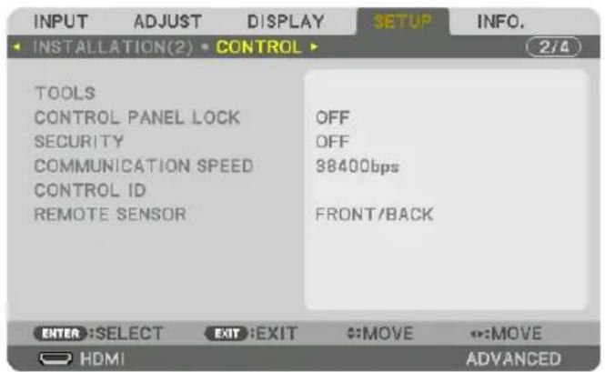
TOOLS

ADMINISTRATOR MODE
This allows you to select MENU MODE, save settings, and set a password for the administrator mode.

| MENU MODE Select either [BASIC] or [ADVANCED] menu. (→ page 82) | — | |
| NOT SAVE SETTING VALUES | Placing a check mark will not save your projector settings. Clear this check box to save your projector settings. | — |
| NEW PASSWORD/CONFIRM PASS-WORD | Assign a password for the administrator mode. Up to 10 alphanumeric characters | |
PROGRAM TIMER

This option turns on/standby the projector and changes video signals, and selects LIGHT mode automatically at a specified time.
NOTE:
- Before using [PROGRAM TIMER], make sure that the [DATE AND TIME] feature is set. (→ page 125)
Make sure that the projector is in the standby condition with the POWER cord connected.
The projector has a built-in clock. The clock will keep working for about two weeks after the main power is turned off. If the main power is not supplied to the projector for two weeks or more, it requires to set [DATE AND TIME SETTINGS] feature again.
Setting a new program timer
- On the PROGRAM TIMER screen, use the ▲ or ▼ button to select [SETTINGS] and press the ENTER button.

The [PROGRAM LIST] screen will be displayed.
- Select a blank program number and press the ENTER button.
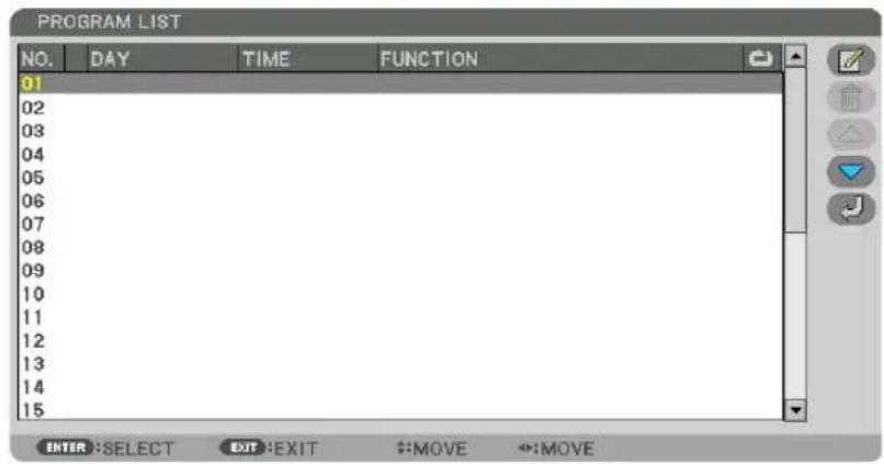
The [EDIT)] screen will be displayed.
- Make settings for each item as required.

ACTIVE .... Place a check mark to enable the program.
DAY...... Select days of the week for the program timer. To execute the program from Monday to Friday, select [MON-FRI]. To execute the program in everyday basis, select [EVERYDAY].
TIME......Set the time to execute the program. Enter time in 24-hour format.
FUNCTION ...... Select a function to be executed. Selecting [POWER] will allow you to turn on or off the projector by setting [ADVANCED SETTINGS]. Selecting [INPUT] will allow you to select a video source by setting [ADVANCED SETTINGS]. Selecting [LIGHT MODE] will allow you to select [LIGHT MODE] by setting [ADVANCED SETTINGS].
ADVANCED SETTINGS
...... Select power on/off, a type of video source, or LIGHT MODE for the selected item in [FUNCTION].
REPEAT...... Place a check mark to repeat the program continuing basis. To use the program this week only, clear the check mark.
4. Select [OK] and press the ENTER button.
This will complete the settings.
You will be returned to the [PROGRAM LIST] screen.
5. Select [J (BACK)] and press the ENTER button.

You will be returned to the [PROGRAM TIMER] screen.
6. Select [EXIT] and press the ENTER button.
You will be returned to the [TOOLS] screen.
NOTE:
- Up to 30 different timer settings can be programmed.
- When [PROGRAM TIMER] is turned on, the [STANDBY MODE] setting is ignored.
- The Program Timer is executed on a set time basis, not in a program basis.
- Once the program not marked with a check in [REPEAT] has been executed, the check mark in the [ACTIVE] check box will be cleared automatically and the program will be disabled.
- When the on-time and the off-time set for the same time, the off-time setting will take preference.
- Two different sources are set for the same time, the larger program number will take preference.
- The on-time setting will not be executed while the cooling fans are running or an error is occurring.
- If the off-time setting is expired under the condition in which the power off is not possible, the off-timer setting will not be executed until the power off becomes possible.
- Programs not marked with a check mark in [ACTIVE] of the [EDIT] screen will not be executed even if the Program Timer is enabled.
- When the projector is turned on by using the program timer and if you want to turn off the projector, set the off-time or do it manually so as not to leave the projector on for a long period of time.
Activating the program timer
- Select [ENABLE] on the [PROGRAM TIMER] screen and press the ENTER button.
The selection screen will be displayed.
- Press the ▼ button to align the cursor with [ON] and then press the ENTER button.
Return to the [PROGRAM TIMER] screen.
NOTE:
- When the effective settings of the [PROGRAM TIMER] have not been set to [ON], the program will not be executed even if the [ACTIVE] items in the program list have been ticked.
- Even when the effective settings of the [PROGRAM TIMER] are set to [ON], the [PROGRAM TIMER] will not work until the [PROGRAM TIMER] screen is closed.
Editing the programmed settings
- On the [PROGRAM LIST] screen, select a program you want to edit and press the ENTER button.
- Change the settings on the [EDIT] screen.
- Select [OK] and press the ENTER button.
The programmed settings will be changed.
You will be returned to the [PROGRAM LIST] screen.
Changing the order of programs
- On the [PROGRAM LIST] screen, select a program whose order you want to change and press the ▶ button.
- Press the ▼ button to select ▲ or ▼.
- Press the ENTER button a few times to select a row to which you wish to move the program.
The order of the programs will be changed.
Deleting the programs
- On the [PROGRAM LIST] screen, select a program number you want to delete and press the ▶ button.
- Press the ▼ button to select [ (DELETE)].
- Press the ENTER button.
The confirmation screen will be displayed.
- Select [YES] and press the ENTER button.
The program will be deleted.
This will complete deleting the program.
DATE AND TIME SETTINGS

You can set the current time, month, date, and year.
NOTE: The projector has a built-in clock. The clock will keep working for about 2 weeks after the main power is turned off. If the main power is off for 2 weeks or more, the built-in clock will cease. If the built-in clock ceases, set the date and time again. The built-in clock will not cease while in the standby mode.
TIME ZONE SETTINGS......Select your time zone.
DATE AND TIME SETTINGS..... Set your current date (MM/DD/YYYY) and time (HH:MM).
INTERNET TIME SERVER: If you place a check mark, the projector's built-in clock will be synchronized with an Internet time server in every 24 hours and at the time of projector's startup.
UPDATE: Synchronizes the projector's built-in clock immediately. The UPDATE button is not available unless the INTERNET TIME SERVER check box is turned on.
SUMMER TIME SETTINGS ...... If you place a check mark, the clock for daylight saving will be enabled.
[MOUSE]
This function cannot be used in this device. It is used for future expansion purposes only.
Disabling the Cabinet Buttons [CONTROL PANEL LOCK]
This option turns on or off the CONTROL PANEL LOCK function.
NOTE:
• How to cancel the [CONTROL PANEL LOCK]
When the [CONTROL PANEL LOCK] is set to [ON], press the SOURCE button on the cabinet for about 10 seconds to cancel the [CONTROL PANEL LOCK].
TIP:
- When the [CONTROL PANEL LOCK] is turned on, a key lock icon [ ] will be displayed at the bottom right of the menu.
- This CONTROL PANEL LOCK does not affect the remote control functions.
Enabling Security [SECURITY]
This feature turns on or off the SECURITY function.
Unless the correct keyword is entered, the projector cannot project an image. (→ page 45)
NOTE: Your setting will not be affected even when [RESET] is done from the menu.
Selecting Communication Speed [COMMUNICATION SPEED]
This feature sets the baud rate of the PC Control port (D-Sub 9P). It supports data rates from 4800 to 115200 bps. The default is 38400 bps. Select the appropriate baud rate for your equipment to be connected (depending on the equipment, a lower baud rate may be recommended for long cable runs).
NOTE:
- Select [38400bps] or less when using the supplied software programs.
- Your selected communication speed will not be affected even when [RESET] is done from the menu.
Setting ID to the Projector [CONTROL ID]
You can operate multiple projectors separately and independently with the single remote control that has the CONTROL ID function. If you assign the same ID to all the projectors, you can conveniently operate all the projectors together using the single remote control. To do so, you have to assign an ID number to each projector.
CONTROL ID NUMBER...... Select a number from 1 to 254 you wish to assign to your projector.
CONTROL ID......Select [OFF] to turn off the CONTROL ID setting and select [ON] to turn on the CONTROL ID setting.
NOTE:
- When [ON] is selected for [CONTROL ID], the projector cannot be operated by using the remote control that does not support the CONTROL ID function. (In this case the buttons on the projector cabinet can be used.)
- Your setting will not be affected even when [RESET] is done from the menu.
- Pressing and holding the ENTER button on the projector cabinet for 10 seconds will display the menu for canceling the Control ID.
Assigning or Changing the Control ID
1. Turn on the projector.
2. Press the ID SET button on the remote control.
The CONTROL ID screen will be displayed.

If the projector can be operated with the current remote control ID, the [ACTIVE] will be displayed. If the projector cannot be operated with the current remote control ID, the [INACTIVE] will be displayed. To operate the inactive projector, assign the control ID used for the projector by using the following procedure (Step 3).
3. Press one of numeric keypad buttons while pressing and holding the ID SET button on the remote control.
Example:
To assign "3", press the "3" button on the remote control.
No ID means that all the projectors can be operated together with a single remote control. To set "No ID", enter "000" or press the CLEAR button.
TIP: The range of IDs is from 1 to 254.
4. Release the ID SET button.
The updated CONTROL ID screen will be displayed.
NOTE:
- The IDs can be cleared in a few days after the batteries are run down or removed.
- If one of buttons of the remote control without batteries is pressed accidentally, current specified ID will be cleared.


Turning On or Off Remote Sensor [REMOTE SENSOR]
This option determines which remote sensor on the projector is enabled in wireless mode. The options are: FRONT/BACK, FRONT, BACK, and HDBaseT.
NOTE:
- The remote control of the projector will not be able to receive signals if the power supply of the HDBaseT supported transmission device connected to the projector on which “HDBaseT” setting has been ON.
TIP:
- If the remote control system does not function when direct sunlight or strong illumination strikes the remote control sensor of the projector, change another option.
[NETWORK SETTINGS]
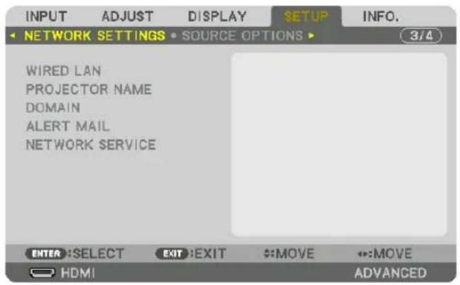
Important:
- Consult with your network administrator about these settings.
- When using a wired LAN connection, connect a LAN cable (Ethernet cable) to the LAN port (RJ-45) of the projector. (→ page 153)
TIP: The network settings you make will not be affected even when [RESET] is done from the menu.
Hints on How to Set Up LAN Connection
To set up the projector for a LAN connection:
Select [WIRED LAN] → [PROFILES] → [PROFILE 1] or [PROFILE 2].
Two settings can be set for wired LAN.
Next turn on or off for [DHCP], [IP ADDRESS], [SUBNET MASK], and [GATEWAY] and select [OK] and press the ENTER button. (→ page 130)
To recall LAN settings stored in the profile number:
Select [PROFILE 1] or [PROFILE 2] for wired LAN, and then select [OK] and press the ENTER button. (→ page 130)
To connect a DHCP server:
Turn on [DHCP] for wired LAN. Select [ON] and press the ENTER button. To specify IP address without using the DHCP server, turn off [DHCP]. (→ page 130)
To receive error messages via e-mail:
Select [ALERT MAIL], and set [SENDER'S ADDRESS], [SMTP SERVER NAME], and [RECIPIENT'S ADDRESS]. Last, select [OK] and press the ENTER button. (→ page 132)
WIRED LAN

| PROFILES • The settings for using the built-in Ethernet/HDBaseT port in the projector can be recorded in the projector memory in two ways. Select [PROFILE 1] or [PROFILE 2] and then do settings for [DHCP] and the other options. After doing this, select [OK] and press the ENTER button. This will store your settings in memory. To recall the settings from memory: After selecting [PROFILE 1] or [PROFILE 2] from the [PROFILES] list. Select [OK] and press the ENTER button. Select [DISABLE] when not connecting to a wired LAN | — | |
| DHCP | Place a check mark to automatically assign an IP address to the projector from your DHCP server. Clear this check box to register the IP address or subnet mask number obtained from your network administrator. | — |
| IP ADDRESS Set your | IP address of the network connected to the projector when [DHCP] is turned off. | Up to 12 numeric characters |
| SUBNET MASK Set your | our subnet mask number of the network connected to the projector when [DHCP] is turned off. | Up to 12 numeric characters |
| GATEWAY | Set the default gateway of the network connected to the projector when [DHCP] is turned off. | Up to 12 numeric characters |
| AUTO DNS Place a check mark to automatically assign the IP address of your DNS server connected to the projector from your DHCP server. Clear this check box to set the IP address of your DNS server connected to the projector. | Up to 12 numeric characters | |
| DNS CONFIGURATION | Set the IP address of your DNS server on the network connected to the projector when [AUTO DNS] is cleared. | Up to 12 numeric characters |
| RECONNECT | Retry to connect the projector to a network. Try this if you have changed [PROFILES]. | — |
PROJECTOR NAME

| PROJECTOR NAME Set a unique projector name. Up to 16 alphanu- | meric characters and symbols |
DOMAIN
Set a host name and domain name of the projector.

| HOST NAME Set a host name of the projector. Up to 15 alphanumeric | characters |
| DOMAIN NAME Set a domain name of the projector. Up to 60 alphanumeric | characters |
ALERT MAIL
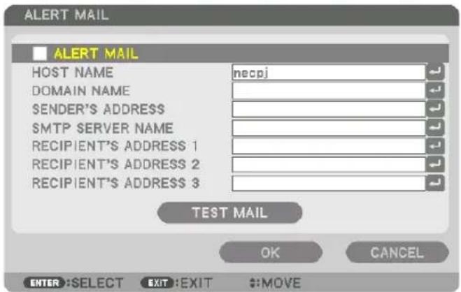
| ALERT MAIL This option will notify your computer of error messages via e-mail when using wireless or wired LAN.Placing a checkmark will turn on the Alert Mail feature.Clearing a checkmark will turn off the Alert Mail feature.Sample of a message to be sent from the projector:Subject: [Projector] Projector InformationTHE COOLING FAN HAS STOPPED.[INFORMATION]PROJECTOR NAME: PX1004UL SeriesLIGHT HOURS USED: 0000[H] | — |
| HOST NAME Type in a host name. Up to 15 alphanumeric | characters |
| DOMAIN NAMEType in a domain name of the network connected to the projector. | Up to 60 alphanumeric characters |
| SENDER'S AD-DRESSSpecify the sender's address. Up to 60 alphanu- | meric characters and symbols |
| SMTP SERVER NAMEType in the SMTP server name to be connected to the projector. | Up to 60 alphanumeric characters |
| RECIPIENT'S AD-DRESS 1, 2, 3Type in your recipient's address. Up to 60 alphanu- | meric characters and symbols |
| TEST MAIL Send a test mail to check if your settings are correct.NOTE:If you entered an incorrect address in a test, you may not receive an Alert mail. Should this happen, check if the Recipient's Address is correctly set.Unless any one of the [SENDER'S ADDRESS], [SMTP SERVER'S NAME] or [RECIPIENT'S ADDRESS 1-3] is selected, [TEST MAIL] is not available.Be sure to highlight [OK] and press the ENTER button before executing [TEST MAIL]. | — |
NETWORK SERVICE

| HTTP SERVER Set a password for your HTTP server. Up to 10 alphanumeric characters | ||
| PJLink | This option allows you to set a password when you PJLink feature.NOTE:Do not forget your password. However, if you forget your password, consult with your dealer.What is PJLink?PJLink is a standardization of protocol used for controlling projectors of different manufacturers. This standard protocol is established by Japan Business Machine and Information System Industries Association (JBMIA) in 2005.The projector supports all the commands of PJLink Class 1.Setting of PJLink will not be affected even when [RESET] is done from the menu. | Use to 32 alphanumeric characters |
| AMX BEACON Turn on | or off for detection from AMX Device Discovery when connecting to the network supported by AMX's NetLinx control system.TIP:When using a device that supports AMX Device Discovery, all AMX NetLinx control system will recognize the device and download the appropriate Device Discovery Module from an AMX server.Placing a checkmark will enable detecting the projector from AMX Device Discovery.Clearing a checkmark will disable detecting the projector from AMX Device Discovery. | — |
| CRESTRON | ROOMVIEW: Turn on or off when controlling the projector from your PC.CRESTRON CONTROL: Turn on or off when controlling projector from your controller.CONTROLLER IP ADDRESS: Enter your IP address of CRESTRON SERVER.IP ID: Enter your IP ID of CRESTRON SERVER. | Up to 12 numeric charactersthe |
| Extron XTP Set for connecting this projector to the Extron XTP transmitter.Placing a checkmark will enable to connect with the XTP transmitter. Clearing a checkmark will disable to connect with the XTP transmitter. | ||
TIP: The CRESTRON settings are required only for use with CRESTRON ROOMVIEW.
For more information, visit http://www.crestron.com
[SOURCE OPTIONS]

Setting Auto Adjust [AUTO ADJUST]
This feature sets the Auto Adjust mode so that the computer signal can be automatically or manually adjusted for noise and stability. You can automatically make adjustment in two ways: [NORMAL] and [FINE].
OFF .... The computer signal will not be automatically adjusted. You can manually optimize the computer signal.
NORMAL...... Default setting. The computer signal will be automatically adjusted. Normally select this option.
FINE...... Select this option if fine adjustment is needed. It takes more time to switch to the source than when [NORMAL]is selected.
TIP:
- The default setting when shipped from the factory is [NORMAL].
- When the AUTO ADJ. button is pressed, the same [FINE] adjustment is carried out.
[COLOR SYSTEM]
This feature allows you to select the TV video signal, which differs from country to country (NTSC, PAL, etc.). This is set to [AUTO] by factory default. Set this if the projector cannot identify the signal automatically.
Selecting Default Source [DEFAULT INPUT SELECT]
You can set the projector to default to any one of its inputs each time the projector is turned on.
LAST....Set the projector to default to the previous or last active input each time the projector is turned on.
AUTO ....Search for an active source in order of HDMI → DisplayPort → BNC → BNC(CV) → BNC(Y/C) → COMPUTER → HDBaseT → SLOT and displays the first found source.
HDMI ...... Display the digital source from the HDMI IN terminal every time the projector is turned on.
DisplayPort...... Display the digital source from the DisplayPort IN terminal every time the projector is turned on.
BNC ...... Project the input signal from the BNC IN terminal
BNC(CV).... Project the input signal from the BNC(CV) input terminal.
BNC(Y/C) ...... Project the input signal from the BNC(Y/C) input terminal.
COMPUTER ...... Display the computer signal from the COMPUTER IN terminal every time the projector is turned on.
HDBaseT......Project the HDBaseT or WIRED LAN signal.
SLOT...... Project the picture via the optional board (sold separately) inserted into the SLOT.
Setting Closed Caption [CLOSED CAPTION]
This option sets several closed caption modes that allow text to be superimposed on the projected image of Video or S-Video.
The subtitles and text will be displayed a short while after the on-screen menu disappears.
OFF ...... This exits the closed caption mode.
CAPTION 1-4 ...... Text is superimposed.
TEXT 1-4......Text is displayed.
Selecting a Color or Logo for Background [BACKGROUND]
Use this feature to display a blue/black screen or logo when no signal is available. The default background is [BLUE].
NOTE:
- Even when the background logo is selected, if two pictures are displayed in [PIP/PICTURE BY PICTURE] mode, the blue background is displayed without the logo when there is no signal.
[POWER OPTIONS]

Selecting Power-saving in [STANDBY MODE]
Setting the power consumption in the standby mode.
NORMAL...... In the standby mode, the power consumption of the projector is 0.20 W (110-130 V) / 0.30 W (200-240 V).
In the standby mode, the POWER indicator lights up in red while the STATUS indicator will go off.
- When set to [NORMAL], the following terminals and functions will be disabled. HDMI OUT terminals, Ethernet/HDBaseT port, LAN function, mail notification function
NETWORK STANDBY
...... Compared to [NORMAL], the power consumption in the standby mode is higher but power can be supplied to the projector using a wired LAN.
In the standby mode, the power indicator will light up in orange while the status indicator will be turned off.
Important:
- When [NETWORK STANDBY] is selected, [AUTO POWER OFF] will turn grey in color and be disabled and [0:15] will be selected automatically.
- In the following conditions, the [STANDBY MODE] setting will be disabled and the projector will go into the sleep mode. In the sleep mode, the fans in the projector rotate for the purpose of interior parts protection.
* Sleep mode refers to the mode whereby the functional restrictions due to the [STANDBY MODE] setting are removed.
- When [ON] is selected under [NETWORK SERVICE] → [AMX BEACON]
- When [ENABLE] is selected under [NETWORK SERVICE] → [CRESTRON] → [CRESTRON CONTROL].
- When [ON] is selected under [NETWORK SERVICE] [Extron XTP].
- When [HDBaseT] is selected under [CONTROL] [REMOTE SENSOR]
- When a signal is being received from a HDBaseT transmission device
- When [NORMAL] is selected, the [AUTO POWER ON SELECT] display turns grey in color and is disabled, and [OFF] is automatically selected.
NOTE:
- When connecting to a HDBaseT transmission device sold commercially, if the transmission device is set to transmit remote control signals, the power consumption of the projector in the standby mode will increase.
TIP:
- Your setting will not be affected even when [RESET] is done from the menu.
- The power consumption in the standby mode will not be included in calculating CO_2 emission reduction.
Enabling Direct Power On [DIRECT POWER ON]
Turns the projector on automatically when the power cord is inserted into an active power outlet. This eliminates the need to always use the POWER button on the remote control or projector cabinet.
Turning On the Projector By Applying Computer Signal [AUTO POWER ON SELECT]
If set to [NETWORK STANDBY], the projector automatically detects the synchronizing signal input from the following selected terminals and projects the picture accordingly: Computer, HDMI, DisplayPort, HDBaseT, and SLOT.
OFF ...... AUTO POWER ON SELECT function will be switch off.
HDMI, DisplayPort, COMPUTER, HDBaseT, SLOT
...... When a computer signal of a selected input terminal is detected, the power supply of the projector will be turned on automatically and the computer screen will be projected.
NOTE:
- If you want to activate the AUTO POWER ON SELECT function after powering OFF the projector, interrupt the signal from the input terminals or disconnect the computer cable from the projector and wait for at least 3 seconds before inputting the signal from the selected terminal. When the projector is turned off and enters NETWORK STANDBY mode, but signals from the computer continue to be sent the projector, the projector maintains NETWORK STANDBY mode and will not turn ON automatically. In addition, if signals from HDMI, DisplayPort or HDBaseT continue to be sent to the projector, depending on the settings of connected external devices, the projector may turn ON automatically even if it is powered off and NETWORK STANDBY mode is in effect.
- This function does not work when component signals come into COMPUTER IN terminal or when computer signals are Sync on Green or Composite Sync.
Enabling Power Management [AUTO POWER OFF]
When this option is selected you can enable the projector to automatically turn off (at the selected time: 0:05, 0:10, 0:15, 0:20, 0:30, 1:00) if there is no signal received by any input or if no operation is performed.
NOTE:
- The power will not go off automatically when a signal from the Ethernet/HDBaseT port is being projected.
- [AUTO POWER OFF] appears in grey when the [STANDBY MODE] is set to [NETWORK STANDBY] and [0:15] will be set automatically.
Using Off Timer [OFF TIMER]
- Select your desired time between 30 minutes and 16 hours: OFF, 0:30, 1:00, 2:00, 4:00, 8:00, 12:00, 16:00.
- Press the ENTER button on the remote control.
- The remaining time starts counting down.
- The projector will turn off after the countdown is complete.
NOTE:
- To cancel the preset time, set [OFF] for the preset time or turn off the power.
- When the remaining time reaches 3 minutes before the projector is turned off, the [THE PROJECTOR WILL TURN OFF WITHIN 3 MINUTES] message will be displayed on the bottom of the screen.
Setting for the Optional Board [SLOT POWER]
When using the optional board installed in the slot, set the following options.
PROJECTOR ON ....This feature will turn on or off the power to the optional board.
OFF: Forcibly turn off the power to the optional board installed in the slot.
ON (Default): Turn on the power to the optional board installed in the slot.
PROJECTOR STANDBY......This feature will automatically enable or disable the optional board installed in the slot when the projector is in standby.
DISABLE: Select this option to disable the optional board in the projector standby.
ENABLE (Default): Select this option to enable the optional board in the projector standby.
Returning to Factory Default [RESET]
The RESET feature allows you to change adjustments and settings to the factory preset for a (all) source (s) except the following:
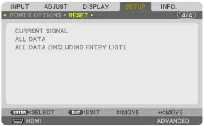
[CURRENT SIGNAL]
Resets the adjustments for the current signal to the factory preset levels.
The items that can be reset are: [PRESET], [CONTRAST], [BRIGHTNESS], [COLOR], [HUE], [SHARPNESS], [ASPECT RATIO], [HORIZONTAL], [VERTICAL], [CLOCK], [PHASE], and [OVERSCAN].
[ALL DATA]
Reset all the adjustments and settings for all the signals to the factory preset.
All items can be reset EXCEPT [LANGUAGE], [BACKGROUND], [EDGE BLENDING], [MULTI SCREEN], [SCREEN TYPE], [GEOMETRIC CORRECTION], [REF. WHITE BALANCE], [CONTROL PANEL LOCK], [SECURITY], [COMMUNICATION SPEED], [DATE AND TIME SETTINGS], [CONTROL ID], [STANDBY MODE], [FAN MODE], [LIGHT HOURS USED], [TOTAL CARBON SAVINGS], and [WIRED LAN].
[ALL DATA (INCLUDING ENTRY LIST)]
Reset all the adjustments and settings for all the signals to the factory preset except [LANGUAGE], [BACKGROUND], [EDGE BLENDING], [MULTI SCREEN], [SCREEN TYPE], [GEOMETRIC CORRECTION], [REF. WHITE BALANCE], [CONTROL PANEL LOCK], [SECURITY], [COMMUNICATION SPEED], [DATE AND TIME SETTINGS], [CONTROL ID], [STANDBY MODE], [FAN MODE], [LIGHT HOURS USED], [TOTAL CARBON SAVINGS], and [WIRED LAN]. Also deletes all the signals in the [ENTRY LIST] and returns to the factory preset.
NOTE: Locked signals in Entry List cannot be reset.
⑧ Menu Descriptions & Functions [INFO.]
Displays the status of the current signal and light module usage. This item has nine pages. The information included is as follows:
TIP: Pressing the HELP button on the remote control will show the [INFO.] menu items.
[USAGE TIME]
![INPUT ADJUST DISPLAY SETUP INFO. • USAGE TIME • SOURCE(1) • SOURCE(2) ▶ 1/3 LIGHT HOURS USED 00000 [H] TOTAL CARBON SAVINGS 0.000[kg-CO2] EXIT:EXIT ↔:MOVE ↔:MOVE HDMI ADVANCED](/content/2026/05/957502/images/7e7e413e2ef58156cb89a179ac5f00e43e8a3f5b27d37bf226275549e2811b04.jpg)
[LIGHT HOURS USED] (H)
[TOTAL CARBON SAVINGS] (kg-CO2)
• [TOTAL CARBON SAVINGS]
This displays the estimated carbon saving information in kg. The carbon footprint factor in the carbon saving calculation is based on the OECD (2008 Edition). ( page 41)
[SOURCE(1)]
![INPUT ADJUST DISPLAY SETUP INFO. USAGE TIME SOURCE(1) SOURCE(2) 1/3 INPUT TERMINAL HDMI RESOLUTION 1024x768 HORIZONTAL FREQUENCY 48.58[kHz] VERTICAL FREQUENCY 82.13[Hz] SYNC TYPE SEPARATE SYNC SYNC POLARITY H:( - ) V:( - ) SCAN TYPE NON-INTERLACE SOURCE NAME 1024x768 ENTRY NO. 1 EXIT:EXIT MOV E:MOVE HDMI ADVANCED](/content/2026/05/957502/images/ccc690eca59f870cd39b238ae645e4204fa125fdf1fe12a8d3e841efe7d5d682.jpg)
INPUT TERMINAL RESOLUTION
HORIZONTAL FREQUENCY VERTICAL FREQUENCY
SYNC TYPE SYNC POLARITY
SCAN TYPE SOURCE NAME
ENTRY NO.
[SOURCE(2)]
![INPUT ADJUST DISPLAY SETUP INFO. USAGE TIME SOURCE(1) SOURCE(2) SIGNAL TYPE RGB VIDEO TYPE NTSC BIT DEPTH 6[bits] VIDEO LEVEL FULL LINK RATE 2.7[Gbps] LINK LANE 1[lane] 3D FORMAT FRAME PACKING EXIT EXIT MOVE ↔:MOVE HDMI ADVANCED](/content/2026/05/957502/images/2ffc8246545798c56abd36ab96055bfb7eea6479567c5143b90da66edae92ab8.jpg)
SIGNAL TYPE VIDEO TYPE
SCAN TYPE SOURCE NAME
ENTRY NO.
[SOURCE(4)]
![INPUT ADJUST DISPLAY SETUP INFO. SOURCE(3) SOURCE(4) WIRED LAN VERSION(1) 2/3 SIGNAL TYPE RGB VIDEO TYPE NTSC BIT DEPTH 6[bits] VIDEO LEVEL FULL LINK RATE 2.7[Gbps] LINK LANE 1[lane] 3D FORMAT FRAME PACKING EXIT:EXIT MOV E:MOVE HDMI ADVANCED](/content/2026/05/957502/images/0d083be41e08efdf73cda86f5c7ca2a6701fe645d775b097ba0935099980e473.jpg)
SIGNAL TYPE VIDEO TYPE
IP ADDRESS SUBNET MASK
GATEWAY MAC ADDRESS
[VERSION(1)]
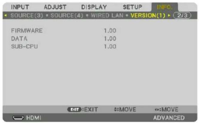
FIRMWARE DATA
SUB-CPU
[OTHERS]

DATE TIME PROJECTOR NAME
MODEL NO. SERIAL NUMBER
CONTROL ID (when [CONTROL ID] is set)
[HDBaseT]

6. Connecting to Other Equipment
① Mounting a lens (sold separately)
This projector can be used with 8 kinds of optional lenses (sold separately). The descriptions here are for the NP18ZL (standard zoom) lens. Mount other lenses in the same manner. See page 172 for lens options.
Important:
- For using the following option lenses, be sure to carry out [LENS CALIBRATION] after replacing the lens. (→ page 18, 120) NP16FL, NP17ZL, NP18ZL, NP19ZL, NP20ZL, NP21ZL, NP31ZL

WARNING:
(1) Turn off the power and wait for the cooling fan to stop, (2) turn off the main power switch, (3) disconnect the power cord and wait for the unit to cool before mounting or removing the lens. Failure to do so can result in eye injury, electric shock, or burn injuries.
NOTE:
• The projector and lenses are made of precision parts. Do not subject them to shock or excessive forces.
- Remove the separately sold lens when moving the projector. If not, the lens could be subject to shock while the projector is being moved, damaging the lens and the lens shift mechanism.
- When dismounting the lens from the projector, return the lens position to the home position before turning off the power. Failure to do so may prevent the lens from being mounted or dismounted because of narrow space between the projector and the lens.
- Never touch the lens surface while the projector is operating.
- Be very careful not to let dirt, grease, etc., on the lens surface and not to scratch the lens surface.
- Perform these operations on a flat surface over a piece of cloth, etc., to prevent the lens from getting scratched.
- When leaving the lens off the projector for long periods of time, mount the dust cap on the projector to prevent dust or dirt from getting inside. If the lens remains detached from the projector for long periods of time, dust may collect within the optical unit and damage the lens, causing deterioration of projected image.
- Lenses other than specified in this manual cannot be mounted on this projector.
Mounting the lens
1. Remove the dust cap from the projector.
Push the tongue at the top left outward and pull the knob at the center of the cap.
2. Remove the lens cap on the back of the lens.
• The lens NP18ZL is used as an example.
NOTE:
- Make sure to remove the lens cap at the unit back side. If the lens unit with the lens cap remaining on is installed on the projector, it may cause of malfunction.
3. Hold the lens unit aligning the labelled arrow on the unit coming top and insert the unit to the projector.
Insert the lens slowly all the way in, keeping the positioning slit at the same angle.

4. Turn the lens unit rightward until click is heard.
The lens is now fastened onto the projector.
TIP: Mounting the lens theft prevention screw
Fasten the lens theft prevention screw included with the projector to the bottom of the projector so that the lens cannot be removed easily.
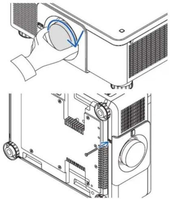
natural_image
Technical illustration of a projector module with a hand operating the blade (no text or symbols present)Removing the lens
Before removing the lens:
- Turn on the projector and display an image. (→ page 17)
- Press and hold the SHUTTER/HOME POSITION button over 2 seconds.
The lens position will be moved to the home position. - Turn off the main power switch, and then unplug the power cord.
- Wait until the projector cabinet is cool enough to handle.
1. While pressing the LENS release button on the projector's front panel fully in, turn the lens counterclockwise.
The lens comes off.
NOTE: If the lens cannot be removed when the LENS release button is pressed, check whether the lens theft prevention screw is mounted.
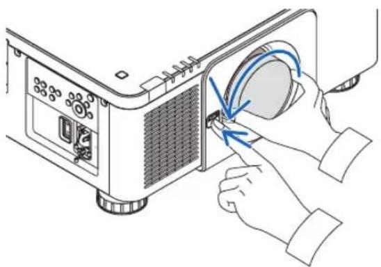
natural_image
Illustration of hands operating a projector with a close-up of the screen (no text or symbols visible)2. After slowly pulling the lens off the projector, release the LENS release button.
- After removing the lens, mount the lens caps (front and back) included with the lens before storing the lens.
- If no lens is going to be mounted on the projector, mount the dust cap included with the projector.

natural_image
Illustration of hands operating a projector with a blue arrow indicating the action (no text or symbols present)② Making Connections
A computer cable, BNC cable (5-core type), HDMI cable, or a DisplayPort cable can be used to connect to a computer. The connection cable is not enclosed with the projector. Please get ready a suitable cable for the connection.
Analog RGB signal connection
- Connect the computer cable to the display output terminal (mini D-sub 15 pin) on the computer and the COMPUTER IN terminal on the projector. Please use a computer cable attached with a ferrite core.
- When connecting the display output terminal (mini D-sub 15 pin) on the computer to the BNC IN terminal, use a conversion cable to convert the BNC cable (5 core) to a mini D-sub 15 pin cable.
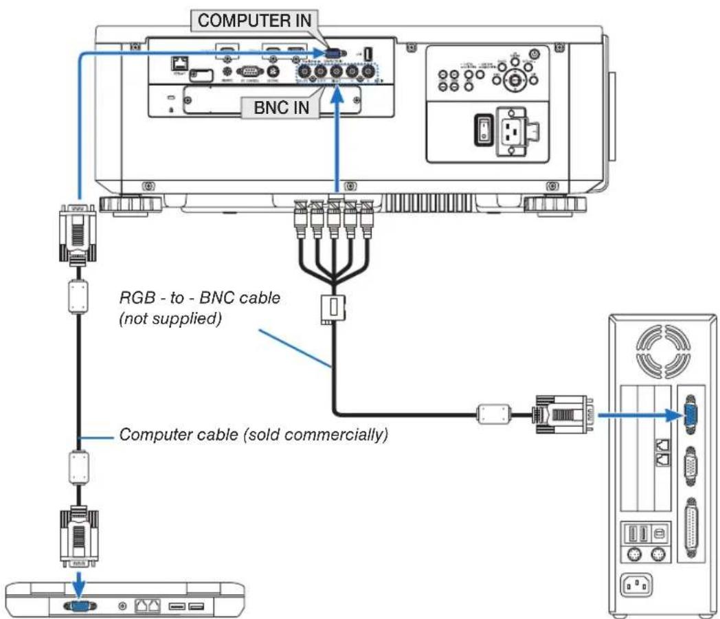
NOTE: Please check the operating manual of the computer as the name, position and direction of the terminal may differ depending on the computer.
- Select the source name for its appropriate input terminal after turning on the projector.
| Input terminal | SOURCE button on the projector cabinet | Button on the remote control |
| COMPUTER IN | COMPUTER 1 | |
| BNC IN BNC COMPUTER 2 x5 | ||
Digital RGB signal connection
- Connect a commercially available HDMI cable between the computer's HDMI output terminal and the projector's HDMI IN terminal.
- Connect a commercially available DisplayPort cable between the computer's DisplayPort output terminal and the projector's DisplayPort IN terminal.

- Select the source name for its appropriate input terminal after turning on the projector.
| Input terminal | SOURCE button on the projector cabinet | Button on the remote control |
| HDMI IN HDMI | HDMI | |
| DisplayPort IN | DisplayPort | DisplayPort |
Cautions when connecting an HDMI cable
- Use a certified High Speed HDMI ^ Cable or High Speed HDMI ^ Cable with Ethernet.
Cautions when connecting a DisplayPort cable
- Use a certified DisplayPort cable.

- Depending on the computer, some time may be required until the image is displayed.
- Some DisplayPort cables (commercially available) have locks.
- To disconnect the cable, press the button on the top of the cable's terminal, then pull the cable out.
- Power can be supplied to the connecting device from the DisplayPort IN terminal (maximum of 1.65 W). However, power will not be supplied to the computer.
- When signals from a device that uses a signal converter adapter are connected to the DisplayPort IN terminal, in some cases the image may not be displayed.
- When the HDMI output of a computer is connected to the DisplayPort IN terminal, use a converter (commercially available).
Cautions when using a DVI signal
- When the computer has a DVI output terminal, use a commercially available converter cable to connect the computer to the projector's HDMI IN terminal (only digital video signals can be input).

NOTE: When Viewing a DVI Digital Signal
- Turn off the power of the computer and projector before connecting devices.
- When a video deck is connected via a scan converter, etc., the display may not be correct during fast-forwarding and rewinding.
- Use a DVI-to-HDMI cable compliant with DDWG (Digital Display Working Group) DVI (Digital Visual Interface) revision 1.0 standard. The cable should be within 197"/5 m long.
- Turn off the projector and the PC before connecting the DVI-to-HDMI cable.
- To project a DVI digital signal: Connect the cables, turn the projector on, then select the HDMI. Finally, turn on your PC. Failure to do so may not activate the digital output of the graphics card resulting in no picture being displayed. Should this happen, restart your PC.
- Some graphics cards have both analog RGB (15-pin D-Sub) and DVI (or DFP) outputs. Use of the 15-pin D-Sub terminal may result in no picture being displayed from the digital output of the graphics card.
- Do not disconnect the DVI-to-HDMI cable while the projector is running. If the signal cable has been disconnected and then reconnected, an image may not be correctly displayed. Should this happen, restart your PC.
- The COMPUTER IN terminals support Windows Plug and Play. The BNC IN terminal does not support Windows Plug and Play.
- A Mac signal adapter (commercially available) may be required to connect a Mac computer.
To connect a Mac computer equipped with a Mini DisplayPort to the projector, use a commercially available Mini DisplayPort → DisplayPort converter cable.
Connecting an External Monitor
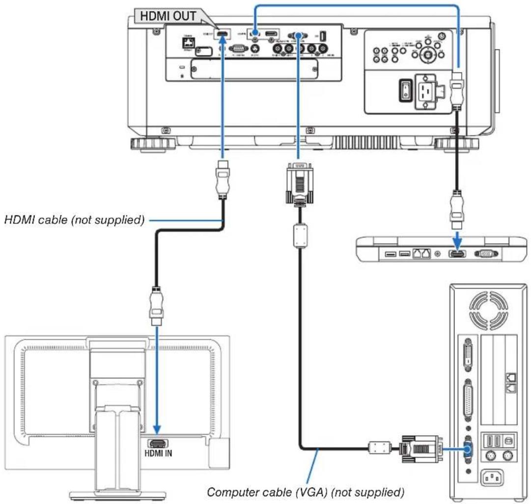
You can connect a separate, external monitor to your projector to simultaneously view on a monitor the computer analog image you're projecting.
- Signals that can be output from the HDMI-OUT terminal are HDMI, DiplayPort, HDBaseT, and SLOT.
- Please refer to Page 70 when displaying the PIP/PBP screen.
NOTE:
- When outputting HDMI signals, turn on the power of the video device on the output side and keep it connected before inputting video signals into this device. The HDMI OUT terminals of the projector are equipped with repeater functions. When a device is connected to the HDMI OUT terminal, the resolution of the output signal is limited by the resolution supported by the connected device.
- In the case of the HDMI OUT terminal of the projector, the theoretical number of units that can be connected in a series is seven. The maximum number of units that can be connected may be reduced by the external environment and quality of the signal and cable, etc. The number of units that can be connected may differ depending on the HDCP version, restriction on the number of HDCP repeaters in the source device and the quality of the cable. The overall system needs to be checked in advance when building a system.
- When the [STANDBY MODE] is set to [NORMAL], video will not be output if the projector goes into the standby mode. Set the mode to [NETWORK STANDBY], turn on the power of the transmission device and keep it in a connected state.
- HDMI repeater function will not be functioned if switching terminals and putting in/pulling out the HDMI cable is performed on the 2nd projector and after.
Connecting Your Blu-ray Player or Other AV Equipment
Component video signal/S-video signal connection

- Select the source name for its appropriate input terminal after turning on the projector.
| Input terminal | SOURCE button on the projector cabinet | Button on the remote control |
| BNC(CV) | ||
| BNC(Y/C) |
Connecting Component Input

- Select the source name for its appropriate input terminal after turning on the projector.
| Input terminal | SOURCE button on the projector cabinet | Button on the remote control |
| COMPUTER IN | COMPUTER 1 | |
| BNC IN BNC COMPUTER 2 ×5 | ||
NOTE:
- When the signal format is set to [AUTO] (default factory setting when shipped), the computer signal and component signal are automatically distinguished and switched. If the signals cannot be distinguished, select [COMPONENT] under [ADJUST] → [VIDEO] → [SIGNAL TYPE] in the on-screen menu of the projector.
- To connect to a video device with a D terminal, use the sold separately D terminal converter adapter (model ADP-DT1E).
Connecting HDMI Input
You can connect the HDMI output of your Blu-ray player, hard disk player, or notebook type PC to the HDMI IN terminal of your projector.

| Input terminal | SOURCE button on the projector cabinet | Button on the remote control |
| HDMI IN HDMI | HDMI |
TIP: For users of audio video equipment with an HDMI terminal:
Select "Enhanced" rather than "Normal" if HDMI output is switchable between "Enhanced" and "Normal".
This will provide improved image contrast and more detailed dark areas.
For more information on settings, refer to the instruction manual of the audio video equipment to be connected.
- When connecting the HDMI IN terminal of the projector to the Blu-ray player, the projector's video level can be made settings in accordance with the Blu-ray player's video level. In the menu select [ADJUST] → [VIDEO] → [VIDEO LEVEL] and make necessary settings.
Connecting to a Wired LAN
The projector comes standard with a Ethernet/HDBaseT port (RJ-45) which provides a LAN connection using a LAN cable.
To use a LAN connection, you are required to set the LAN on the projector menu. Select [SETUP] → [NETWORK SETTINGS] → [WIRED LAN]. (→ page 129).
Example of LAN connection
Example of wired LAN connection
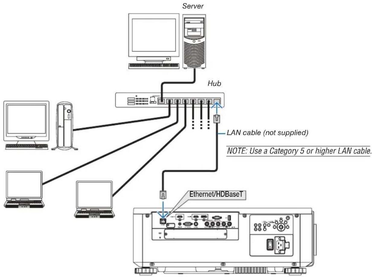
flowchart
graph TD
    Server["Server"] --> Hub["Hub"]
    Hub -->|LAN cable (not supplied)| Server1["Server"]
    Hub -->|LAN cable (not supplied)| Server2["Server"]
    Hub -->|LAN cable (not supplied)| Server3["Server"]
    Hub -->|LAN cable (not supplied)| Server4["Server"]
    Hub -->|LAN cable (not supplied)| EthernetHDBaseT["Ethernet/HDBaseT"]
    Server1 --> EthernetHDBaseT
    Server2 --> EthernetHDBaseT
    Server3 --> EthernetHDBaseT
    Server4 --> EthernetHDBaseT
    Note["NOTE: Use a Category 5 or higher LAN cable."]
Connecting to an HDBaseT transmission device (sold commercially)
HDBaseT is a connection standard for home appliances that is established by the HDBaseT Alliance.
Use a LAN cable sold commercially to connect the Ethernet / HDBaseT port of the projector (RJ-45) to a HDBaseT transmission device sold commercially.
The Ethernet/HDBaseT port of the projector supports HDMI signals (HDCP) from transmission devices, control signals from external devices (serial, LAN) and remote control signals (IR commands).
Connection example

flowchart
graph TD
    A["Computer (for control use)"] --> B["Remote control"]
    B --> C["Example of a transmission device"]
    C --> D["HDMI output video device"]
    D --> E["Computer (for output use)"]
    C --> F["Wind-Remote LAN RS-282C AUDIO IN COMPUTER IN HDMI IN"]
    C --> G["Ethernet/HDBaseT"]
NOTE:
- Please use a shielded twisted pair (STP) cable of Category 5e or higher for the LAN cable (sold commercially).
• The maximum transmission distance over the LAN cable is 100 m. (the maximum distance is 70 m for a 4K signal) - Please do not use other transmission equipment between the projector and transmission equipment. The picture quality may be deteriorated as a result.
- This projector is not guaranteed to work with all HDBaseT transmission devices sold commercially.
Portrait projection (vertical orientation)
This projector can be installed vertically to display computer images in portrait orientation.
The menu displaying position can be shifted by selecting the [SETUP] → [MENU(2)] → [MENU ANGLE].

natural_image
Illustration of a rocket on a base with an attached box, showing its launch from a viewing screen (no text or symbols present)
Precautions during installation
- Please do not install the projector in a vertical orientation on top of the floor or table on its own. If not, the projector may fall over, resulting in injury, damage or malfunction.
- A stand for supporting the projector needs to be made for this purpose to keep intake air flow securely and preventive measure of falling over. The stand must be designed such that the center of gravity of the projector is located well within the legs of the stand. If not, the projector may fall over and result in injury, damage and malfunction.
- If the projector is installed on which the intake vent facing down, optical part life may be shorten.
Design and manufacturing conditions for the stand
Please hire an installation service provider (for a fee) for the design and manufacture of a customized stand to be used for portrait projection. Please ensure that the design complies with the following conditions:
- There are 3 ventilation holes at the bottom of the projector. These holes should remain unobstructed.
- Use the 6 screw holes at the back of the projector to secure it to the stand.
Screw hole center dimension: 300 × 300 (pitch = 150) mm
Screw hole dimension on the projector: M4 with the maximum depth 16 mm
4 of the legs can be unscrewed for removal.
• Horizontal adjustment mechanism (for example, bolts and nuts in 4 places)
- Please design the stand so that it does not easily topple over.
Reference drawings
* The drawing showing the dimensional requirements is not an actual stand design drawing.
(Unit: mm)
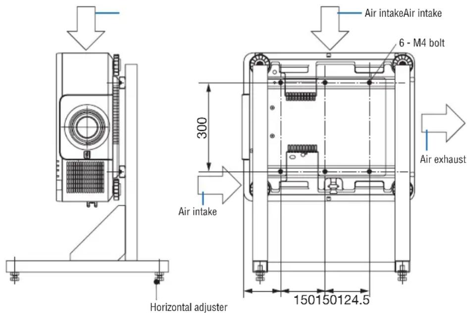
[Side View][Front View]
Stacking projectors
The projected image brightness can be doubled by gravity stacking up to two projectors without external support. This is called “Stacking Projection”.
2 projectors can be stacked on top of each other for "Stacking" setup.


CAUTION:
- A minimum of two persons are required to carry the projector. Otherwise the projector may tumble or drop, causing personal injury.
- Grip the handles for moving the projector.
NOTE:
- Projectors with different model numbers cannot be gravity stacked.
Optional lenses with the same model numbers must be used for stacking projection. - For stacking projectors, attach the supplied four stacking holders to the top of the lower projector. (→ next page)
- It does not support overlay accuracy by stacked projectors. Precise images as small texts and detailed graphics can not be clearly read or seen.
- Use a commercially available distribution amplifier to both the primary (upper) and the secondary (lower) projectors to distribute signal to two outputs of the two projectors.
- Notes for stacking
- Ask your service person for setting up and adjusting projectors.
- Set up the projectors in a place or structure in a way with sufficient strength to support the combined weight of the two projectors. The single projector with a lens weighs up to approximately 32 kg/70 lbs.
- To prevent the projectors from falling, fasten them in a way to withstand earthquakes.
- Double stacking will cause room temperature to increase. Ventilate the room well.
- Do not attempt to stack projectors on the ceiling. Gravity stacking cannot be done on the ceiling.
- Warm up the projectors for one hour before the desired projection is obtained.
- Make sure that the position of the upper projector does not exceed its specifications. When setting up the two projectors, adjustable height range for the tilt foot on the upper projector is added to the total adjustable range.
- Set up the projectors so that the projected image shows as little geometric distortions as possible. The lens is different in geometric distortion between wide(+) and tele (-) for zoom.
- Adjust the horizontal lens shift to the lens center.
Attaching Stacking Holders
Attach three stacking holders to three locations on the top of the lower projector.
Preparation:
Tools required are Phillips screwdriver (plus-head) and four stacking holders packaged with the projector. Loosen the tilt foot (four locations) of the projector.
1. Remove rubber caps and screws at four locations.

natural_image
Isometric line drawing of a rectangular electronic device with mounting holes and ventilation slots (no text or symbols)(1) Use your tweezers or nail to pinch and pull up the rubber cap.
(2) Remove the screw from a square hole.
(1) (2)


2. Attach the three stacking holders at four locations.
(1) Place a stacking holder in a square hole.
(2) Use the screw removed at Step 1 to fix the stacking holder in the square hole.
(3) Put the rubber cap removed at Step 1 back into the square hole.
- Snap the tabs on both of the rubber cap into the slits on both sides in the square hole.
(1) (2) (3)


natural_image
Diagram of a screwdriver using a rotating tool to lift a square component (no text or symbols)
3. Put another projector on the first projector.
Put each tilt foot of the upper projector on the stacking holders (four locations).
• Each tilt foot has a rubber. Place each tilt foot rubber on stacking holders (four locations).
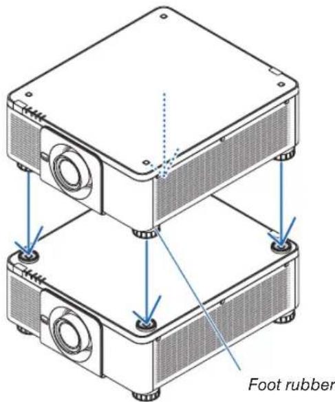
TIP:
• To remove the stacking holders, perform the above steps in reverse order.
7. Maintenance
① Cleaning the Lens
• Turn off the projector before cleaning.
- Use a blower or lens paper to clean the lens, and be careful not to scratch or mar the lens.

WARNING
- Please do not use a spray containing flammable gas to remove dust attached to the lens, etc. Doing so may result in fires.
- Do not look into the lens while the projector is on. Serious damage to your eyes could result.

natural_image
Line drawing of a hand inserting a circular component into a rectangular device (no text or symbols)② Cleaning the Cabinet
Turn off the projector, and unplug the projector before cleaning.
• Use a dry soft cloth to wipe dust off the cabinet.
If heavily soiled, use a mild detergent.
- Never use strong detergents or solvents such as alcohol or thinner.
- When cleaning the ventilation slits or the speaker using a vacuum cleaner, do not force the brush of the vacuum cleaner into the slits of the cabinet.
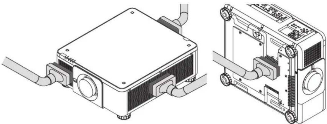
natural_image
Technical line drawing of an electronic device showing internal components and wiring (no text or symbols)Vacuum the dust off the ventilation slits.
- Poor ventilation caused by dust accumulation in ventilation openings (also at the bottom of the projector) can result in overheating and malfunction. These areas should be cleaned regularly.
- Do not scratch or hit the cabinet with your fingers or any hard objects
- Contact your dealer for cleaning the inside of the projector.
NOTE: Do not apply volatile agent such as insecticide on the cabinet, the lens, or the screen. Do not leave a rubber or vinyl product in prolonged contact with it. Otherwise the surface finish will be deteriorated or the coating may be stripped off.
① Throw distance and screen size
This projector can be used with 8 kinds of optional lenses (sold separately). Refer to the information on this page and use a lens suited for the installation environment (screen size and throw distance). For instructions on mounting the lens, see page 143.
Lens types and throw distance
Applicable lens unit: NP16FL/NP17ZL/NP18ZL/NP19ZL/NP20ZL/NP21ZL/NP31ZL
| Screen size Lens unit model name | |||||||
| inch NP16FL NP17ZL NP18ZL NP19ZL | NP20ZL NP21ZL NP31ZL | ||||||
| 40 0.6 - 0.8 | |||||||
| 50 0.8 | 1.3 - 1.9 | 1.8 - 2.4 | 2.4 - 4.0 | 3.8 - 5.8 | 5.6 - 8.9 | 0.8 - 1.0 | |
| 60 1.0 1.6- | 2.3 | 2.2 - 2.9 | 2.8 - 4.8 | 4.6 - 7.0 | 6.8 - 10.7 | 1.0 - 1.2 | |
| 80 | 1.3 | 2.2 - 3.1 | 3.0 - 3.9 | 3.8 - 6.4 | 6.2 - 9.3 | 9.1 - 14.4 | 1.3 - 1.6 |
| 100 | 1.7 | 2.7 - 3.9 | 3.7 - 4.9 | 4.8 - 8.0 | 7.7 - 11.7 | 11.5 - 18.1 | 1.6 - 2.0 |
| 120 | 2.0 | 3.3 - 4.7 | 4.5 - 5.9 | 5.8 - 9.6 | 9.3 - 14.1 | 13.8 - 21.7 | 2.0 - 2.5 |
| 150 | 2.5 | 4.1 - 5.8 | 5.6 - 7.4 | 7.2 - 12.0 | 11.7 - 17.6 | 17.4 - 27.3 | 2.5 - 3.1 |
| 200 | 3.4 | 5.5 - 7.8 | 7.5 - 9.9 | 9.7 - 16.1 | 15.6 - 23.5 | 23.3 - 36.4 | 3.3 - 4.1 |
| 240 4.1 6.6 - 9.4 9.1 - 11.9 11.6 - | 19.3 | 18.8 - 28.3 28.0 - 43.8 4.0 - 5.0 | |||||
| 300 5.1 | 8.2 - 11.7 | 11.3 - 14.9 | 14.5 - 24.1 | 23.5 - 35.4 | 35.0 - 54.8 | 5.0 - 6.2 | |
| 350 | 5.8 - 7.3 | ||||||
| 400 | 6.6 - 8.3 | ||||||
| 450 | 7.5 - 9.4 | ||||||
| 500 | 8.3 - 10.4 | ||||||
TIP
Calculation of the throw distance from the screen size
NP16FL lens throw distance (m) = H × 0.8 : 0.8 m (min.) to 5.1 m (max.)
NP17ZL lens throw distance (m) = H × 1.3 to H × 1.8 : 1.3 m (min.) to 11.7 m (max.)
NP18ZL lens throw distance (m) = H × 1.7 to H × 2.3 : 1.8 m (min.) to 14.9 m (max.)
NP19ZL lens throw distance (m) = H × 2.2 to H × 3.7 : 2.4 m (min.) to 24.1 m (max.)
NP20ZL lens throw distance (m) = H × 3.6 to H × 5.4 : 3.8 m (min.) to 35.4 m (max.)
NP21ZL lens throw distance (m) = H × 5.3 to H × 8.3 : 5.6 m (min.) to 54.8 m (max.)
NP31ZL lens throw distance (m) = H × 0.8 to H × 0.9: 0.6 m (min.) to 10.4 m (max.)
“H” (Horizontal) refers to the screen width.
* Figures differ by several % with the table above because the calculation is approximate.
Ex.: Throw distance when projecting on a 150" screen using the NP18ZL lens:
According to the "Screen Size (for reference)" table ( page 163), H (screen width) = 127.2"/323.1 cm.
The throw distance is 323.1 cm × 1.7 to 323.1 cm × 2.3 = 549.3 cm to 743.13 cm (because of the zoom lens).
Projection range for the different lenses

Applicable lens unit: NP39ML
| Screen size (inch) | Throw distance L1 (m) | L2 (m) H1 (m) H2 (m) | |
| 100 0.82 | -0.024 2.05 | 0.70 | |
| 120 0.97 | 0.13 2.43 | 0.81 | |
| 150 1.20 | 0.35 3.00 | 0.98 | |
| 200 1.57 | 0.73 3.95 | 1.26 | |
| 250 1.95 | 1.11 4.90 | 1.54 | |
| 300 2.33 | 1.49 5.85 | 1.81 | |
| 350 2.71 | 1.87 6.81 | 2.09 |
TIP
Calculation of the throw distance from the screen size NP39ML lens throw distance (m) = H × 0.38 : 0.8 m (min.) to 2.7 m (max.)
"H" (Horizontal) refers to the screen width.
* Figures differ by several % with the table above because the calculation is approximate.
![Screen top end Screen face Screen center Projector rear face Center of the lens unit projection window [L1] [Throw distance] L2 H1 Screen bottom end H2 Projector bottom face (In the condition the tilt foot is not lengthen)](/content/2026/05/957502/images/ed4df181e4c36bdb84c8ea3693ecf09418e9a4d0b6de54e1c95ce2e5a12f4137.jpg)
Tables of screen sizes and dimensions

| Size (inches) Screen width Screen height | |||||
| 40 33.9 86.2 21.2 53.8 | |||||
| 60 50.9 129.2 31.8 80.8 | |||||
| 80 67.8 172.3 42.4 107.7 | |||||
| 100 84.8 215.4 53.0 134.6 | |||||
| 120 101.8 258.5 63.6 161.5 | |||||
| 150 127.2 323.1 79.5 201.9 | |||||
| 200 169.6 430.8 106.0 269.2 | |||||
| 240 203.5 516.9 127.2 323.1 | |||||
| 300 254.4 646.2 159.0 403.9 | |||||
| 400 339.2 861.6 212.0 538.5 | |||||
| 500 424.0 1077.0 265.0 673.1 | |||||
Lens shifting range
This projector is equipped with a lens shift function for adjusting the position of the projected image by using the LENS SHIFT buttons ( page 23). The lens can be shifted within the range shown below.
NOTE:
- Please do not use the lens shift function when projecting portrait images. Please use it with the lens in the center when one among the lens units, NP16FL, NP17ZL, NP18ZL, NP19ZL, NP20ZL, NP21ZL or NP31ZL is fixed on. For using the lens unit NP39ML, select [TYPE] for [LENS POSITION] in [INSTALLATION(2)] in [SETUP] on the onseen menu for moving the lens at the appropriate position.
Legend: V "Vertical" refers to the screen height and H "Horizontal" refers to the screen width. The lens shift range is expressed as a ratio of height and width, respectively.

* The lens shift range is the same for ceiling installation.
(Example) When using to project on a 150" screen
According to the "Table of screen sizes and dimensions" (→ page 163), H = 127.2"/323.1 cm, V = 79.5"/201.9 cm. Adjustment range in the vertical direction: the projected image can be moved upwards 0.5 × 79.5 "/201.9 cm ≈ 39.8"/101 cm, downwards approximately 39.8"/101 cm (when the lens is at the center position). Adjustment range in the horizontal direction: the projected image can be moved to the left 0.15 × 127.2 "/323.1 cm ≈ 19.1"/48 cm, to the right approximately 19.1"/48 cm.
* Figures differ by several % because the calculation is approximate.
② Mounting the Optional Board (sold separately)
CAUTION
Before mounting or removing the optional board, be sure to turn off the projector, wait for the fans to stop and turn off the main power switch.
Tool needed: Phillips screwdriver (plus-head)
- Turn off the main power switch of the projector.

natural_image
Diagram of an electronic device with a hand pressing a button, showing internal components and wiring (no text or symbols)- Loosen the two screws on the SLOT cover of the terminals.
Remove the two screws and the SLOT cover.
NOTE:
- Keep the two screws and the slot cover.

- Insert the optional board into the slot.
Make sure that the board is inserted into the slot in the correct orientation.
Incorrect orientation may cause miscommunication between the optional board and projector.

natural_image
Technical diagram of an electronic device showing internal components and a separate rack unit (no text or symbols present)4. Tighten the two screws on both sides of the slot.
- Be sure to tighten the screws. This will complete installation of the optional board. To select the optional board source, select SLOT as the input.

natural_image
Diagram of a projector internal structure showing ports and wiring (no text or labels)NOTE:
- Mounting the optional board may cause the fans to run in the standby mode for the purpose of cooling depending on the optional board. The fan speed may also increase in order to cool the projector properly. Both of these instances are considered normal and not a malfunction of the projector.
③ Compatible Input Signal List
Analog Computer Signal
| Signal Resolution ( dots ) Aspect Ratio Refresh Rate ( Hz ) | |||
| VGA 640 × 480 4 : 3 60/72/75/85/iMac | |||
| SVGA 800 × 600 4 : 3 56/60/72/75/85/iMac | |||
| XGA 1024 × 768 4 : 3 60/70/75/85/iMac | |||
| XGA+ 1152 × 864 4 : 3 60/70/75/85 | |||
| WXGA | 1280 × 768 15 : 9 60 | ||
| 1280 × 800 16 : 10 60 | |||
| 1360 × 768 * 1 | 16 : 9 60 | ||
| 1366 × 768 * 1 | 16 : 9 60 | ||
| Quad-VGA 1280 × 960 4 : 3 60/75/85 | |||
| SXGA 1280 × 1024 5 : 4 60/75/85 | |||
| SXGA+ | 1400 × 1050 4 : 3 60/75 | ||
| WXGA+ | 1440 × 900 16 : 10 60 | ||
| WXGA++ | 1600 × 900 16 : 9 60 | ||
| UXGA | 1600 × 1200 *2 | 4 : 3 60/65/70/75 | |
| WSXGA+ | 1680 × 1050 | 16 : 10 | 60 |
| WUXGA | 1920 × 1200 *2 | 16 : 10 60 (Reduced Blanking) | |
| 2K | 2048 × 1080 | 17 : 9 | 60 |
| Full HD | 1920 × 1080 *2 | 16 : 9 60 | |
| MAC 13" | 640 × 480 4 : 3 67 | ||
| MAC 16" | 832 × 624 4 : 3 75 | ||
| MAC 19" | 1024 × 768 4 : 3 75 | ||
| MAC 21" | 1152 × 870 * 3 | 4 : 3 75 | |
| MAC 23" | 1280 × 1024 5 : 4 65 | ||
Component
| Signal Resolution ( dots ) Aspect Ratio Refresh Rate ( Hz ) | |||
| HDTV (1080p) | 1920 × 1080 | 16 : 9 50/60 | |
| HDTV (1080i) | 1920 × 1080 | 16 : 9 50/60 | |
| HDTV (720p) | 1280 × 720 16 : 9 50/60 | ||
| SDTV (480p) | 720 × 480 | 4:3 / 16:9 | 60 |
| SDTV (576p) | 720 × 576 | 4:3 / 16:9 | 50 |
| SDTV (480i) | 720 × 480 | 4:3 / 16:9 | 60 |
| SDTV (576i) | 720 × 576 | 4:3 / 16:9 | 50 |
Composite Video/S-Video
| Signal | Aspect Ratio Refresh Rate (Hz) | |
| NTSC | 4:3 60 | |
| PAL 4:3 50 | ||
| PAL60 | 4:3 60 | |
| SECAM | 4:3 50 | |
HDMI
| Signal Resolution ( dots ) Aspect Ratio Refresh Rate ( Hz ) | |||
| VGA 640 × 480 4 : 3 60 | |||
| SVGA 800 × 600 4 : 3 | 60 | ||
| XGA 1024 × 768 4 : 3 | 60 | ||
| HD 1280 × 720 16 : 9 | 60 | ||
| WXGA | 1280 × 768 15 : 9 60 | ||
| 1280 × 800 16 : 10 60 | |||
| 1366 × 768 * 1 | 16 : 9 60 | ||
| Quad-VGA 1280 × 960 4 : 3 60 | |||
| SXGA 1280 × 1024 5 : 4 60 | |||
| SXGA+ | 1400 × 1050 | 4 : 3 | 60 |
| WXGA+ | 1440 × 900 16 : 10 60 | ||
| WXGA++ | 1600 × 900 16 : 9 60 | ||
| WSXGA+ | 1680 × 1050 | 16 : 10 | 60 |
| UXGA | 1600 × 1200 *2 | 4 : 3 60 | |
| Full HD | 1920 × 1080 * 2 | 16 : 9 60 | |
| WUXGA | 1920 × 1200 * 2 | 16 : 10 60 (Reduced Blanking) | |
| 2K | 2048 × 1080 | 17 : 9 | 60 |
| WQHDiMac 27" | 2560 × 1440 | 16 : 9 60 | |
| WQXGA | 2560 × 1600 | 16 : 10 | 60 (Reduced Blanking) |
| 4K | 3840 × 2160 | 16 : 9 23.98/24 | 25/29.97/30 |
| 4096 × 2160 | 17 : 9 24 | ||
| HDTV(1080p) | 1920 × 1080 | 16 : 9 50/60 | |
| HDTV(1080i) | 1920 × 1080 | 16 : 9 50/60 | |
| HDTV (720p) | 1280 × 720 16 : 9 50 | 60 | |
| SDTV (480i/p) | 720/1440 × 480 | 4:3 / 16:9 | 60 |
| SDTV (576i/p) | 720/1440 × 576 | 4:3 / 16:9 | 50 |
HDMI 3D
| Signal Resolution ( dots ) | Refresh Rate ( Hz ) | Aspect Ratio | 3D Format |
| 1920 × 1080p | 23.98/24 | 16 : 9 | Frame Packing |
| Top and Bottom | |||
| 50 | Side By Side (Half) | ||
| 59.94/60 | Side By Side (Half) | ||
| 1920 × 1080i | 50 | Side By Side (Half) | |
| 59.94/60 | Side By Side (Half) | ||
| 1280 × 720p | 50 | Frame Packing | |
| Side By Side (Half) | |||
| Top and Bottom | |||
| 59.94/60 | Frame Packing | ||
| Side By Side (Half) | |||
| Top and Bottom |
DisplayPort
| Signal Resolution ( dots ) Aspect Ratio Refresh Rate ( Hz ) | |||
| VGA 640 × 480 4 : 3 60 | |||
| SVGA 800 × 600 4 : 3 60 | |||
| XGA 1024 × 768 4 : 3 60 | |||
| HD 1280 × 720 16 : 9 60 | |||
| WXGA | 1280 × 768 15 : 9 60 | ||
| 1280 × 800 16 : 10 60 | |||
| 1366 × 768 * 1 | 16 : 9 60 | ||
| Quad-VGA 1280 × 960 4 : 3 60 | |||
| SXGA | 1280 × 1024 5 : 4 60 | ||
| SXGA+ | 1400 × 1050 | 4 : 3 | 60 |
| WXGA+ | 1440 × 900 16 : 10 60 | ||
| WXGA++ | 1600 × 900 16 : 9 60 | ||
| WSXGA+ | 1680 × 1050 | 16 : 10 | 60 |
| UXGA | 1600 × 1200 *2 | 4 : 3 60 | |
| Full HD | 1920 × 1080 *2 | 16 : 9 60 | |
| WUXGA | 1920 × 1200 *2 | 16 : 10 60 (Reduced Blanking) | |
| 2K | 2048 × 1080 | 17 : 9 | 60 |
| WQHD iMac 27" | 2560 × 1440 | 16 : 9 60 | |
| WQXGA | 2560 × 1600 | 16 : 10 | 60 (Reduced Blanking) |
| 4K | 3840 × 2160 | 16 : 9 23.98/24 | 25/29.97/30 |
| 4096 × 2160 | 17 : 9 24 | ||
| HDTV(1080p) | 1920 × 1080 | 16 : 9 50/60 | |
| HDTV (720p) | 1280 × 720 16 : 9 50/60 | ||
| SDTV (480i/p) | 720/1440 × 480 | 4:3 / 16:9 | 60 |
| SDTV (576i/p) | 720/1440 × 576 | 4:3 / 16:9 | 50 |
DisplayPort 3D
| Signal Resolution ( dots ) | Refresh Rate ( Hz ) | Aspect Ratio | 3D Format |
| 1920 × 1080p | 23.98/24 | 16 : 9 | Side By Side (Half) |
| Top and Bottom | |||
| 25 | Side By Side (Half) | ||
| Top and Bottom | |||
| 50 | Side By Side (Half) | ||
| Top and Bottom | |||
| 59.94/60 | Side By Side (Half) | ||
| Top and Bottom | |||
| 1280 × 720p | 50 | Side By Side (Half) | |
| Top and Bottom | |||
| 59.94/60 | Frame Packing | ||
| Side By Side (Half) | |||
| Top and Bottom |
*1 The projector may fail to display these signals correctly when [AUTO] is selected for [ASPECT RATIO] in the on-screen menu. The factory default is [AUTO] for [ASPECT RATIO]. To display these signals, select [16:9] for [ASPECT RATIO].
*2 Native resolution
*3 The projector may fail to display these signals correctly when [AUTO] is selected for [ASPECT RATIO] in the on-screen menu. The factory default is [AUTO] for [ASPECT RATIO]. To display these signals, select [4:3] for [ASPECT RATIO].
- Signals exceeding the projector's resolution are handled with Advanced AccuBlend.
- With Advanced AccuBlend, the size of characters and ruled lines may be uneven and colors may be blurred.
- Upon shipment, the projector is set for signals with standard display resolutions and frequencies, but adjustments may be required depending on the type of computer.
4 Specifications
| Model name PX1004UL-WH/PX1004UL-BK | |||
| Method | Single DLP ^ chip | ||
| Specifications of main parts | |||
| DMD panel Size 0.67" (aspect ratio: 16:10) | |||
| Pixels ^(*1) 2,304,000 (1920 dots × 1200 lines) | |||
| Projection lenses | Please refer to the specifications of option lens (→ page 172) | ||
| Light source Laser Diode | |||
| Optical device Optical isolation by dichroic mirror, combining by dichroic prism | |||
| Light output ^(2)(3) | 10000 lm | ||
| Contrast ratio ^(2) (all white/all black) 10,000:1 with dynamic contrast | |||
| Screen size (throw distance) | Please refer to the specifications of option lens (→ page 172) | ||
| Color reproducibility 10-bit color processing (approx. 1.07 billion colors) | |||
| Scanning frequency Horizontal Analog: 15 kHz, 24 to 100 kHz (24 kHz or greater for RGB inputs), conforming to VESA standardsDigital: 15 kHz, 24 to 153 kHz, conforming to VESA standards | |||
| Main adjustment functions | Power zoom, power focus, power lens shift, input signal switching (HDMI/DisplayPort/BNC/BNC(CV)/BNC(Y/C)/COMPUTER/HDBaseT/SLOT), auto image adjustment, picture magnification, muting (video), power on/standby, on-screen display/selection, etc. | ||
| Max. display resolution (horizontal × vertical) | Analog: 1920 × 1200 (handled with Advanced AccuBlend)Digital: 4096 × 2160 (handled with Advanced AccuBlend) | ||
| Input signals | |||
| R,G,B,H,V | RGB: 0.7Vp-p/75Ω | ||
| Y: 1.0Vp-p/75Ω (with Negative Polarity Sync) | |||
| Cb, Cr (Pb, Pr): 0.7Vp-p/75Ω | |||
| H/V Sync: 4.0Vp-p/TTLComposite Sync: 4.0Vp-p/TTLSync on G: 1.0Vp-p/75Ω (with Sync) | |||
| Composite video | 1.0Vp-p/75Ω | ||
| S-Video | Y: 1.0Vp-p/75Ω | ||
| C: 286Vp-p/75Ω | |||
| Component | Y: 1.0Vp-p/75Ω (with Sync)Cb, Cr (Pb, Pr): 0.7Vp-p/75ΩDTV: 480i, 480p, 720p, 1080i, 1080p (60Hz)576i, 576p, 720p, 1080i, 1080p (50Hz)DVD: Progressive signal (50/60Hz) | ||
| Input/output terminals | |||
| Computer/Com- ponent | Video input Mini D-Sub 15-pin × 1, BNC terminal × 5 | ||
| HDMI Video input | HDMI ^ Terminal type A × 1Deep Color (color depth): 8-/10-/12-bit compatibleColorimetry: RGB, YcbCr444 and YcbCr422 compatibleLipSync compatible, HDCP compatible ^(4) , Supports 4K and 3D | ||
| Video output RepeaterAudio input HDMI: Sampling frequency - 32/44.1/48 kHz, Sampling bits - 16/20/24 bits | |||
| HDBaseT | Video input Deep Color (color depth): Support 8/10/12 bitsColorimetry: Support RGB, YcbCr444 and YcbCr422Support LipSync , HDCP ^(4) , 4K , 3D | ||
| Audio input Sampling frequency: 32/44.1/48 kHzSampling bit: 16/20/24 bit | |||
| DisplayPort | Video input DisplayPort × 1Data rate: 2.7Gbps/1.62GbpsNo. lanes: 1 lane/2 lanes/4 lanesColor depth: 6-bit, 8-bit, 10-bitColorimetry: RGB, YcbCr444 and YcbCr422 compatibleHDCP compatible ^(4) | ||
| Audio input DisplayPort: Sampling frequency - 32/44.1/48 kHz, Sampling bits - 16/20/24 bits | |||
| BNC (CV) | Video input BNC × 1 | ||
| BNC (Y/C) | Video input BNC × 2 | ||
| PC control terminal | D-Sub 9-pin × 1 | ||
| USB port | USB type A × 1, USB type B × 1 (For service only) | ||
| Ethernet/HDBaseT port | RJ-45 × 1, Supports BASE-TX | ||
| Remote terminal Stereo mini jack × 3D SYNC output terminal 5 V / 10 m | 1A, synchronized signal output for 3D use | ||
| Usage environment (5) | Operating temperature: 41 to 104°F (5 to 40°C)Operating humidity: 20 to 80% (with no condensation) | ||
| Storage temperature: 14 to 140°F (-10 to 60°C)Storage humidity: 20 to 80% (with no condensation) | |||
| Operating altitude: 0 to 3000 m/10,000 feet | |||
| Power supply 110-240 V AC, 50/60Hz | |||
| Power consumption | LIGHT MODE | NORMAL 1220 | W (110-130 V)/1165 W (200-240 V) |
| ECO1 980 W (1) | 10-130 V)/930 W (200-240 V) | ||
| ECO2 625 W (1) | 10-130 V)/605 W (200-240 V) | ||
| STAND-BY MODE | NORMAL | 0.20 W (110-130 V)/0.30 W (200-240 V) | |
| NETWORK STANDBY | 4.3 W (110-130 V)/4.5 W (200-240 V) | ||
| Rated input current 11.6 A-5.2 A | |||
| External dimensions | 19.7" (width) × 8.3" (height) × 22.7" (depth)/500 (width) × 211 (height) × 577 (depth) mm (not including protruding parts)19.7" (width) × 8.5" (height) × 23.0" (depth)/500 (width) × 216 (height) × 583 (depth) mm (including protruding parts) | ||
| Weight 63.9 lbs/29.0 kg (not including lens) | |||
*1 Effective pixels are more than 99.99%.
*2 This is the light output value that results from setting the [LIGHT MODE] to [NORMAL] and setting the [PRESET] to [HIGH-BRIGHT] while using the NP18ZL lens (sold separately).
The light output value is lower when setting the [LIGHT MODE] to [ECO1] or [ECO2]. ([ECO1]: about 80%, [ECO2]: about 50%). If any other mode is selected as the [PRESET] mode, the light output value may drop slightly.
*3 Compliance with ISO21118-2012
*4 HDMI® (Deep Color, Lip Sync) with HDCP
What is HDCP/HDCP technology?
HDCP is an acronym for High-bandwidth Digital Content Protection. High bandwidth Digital Content Protection (HDCP) is a system for preventing illegal copying of video data sent over a High-Definition Multimedia Interface (HDMI).
If you are unable to view material via the HDMI input, this does not necessarily mean the projector is not functioning properly. With the implementation of HDCP, there may be cases in which certain content is protected with HDCP and might not be displayed due to the decision/intention of the HDCP community (Digital Content Protection, LLC).
Video: Deep Color; 8/10/12-bit, LipSync
Audio: LPCM; up to 2 ch, sample rate 32/44.1/48 KHz, sample bit; 16/20/24-bit
*5 Depending on the altitude and temperature, the projector goes into "Forced ECO MODE".
These specifications and the product's design are subject to change without notice.
For additional information visit:
US: http://www.necdisplay.com/
Europe: http://www.nec-display-solutions.com/
Global: http://www.nec-display.com/global/index.html
For information on our optional accessories, visit our website or see our brochure.
Option lens (sold separately)
| NP16FL Power focus | |
| throw ratio 0.76:1, F1.85, f = 11.6 mm | |
| Image Size (Diagonal): 50–300 inches / 1.27–7.62 m | |
| Projection Distance (Min.-Max.): 0.81–5.08 m | |
| NP17ZL Power zoom and focus | |
| throw ratio 1.25–1.79:1, F1.85–2.50, f = 18.7–26.5 mm | |
| Image Size (Diagonal): 50–300 inches / 1.27–7.62 m | |
| Projection Distance (Min.-Max.): 1.33–11.74 m | |
| NP18ZL Power zoom and focus | |
| throw ratio 1.73–2.27:1, F1.70–1.90, f = 26.0–34.0 mm | |
| Image Size (Diagonal): 50–300 inches / 1.27–7.62 m | |
| Projection Distance (Min.-Max.): 1.83–14.88 m | |
| NP19ZL Power zoom and focus | |
| throw ratio 2.21–3.70:1, F1.86–2.48, f = 32.9–54.2 mm | |
| Image Size (Diagonal): 50–300 inches / 1.27–7.62 m | |
| Projection Distance (Min.-Max.): 2.36–24.13 m | |
| NP20ZL Power zoom and focus | |
| throw ratio 3.6–5.4:1, F1.85–2.41, f = 52.8–79.1 mm | |
| Image Size (Diagonal): 50–300 inches / 1.27–7.62 m | |
| Projection Distance (Min.-Max.): 3.80–35.36 m | |
| NP21ZL Power zoom and focus | |
| throw ratio 5.3–8.3:1, F1.85–2.48, f = 78.5–121.9 mm | |
| Image Size (Diagonal): 50–300 inches / 1.27–7.62 m | |
| Projection Distance (Min.-Max.): 5.60–54.81 m | |
| NP31ZL Power zoom and focus | |
| throw ratio 0.75–0.93:1, F1.96–2.30, f = 11.3–14.1 mm | |
| Image Size (Diagonal): 40–500 inches / 1.02–12.7 m | |
| Projection Distance (Min.-Max.): 0.62–10.41 m | |
| NP39ML Power focus | |
| Throw ratio 0.38:1, F2.0, f = 5.64 mm | |
| Image size (Diagonal): 100–350 inches / 2.54–8.89 m | |
| Projection Distance (Min.-Max.): 0.82–2.7 m |
Power Cord
If the supplied power cord cannot be used or in your area the voltage condition is different from the supplied power cord, use power cords that are suitable for the electrical specifications, types of power cords and regulations of the country of installation, as shown in the following table as shown below. For more information, contact your dealer.
Power Cord Electrical Specifications
| Power supply Power cord electrical specs | |
| AC 100 - 130V 125V 15A or higher | 250V 16A or higher |
| AC 200 - 240V 250V 16A or higher | |
Type of power cord

Plug and cord
Your plug must comply with your country's safety requirements and your outlet type.
Connector
Dimensions of the connector of the power cord are shown below
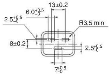
Unit: mm

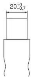
⑤ Cabinet Dimensions
Unit: mm (inch)


CAUTION:
Do not attempt to mount the projector on a ceiling yourself.
The projector must be installed by qualified technicians in order to ensure proper operation and reduce the risk of bodily injury.
In addition, the ceiling must be strong enough to support the projector and the installation must be in accordance with any local building codes. Please consult your dealer for more information.
6 Pin assignments and signal names of main terminals
COMPUTER IN/ Component Input Terminal (Mini D-Sub 15 Pin)
Connection and signal level of each pin

Signal Level
Video signal : 0.7Vp-p (Analog)
Sync signal : TTL level
| Pin No. | RGB Signal (Analog) | YCbCr Signal | |
| 1 Red | Cr | ||
| 2 | Green or Sync on Green Y | ||
| 3 Blue | Cb | ||
| 4 Ground | |||
| 5 Ground | |||
| 6 | Red Ground | Cr Ground | |
| 7 Green Ground | Y Ground | ||
| 8 Blue | Ground | Cb Ground | |
| 9 No Connection | |||
| 10 | Sync Signal Ground | ||
| 11 | No Connection | ||
| 12 | Bi-directional DATA (SDA) | ||
| 13 | Horizontal Sync or Composite Sync | ||
| 14 | Vertical Sync | ||
| 15 | Data Clock | ||
HDMI IN Terminal (Type A)

| Pin No. | Signal | Pin No. | Signal |
| 1 | TMDS Data 2+ | 11 | TMDS Clock Shield |
| 2 TMD | S Data 2 Shield | 12 TMD | S Clock- |
| 3 TMD | S Data 2- | 13 CEC | |
| 4 | TMDS Data 1+ | 14 | Disconnection |
| 5 | TMDS Data 1 Shield | 15 | SCL |
| 6 | TMDS Data 1- | 16 | SDA |
| 7 | TMDS Data 0+ | 17 | DDC/CEC grounding |
| 8 | TMDS Data 0 Shield | 18 | +5 V power supply |
| 9 | TMDS Data 0- | 19 | Hot plug detection |
| 10 | TMDS Clock + |
DisplayPort IN Terminal

| Pin No. | Signal | Pin No. | Signal |
| 1 | Main link lane 3- | 11 | Grounding 0 |
| 2 Grounding 3 | 12 Main | link lane 0+ | |
| 3 Main link lane 3+ | 13 Configuration 1 | ||
| 4 | Main link lane 2- | 14 | Configuration 2 |
| 5 | Grounding 2 | 15 | Supplementary channel + |
| 6 | Main link lane 2+ | 16 | Grounding 4 |
| 7 Main link lane 1- | 17 Supplementary channel - | ||
| 8 | Grounding 1 | 18 | Hot plug detection |
| 9 | Main link lane 1+ | 19 | Return |
| 10 | Main link lane 0- | 20 | +3.3 V power supply |
Ethernet/HDBaseT Port (RJ-45)
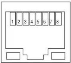
| Pin No. Signal |
| 1 TxD+/HDBT0+ |
| 2 TxD-/HDBT0- |
| 3 RxD+/HDBT1+ |
| 4 Disconnection/HDBT2+ |
| 5 Disconnection/HDBT2- |
| 6 RxD-/HDBT1- |
| 7 Disconnection/HDBT3+ |
| 8 Disconnection/HDBT3- |
USB Port (Type A)

| Pin No. Signal | |
| 1 | V_BUS |
| 2 | D- |
| 3 | D+ |
| 4 Grounding | |
PC CONTROL Port (D-Sub 9 Pin)

Communications protocol
| Pin No. Signal | |
| 1 Unused | |
| 2 | RxD reception data |
| 3 TxD | transmission data |
| 4 Unused | |
| 5 Grounding | |
| 6 Unused | |
| 7 | RTS transmission request |
| 8 CTS | transmission allowed |
| 9 Unused | |
⑦ Changing the Background Logo (Virtual Remote Tool)
This will help you perform operations such as projector's power on or off and signal selection via a LAN connection. It is also used to send an image to the projector and register it as the logo data of the projector. After registering it, you can lock the logo to prevent it from changing.
Control Functions
Power On/Off, signal selection, picture freeze, picture mute, audio mute, Logo transfer to the projector, and remote control operation on your PC.
Virtual Remote screen
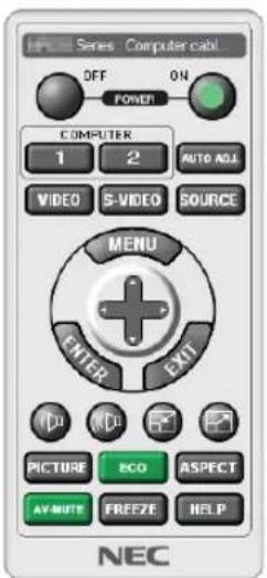
Remote Control Window Toolbar

For getting the Virtual Remote Tool, please visit our web site and download it: http://www.nec-display.com/dl/en/index.html
NOTE:
- Logo data (graphics) that can be sent to the projector with Virtual Remote Tool has the following restrictions: (Only via serial or LAN connection)
* File size: Within 256 kilobytes
* Image size: Within the resolution of the projector
* File format: PNG (Full color)
- Logo data (image) sent using the Virtual Remote Tool will be displayed in the center with the surrounding area in black.
- To put the default "NEC logo" back in the background logo, you need to register it as the background logo by using the image file (\Logo\NEC_logo2015_1920x1200.png) included on the supplied NEC Projector CD-ROM.
8 Troubleshooting
This section helps you resolve problems you may encounter while setting up or using the projector.
Indicator Messages
POWER Indicator
| Indicator display Projector status Procedure | |||
| Off Power is off. - | |||
| Flashing | Blue (short flashes) Preparing to turn power on Wait a while. | ||
| Blue (long flashes) Off timer (enabled) Program timer (off time enabled) | - | ||
| Orange (short flashes) Projector cooling Wait a while. | |||
| Orange (long flashes) Program timer (on time enabled) - | |||
| Lit Blue Power on | - | ||
| Red | Standby mode (NORMAL) | ||
| Orange | Standby mode (NETWORK STANDBY) - | ||
STATUS Indicator
| Indicator display | Projector status | Procedure | |
| Off | No problem, or STANDBY MODE - “NETWORK STANDBY” | - | |
| Flashing | Red (once per cycle) | Lens is not fixed on. | Check fixing conditions of the lens. |
| Red (four times per cycle) | Fan problem | The cooling fan has stopped turning. Contact an NEC projector customer support center for repairs. | |
| Green (twice per cycle) | Performing the lens calibration | - | |
| Orange (once per cycle) | Network conflict | It is not possible to connect the projector's built-in LAN and wireless LAN simultaneously to the same network. To connect the projector's built-in LAN and wireless LAN simultaneously, connect them to different networks.In the STANDBY state, the status indicator does not flash in Orange even if the network conflict is occurred. | |
| Orange (twice per cycle) | Trouble occurrence while the lens shift is functioned as accidentally cutting off the power supply. | Carry out the lens calibration | |
| Lit Green | STANDBY MODE in sleep mode* - | ||
| Orange | Button has been pressed while projector is in key lock mode | The projector's keys are locked. The setting must be canceled to operate the projector. (→ Page 126) | |
| Projector's ID number and remote control's ID number do not match | Check the control IDs. (→ Pages 127) | ||
* Sleep mode refers to the state whereby the functional restrictions due to the standby mode setting are removed.
LIGHT Indicator
| Indicator display Projector status Procedure | |||
| Off | The light module is turned off. | - | |
| Flashing | Red (six times per cycle) | The light source is not turned on. | Wait for over 1 minute and try to power ON the projector again. If the problem still persists, contact the NEC projector customer support center. |
| Lit Green | Light module lit - | ||
TEMP. Indicator
| Indicator display Projector status Procedure | |||
| Off No problem | |||
| Flashing | Red (cycles of 2) | Temperature problem The temperature protector has been activated. If the room temperature is high, move the projector to a cool place. If the problem still persists, contact the NEC projector customer support center. | |
| Lit Orange | High surrounding temperature (Forced ECO Mode) | The surrounding temperature is high. Lower the room temperature. | |
If the temperature protector is activated
If the projector's internal temperature rises abnormally, the light module turns off and the temperature indicator flashes (repeatedly two flashes per cycle).
It may happen that the projector's temperature protector is simultaneously activated and the projector's power turns off.
If this happens, do the following:
- Unplug the power cord from the power outlet.
- If using in a place where the surrounding temperature is high, move the projector to a different, cool place.
- If there is dust in the ventilation slits, clean. (→ page 160)
- Wait as such about 1 hour for the projector's internal temperature to lower.
Common Problems & Solutions
(→ "POWER/STATUS/LIGHT/TEMP. Indicator" on page 178, 179.)
| Problem Check These Items | |
| Does not turn on or shut down | Check that the power cord is plugged in and that the power button on the projector cabinet or the remote control is on. (→ pages 14, 17)Check to see if the projector has overheated. If there is insufficient ventilation around the projector or if the room where you are presenting is particularly warm, move the projector to a cooler location.The light module may fail to light. Wait a full minute and then turn on the power again.In case it's hard to think the trouble is not caused on the above mentioned conditions, unplug the power cord from the outlet. Then wait 5 minutes before plugging it in again. (→ page 34) |
| Will turn off | Ensure that the [OFF TIMER], [AUTO POWER OFF] or [PROGRAM TIMER] is off. (→ page 122, 137) |
| No picture | Check if the appropriate input is selected. (→ page 20) If there is still no picture, press the SOURCE button or one of the source buttons again.Ensure your cables are connected properly.Use menus to adjust the brightness and contrast. (→ page 95)Check that the SHUTTER (lens shutter) or AV MUTE (image off) buttons are not pressed.Check the [POWER ON SHUTTER] in the onscreen menu is not set to [CLOSE].Reset the settings or adjustments to factory preset levels using the [RESET] in the Menu. (→ page 138)Enter your registered keyword if the Security function is enabled. (→ page 45)If the HDMI IN or the DisplayPort IN signal cannot be displayed, try the following.- Reinstall your driver for the video card built in your computer, or use the updated driver.For reinstalling or updating your driver, refer to the user guide accompanied with your computer or video card, or contact the support center for your computer manufacturer.Install the updated driver or OS on your own responsibility.We are not liable for any trouble and failure caused by this installation.Signals may not be supported depending on the HDBaseT transmission device. IR and RS232C cannot be used in certain cases as well.Both the composite video signal from each input terminal as the computer, BNC IN, and BNC (CV), and the S-video signal from the BNC (Y/C) Input terminal are not output from HDMI OUT terminal of this projector.Be sure to connect the projector and notebook PC while the projector is in standby mode and before turning on the power to the notebook PC.In most cases the output signal from the notebook PC is not turned on unless connected to the projector before being powered up.* If the screen goes blank while using your remote control, it may be the result of the computer's screen-saver or power management software.See also the page 182. |
| Picture suddenly becomes dark | Check if the projector is in the Forced ECO mode because of too high ambient temperature. |
| Color tone or hue is unusual | Check if an appropriate color is selected in [WALL COLOR]. If so, select an appropriate option. (→ page 117)Adjust [HUE] in [PICTURE]. (→ page 95) |
| Image isn't square to the screen | Reposition the projector to improve its angle to the screen. (→ page 22)Use the Keystone correction function to correct the trapezoid distortion. (→ page 42) |
| Picture is blurred | Adjust the focus. (→ page 26)Reposition the projector to improve its angle to the screen. (→ page 22)Ensure that the distance between the projector and screen is within the adjustment range of the lens. (→ page 161)Has the lens been shifted by an amount exceeding the guaranteed range? (→ page 164)Condensation may form on the lens if the projector is cold, brought into a warm place and is then turned on. Should this happen, let the projector stand until there is no condensation on the lens. |
| Image is scrolling vertically, horizontally or both | Check the computer's resolution and frequency. Make sure that the resolution you are trying to display is supported by the projector. (→ page 167)Adjust the computer image manually with the Horizontal/Vertical in the [IMAGE OPTIONS]. (→ page 97) |
| Remote control does not work | Install new batteries. (→ page 11)Make sure there are no obstacles between you and the projector.Stand within 22 feet (7 m) of the projector. (→ page 12) |
| Indicator is lit or blinking | See the POWER/STATUS/LIGHT/TEMP. Indicator. (→ page 178, 179) |
| Cross color in RGB mode | Press the AUTO ADJ. button on the projector cabinet or the remote control. (→ page 33)Adjust the computer image manually with [CLOCK]/[PHASE] in [IMAGE OPTIONS] in the menu. (→ page 96) |
For more information contact your dealer.
If there is no picture, or the picture is not displayed correctly.
• Power on process for the projector and the PC.
Be sure to connect the projector and notebook PC while the projector is in standby mode and before turning on the power to the notebook PC.
In most cases the output signal from the notebook PC is not turned on unless connected to the projector before being powered up.
NOTE: You can check the horizontal frequency of the current signal in the projector's menu under Information. If it reads "0kHz", this means there is no signal being output from the computer. (→ page 139 or go to next step)
- Enabling the computer's external display.
Displaying an image on the notebook PC's screen does not necessarily mean it outputs a signal to the projector. When using a PC compatible laptop, a combination of function keys will enable/disable the external display. Usually, the combination of the "Fn" key along with one of the 12 function keys gets the external display to come on or off. For example, NEC laptops use Fn + F3, while Dell laptops use Fn + F8 key combinations to toggle through external display selections.
• Non-standard signal output from the computer
If the output signal from a notebook PC is not an industry standard, the projected image may not be displayed correctly. Should this happen, deactivate the notebook PC's LCD screen when the projector display is in use. Each notebook PC has a different way of deactivate/reactivate the local LCD screens as described in the previous step. Refer to your computer's documentation for detailed information.
• Image displayed is incorrect when using a Mac
When using a Mac with the projector, set the DIPswitch of the Mac adapter (not supplied with the projector) according to your resolution. After setting, restart your Mac for the changes to take affect.
For setting display modes other than those supported by your Mac and the projector, changing the DIP switch on a Mac adapter may bounce an image slightly or may display nothing. Should this happen, set the DIP switch to the 13" fixed mode and then restart your Mac. After that, restore the DIP switches to a displayable mode and then restart the Mac again.
NOTE: A Video Adapter cable manufactured by Apple Computer is needed for a MacBook which does not have a mini D-Sub 15-pin terminal.
• Mirroring on a MacBook
* When using the projector with a MacBook, output may not be set to 1024 × 768 unless “mirroring” is off on your MacBook. Refer to owner’s manual supplied with your Mac computer for mirroring.
- Folders or icons are hidden on the Mac screen
Folders or icons may not be seen on the screen. Should this happen, select [View] → [Arrange] from the Apple menu and arrange icons.
⑨ PC Control Codes and Cable Connection
PC Control Codes
Function Code Data
| POWER | ON | 02H | 00H | 00H | 00H | 00H | 02H | ||||
| POWER | OFF | 02H | 01H | 00H | 00H | 00H | 03H | ||||
| INPUT | SELECT | HDMI | 02H | 03H | 00H | 00H | 02H | 01H | A1H | A9H | |
| INPUT | SELECT | DisplayPort | 02H | 03H | 00H | 00H | 02H | 01H | A6H | AEH | |
| INPUT | SELECT | BNC | 02H | 03H | 00H | 00H | 02H | 01H | 02H | 0AH | |
| INPUT | SELECT | BNC(CV) | 02H | 03H | 00H | 00H | 02H | 01H | 06H | 0EH | |
| INPUT | SELECT | BNC(Y/C) | 02H | 03H | 00H | 00H | 02H | 01H | 0BH | 13H | |
| INPUT | SELECT | COMPUTER | 02H | 03H | 00H | 00H | 02H | 01H | 01H | 09H | |
| INPUT | SELECT | HDBaseT | 02H | 03H | 00H | 00H | 02H | 01H | 20H | 28H | |
| INPUT | SELECT | SLOT | 02H | 03H | 00H | 00H | 02H | 01H | ABH | B3H | |
| PICTURE | MUTE | ON | 02H | 10H | 00H | 00H | 00H | 12H | |||
| PICTURE | MUTE | OFF | 02H | 11H | 00H | 00H | 00H | 13H | |||
NOTE: Contact your local dealer for a full list of the PC Control Codes if needed.
Cable Connection
Communication Protocol
Baud rate 38400 bps
Data length 8 bits
Parity....No parity
Stop bit....One bit
X on/off......None
Communications procedure......Full duplex
NOTE: Depending on the equipment, a lower baud rate may be recommended for long cable runs.
PC Control Terminal (D-SUB 9P)
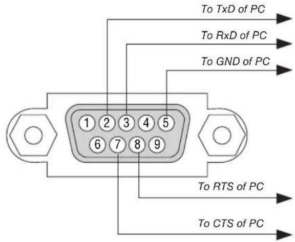
NOTE 1: Pins 1, 4, 6 and 9 are no used.
NOTE 2: Jumper "Request to Send" and "Clear to Send" together on both ends of the cable to simplify cable connection.
NOTE 3: For long cable runs it is recommended to set communication speed within projector menus to 9600 bps.
10 Troubleshooting Check List
Before contacting your dealer or service personnel, check the following list to be sure repairs are needed also by referring to the “Troubleshooting” section in your user’s manual. This checklist below will help us solve your problem more efficiently.
* Print this page and the next page for your check.
Frequency of occurrence □ always □ sometimes (How often?____) □ other (____)
Power
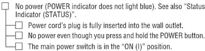
![Shut down during operation. Power cord's plug is fully inserted into the wall outlet. [AUTO POWER OFF] is turned off (only models with the [AUTO POWER OFF] function). [OFF TIMER] is turned off (only models with the [OFF TIMER] function).](/content/2026/05/957502/images/35c38adefeefcfc7a6e643cf6658f99f988746e49c8a8066c638fb613525be79.jpg)
Video and Audio
![No image is displayed from your PC or video equipment to the projector. Still no image even though you connect the projector to the PC first, then start the PC. Enabling your notebook PC's signal output to the projector. A combination of function keys will enable/disable the external display. Usually, the combination of the "Fn" key along with one of the 12 function keys turns the external display on or off. No image (blue or black background, no display). Still no image even though you press the AUTO ADJUST button. Still no image even though you carry out [RESET] in the projector's menu. Signal cable's plug is fully inserted into the input terminal A message appears on the screen. ( _________ ) The source connected to the projector is active and available. Still no image even though you adjust the brightness and/or the contrast. Input source's resolution and frequency are supported by the projector. Image is too dark. Remains unchanged even though you adjust the brightness and/or the contrast. Image is distorted. Image appears to be trapezoidal (unchanged even though you carry out the [KEYSTONE] adjustment).](/content/2026/05/957502/images/bc516e8f2726f877317c84b1bc56c946427456c6d88e9d97f38764833edb0367.jpg)
![Parts of the image are lost. Still unchanged even though you press the AUTO ADJUST button. Still unchanged even though you carry out [RESET] in the projector's menu. Image is shifted in the vertical or horizontal direction. Horizontal and vertical positions are correctly adjusted on a computer signal. Input source's resolution and frequency are supported by the projector. Some pixels are lost. Image is flickering. Still unchanged even though you press the AUTO ADJUST button. Still unchanged even though you carry out [RESET] in the projector's menu. Image shows flickering or color drift on a computer signal. Still unchanged even though you change [FAN MODE] from [HIGH] to [AUTO]. Image appears blurry or out of focus. Still unchanged even though you checked the signal's resolution on PC and changed it to projector's native resolution. Still unchanged even though you adjusted the focus.](/content/2026/05/957502/images/54524d1387c10319b6c09a3c9ed1f8822f19021ee5c6ee8b7543784714e21c35.jpg)
Other
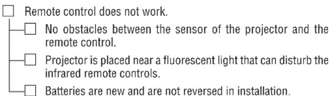
![Buttons on the projector cabinet do not work (only models with the [CONTROL PANEL LOCK] function) [CONTROL PANEL LOCK] is not turned on or is disabled in the menu. Still unchanged even though you press and hold the SOURCE button for a minimum of 10 seconds.](/content/2026/05/957502/images/53cf3044ebe5e04bb50a433d68690885c82c97e2acfbb371b3b14924dd9f4bd1.jpg)
In the space below please describe your problem in detail.
Information on application and environment where your projector is used
Projector
Model number:
Serial No.:
Date of purchase:
Light module operating time (hours):
Eco Mode: □ OFF □ ON
Information on input signal:
Horizontal synch frequency [ ] kHz
Vertical synch frequency [ ] Hz
Synch polarity H □ (+) □ (−)
V
Synch type □ Separate □ Composite
□ Sync on Green
STATUS Indicator:
Steady light □ Orange □ Green
Flashing light [ ] cycles
Remote control model number:

flowchart
graph TD
    A["Projector"] -->|Cable| B["PC"]
    A --> C["Blu-ray player"]
Signal cable
NEC standard or other manufacturer's cable?
Model number: Length: inch/m
Distribution amplifier
Model number:
Switcher
Model number:
Adapter
Model number:
Installation environment
Screen size: inch
Screen type: □ White matte □ Beads □ Polarization
□ Wide angle □ High contrast
Throw distance: feet/inch/m
Orientation: □ Ceiling mount □ Desktop
Power outlet connection:
□ Connected directly to wall outlet
□ Connected to power cord extender or other (the number of connected equipment____)
- ) □ Connected to a power cord reel or other (the number of connected equipment ____)
Computer
Manufacturer:
Model number:
Notebook PC □ / Desktop □
Native resolution:
Refresh rate:
Video adapter:
Other:
Video equipment
VCR, Blu-ray player, Video camera, Video game or other
Manufacturer:
Model number:
NEC
- NOTES
- Safety Cautions
- Precautions
- CAUTION
- DOC Compliance Notice (for Canada only)
- Machine Noise Information Regulation - 3. GPSGV,
- Disposing of your used product
- In the European Union
- Outside the European Union
- WARNING TO CALIFORNIA RESIDENTS:
- RF Interference
- WARNING
- Important Safeguards
- Installation
- Fire and Shock Precautions
- Caution on Handling the Optional Lens
- Precautions when installing or replacing the lens unit sold separately (LENS CALIBRATION)
- Remote Control Precautions
- Light Module
- Laser Safety Caution
- CAUTION – CLASS 3R OF IEC 60825-1 SECOND EDITION LASER PRODUCT
- NEC MODEL No.NP-PX1004UL-WH
- 110-240V\~
- 50/60Hz 11.6A-5.2A
- NEC MODEL No.NP-PX1004UL-BK
- About Copyright of original projected pictures:
- Turkish RoHS information relevant for Turkish market
- Health precautions to users viewing 3D images
- Power management function
- STANDBY MODE (Factory preset: NORMAL)
- AUTO POWER OFF (Factory preset: 1 hour)
- Clearance for Installing the Projector
- Example 1 – If there are walls on both sides of the projector.
- NOTE:
- Example 2 – If there is a wall behind the projector.
- Important Information......i
- Introduction......1
- Projecting an Image (Basic Operation)....13
- Convenient Features....36
- Multi-Screen Projection....66
- Using On-Screen Menu....80
- Connecting to Other Equipment....143
- Maintenance .... 160
- Appendix......161
- Introduction
- ① What's in the Box?
- Attaching/Removing the Dust Cap
- ② Introduction to the Projector
- General
- Light source · Brightness
- Videos
- - Slot for optional board
- • Simultaneous display of 2 images (PIP/PICTURE BY PICTURE)
- • Multi-screen projection using multiple projectors
- • Supports HDMI 3D format
- Network
- - Convenient utility software (User Supportware)
- - CRESTRON ROOMVIEW compatible
- Energy-saving
- • Energy-saving design with a standby power consumption of 0.30 watts or under
- - “LIGHT MODE” for low power consumption and “Carbon Meter” display
- About this user's manual
- ③ Part Names of the Projector
- Front/Top
- Terminals Features
- REMOTE Terminal (Stereo Mini)
- SLOT
- Service terminal
- ④ Part Names of the Remote Control
- Battery Installation
- Operating Range for Wireless Remote Control
- Using the Remote Control in Wired Operation
- Projecting an Image (Basic Operation)
- ① Flow of Projecting an Image
- Step 1
- Step 2
- Step 3
- Step 4
- Step 5
- Step 6
- Step 7
- Step 8
- ② Connecting Your Computer/Connecting the Power Cord
- Connect your computer to the projector.
- Connect the supplied power cord to the projector.
- CAUTION:
- Using the Supplied Power Cords
- Using the Power Cord Stopper
- Attaching the power cord stopper
- ③ Turning on the Projector
- Press the POWER) button on the projector cabinet or the POWER ON button on the remote control.
- Performing Lens Calibration
- Note on Startup screen (Menu Language Select screen)
- To select a menu language, follow these steps:
- Use the ▲, ▼, ◀ or ▶ button to select one of the 30 languages from the menu.
- Press the ENTER button to execute the selection.
- Selecting a Source
- Selecting the computer or video source
- Detecting the Signal Automatically
- Using the Remote Control
- Selecting Default Source
- Press the MENU button.
- Press the ▶ button to select [SETUP].
- Press the ▶ button to select [SOURCE OPTIONS].
- Press the ▼ button four times to select [DEFAULT INPUT SELECT] and press the ENTER button.
- Select a source as the default source, and press the ENTER button.
- Press the EXIT button three times to close the menu.
- Restart the projector.
- TIP:
- ⑤ Adjusting the Picture Size and Position
- Adjusting the vertical position of a projected image (Lens shift)
- Adjusting with buttons on the cabinet
- Press the LENS SHIFT/HOME POSITION button.
- Press the ▼▲◀ or ▶ button.
- Adjusting with the remote control
- Hold the CTL button and press the ECO/L-SHIFT button.
- Focus
- Applicable lens unit: NP16FL/NP17ZL/NP18ZL/NP19ZL/NP20ZL/NP21ZL
- Press the FOCUS +/- button until you can obtain the best focus.
- Applicable lens unit: NP31ZL
- Focus on the projected image around the optical axis. (Powered focus)
- Adjust the focus at the edges of the projected image. (Manual focus)
- This completes adjusting the projected image's overall focus.
- Applicable lens unit: NP39ML
- Adjust the focus at the edges of the projected image.
- Repeat steps 1 and 2 until the optimal focus can be obtained on whole image.
- Zoom
- Adjusting the Tilt Foot
- ⑥ Optimizing Computer Signal Automatically
- Adjusting the Image Using Auto Adjust
- ⑦ Turning off the Projector
- ⑧ After Use
- Convenient Features
- ① Turn off the light of the projector (LENS SHUTTER)
- ② Turning off the Image (AV-MUTE)
- ③ Turning Off the On-Screen Menu (On-Screen Mute)
- ④ Shift the On-Screen Menu displaying position
- Move the cursor by the ▶ button to the [SETUP] and then press the ENTER button.
- Move the cursor by the ▶ button to the [MENU2].
- Move the cursor by the ▼ button to the [MENU POSITION] and then press the ENTER.
- Move the cursor either TO [HORIZONTAL POSITION] or [VERTICAL POSITION] by pressing ▼ or ▲ button and then press ◀/▶ button to shift the On-Screen Menu.
- ⑤ Freezing a Picture
- Magnifying a Picture
- Press the D-ZOOM (+) button to magnify the picture.
- Press the ▲▼◀▶ button.
- Press the D-ZOOM (−) button.
- ⑦ Changing LIGHT MODE/Checking Energy-Saving Effect Using LIGHT MODE [LIGHT MODE]
- Press LIGHT button on the cabinet.
- Press the ENTER button.
- Use the ▼▲ buttons to make a selection, and press the ENTER button.
- Checking Energy-Saving Effect [CARBON METER]
- ⑧ Correcting Horizontal and Vertical Keystone Distortion [CORNERSTONE]
- Project an image so that the screen is smaller than the area of the raster.
- Pick up any one of the corners and align the corner of the image with a corner of the screen.
- Press the 3D REFORM button.
- Move the cursor onto [MODE] by ▼ button and press the ENTER.
- Press the ◀ or ▶ button to highlight the [OK] and press the ENTER button.
- ⑨ Preventing the Unauthorized Use of the Projector [SECURITY]
- To enable the Security function:
- To disable the SECURITY function:
- Select [SETUP] → [CONTROL] → [SECURITY] and press the ENTER button.
- Select [OFF] and press the ENTER button.
- Type in your keyword and press the ENTER button.
- ⑩ Projecting 3D videos
- Health precautions
- Procedure to watch 3D videos using this projector
- Using a 3D emitter
- 3D eyewear and 3D emitter preparations
- Turn on the power supply of the 3D eyewear and wear the eyewear to watch the video.
- Using DLP® Link
- When videos cannot be viewed in 3D
- ⑪ Controlling the Projector by Using an HTTP Browser
- Overview
- Setting for wired network (NETWORK SETTINGS)
- Setting Alert Mail (ALERT MAIL)
- Operating the projector
- Setting PJLink PASSWORD, AMX BEACON, and CRESTRON.
- Preparation before Use
- Handling of the Address for Operation via a Browser
- PROJECTOR ADJUSTMENT
- NETWORK SETTINGS
- - SETTINGS
- CRESTRON
- LENS CONTROL
- • CONTROL
- - LENS MEMORY
- • REF. LENS MEMORY
- ⑫ Storing Changes for Lens Shift, Zoom, and Focus [LENS MEMORY]
- To store your adjusted values in [REF. LENS MEMORY]:
- To call up your adjusted values from [REF. LENS MEMORY]:
- Make sure [PROFILE] is highlighted, then press the ENTER button.
- Press the ▼/▲ buttons to select the [PROFILE] number, then press the ENTER button.
- Select [MOVE] and press the ENTER button.
- Multi-Screen Projection
- ① Things that can be done using multi-screen projection
- Case 1
- Case 2
- Case 1. Using a single projector to project two types of videos [PIP/PICTURE BY PICTURE]
- On-screen menu operations
- Case 2. Using four projectors (resolution: WUXGA) to project videos with a resolution of 2560 × 1600 pixels [TILING]
- Four similar videos are displayed when four projectors are projected.
- Operate the on-screen menu using the four respective projectors to divide the image into four portions.
- Adjust the lens shift of each projector to fine-tune the boundaries of the screen.
- Things to note when installing projectors
- ② Displaying Two Pictures at the Same Time
- Picture in Picture function (PIP)
- Picture by picture function (PICTURE BY PICTURE)
- Input terminals that can be used for the main screen and sub-screen.
- Projecting two screens
- Switching the main display with the sub-display and vice versa
- Restrictions
- ③ Displaying a Picture Using [EDGE BLENDING]
- Before explaining use of the Edge Blending function
- Preparation:
- Setting the overlap of projection screens
- ① Enable [EDGE BLENDING].
- Select [EDGE BLENDING].
- Select [MODE] → [ON] and press the ENTER button.
- Select [RIGHT] for Projector A and [LEFT] for Projector B.
- Select [CONTROL] → [ON] and press the ENTER button.
- ② Adjust [RANGE] and [POSITION] to determine an area of overlapped edges of images projected from each projector.
- Adjust [RANGE].
- Adjust [POSITION].
- BLEND CURVE
- Selecting an option for the [BLEND CURVE]
- Black Level Adjustment
- Example: Adjusting the Black Level when placing two projectors side by side
- Select [DISPLAY] → [EDGE BLENDING] → [BLACK LEVEL] and press the ENTER button.
- Use the ▼ or ▲ button to select an item and use the ◀ or ▶ to adjust the black level.
- 9-segmented portions for Black Level adjustment
- Using On-Screen Menu
- ① Using the Menus
- ② Menu Elements
- Menu windows or dialog boxes typically have the following elements:
- ③ List of Menu Items
- ④ Menu Descriptions & Functions [INPUT]
- HDMI
- DisplayPort
- BNC
- BNC(CV)
- BNC(Y/C)
- COMPUTER
- HDBaseT
- SLOT
- ENTRY LIST
- TEST PATTERN
- Using the Entry List
- Displaying the Entry list
- Press the ◀ or ▶ button to select [INPUT].
- Use the ◀, ▶, ▲, or ▼ to select [ENTRY LIST] and press the ENTER button.
- Cutting a signal from the Entry List [ (CUT)]
- Copying and pasting a signal from the Entry List [ (COPY)] / [ (PASTE)]
- Deleting all the signals from the Entry List [ALL DELTE)]
- ⑤ Menu Descriptions & Functions [ADJUST]
- [PICTURE]
- [MODE]
- [PRESET]
- [DETAIL SETTINGS]
- [GENERAL]
- Storing Your Customized Settings [REFERENCE]
- Selecting Gamma Correction Mode [GAMMA CORRECTION]
- Selecting Screen Size for DICOM SIM [SCREEN SIZE]
- Adjusting Color Temperature [COLOR TEMPERATURE]
- Adjusting Brightness and Contrast [DYNAMIC CONTRAST]
- Adjusting Brightness [LIGHT ADJUST]
- [Brilliant Color]
- Adjusting White Balance [WHITE BALANCE]
- [COLOR CORRECTION]
- [CONTRAST]
- [BRIGHTNESS]
- [SHARPNESS]
- [COLOR]
- [HUE]
- [RESET]
- [IMAGE OPTIONS]
- Adjusting Clock and Phase [CLOCK/PHASE]
- Adjusting Horizontal/Vertical Position [HORIZONTAL/VERTICAL]
- [BLANKING]
- Selecting Overscan Percentage [OVERSCAN]
- Selecting the Aspect Ratio [ASPECT RATIO]
- For Component/Video/S-Video signals
- [INPUT RESOLUTION]
- [VIDEO]
- Using Noise Reduction [NOISE REDUCTION]
- Selecting Interlaced Progressive Conversion Process Mode [DEINTERLACE]
- [CONTRAST ENHANCEMENT]
- [SIGNAL TYPE]
- [VIDEO LEVEL]
- [3D SETTINGS]
- FORMAT
- L/R INVERT
- Using the Lens Memory Function [LENS MEMORY]
- Move the cursor on [STORE] and press ENTER.
- ⑥ Menu Descriptions & Functions [DISPLAY]
- [PIP/PICTURE BY PICTURE]
- SUB INPUT
- MODE
- PICTURE SWAP
- PIP SETTING
- BORDER
- [GEOMETRIC CORRECTION]
- KEYSTONE
- CORNERSTONE
- HORIZONTAL CORNER/VERTICAL CORNER
- Adjustment method
- WARP
- PC TOOL
- RESET
- TOP/BOTTOM/LEFT/RIGHT
- BLACK LEVEL
- WHITE BALANCE
- PICTURE SETTING
- Conditions for using tiling
- ⑦ Menu Descriptions & Functions [SETUP]
- Selecting Menu Language [LANGUAGE]
- Selecting Menu Color [COLOR SELECT]
- Turning On / Off Source Display [INPUT DISPLAY]
- Turning messages on and off [MESSAGE DISPLAY]
- Turning ON/OFF Control ID [ID DISPLAY]
- [3D CAUTION MESSAGE]
- Selecting Menu Display Time [DISPLAY TIME]
- [MENU ANGLE]
- [MENU POSITION]
- TIP
- [INSTALLATION(1)]
- Selecting Projector Orientation [ORIENTATION]
- Selecting Aspect Ratio and Position for Screen [SCREEN TYPE]
- Using the Wall Color Correction [WALL COLOR]
- Selecting Fan Mode [FAN MODE]
- [LIGHT MODE]
- [REF. WHITE BALANCE]
- 3D GLASSES
- [SHUTTER SETTINGS]
- Using the Reference Lens Memory Function [REF. LENS MEMORY]
- [LENS CALIBRATION]
- [LENS POSITION]
- ADMINISTRATOR MODE
- PROGRAM TIMER
- Setting a new program timer
- Select [OK] and press the ENTER button.
- Select [J (BACK)] and press the ENTER button.
- Select [EXIT] and press the ENTER button.
- Activating the program timer
- Editing the programmed settings
- Changing the order of programs
- Deleting the programs
- DATE AND TIME SETTINGS
- [MOUSE]
- Disabling the Cabinet Buttons [CONTROL PANEL LOCK]
- Enabling Security [SECURITY]
- Selecting Communication Speed [COMMUNICATION SPEED]
- Setting ID to the Projector [CONTROL ID]
- Assigning or Changing the Control ID
- Turn on the projector.
- Press the ID SET button on the remote control.
- Press one of numeric keypad buttons while pressing and holding the ID SET button on the remote control.
- Example:
- Release the ID SET button.
- Turning On or Off Remote Sensor [REMOTE SENSOR]
- [NETWORK SETTINGS]
- Important:
- Hints on How to Set Up LAN Connection
- To set up the projector for a LAN connection:
- To recall LAN settings stored in the profile number:
- To connect a DHCP server:
- To receive error messages via e-mail:
- WIRED LAN
- PROJECTOR NAME
- DOMAIN
- ALERT MAIL
- NETWORK SERVICE
- [SOURCE OPTIONS]
- Setting Auto Adjust [AUTO ADJUST]
- [COLOR SYSTEM]
- Selecting Default Source [DEFAULT INPUT SELECT]
- Setting Closed Caption [CLOSED CAPTION]
- Selecting a Color or Logo for Background [BACKGROUND]
- [POWER OPTIONS]
- Selecting Power-saving in [STANDBY MODE]
- NETWORK STANDBY
- Enabling Direct Power On [DIRECT POWER ON]
- Turning On the Projector By Applying Computer Signal [AUTO POWER ON SELECT]
- Enabling Power Management [AUTO POWER OFF]
- Using Off Timer [OFF TIMER]
- Setting for the Optional Board [SLOT POWER]
- Returning to Factory Default [RESET]
- [CURRENT SIGNAL]
- [ALL DATA]
- [ALL DATA (INCLUDING ENTRY LIST)]
- ⑧ Menu Descriptions & Functions [INFO.]
- [SOURCE(2)]
- [SOURCE(4)]
- Connecting to Other Equipment
- ① Mounting a lens (sold separately)
- WARNING:
- Mounting the lens
- Remove the dust cap from the projector.
- Remove the lens cap on the back of the lens.
- Hold the lens unit aligning the labelled arrow on the unit coming top and insert the unit to the projector.
- Turn the lens unit rightward until click is heard.
- Removing the lens
- Before removing the lens:
- While pressing the LENS release button on the projector's front panel fully in, turn the lens counterclockwise.
- After slowly pulling the lens off the projector, release the LENS release button.
- ② Making Connections
- Analog RGB signal connection
- Digital RGB signal connection
- Cautions when connecting an HDMI cable
- Cautions when connecting a DisplayPort cable
- Cautions when using a DVI signal
- Connecting an External Monitor
- Connecting Your Blu-ray Player or Other AV Equipment
- Connecting Component Input
- Connecting HDMI Input
- Connecting to a Wired LAN
- Example of LAN connection
- Connecting to an HDBaseT transmission device (sold commercially)
- Connection example
- Portrait projection (vertical orientation)
- Precautions during installation
- Design and manufacturing conditions for the stand
- Reference drawings
- Stacking projectors
- Attaching Stacking Holders
- Remove rubber caps and screws at four locations.
- Attach the three stacking holders at four locations.
- Put another projector on the first projector.
- Maintenance
- ① Cleaning the Lens
- ② Cleaning the Cabinet
- ① Throw distance and screen size
- Lens types and throw distance
- Lens shifting range
- (Example) When using to project on a 150" screen
- ② Mounting the Optional Board (sold separately)
- Tighten the two screws on both sides of the slot.
- ③ Compatible Input Signal List
- Power Cord
- Power Cord Electrical Specifications
- Type of power cord
- Plug and cord
- Connector
- ⑤ Cabinet Dimensions
- Pin assignments and signal names of main terminals
- COMPUTER IN/ Component Input Terminal (Mini D-Sub 15 Pin)
- Ethernet/HDBaseT Port (RJ-45)
- USB Port (Type A)
- PC CONTROL Port (D-Sub 9 Pin)
- Communications protocol
- ⑦ Changing the Background Logo (Virtual Remote Tool)
- Control Functions
- Troubleshooting
- If the temperature protector is activated
- Common Problems & Solutions
- If there is no picture, or the picture is not displayed correctly.
- ⑨ PC Control Codes and Cable Connection
- PC Control Codes
- Cable Connection
- Troubleshooting Check List
- Power
- Video and Audio
- Other
- Information on application and environment where your projector is used
- Projector
- Signal cable
- Installation environment
- Video equipment
Brand : SHARP
Model : PX1004UL
Category : Video projector