
EN1262HT - Motion detector Inovonics - Free user manual and instructions
Find the device manual for free EN1262HT Inovonics in PDF.


| Product Type | High Traffic Motion Detector |
| Brand | Inovonics |
| Model | EN1262HT |
| Dimensions | 5.2 x 2 x 2.4 in (132 x 50 x 60 mm) |
| Weight | 4.2 oz (120 g) |
| Operating Temperature | 32°F to 120°F (0°C to 49°C) |
| Humidity | 0 - 93% (non-condensing) |
| Power Supply | Two Energizer L91 AA lithium 1.5V batteries |
| Typical Battery Life | 3 years |
| Detection Technology | Quad element PIR, pet immune |
| Coverage Area | 26 ft (8 m) |
| Mounting Height | 6.5 - 7.5 ft (2.1 - 2.3 m) |
| Warm-Up Period | 40 seconds |
| Check-In Time | 3 minutes |
| Tamper Protection | Housing and wall tamper switches |
| Pulse Count Options | Single or automatic (default: automatic) |
| Sleep Time Options | Fixed (180s) or variable (restart 180s), default: variable |
| Compliance | FCC Part 15, ISED RSS-102 |
| Installation | Wall or corner mount, indoor use only |
| Maintenance | Manual weekly testing recommended |
Frequently Asked Questions - EN1262HT Inovonics
User questions about EN1262HT Inovonics
0 question about this device. Answer the ones you know or ask your own.
Ask a new question about this device
Download the instructions for your Motion detector in PDF format for free! Find your manual EN1262HT - Inovonics and take your electronic device back in hand. On this page are published all the documents necessary for the use of your device. EN1262HT by Inovonics.
USER MANUAL EN1262HT Inovonics
EN1262HT High Traffic Motion Detector Installation and Operation Manual
1 Overview
The EN1262HT high traffic motion detector solves the battery limitation problems of motion sensors in commercial applications through an intelligent sleep timer and low current technology. It features a pet immune PIR detection element, and wall and housing tamper switches.
1.1 Inovonics Contact Information

For product and installation videos visit us at www.inovonics.com/videos or use the QR code below.

If you have any problems with this procedure, contact Inovonics technical support:
• E-mail: support@inovonics.com.
• Phone: (800) 782-2709; (303) 939-9336.
2 Installation and Startup
2.1 Installation Notes
• These products are designed to be maintained by professional security technicians.
- Products are tested for indoor use.
- All products should be manually tested weekly.
2.2 Mount the Housing and Install the Battery
- Loosen the captive housing screw.
- Open the housing.

natural_image
Line drawing of a door handle with a tool inserted, showing an upward arrow and a curved arrow (no text or symbols)Figure 1 Open the housing
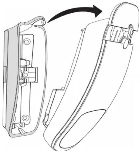
- Remove the EN1262HT from the mounting bracket per Figure 2.
natural_image
Technical line drawing of a mechanical component with an arrow indicating transformation (no text or symbols present)Figure 2 Remove the EN1262HT from the mounting bracket
-
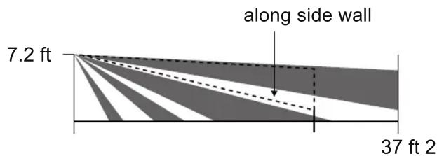
Noting the detection coverage in Figure 3, determine mounting location.
-
Avoid areas facing direct sunlight, areas that may change temperature rapidly, and areas where there are air ducts or substantial airflows.
- The recommended mounting height is 6.5 feet to 7.5 feet (2.1 to 2.3 m).
Side VIEW

other
| Dimension | Value | | --------- | --------- | | Top View | 26.2 ft | | Top View | 13.1 ft | | Top View | 6.6 ft | | Top View | 0 | | Top View | 6.6 ft | | Top View | 13.1 ft | | Top View | 26.2 ft | | Top View | 37 ft | | Top View | 89° |Figure 3 EN1262HT detection coverage area
-
Use the included mounting screws to mount the EN1262HT.
-
To mount on the wall, see Figure 4.
- To mount in a corner, see Figure 5.

natural_image
Technical line drawing of a mechanical component with a hatched top section and a central V-shaped base (no text or symbols)
natural_image
Technical line drawing of a mechanical device with mounting holes and internal components (no text or symbols)Figure 4 Wall mount configuration

natural_image
Technical diagram of a mechanical assembly with mounting bracket and internal components (no text or symbols)Figure 5 Corner mount configuration
- Install the battery per Figure 6.

natural_image
Diagram of a remote control casing showing internal components and two cylindrical batteries with positive and negative charge indicators (no text or labels)Figure 6 Install the battery
Note: When disposing of this device or depleted batteries, please do so in accordance with federal, state and local regulations.
2.3 Select Pulse Count
The pulse count options provides control for difficult operating environments. Automatic pulse count is recommended for reliable operation in environments subject to temperature fluctuation that can cause false alarms. The single pulse count mode is more sensitive to minor temperature variations, and should be used in sites where variant heat sources will not cause alarms. Automatic pulse count is the factory default because it allows more reliable operation in environments subject to temperature fluctuation. To select pulse count:
- Press the tamper button five times within three seconds.

natural_image
Technical line drawing of a remote control device showing internal components and a black arrow pointing to a component (no text or symbols present)Figure 7 Press the tamper button
- Wait for the green LED to blink five times, then:
- Press the tamper button one time within three seconds to select single pulse count.
- Press the tamper button two times within three seconds to select automatic pulse count.
- Confirm your selection.
- The green LED will blink once to indicate single pulse count has been selected; twice to confirm automatic pulse count has been selected.
2.4 Select Fixed/Variable Sleep Time
The sleep time setting provides control for normal or high-traffic operating environments. When set to fixed, if the EN1262HT senses motion, it will transmit an alarm, then enter sleep mode for 180 seconds; if motion is sensed when the sleep time has expired, the EN1262HT will transmit another alarm. When set to variable, if the EN1262HT senses motion, it will transmit an alarm, then enter sleep mode for 180 seconds; if motion is sensed before the sleep time has expired, the EN1262HT will restart the 180 second interval. Variable sleep time is the default setting as shipped from the factory. To select sleep time:
-
Press the tamper button four times within three seconds.
-
Wait for the green LED to blink four times, then:
- Press the tamper button one time within three seconds to select fixed sleep time.
- Press the tamper button two times within three seconds to select variable sleep time.
- Confirm your selection.
- The green LED will blink once to indicate fixed sleep time has been selected; twice to confirm variable sleep time has been selected.
2.5 Register the Transmitter
The EN1262HT must be registered with the system receiver in order to be monitored and supervised. Each EN1262HT has a unique factory-programmed identification number. Refer to the receiver, network coordinator or control panel installation instructions for details on registering a transmitter.
- When prompted to register the device, remove and replace the battery.
Note: Registration can only occur upon battery installation.
- Replace the housing cover.
Caution: The EN1262HT should be tested after registration to ensure operation. To test the EN1262HT, activate each of the conditions and ensure an appropriate response.
3 Test the EN1262HT
When in walk test mode the test LED will light red every time the EN1262HT senses motion. The unit will not transmit alarm signals during this test period. Once initiated, the walk test will last for ten minutes and then the EN1262HT will automatically return to normal operation. To initiate a walk test:
- Press the tamper button three times within three seconds.
Note: The test LED only lights red during the walk test.
4 Specifications
Dimensions: 5.2" x 2" x 2.4" (132 mm x 50 mm x 60 mm).
Weight: 4.2 ounces (120 grams)
Operating temperature: 32^ F to 120^ F ( 0^ C to 49^ C).
Humidity: 0 - 93% (non-condensing).
Battery: Two Energizer L91 AA lithium 1.5V batteries.
Typical battery life: Three years.
Tamper: Housing and wall.
PIR: Quad element PIR.
Coverage area: 26' (8m).
Warm up period: 40 seconds.
Check-in time: Three minutes.
5 Television and Radio Interference
This equipment has been tested and found to comply with the limits for a Class B digital device, pursuant to Part 15 of the FCC Rules. These limits are designed to provide reasonable protection against harmful interference in a residential installation. This equipment generates, uses and can radiate radio frequency energy and, if not installed and used in accordance with the instructions, may cause harmful interference to radio communications. However, there is no guarantee that interference will not occur in a particular installation. If this equipment does cause harmful interference to radio or television reception, which can be determined by
turning the equipment off and on, the user is encouraged to try to correct the interference by one or more of the following measures:
- Reorient or relocate the receiving antenna.
- Increase the separation between the equipment and receiver.
- Connect the equipment into an outlet on a circuit different from that to which the receiver is connected.
- Consult the dealer or an experienced radio/TV technician for help.
6 FCC Part 15 and Innovation, Science and Economic Development Canada (ISED) Compliance
This device complies with part 15 of the FCC Rules, and ISED license-exempt RSS standard(s). Operation is subject to the following two conditions: (1) this device may not cause interference, and (2) this device must accept any interference that may cause undesired operation of the device.
Caution: Changes or modifications not expressly approved by the party responsible for compliance could void the user's authority to operate the equipment.
7 Radiation Exposure Limits
7.1 FCC
This equipment complies with FCC radiation exposure limits set forth for an uncontrolled environment. In order to avoid the possibility of exceeding the FCC radio frequency exposure limits, human proximity to the antenna shall not be less than 20 cm during normal operation and must not be co-located or operating in conjunction with any other antenna or transmitter.
7.2 ISED
This equipment complies with ISED RSS-102 radiation exposure limits set forth for an uncontrolled environment. This transmitter must be installed to provide a separation distance of at least 20 cm from all persons and must not be co-located or operating in conjunction with any other antenna or transmitter.

- EN1262HT High Traffic Motion Detector Installation and Operation Manual
- Overview
- Inovonics Contact Information
- Installation and Startup
- Installation Notes
- Mount the Housing and Install the Battery
- Select Pulse Count
- Select Fixed/Variable Sleep Time
- Register the Transmitter
- Test the EN1262HT
- Specifications
- Television and Radio Interference
- FCC Part 15 and Innovation, Science and Economic Development Canada (ISED) Compliance
- Radiation Exposure Limits
- FCC
- ISED
Brand : Inovonics
Model : EN1262HT
Category : Motion detector