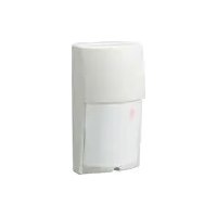
LX-802N - Motion detector OPTEX - Free user manual and instructions
Find the device manual for free LX-802N OPTEX in PDF.


| Product Type | Outdoor Passive Infrared Detector |
| Detection Method | Passive Infrared |
| Detection Area | 80 ft x 6.6 ft (24 m x 2 m) Long Range |
| Coverage - Multi-Level | 12 zones |
| Coverage - Pet Alley | 4 zones |
| Mounting Height (Multi-Level) | 8.3 ft (2.5 m) max |
| Mounting Height (Pet Alley) | 4-5 ft (1.2-1.5 m) |
| Detection Speed | 1-3.3 ft/sec (0.3-1.0 m/sec) |
| Sensitivity Adjustment | 3 positions: H, M, L |
| LED Indicator | Lights during detection |
| Alarm Period | 2 ± 1 sec (delay timer) |
| Alarm Output | NC/NO, 28V DC 0.2A max |
| Tamper Switch | Opens when cover removed |
| Pulse Count | 2 (20 ± 5 sec) or TEST (1 pulse) |
| Day/Night Mode Adjustment | Approx. 10 to 100,000 lux |
| Warm-up Period | Approx. 60 sec |
| Power Input | 10.8-13.2 VDC |
| Current Draw | 25 mA max |
| Mounting | Wall (Indoor/Outdoor) |
| Operating Temperature | -4°F to +122°F (-20°C to +50°C) |
| Environment Humidity | 95% max |
| Weight | 6.8 oz (190 g) |
| IP Rating | IP54 |
| Dimensions (H x W x D) | 5.56 x 2.95 x 2.27 in (141 x 75 x 57.5 mm) |
| Included Accessories | Masking strips (LX-402 only), mounting screws, sponge |
Frequently Asked Questions - LX-802N OPTEX
User questions about LX-802N OPTEX
0 question about this device. Answer the ones you know or ask your own.
Ask a new question about this device
Download the instructions for your Motion detector in PDF format for free! Find your manual LX-802N - OPTEX and take your electronic device back in hand. On this page are published all the documents necessary for the use of your device. LX-802N by OPTEX.
USER MANUAL LX-802N OPTEX
OUTDOOR PASSIVE INFRARED DETECTOR
LX-402,LX-802N
120°wide
Long Range


N219
1 YEAR WARRANTY
FEATURES
-LX-402 :40ft.(12m) 120° Wide Angle
-LX-802N:80ft.(24m) Long Range
-Selectable Detection Area Patterns
-Day/Night Mode
.Waterproof (IP Rating:IP54)
FUNCTION
-Selectable Pluse Count (TEST or 2)
-Selectable Sensitivity (H, M or L)
-Form C Relay Output
-Tamper Switch
OPTION
- Ceiling Mount Bracket : CA-2C
·Multi-Angle Wall Mount Bracket :CA-1W
Adjust ±45° (Horizontally)
Adjust 0 - 20° (Vertically downwards)
Safety-Related Precautions
Before installation, make sure to read this instruction manual carefully for safe and effective product operation.
·After reading this installation instructions, make sure to keep it in a conveninet place for future use.
| Warning | This icon denotes a situation involving the risk of serious injury or even death, if the warning given is ignored. | Caution | This icon denotes a situation involving the risk of serious injury or damage to property if the warning given is ignored. |

This icon indicates actions to be avoid. Details of the actions to be avoided are written beside or near icon.

This icon indicates instructions that should be strictly followed.

Warning
| Never use this product for any application expect purpose for detecting moving object such as human or car. In addition, never use for any activation for a shutter or other. It may cause hazards. | To avoid the risk of electric shock, never touch the main body of the product with wet hands (Also, if the product is wet after rain, do not touch it). |
| Never attempt to disassemble or modify the product, which increases the risk of fire or damage of the product. | Never connect the terminal with higher power supply or current draw over the specification. It increases the risk of fire or damage to the product. |
| Caution | |
| Avoid applying water directly from brackets, houses, or otherwise splashing water directly onto the product. It increases the risk of damaging the product. | Clean and inspect the device periodically for safe operation. If any defect is detected, ask your local shop to repair the device. |
1.INSTALLATION HINTS
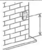
8.3 ft. (2.5m) max

Maximum mounting height is 8.3ft.(2.5m).
Mount the detector directly to a wall or ceiling with the optional bracket(model CA-1W or CA-2C).


Avoid moving objects in the detection area (i.e. swaying trees, bushes, etc.).

Aim the detector at wall or the ground, to aviod unwanted detection.

When using the pet alley area, the mounting height should be between 4-5ft.(1.2-1.5m).

Avoid looking directly at air conditioning or heating vents.

Avoid vapor or high humidity that can cause condensation.
2. DETECTION AREA PATTERNS
LX-402
A. TOP VIEW
B. SIDE VIEW
1.Multi-Level Area

2.Pet Alley Area

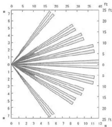
LX-802N
A. TOP VIEW

B. SIDE VIEW
1.Multi-Level Area

- Pet Alley Area

This product detects temperature differences between the moving object and the background temperature in the detection area. So, if the object dose not move, the detector can not detect it, and changing of the temperature differences may affect the detector's detection range.
Additionally, since this product has directional characteristic it is difficult to detect the target that is approaching the detector.
3.DESCRIPTION AND OPERATION
![Day/Night Mode Adjustment Adjust Day/Night Mode according to desired DAY/NIGHT operating periods. Inner Cover Pulse Count Switch [Standard"2"pluse or "TEST" mode. Mount Pitch 3.28 Inches (83.5 mm) Sensitivity Switch [Selectable 3 position] (H, M, L). Terminals Sensor (Do not touch) Knockout Multi-Le…](/content/2026/05/957302/images/7c5d585a629fbdbff041a9eb971778dcef244b0669ae73eab68854f929912f5d.jpg)
4.INSTALLATION PROCEDURE
Installation on wall


Installation on ceiling


Use optional ceiling mount bracket "CA-2C".
3 NOTE!

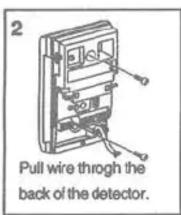
If you have problems of wiring through the back of the detector, remove adjustment screw and remove the PCB from the base.(see illus.)
4

Power supply wires should not exceed the following lengths.
| wires size | |
| AWG22(0.33 mm 2 ) | 1070ft(320m) |
| AWG20(0.52 mm 2 ) | 1700ft(510m) |
| AWG18(0.83 mm 2 ) | 2700ft(820m) |
5
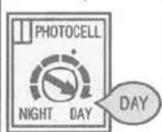
Set the Day/Night mode adjustment to the "24HR" setting(DAY).

Set Pulse Count to "TEST" mode. Adjust sensitivity setting (see section 6-2 and 3).
6
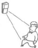
Replace the cover and supply power to unit.
After the warmup period is complete (approx. 60 sec.), conduct Walk Test.
The LED Indicator lights when the unit detects moving object.
7 After conducting Walk Test.

Set the Day/Night mode adjustment to the NORMAL position(·). (If night only operation is required, see section 6-1)

Set Pulse Count to the "2" position. (see section 6-1 and 2).
8
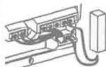
After wiring, pack the provided sponge into the opening between each wires and the knockout hole.
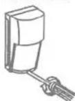
Select HIGH, MEDIUM or LOW sensitivity(H,M,L). Fasten cover with the cover screw. (see section 6-3)
5.OPTIONAL BRACKETS
Note ! Maximum mounting height is 8.3 ft (2.5m)
- Ceiling Mount Bracket "CA-2C"
Adjust Horizontally: ±45°
Adjust Vertically: 0° to 20° downward


- Multi-Angle Wall Mount Bracket "CA-1W"
Adjust Horizontally : ±45°
Adjust Vertically : 0° to 20° downward

1. Day/ Night Mode
Adjust the Day/Night Mode switch of the detector according to the brightness of the surrounding area.

NIGHT DAY
NORMAL Position
: To have the standard detector function only during evening/night time, set the dial to the reference position (·).

NIGHT DAY
: To have the detector begin to function while the surrounding area is lighter, turn the dial gradually to the DAY side.

NIGHT DAY
: To have the detector function only after it has become dark, turn the dial gradually to the NIGHT side.

NIGHT DAY
: To have the detector function at all time, or to perform a walk test, set the dial to the DAY position.
Unit is pre-set at "NORMAL" position.
2. Pulse Count Switch

"2" mode
: Select "2" for normal applications. (STANDARD Position)

"TEST" mode
: Select "TEST" mode when conducting WALK TEST, or for use in extremely stable environments.
Unit is pre-set at "2" position.
3. Sensitivity Switch

M
: Use "M" position for normal applications. (STANDARD Position)

H
: Use "H" Position when you need high sensitivity. (ex.Pet Alley Area)

。
: Use "L" position in areas that may be unstable.
Unit is pre-set at "M" position.
7. DETECTION AREA ADJUSTMENT
Changing vertical detection area
1.Multi-Level Area

Use this area for normal applications.
Unit is pre-set at "Multi-Level" setting.
2.Pet Alley Area
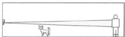
Provide a horizontal detection pattern with no declination of zones, allowing pets to move through the area.
Selecting Pet Alley Pattern

Carefully loosen the adjustment screw.

Slide the cover down and fasten the screw at the "P" position.

Flip the Mirror to the upper position.
NOTE! Sensitivity setting must be one step higher position when pet alley area is selected.
NOTE! Pet Alley Area will not function if two changes are not performed.
Eliminating unwanted detection zones
(LX-402 only)
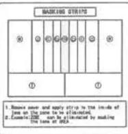
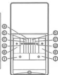
Unwanted detection zones can be eliminated by simply masking the lens with the provided masking strip, as follows:
1.

Remove cover and apply strip to the inside of lens on the zone to be eliminated.(see illus.)
2.
![graph TD A["Center"] --> B["a"] A --> C["b"] A --> D["c"] A --> E["d"] A --> F["e"] A --> G["f"] A --> H["g"] A --> I["h"] A --> J["j"] A --> K["k"] A --> L["l"]](/content/2026/05/957302/images/3f9bf2ae7cca2ac952a4561bc94b6864eef155c5741cabcd912de4357ceaae01.jpg)
Example: ZONE "a" can be eliminated by masking the lens at area "a" (see illus.).
8.TROUBLE SHOOTING
| PROBLEM | PROBABLE CAUSE | REMEDY |
| LED does not light up. | Improper power supply voltage. (disconnection, low voltage) | Confirm the power supply is under specification. |
| Wrong polarity | Switch positive and negative at terminal. | |
| The detector is in warm up period. | Wait for.(approx. 60 sec.) | |
| The Day/Nigth Mode Adjustment knob setting is inappropriate. | See section 6-1. Confirm the adjustment knob. | |
| Incorrect detection area. | See section 2. | |
| LED lights up even though no one is in detection area. | Moving object within area. (curtain, wall hanging, etc.) | Remove the object from the detection area. |
| Improper power supply voltage. | Confirm the power supply is under specification. | |
| The unit is detecting presons, cars or other objects beyond the set area. | Check the detection area. | |
| Temperature of object within area is changing rapidly (heater, air conditioning, etc.) | Remove the heat sources from the detection area. | |
| The LED lights up, but there is no relay output | Relay contact is stuck or damaged due to overloading. | Check load of output. The unit needs repair or replacement. |
| Faulty wiring. | Wire correctly. | |
| Alarm output connects to other devices as follows. when NC output is used:connect in parallel. when NO output is used:connect in series. | when NC output is used:connect in series. when NO output is used:connect in parallel. |
9.SPECIFICATIONS
| Model | LX-402 | LX-802N | |
| Detection method | Passive Infrared | ||
| Detection area | 40ft×50ft(12m×15m)120°wide | 80ft×6.6ft(24m×2m)Long range | |
| Coverage | Multi-Level Area | 40 zones | 12 zones |
| Pet Alley Area | 18 zones | 4 zones | |
| Mounting height | Multi-Level Area | 8.3ft (2.5m) max | |
| Pet Alley Area | 4-5ft (1.2-1.5m) | ||
| Detection speed | 1-3.3ft/sec. (0.3-1.0m/sec.) | ||
| Sensitivity adjustment | Selectable 3 position (H,M,L) | ||
| LED indicator | LED lights during detection | ||
| Alarm period | 2±1 sec.(Delay timer) | ||
| Alarm output | NC.NO.28V DC 0.2A max | ||
| Tamper switch | Opens when cover removed. | ||
| Pulse count | 2 (20±5 sec.) or TEST(1 pulse) | ||
| Day/Night Mode adjustment | Approx. 10 to 100,000 lux | ||
| Warm up period | Approx. 60 sec. | ||
| Power input | 10.8-13.2VDC | ||
| Current draw | 25 mA max | ||
| Mounting | Wall (Indoor/Outdoor) | ||
| Operating temperature | -4°F - +122°F(-20°C - +50°C) | ||
| Environment humidity | 95% max | ||
| Weight | 6.0oz (170g) | 6.8oz (190g) | |
| IP Rating | IP54 | ||
| Accessory | Masking strips (LX-402 only),Mounting screw,Sponge | ||
※ Specifications may be changed without prior notice for improvements.
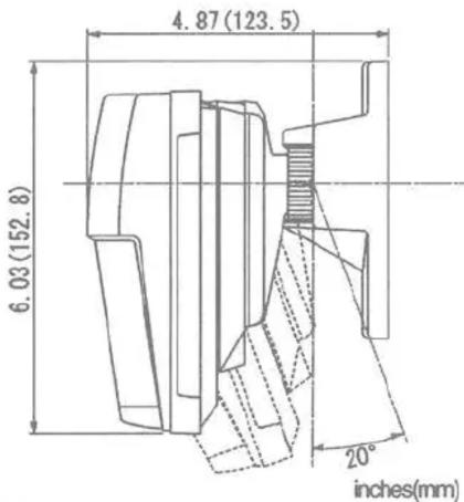
10.DIMENSIONS
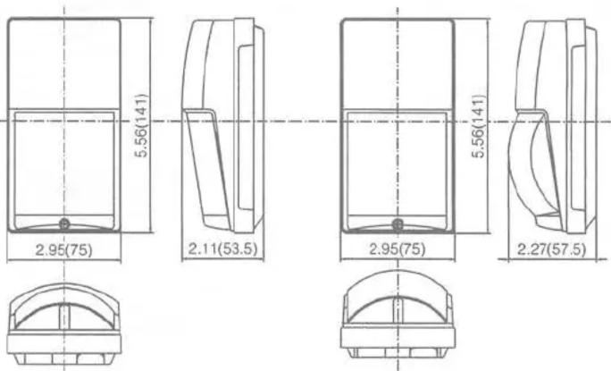
LX-402
LX-802N
inches(mm)

OPTEX
NOTE
These units are designed to detect movement of an intruder and activate an alarm control panel. Being only part of a complete alarm system, we cannot accept responsibility for any damages or other consequences resulting from an intrusion. These products conform to the EMC Directive 89/336 EEC.
OPTEX CO., LTD. (JAPAN)
(ISO 9001 Certified by LRQA)
(ISO 14001 Certified by JET)
5-8-12 Ogoto Oisi
Shiga
JAPAN TEL: +61 77 570 9670
TEL:+61-77-579-8810 FAX:+61-77-579-8120
URL:http://www.optex.co.jp/ef
OPTEX INCORPORATED (USA)
TEL: 1-909-993-577 Tech: (800)965-7839
URL: http://www.cplexamerica.com
OPTEX (EUROPE) LTD. (UK)
TEL +44-1628-631000
URL http://www.cptexeurope.com
OPTEX SECURITY SAS (FRANCE)
TEL:433-437-55-50-50 URL: http://www.orient-e
OPTEX SECURITY Sp.z o.o. (POLAND)
TEL +48-22-598-06-55
URL http://www.optex.com.pl
OPTEX KOREA CO., LTD. (KOREA)
TEL: +62-2-719-5971 URL: http://www.ase
URL:http://www.cptexkorea.com/
OPTEX (DONGGUAN) CO., LTD.
SHENZHEN OFFICE (CHINA)
TEL: +66-755-33382950


- LX-402,LX-802N
- FEATURES
- FUNCTION
- OPTION
- SAFETY-RELATED PRECAUTIONS
- WARNING
- 1.INSTALLATION HINTS
- DETECTION AREA PATTERNS
- 3.DESCRIPTION AND OPERATION
- 4.INSTALLATION PROCEDURE
- 5.OPTIONAL BRACKETS
- DAY/ NIGHT MODE
- NORMAL POSITION
- PULSE COUNT SWITCH
- SENSITIVITY SWITCH
- DETECTION AREA ADJUSTMENT
- OPTEX
- NOTE
- OPTEX CO., LTD. (JAPAN)
- OPTEX INCORPORATED (USA)
- OPTEX (EUROPE) LTD. (UK)
- OPTEX SECURITY SAS (FRANCE)
- OPTEX SECURITY SP.Z O.O. (POLAND)
- OPTEX KOREA CO., LTD. (KOREA)
- OPTEX (DONGGUAN) CO., LTD
Brand : OPTEX
Model : LX-802N
Category : Motion detector