
Redwall SIP-3020-IP-BOX - Motion detector OPTEX - Free user manual and instructions
Find the device manual for free Redwall SIP-3020-IP-BOX OPTEX in PDF.


| Product Type | Outdoor Long-Range IP Detector |
| Detection Technology | Dual photoelectric beam |
| Maximum Detection Range | Up to 200 m (outdoor) |
| Number of Beams | 2 |
| IP Connectivity | RJ45 Ethernet, PoE (IEEE 802.3af) |
| Dimensions (H × W × D) | 200 × 100 × 100 mm |
| Weight | 1.0 kg |
| Power Supply | 12 V DC or PoE |
| Power Consumption | 5 W (max) |
| Operating Temperature | -20°C to +55°C |
| Ingress Protection | IP65 |
| Alarm Output | Relay (NO/NC) and IP notification |
| Adjustable Sensitivity | Yes, via web interface |
| Anti-Masking | Yes |
| Mounting Bracket Included | Yes, wall/pole mount |
| Maintenance | Clean optical windows with soft, dry cloth |
| Safety | Do not look directly into the beam |
| Spare Parts | Replacement lenses and brackets available |
| Warranty | 2 years |
| Compliance | CE, RoHS |
Frequently Asked Questions - Redwall SIP-3020-IP-BOX OPTEX
User questions about Redwall SIP-3020-IP-BOX OPTEX
0 question about this device. Answer the ones you know or ask your own.
Ask a new question about this device
Download the instructions for your Motion detector in PDF format for free! Find your manual Redwall SIP-3020-IP-BOX - OPTEX and take your electronic device back in hand. On this page are published all the documents necessary for the use of your device. Redwall SIP-3020-IP-BOX by OPTEX.
USER MANUAL Redwall SIP-3020-IP-BOX OPTEX
Synthesized Intelligent PIR

REDWALL-V series
FEATURES
* Intelligent PIR Detection System
- Detection of ambient temperature and illuminance for automatic sensitivity management
- Advanced detection algorithm
- Three dual pyro-elements with patented Double Conductive Shielding
* Anti-vandalism functions
- Anti-rotation function with 3-axis accelerometer
- Anti-masking function with photo-beam
- Reinforced polycarbonate housing
- Max. 4 m (13 ft.) installation height
* Independent sensitivity selector for near/far areas
* Detection logic selector
* Detection range selector
* Independent N.C. and N.O. outputs
* Adjustable alarm interval time
• SIP-3020CAM DN (EU), SIP-3020CAM DN (US)
* High-quality camera image: Day (colour)/Night (B/W)
* 480 TV lines
* Varifocal lens 3-9 mm
* Minimum illumination: Day (colour) 0.5 lx, Night (B/W): 0.03 lx
: Synthesized Intelligent PIR
• SIP-3020
• SIP-4010
• SIP-404
: Synthesized Intelligent PIR
with D/N camera
• SIP-3020CAM DN (EU)
• SIP-3020CAM DN (US)
1 PARTS IDENTIFICATION

Near area mirror
*1: Not used for the SIP-4010 and SIP-404.

2 INSTALLATION AND MAINTENANCE NOTES
⚠ Warning Caution ⚠

Never repair or modify product

Hold the main unit securely when you install or service it. If you remove your hands from the main unit when cables are connected to it, the main unit may fall and the connector cables may break or the circuit board may be damaged.

Caution
Verify that the
power is off before
connecting the
wiring.
When servicing, the sensor can be hooked onto the base using the nylon wire loop.
2-1 INSTALLATION HINTS

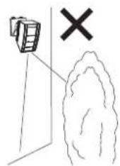

Mount the detector so that the majority of traffic flow is across the detection pattern.
3 INSTALLATION AND ANGLE ADJUSTMENT
3-1 Wall Mounting
(1) Attach the paper template (an accessory) onto the wall, and drill a 6-mm dia. mounting hole and a cabling hole. Insert the anchor bolt (an accessory) into the board mount hole.
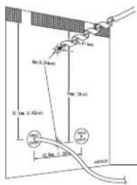
Distance from the ground to the bottom of the template must be between 2.3 m (7.6 ft.) and 4 m (13 ft.).
(2) Using an allen key, remove the main unit from the base.
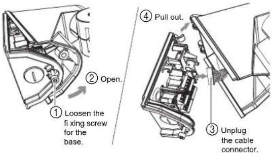
(3) Drill through the bushing of the wiring hole, pass the cable through the hole, and secure the base to the wall.

(4) Connect the cable to the terminal block (see Step 3-3).
(5) Mount the main unit onto the base.

Cautions>>
When mounting the main unit, take care not to trap the nylon wire loop. Also, take care not to get your fingers caught.
(6) Check to see that the various settings and operations are correct.
Caution>>
When the red LED flashes after the power turns on, this signifies that the system is warming up. Wait for approximately 60 seconds.
3-2 Inside View of the Base
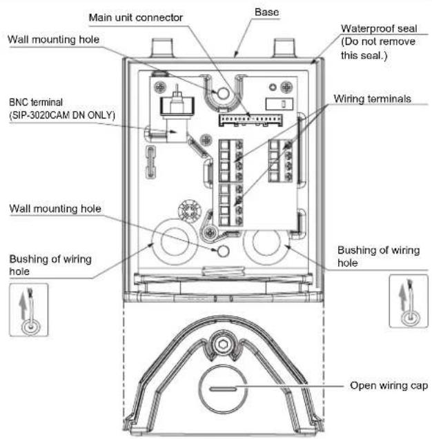
3-3 WIRING
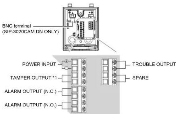
*1: TAMPER terminals to be connected to a 24 hour supervisory loop.
| Name Function | |
| TROUBLE OUTPUT | Trouble out is used for anti-masking signal. When an object is placed close to the lens surface, for a period of more than 20 seconds (approx.), the IR anti-masking circuit will activate and generate a trouble signal. |
| TAMPER OUTPUT | It is detected when the cover is opened. |
| It is detected when the main unit is removed from its base. | |
| Anti-Rotation:Damage sustained by the main unit is detected.When the system power switch is turned on while the cover is closed, the mounting position of the main unit itself will be determined and stored in memory after approximately 10 seconds. Then, if the main unit is impacted in a horizontal or vertical direction and if the position of the main unit has changed, damage sustained by the main unit will be detected. However, if you remove the cover while keeping the system power turned on, and if you close the cover again after correcting the position of the main unit, the new position of the main unit will be stored in memory after approximately 10 seconds. | |
Power wires should not exceed the following lengths.
| WIRE SIZE | SIP-3020/SIP-4010/SIP-404 | SIP-3020CAM DN (EU) SIP-3020CAM DN (US) | ||
| 12V DC | 14V DC 24 | V AC 12V | DC | |
| 0.33 mm2 (AWG22) | 580(1900) | 770(2530) | 1370(4490) | 100(330) |
| 0.52 mm2 (AWG20) | 910(2990) | 1210(3970) | 2160(7090) | 160(520) |
| 0.83 mm2 (AWG18) | 1450(4760) | 1930(6330) | 3450(11320) | 250(820) |
m (ft.)
4
DETECTION AREA SETTING
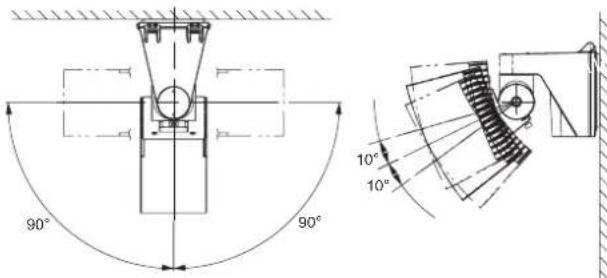
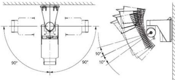
You can adjust the detection area by 90 degrees in a horizontal direction and by 10 degrees in a vertical direction. Correct the vertical detection angle according to the mounting height of the sensor unit.
Applicable models
SIP-3020 SIP-4010 SIP-404 SIP-3020CAM DN
Applicable models
SIP-3020 SIP-4010 SIP-404 SIP-3020CAM DN
Cautions>>
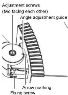
To rotate the main unit counterclockwise, loosen the RHside adjustment screw. To rotate the main unit clockwise, loosen the LH-side adjustment screw. Otherwise, you may find it difficult to tighten or you may find that you cannot tighten the adjustment screw when you are securing the main unit.
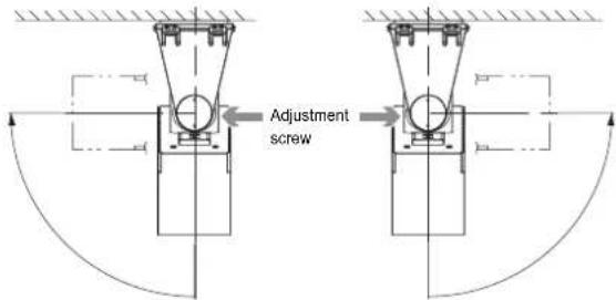
To rotate the unit counterclockwise
To rotate the unit clockwise
(1) Adjust the angle of the main unit in a horizontal direction so that you can cover the desired detection area.

④ Tighten the adjustment screw slightly.
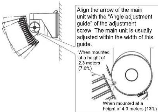
(2) Adjust the angle of the main unit in a vertical direction so that you can cover the desired detection area.
Cautions>>
If the mounting wall is at an angle, the arrow of the main unit may exceed the top or bottom limit of "Angle adjustment guide". Always check this using the area viewfinder or the walk tester. If the detection area is too high or too low, an object outside the detection area may be detected or incorrect object detection may occur.
(3) Remove the cover.
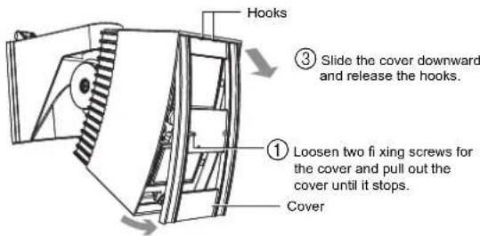
② Hold the heads of both cover fixing screws with your hands, and pull down and remove the bottom section of the cover from the main unit.
Cautions>>
The cover is linked to the main unit by nylon wire loop so that the cover does not fall. Do not pull the cover using excessive force.
(4) Mount the area viewfinder.

Mounting tips>>
- Engage the convex section of the area viewfinder fixing arms with the notches of the main unit, and insert and mount the arms.

- Mount the area plate so that an arrow of the plate center section faces upward and the letter surface can be seen.
- Insert the area plate into the top and bottom grooves of the area viewfinder until the plate is stopped by the ribs.
SIP-3020 SIP-40SIP-3020CAM DN


(5) Fine adjust the main unit angle in vertical and horizontal direction by observing the target area through the area viewfinder.
① To change the direction of the inspection window, rotate the area viewfinder in a horizontal direction until it clicks and stops.


Adjusting tips>>
If you experience any of the following, see Step 10.

The sensor area is extended over the street where a person walks or a car drives.
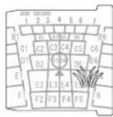
Branches of a tree and grass move when the wind blows.
Cautions>>
- The area viewfinder is a supporting tool for detection area adjustment.
- After you have adjusted the detection area using the area viewfinder, always check the area using the walk tester.
- Never look directly into the sun through the area view fi nder.
• After you have used the area viewfinder, store it away from direct sunlight.
(6) Securely tighten the adjustment screw that you have loosened.
(7) Connect the walk tester (optional) to the sensor unit, and check that the detection area is correct.
(OPM-WT) (AWT-3)
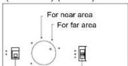
Use at "REDWALL" Power selector position. switch

Use at "REDWALL" Power selector position. switch

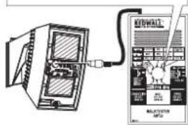
① When the power selector switch is turned to "POWER SUPPLY FROM SENSOR" position after plugging the cable into the walk tester connector, a continuous beeping sound will be heard.
② When a pedestrian first enters the detection area, the strong and weak beeps will sound alternately.
③ When the entirety of a pedestrian's body is detected, the strong beep will sound continuously.
Cautions>>
When you are checking the detection area, take care not to cover the shaded area of the window with the walk tester or its cable. If infrared beams to the sensor are partially shielded, the detection sensitivity will drop and the detection operation may fail.
If it is difficult to detect an object>>
- Set the detection logic switch to the "OR" position (see Step 5-2).
If the sensor is OK when you have completed the walk test, return the logic switch to the "AND" position. - Adjust the sensor sensitivity switch (see Step 5-1).
To mask the detection area>>
| Detection area | How to mask the area | Reference |
| Far area | Use the switch. | 5-3 |
| Use the masking plate (mounted in the main unit). | Step 7 | |
| Near area | Use the masking plate (mounted in the main unit). | 8-1 |
| Attach the masking seal (an accessory) to the area mirror surface. | 8-2 |
5 FUNCTION SETTING
Applicable models
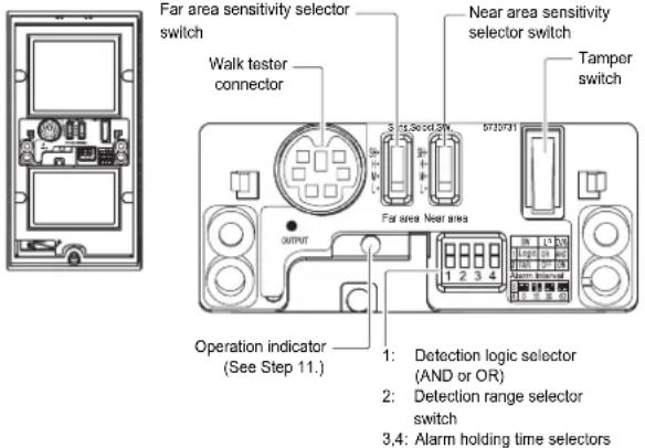
Cautions>>
If the red LED keeps blinking for approx. 60 seconds after turning the power on, turn the power off and then on again.
5-1 Sensitivity Selector Switch for Near and Far Area
Applicable models
SIP-3020 SIP-4010 SIP-404 SIP-3020CAM DN
You can change the sensitivity for far area detection and near area detection independently.

| SELECTOR POSITION | FUNCTION |
| SH | Suitable for sites requiring a level of sensitivity higher than “H” |
| H | Suitable for sites requiring a level of sensitivity higher than “M” |
| M (Factory default) | Suitable for standard applications |
| L | Suitable for hostile and narrow area |
5-2 Detection Logic Selector Switch
Dip switch 1
Applicable models
SIP-3020 SIP-4010 SIP-404 SIP-3020CAM DN
The near area sensor has two dual-element devices, and it covers two types of plane areas alternately using the two devices.

| SELECTOR POSITION | STATUS | FUNCTION |
| UP | OR (Factory default) | A sensor signal is output when an object is detected in either of the two detection areas.* Use this mode when you adjust the detection area. Switch to AND mode after you have finished the detection area adjustment. |
| DWN | AND | Use this mode to reduce instances of incorrect detection of objects. The sensor signal is output only when an object is detected within the two detection areas. If any objects are blocking multiple detection areas, use OR mode. |
5-3 Detection Range Selector Switch
Dip switch 2
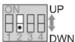
| SELECTOR POSITION | STATUS | FUNCTION |
| UP | OFF | Cancels the far area detection. The detection area is reduced as shown below. |
| DWN | ON (Factory default) | Enables the far area detection. |
![| Distance [m] | SIP-3020 | SIP-4010 | SIP-404 | SIP-3020CAM DN | | ------------ | -------- | -------- | ------- | -------------- | | 0 | 13 | 13 | 13 | 13 | | 1 | ~8 | ~7 | ~6 | ~5 | | 2 | ~5 | ~4 | ~3 | ~2 | | 4 | ~3 | ~2 | ~1 | ~1 |](/content/2026/05/1008244/images/bcb6ee1507a13f6c019c087f4345c15fa5c2b32c0d651e07453ee34b45cf5f15.jpg)
Cautions>>
If you cancel the far area detection, the detection distance is limited to approximately 20 meters (65ft.). Be sure to readjust and check the detection area using the area viewfinder and the walk tester.
5-4 Alarm Interval Switch
Dip switch 3-4
Applicable models
SIP-3020 SIP-4010 SIP-404 SIP-3020CAM DN
You can set an interval (4 different times) to suspend the alarm signal output.
For example, if you set this interval to 30 seconds, no more alarm signals will be output for 30 seconds after the output of the first alarm signal. If no pedestrians are detected for more than 30 seconds, the system returns to the standby mode.
Then, when a pedestrian is detected, the alarm signal will be output.
| SELECTOR POSITION | ||||
| FUNCTION | 0 sec (Factory default) | 15 sec | 30 sec | 60 sec |
6
DETECTION AREA
![| Model | Height [m] | |-------|------------| | SIP-3020 | 10 | | SIP-4010 | 15 | | SIP-404 | 20 | | SIP-3020CAM DN | 25 | | SIP-4010 | 30 | | SIP-404 | 35 | | SIP-3020CAM DN | 40 | | SIP-4010 | 45 | | SIP-404 | 50 | | SIP-3020CAM DN | 55 | | SIP-4010 | 60 | | SIP-404 | 65 | | SIP-3020CAM DN | 70 |…](/content/2026/05/1008244/images/1e185a3562f3f50526e4598addb26523f4381d039ccad95b33e8d6f154d20be8.jpg)
![| Position [m] | Near area (ft.) | Far area (ft.) | | ------------ | --------------- | -------------- | | 0 | 13 | 13 | | 1 | 10 | 10 | | 2 | 8 | 8 | | 3 | 6 | 6 | | 4 | 4 | 4 | | 5 | 2 | 2 | | 6 | 0 | 0 |](/content/2026/05/1008244/images/8c4a2e703984a67eeeb958ba9e50710b312632dce57bb9f6f19382de1b009195.jpg)
![| Position | Height [ft.] | | -------- | ------------ | | 0 | 0 | | 1 | 5 | | 2 | 10 | | 3 | 15 | | 4 | 20 | | 5 | 25 | | 6 | 30 | | 7 | 35 | | 8 | 40 | | 9 | 45 | | 10 | 50 | | 11 | 55 | | 12 | 60 | | 13 | 65 | | 14 | 70 | | 15 | 75 |](/content/2026/05/1008244/images/b4707ab66cc8d075ff0b01e114e405a3e93f8009657fcaf776548d9fc563131d.jpg)
![| Distance [m] | Height [ft.] | | ------------ | ------------ | | 0 | 7.62 | | 40 | 1.0 |](/content/2026/05/1008244/images/cd11e7a9288158e806ba641e0b4cf0838df00b209bc62fce1503c96fdca0b2aa.jpg)
![| Model | Installation Height [ft.] | |-------|---------------------------| | SIP-3020 | 4.0 | | SIP-4010 | 4.0 | | SIP-404 | 4.0 |](/content/2026/05/1008244/images/f7734a206b845d60aa23807e7bac6af11a631aeb39d85ff2eafa0d813b6d3ef8.jpg)

![| Angle [°] | Height [ft.] | | --------- | ------------ | | 0 | 7.6 | | 1 | 2.3 | | 2 | 0 | | 3 | 0 | | 4 | 0 | | 5 | 0 | | 6 | 0 | | 7 | 0 | | 8 | 0 | | 9 | 0 | | 10 | 0 | | 11 | 0 | | 12 | 0 | | 13 | 0 | | 14 | 0 | | 15 | 0 | | 16 | 0 | | 17 | 0 | | 18 | 0 | | 19 | 0 | | 20 | 0 | | 21 | 0 | | 22 |…](/content/2026/05/1008244/images/5b8975794a157f9e61d51c279b1f31e97ff0e30ee29afb4cbec12a9ac4f5d53f.jpg)
![| Position [m] | Value | | ------------ | ----- | | 0 | 13 | | 1 | 10 | | 2 | 8 | | 3 | 6 | | 4 | 4 | | 5 | 2 | | 6 | 0 | | 7 | 0 | | 8 | 0 | | 9 | 0 | | 10 | 0 | | 11 | 0 | | 12 | 0 | | 13 | 0 | | 14 | 0 | | 15 | 0 | | 16 | 0 | | 17 | 0 | | 18 | 0 | | 19 | 0 | | 20 | 0 | | 21 | 0 | | 22 | 0 | | 23…](/content/2026/05/1008244/images/7fb3f0d656cceb643db27cae0c6673b551f62a01204ef47ab8b9e65e2a6cdb37.jpg)
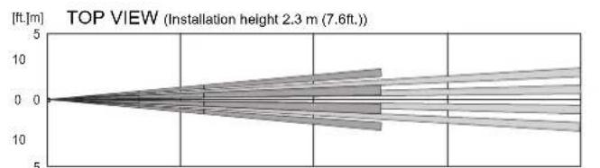
![| Distance [m] | Height [ft.] | | ------------ | ------------ | | 0 | 7.6 | | 1 | 2.3 | | 2 | 0 | | 3 | 0 | | 4 | 0 | | 5 | 0 | | 6 | 0 | | 7 | 0 | | 8 | 0 | | 9 | 0 | | 10 | 0 | | 20 | 0 | | 30 | 0 | | 40 | 0 | | 50 | 0 | | 60 | 0 | | 70 | 0 | | 80 | 0 | | 90 | 0 | | 100 | 0 | | 110 | 0 | | 120 | 0…](/content/2026/05/1008244/images/038785200c8f04aaeefa59bdb9e0af66a518d5ced2d915b036ac654c631cd498.jpg)
7 Masking the Far Area Sensor

Applicable
models
SIP-3020 SIP-4010 SIP-404 SIP-3020CAM DN
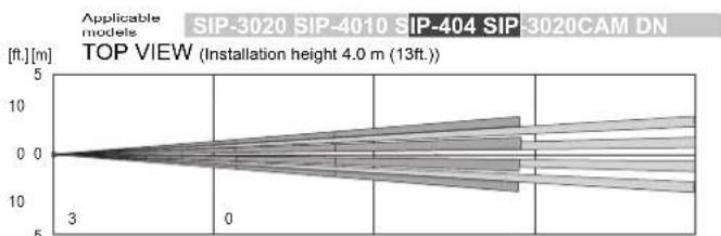
TOP VIEW (Installation height 4.0 m (13ft.))
The far area mirror mounted in the main unit has 2 far masking plates; one at the right side of this mirror and the other at the left side of this mirror. You can mask the detection area by changing the position of these masking plates.
Cautions>>
- You can only mask the detection area from its outside to its inside using the masking plates. You cannot mask only the inside detection area.
• However, if you need to mask the inside detection area only, use the white space (margin) of the near area masking seal (an accessory) for the masking. Attach the seal and mask all mirrors that you need to shield.
Cautions>>
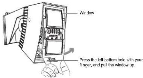
- The window is linked to the main unit by nylon wire loop so that the window does not fall. Do not pull the window using excessive force.
- After you have masked the detection areas, mount the window and place the excessive nylon wire loop inside the main unit.
How to remove the window>>
Applicable
models
SIP-3020 SIP-4010 SIP-404 SIP-3020CAM DN
① Remove the masking plate from the storage, and check the detection area and the mirror you use by referring to the area chart

② Attach the masking plate to the mirror, and secure it to the ribs.


Applicable
SIP-3020 SIP-4010 SIP-404 SIP-3020CAM DN
①
Remove the masking plate from the storage, and check the detection area and the mirror you use by referring to the area chart.
Far area mirror

②
Attach the masking plate to the mirror, and secure it to the ribs.

③
Insert the fixing rubber form to secure the knob of the masking plate.

8
MASKING THE NEAR AREA SENSOR
8-1
Masking the Detection Areas using Masking Plates
The near area mirror mounted in the main unit has 2 near masking plates; one at the right side of this mirror and another at the left side of this mirror. You can mask the detection area by changing the position of these masking plates.
Cautions>>
You can mask the outside detection areas only; they are areas 1 and 6. Use the area masking seals (an accessory) to mask the other detection areas (see Step 8-2).
Applicable
SIP-3020 SIP-4010 SIP-404 SIP-3020CAM DN
①
Remove the masking plate from the storage, and check the detection area and the mirror you use by referring to the area chart.
②
Attach the masking plate to the mirror, and secure it to the ribs.

Near area mirror

③
Insert the fixing rubber form to secure the knob of the masking plate.
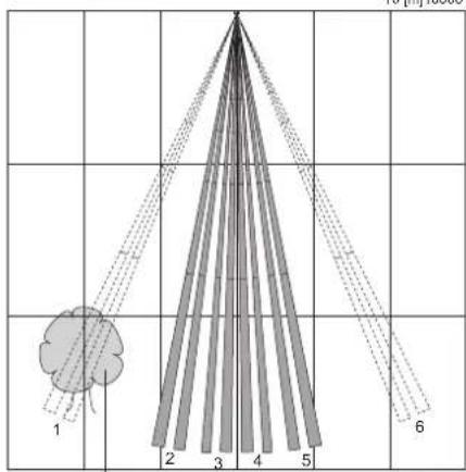
If tree branches or other moving objects are in the path of the detection beam.
[ft.]30 20 10 0 10 20 30 40 5050 40
10 [m]155051015
8-2 Masking the Detection Areas using Masking Seals
Using the tweezers (an accessory), carefully attach the area masking seals (an accessory) to the near area mirror.
![Near area mirror Area masking seals MIRROR F F⑥ F④ F② F F③F ① E E⑥ E④ E② E E③E ① D D⑥ D④ D② D D③D ① C C⑤ C④ C② C C③C ① B B⑥ B④ B② B B③B ① 50 [m]1015 15 10 5 0 10 20 30 40 C B 1 2 3 4 5 6 t [m] 3 4 0 2 0 10 20 30 40 50 60 70 80 90 100 [ft]](/content/2026/05/1008244/images/8786952e121b12ffafb8f070544e4499eb5511729d39a1473aac742a90ef5d58.jpg)
Points>>
If you are using the SIP-3020, SIP-4010, or SIP-404 sensor unit when you have completed Step 8, proceed to Step 9-2.
9 ADJUSTMENT OF CAMERA
9-1 Adjustment of Camera
Applicable models
SIP-3020 SIP-4010 SIP-404 SIP-3020CAM DN
(1) Open the camera cover, and connect the monitor unit cable to the camera unit.

(2) Adjust the vertical angle and the angle of view of the camera.
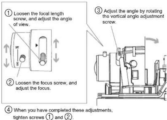
Cautions>>
The vertical camera angle adjustment mechanism is separated from the detection area control mechanism. To satisfy the BS8418 Standard, make sure that the vertical angle and the angle of view of the camera match the detection area correctly.
(3) Close the camera cover, and tighten two fixing screws.
(4) Check the image viewed by the camera, using the monitor unit or another monitoring device.
10 OPERATION TEST
9-2 Termination Procedure
Applicable
models
SIP-3020 SIP-4010 SIP-404 SIP-3020CAM DN
(1) After you have adjusted all sensor items, securely tighten all adjustment screws that you have loosened. Finally, securely tighten the bottom fixing screws.

Cautions>>
- If you need to adjust the detection area again, be sure to loosen the fi xing screw. If you try to move the main unit without loosening the fi xing screw, the unit may be damaged.
- When you mount the cover, place the excessive nylon wire loop in the main unit. If the wire has been pinched by the window and the cover, rain drops may be able to enter into the main unit.
(2) Mount the cover.
10-1 If There is a Public Street Where a People Walk or Cars Drive by the Detection Area
Points>>
Reduce the size of the detection area so that it does not include any public streets.
(1) Check to see that the arrow of the main unit is within the width of "Angle adjustment guide" on the adjustment screw.
(2) Using the area viewfinder, check to see that the detection area does not include any public streets.
(3) If the detection area does go beyond a public street, correct the vertical angle of the main unit. However, exercise care so that the arrow does not move away significantly from the "Angle adjustment guide" position.
If the arrow does move away significantly from the "Angle adjustment guide" position:
Mask the far area detection area using the masking plate or by using the far area masking switch. You may be required to also mask the near area detection area under specific sensor installation conditions (see Steps 5 and 8).
(4) When a person walks along the street or a car drives along it, check the detection area using the walk tester.
Points>>
You cannot mount and use both the area viewfinder and walk tester simultaneously.
Cautions>>
The detection area may increase if there is a large difference in temperature between the moving object and the background.

Cautions>>
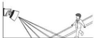
A heat source beyond the detection area may cause a false alarm due to the reflection of heat off the ground. Examples of types of surfaces that reflect include water (puddles), wet roads, smooth concrete surfaces and asphalt roads.
If the source of the heat is strong and/or the reflection rate is high, the detection distance will be longer than required and may detect unnecessary objects beyond the target area. Therefore, select the detection range position according to the ground conditions of the installation site.
10-2 If Tree Branches or Grass are Detected When They Move Within the Detection Area
Points>>
Adjust the detection area so that it does not cover tree branches or grass that move when the wind blows.
(1) Check to see that the arrow of the main unit is within the width of "Angle adjustment guide" on the adjustment screw.
(2) Using the area viewfinder, check to see that the detection area does not cover tree branches or grass that may move when the wind blows.
(3) Use the walk tester to listen for sound level changes when there is no apparent activity in the detection area. Adjust the detection area so that it does not detect unwanted areas.

If the sound level changes, some part of the detection area must be active (i.e.: an object is moving).
(4) Use the walk tester and locate the part of the detection area that is active. Change the walk tester selector switch position and determine whether the active part of the detection area is far or near.
(5) Using the area viewfinder again, locate the active detection area.
(6) Mask the active detection area. To do this, mask the area using the masking plate or the masking seal. Otherwise mask the area using the far area masking switch (see Steps 5, 7, and 8).
(7) Using the walk tester again, check that the sound level changes. If the sound level does not change excessively, you can finish the adjustment.
Points>>
You cannot mount and use both the area viewfinder and the walk tester simultaneously.
11 LED FUNCTIONS
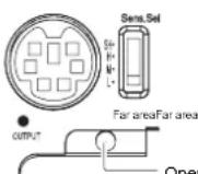
Cautions>>
If the red LED keeps blinking for approx. 60 seconds after turning the power on, turn the power off and then on again.
Operation indicator - Red LED
| DETECTOR STATUS If the cover is removed | |
| During power ON Blinks. | |
| During standby Turns OFF. | |
| When detected (in far/near area) Lights. | |
12 SPECIFICATIONS
12-1 Specifications of the Main Unit
Applicable models
SIP-3020 SIP-4010 SIP-404 SIP-3020CAM DN
| Model SIP-30 | 20 SIP-40 | 10 SIP-40 | 4 | SIP-3020 CAM DN |
| Detection method | Passive infrared | |||
| Coverage | 30 x 20m (100 x 65ft.) | 40 x 10m (130 x 33ft.) | 40 x 4m (130 x 13ft.) | 30 x 20m (100 x 65ft.) |
| Number of detection zones | 74 zones | 48 zones | 24 zones | 74 zones |
| Mounting height | 2.3 to 4m (7.6 to 13ft.) | |||
| Power input | 11 - 16V DC22 - 26V AC | 12V DC | ||
| With optional heating unit | 22 - 26V AC | Can not use SIP-HU | ||
| Current draw | 35mA max. (12V DC)70mA max. (24V AC) | 180mA max. (12V DC) | ||
| With optional heating unit | 410mA max. (24V AC) | — | ||
| Operation indicator | RED ALARM | |||
| Warm-up period | Approx. 60 sec. | |||
| Detection range selector | Far area: ON / OFF | |||
| Alarm interval period | 0 / 15 / 30 / 60 sec. | |||
| Detection logic selector | AND/OR | |||
| Tamper output | N.C. 28V DC, 0.1A max. | |||
| Trouble output | N.C. 28V DC, 0.2A max. | |||
| Alarm output | N.C.28V DC, 0.2A max.N.O.28V DC, 0.2A max. | |||
| Sensitivity selector | Far: SH/H/M/L Near: SH/H/M/L | |||
| Operating temperature | -25 to +60°C, -40 to +60°C with optional heating unit (-13 to +140°F, -40 to +140°F with optional heating unit) | |||
| IP rating | Main unit: IP65 Chassis :IP55 | |||
| Dimensions (H × W × D) | 227 x 102 x 266mm(9.0 x 4.0 x 10.5 in.) | 252 x 102 x 317 mm(9.9 x 4.0 x 12.5 in.) | ||
| Weight | 1.2kg (42 oz.) | 1.5kg (52 oz.) | ||
| Accessories | Screws, paper template, allen key, area masking seal, tweezers, instruction manual, area plate, fixing rubber form | |||
12-2
Camera Specifications
Applicable models
SIP-3020 SIP-4010 SIP-404 SIP-3020CAM DN
| Model | SIP-3020CAM DN (EU) S | IP-3020CAM DN (US) |
| Image sensor 1/3" | CCD (PAL) 1/3" C | CD (NTSC) |
| TV line 480TVL | (at wide position) | |
| Resolution PAL | 752 H x 582 V | NTSC768 H x 494 V |
| Lens | f = 3 to 9mm, varifocal, DC auto iris lens F1.2 | |
| Minimum illumination Day (colour): 0.5 lx (F1.2)Night (B/W): 0.03 lx (F1.2) | ||
| Video output | 1.0Vp-p/75 Ω/BNC connector, PAL | 1.0Vp-p/75 Ω /BNCconnector, NTSC |
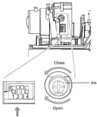
| DIP switch No. | NAME Function Factory default | setting | |
| 1 ELC | /ALC Exposure control method setting | OFF (ALC) | |
| 2 | AGC | Automatic sensitivity setting | ON |
| 3 | BLC | Backlight correction | ON |
| 4 | * Leave this switch OFF (factory default). | ||
DIMENSION
SIP-3020/4010/404
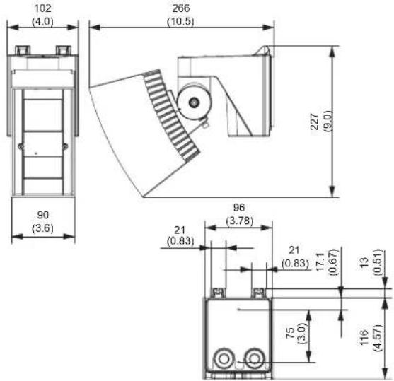
Unit:mm (inch)
SIP-3020CAM
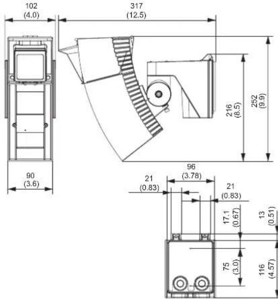
Unit:mm (inch)
OPTION
• OPM-WT, AWT-3 -Audio Walk Tester
• AVF-1 -Area View Finder
- SIP-MINIHOOD -Sun/Snow shield
- SIP-HU -Heating unit
Cautions>>
When SIP-HU is used, the power for SIP unit should be 22 - 26V AC.
SIP-3020CAM DN can not use SIP-HU.
These units are designed to detect movement to activate CCTV system. Being only part of a complete surveillance system, we cannot accept responsibility for any damage or other consequences resulting from the activation of the unit. This product confirms the EMC Directive 2004/108/EC.
Specifications and design are subject to change without prior notice.

OPTEX
OPTEX CO., LTD. (JAPAN)
(ISO 9001 Certified) (ISO 14001 Certified)
5-8-12 Ogoto Otsu Shiga 520-0101 JAPAN
TEL:+81-77-579-8670 FAX:+81-77-579-8190
URL:http://www.optex.co.jp/e/
OPTEX INCORPORATED (USA)
TEL:+1-909-993-5770
Tech:(800)966-7839
URL:http://www.optexamerica.com/
OPTEX (EUROPE) LTD. (UK)
TEL:+44-1628-631000
URL:http://www.optexeurope.com/
OPTEX SECURITY SAS (FRANCE)
TEL:+33-437-55-50-50
URL:http://www.optex-security.com/
OPTEX SECURITY Sp. z o. o.
(POLAND)
TEL:+48-22-598-06-55
URL:http://www.optex.com.pl/


- FEATURES
- 1 PARTS IDENTIFICATION
- 2 INSTALLATION AND MAINTENANCE NOTES
- INSTALLATION HINTS
- 3 INSTALLATION AND ANGLE ADJUSTMENT
- WALL MOUNTING
- CAUTIONS
- CAUTION
- INSIDE VIEW OF THE BASE
- WIRING
- 4
- DETECTION AREA SETTING
- MOUNTING TIPS
- ADJUSTING TIPS
- IF IT IS DIFFICULT TO DETECT AN OBJECT
- 5 FUNCTION SETTING
- SENSITIVITY SELECTOR SWITCH FOR NEAR AND FAR AREA
- SIP-3020 SIP-4010 SIP-404 SIP-3020CAM DN
- DETECTION LOGIC SELECTOR SWITCH
- DETECTION RANGE SELECTOR SWITCH
- ALARM INTERVAL SWITCH
- 7 MASKING THE FAR AREA SENSOR
- 8
- MASKING THE NEAR AREA SENSOR
- 8-1
- MASKING THE DETECTION AREAS USING MASKING PLATES
- MASKING THE DETECTION AREAS USING MASKING SEALS
- POINTS
- 9 ADJUSTMENT OF CAMERA
- ADJUSTMENT OF CAMERA
- 10 OPERATION TEST
- TERMINATION PROCEDURE
- IF THERE IS A PUBLIC STREET WHERE A PEOPLE WALK OR CARS DRIVE BY THE DETECTION AREA
- IF TREE BRANCHES OR GRASS ARE DETECTED WHEN THEY MOVE WITHIN THE DETECTION AREA
- 11 LED FUNCTIONS
- 12 SPECIFICATIONS
- SPECIFICATIONS OF THE MAIN UNIT
- 12-2
- CAMERA SPECIFICATIONS
- DIMENSION
- OPTION
- OPTEX
- OPTEX CO., LTD. (JAPAN)
- OPTEX INCORPORATED (USA)
- OPTEX (EUROPE) LTD. (UK)
- OPTEX SECURITY SAS (FRANCE)
- OPTEX SECURITY SP. Z O. O
- (POLAND)
Brand : OPTEX
Model : Redwall SIP-3020-IP-BOX
Category : Motion detector