
SG6428X - Network switch TP-LINK - Free user manual and instructions
Find the device manual for free SG6428X TP-LINK in PDF.


| Product Type | Managed Gigabit Switch (L2/L3) |
| Ports | 24 Gigabit Ethernet ports + 4 SFP+ 10G slots |
| Dimensions (W x D x H) | 440 x 220 x 44 mm (1U) |
| Weight | Approx. 3.0 kg |
| Power Supply | Internal 100-240V AC, 50/60 Hz |
| Management Interfaces | Web GUI (HTTP/HTTPS), CLI (Console, SSH, Telnet), SNMP |
| Layer 2 Features | VLAN (802.1Q, MAC, Protocol, Private), STP/RSTP/MSTP, LACP, IGMP/MLD Snooping, MVR, GVRP, LLDP |
| Layer 3 Features | Static Routing, RIP, OSPF, DHCP Server/Relay, ARP, VRRP (on select models) |
| Security Features | 802.1X, ACL (MAC, IP, IPv6, Combined), Port Security, DoS Defend, DHCP Filter, IP-MAC Binding |
| QoS | 802.1p/DSCP priority, Rate Limit, Storm Control, Voice VLAN, Auto VoIP |
| PoE | Not supported on this model (SG6428X is non-PoE) |
| Stacking | Supported (up to 4 units) |
| System Monitoring | sFlow (on select), Mirroring, RMON, Syslog, CPU/Memory monitoring |
| Standards | IEEE 802.3, 802.3u, 802.3ab, 802.3ae, 802.3x, 802.1q, 802.1p, etc. |
| Cleaning Instructions | Disconnect power, use a dry soft cloth to clean the case. Do not use liquid or aerosol cleaners. |
| Safety Warnings | Use only the supplied power adapter. Do not open the device. Keep away from water and humidity. |
| Spare Parts / Repairability | No user-serviceable parts. Contact TP-Link support for repairs. |
| General Information | Brand: TP-Link; Model: SG6428X; Category: Network Switch; User manual available in PDF (999 pages) |
Frequently Asked Questions - SG6428X TP-LINK
erase startup-config then reload. This will restore all settings to factory defaults.vlan 10 then interface gigabitEthernet 1/0/1 and switchport access vlan 10.User questions about SG6428X TP-LINK
0 question about this device. Answer the ones you know or ask your own.
Ask a new question about this device
Download the instructions for your Network switch in PDF format for free! Find your manual SG6428X - TP-LINK and take your electronic device back in hand. On this page are published all the documents necessary for the use of your device. SG6428X by TP-LINK.
USER MANUAL SG6428X TP-LINK
Accessing the Switch
Determine the Management Method 4
Web Interface Access....5
Login....5
Save the Configuration File....6
Disable the Web Server 7
Configure the Switch's IP Address and Default Gateway 8
Command Line Interface Access 10
Console Login (only for switch with console port)....10
SSH Login....12
Telnet Login....16
Disable SSH login 17
Disable Telnet login....18
Copy running-config startup-config....18
Change the Switch's IP Address and Default Gateway....19
Managing System
System 21
Overview....21
Supported Features....21
System Info Configurations 23
Using the GUI 23
Viewing the System Summary....23
Configuring the Device Description....27
Configuring the System Time 27
Configuring the Daylight Saving Time....28
Configuring LED (Only for Certain Devices)....29
Using the CLI 30
Viewing the System Summary....30
Configuring the Device Description....31
Configuring the System Time 32
Configuring the Daylight Saving Time....35
Configuring LED (Only for Certain Devices) 37
User Management Configurations.... 38
Using the GUI 38
Creating Accounts 38
Configuring Enable Password....39
Using the CLI 40
Creating Accounts 40
Configuring Enable Password....41
System Tools Configurations 44
Using the GUI 44
Configuring the Boot File 44
Restoring the Configuration of the Switch 46
Backing up the Configuration File....46
Upgrading the Firmware....47
Configuring DHCP Auto Install (Only for Certain Devices)....47
Rebooting the switch....49
Resetting the Switch....50
Using the CLI....51
Configuring the Boot File....51
Restoring the Configuration of the Switch 52
Backing up the Configuration File....52
Upgrading the Firmware....53
Upgrading the MCU-Firmware....54
Configuring DHCP Auto Install (Only for Certain Devices) 54
Rebooting the Switch 55
Resetting the Switch....57
EEE Configuration....58
Using the CLI....58
PoE Configurations (Only for Certain Devices) 60
Using the GUI 61
Configuring the PoE Parameters Manually....61
Configuring the PoE Parameters Using the Profile....64
Configuring the PoE Auto Recovery Parameters Manually....67
Using the CLI....69
Configuring the PoE Parameters Manually....69
Configuring the PoE Parameters Using the Profile....71
Management Port Configurations (Only for Certain Devices)....74
Using the CLI....74
Power Supply Configurations (Only for Certain Devices)....76
Using the CLI....76
Configuring the Power Backup Mode....76
SDM Template Configuration....77
Using the GUI 77
Using the CLI....78
Time Range Configuration....80
Using the GUI 80
Adding Time Range Entries....80
Configuring Holiday 82
Using the CLI....83
Adding Time Range Entries....83
Configuring Holiday 84
Controller Settings (Only for Certain Devices) 86
Using the GUI....86
Enabling Cloud-Based Controller Management....86
Configuring Controller Inform URL....87
Using the CLI 87
Enabling Cloud-Based Controller Management....87
Configuring Controller Inform URL....87
File System Configurations....89
Using the CLI 89
Configuring the File System....89
FTP, SFTP and SCP Configurations 91
Using the CLI....91
Using the FTP 91
Using the SFTP....92
Using the SCP....92
Example for PoE Configurations....93
Network Requirements....93
Configuring Scheme....93
Using the GUI....93
Using the CLI 96
Appendix: Default Parameters....98
Managing Physical Interfaces
Physical Interface 102
Overview 102
Supported Features 102
Basic Parameters Configurations 103
Using the GUI 103
Using the CLI 104
Port Isolation Configurations 107
Using the GUI 107
Using the CLI 108
Loopback Detection Configuration 110
Using the GUI 110
Using the CLI 112
Configuration Examples 114
Example for Port Isolation 114
Network Requirements 114
Configuration Scheme 114
Using the GUI....114
Using the CLI 116
Example for Loopback Detection....117
Network Requirements....117
Configuration Scheme....117
Using the GUI....118
Using the CLI 119
Appendix: Default Parameters....120
Configuring Stack
Overview 122
Stack Concepts....123
Stack Operation Procedure 125
Stack Topology....127
Stack Operation Procedure 129
Using the GUI 129
Viewing the Stack Information....129
Configuring the Provision Info 130
Configuring the Provisioned Member 131
Configuring the Stack Member....131
Configuring the Stack Port Group 132
Using the CLI....136
Configuring Stack System Name....136
Entering Stack Port Group View 136
Configuring Stack Port....136
Viewing Current Stack Port Group Info....137
Configuring Stack Device Priority....137
Modifying Stack Unit ID....138
Configuring Provision Entries....138
Viewing Stack Info 139
Appendix: Default Parameters....140
Configuring DDM (Only for Certain Devices)
Overview 142
DDM Configuration....143
Using the GUI 143
Configuring DDM Globally....143
Configuring the Threshold....144
Viewing DDM Status....149
Using the CLI 149
Configuring DDM Globally....149
Configuring DDM Shutdown....150
Configuring the Threshold....151
Viewing DDM Configuration....157
Viewing DDM Status....158
Appendix: Default Parameters....159
Configuring LAG
LAG....161
Overview....161
Supported Features....161
LAG Configuration....162
Using the GUI 163
Configuring Load-balancing Algorithm....163
Configuring Static LAG or LACP....164
Using the CLI....166
Configuring Load-balancing Algorithm....166
Configuring Static LAG or LACP....168
Configuration Examples....172
Example for Static LAG 172
Network Requirements....172
Configuration Scheme....172
Using the GUI....172
Using the CLI 173
Example for LACP 174
Network Requirements....174
Configuration Scheme....174
Using the GUI....175
Using the CLI 176
Appendix: Default Parameters....179
Managing MAC Address Table
MAC Address Table....181
Overview....181
Supported Features....181
MAC Address Configurations....183
Using the GUI 183
Adding Static MAC Address Entries 183
Modifying the Aging Time of Dynamic Address Entries....185
Adding MAC Filtering Address Entries....185
Viewing Address Table Entries....186
Using the CLI 186
Adding Static MAC Address Entries 186
Modifying the Aging Time of Dynamic Address Entries....188
Adding MAC Filtering Address Entries....188
Security Configurations 190
Using the GUI 191
Configuring MAC Notification Traps 191
Limiting the Number of MAC Addresses Learned in VLANs....192
Using the CLI....194
Configuring MAC Notification Traps....194
Limiting the Number of MAC Addresses in VLANs 196
Example for Security Configurations....198
Network Requirements....198
Configuration Scheme 198
Using the GUI 199
Using the CLI 200
Appendix: Default Parameters....201
Configuring 802.1Q VLAN
Overview 203
802.1Q VLAN Configuration....204
Using the GUI 204
Configuring the VLAN....204
Configuring Port Parameters for 802.1Q VLAN 205
Using the CLI....206
Creating a VLAN 206
Adding the Port to the Specified VLAN....207
Configuring the Port 208
Configuration Example 210
Network Requirements....210
Configuration Scheme 210
Network Topology....211
Using the GUI 211
Using the CLI 214
Appendix: Default Parameters ....216
Configuring MAC VLAN
Overview 218
MAC VLAN Configuration....219
Using the GUI 219
Configuring 802.1Q VLAN 219
Binding the MAC Address to the VLAN....219
Enabling MAC VLAN for the Port....220
Using the CLI 221
Configuring 802.1Q VLAN 221
Binding the MAC Address to the VLAN....221
Enabling MAC VLAN for the Port....222
Configuration Example 223
Network Requirements....223
Configuration Scheme 223
Using the GUI 224
Using the CLI 227
Appendix: Default Parameters....230
Configuring Protocol VLAN
Overview 232
Protocol VLAN Configuration....233
Using the GUI 233
Configuring 802.1Q VLAN 233
Creating Protocol Template 234
Configuring Protocol VLAN....235
Using the CLI 236
Configuring 802.1Q VLAN 236
Creating a Protocol Template....236
Configuring Protocol VLAN....237
Configuration Example 240
Network Requirements....240
Configuration Scheme 240
Using the GUI 241
Using the CLI 246
Appendix: Default Parameters....250
Configuring VLAN-VPN (Only for Certain Devices)
VLAN-VPN 252
Overview....252
Supported Features....253
Basic VLAN-VPN Configuration 254
Using the GUI 254
Configuring 802.1Q VLAN 254
Configuring Basic VLAN-VPN 255
Using the CLI 256
Configuring 802.1Q VLAN 256
Configuring Basic VLAN-VPN 256
Flexible VLAN-VPN Configuration....259
Using the GUI 259
Using the CLI....260
Configuration Examples....262
Example for Basic VLAN VPN 262
Network Requirements......262
Configuration Scheme....262
Using the GUI....263
Using the CLI 268
Example for Flexible VLAN VPN 272
Network Requirements....272
Configuration Scheme....272
Using the GUI....273
Using the CLI 280
Appendix: Default Parameters....283
Configuring GVRP
Overview 285
GVRP Configuration....286
Using the GUI 287
Using the CLI 288
Configuration Example 291
Network Requirements....291
Configuration Scheme 291
Using the GUI 292
Using the CLI 296
Appendix: Default Parameters....300
Configuring Private VLAN (Only for Certain Devices)
Overview 302
Private VLAN Configurations ....304
Using the GUI 304
Using the CLI 305
Creating Private VLAN....305
Configuring the Up-link Port 307
Configuring the Down-link Port....309
Configuration Example 311
Network Requirements....311
Configuration Scheme 311
Network Topology....311
Using the GUI 312
Using the CLI
Appendix: Default Parameters
Configuring Multicast
Layer 2 Multicast
Overview
Supported Features
IGMP Snooping Configuration
Using the GUI
Configuring IGMP Snooping Globally
Configuring IGMP Snooping for VLANs
Configuring IGMP Snooping for Ports
Configuring Hosts to Statically Join a Group
Configuring IGMP Accounting and Authentication Features
Using the CLI
Configuring IGMP Snooping Globally
Configuring IGMP Snooping for VLANs 334
Configuring IGMP Snooping for Ports....339
Configuring Hosts to Statically Join a Group....340
Configuring IGMP Accounting and Authentication Features....341
MLD Snooping Configuration....345
Using the GUI 345
Configuring MLD Snooping Globally 345
Configuring MLD Snooping for VLANs....346
Configuring MLD Snooping for Ports 349
Configuring Hosts to Statically Join a Group 349
Using the CLI 350
Configuring MLD Snooping Globally 350
Configuring MLD Snooping for VLANs....351
Configuring MLD Snooping for Ports 356
Configuring Hosts to Statically Join a Group....357
MVR Configuration 359
Using the GUI 359
Configuring 802.1Q VLANs....359
Configuring MVR Globally....360
Adding Multicast Groups to MVR....361
Configuring MVR for the Port....362
(Optional) Adding Ports to MVR Groups Statically 363
Using the CLI 364
Configuring 802.1Q VLANs....364
Configuring MVR Globally....364
Configuring MVR for the Ports 366
Multicast Filtering Configuration....369
Using the GUI 369
Creating the Multicast Profile....369
Configure Multicast Filtering for Ports 371
Using the CLI 372
Creating the Multicast Profile....372
Binding the Profile to Ports 375
Viewing Multicast Snooping Information....379
Using the GUI 379
Viewing IPv4 Multicast Table....379
Viewing IPv4 Multicast Statistics on Each Port 380
Viewing IPv6 Multicast Table....381
Viewing IPv6 Multicast Statistics on Each Port 382
Using the CLI 383
Viewing IPv4 Multicast Snooping Information....383
Viewing IPv6 Multicast Snooping Configurations....384
PIM Configuration....385
Using the CLI 385
Configuring IP Multicast-routing Globally....385
Configuring IP PIM Globally 385
Configuring IP PIM On Specified Port 386
Configuring IP PIM Hello-Interval....387
Viewing IP Multicast Info 387
Viewing IP Mroute 388
Viewing IP PIM Interface Info 388
Viewing IP PIM Neighbor Info 389
Viewing IP PIM Statistic 390
Static Multicast-Routing Configuration....391
Using the CLI 391
Configuring Static Multicast-routing Entries....391
Viewing IP Mroute Static Info 391
Layer 3 IGMP Configuration....393
Using the CLI....393
Configuring IP IGMP Globally....393
Configuring IP IGMP On Ports....393
Configuration Examples....398
Example for Configuring Basic IGMP Snooping....398
Network Requirements....398
Configuration Scheme....398
Using the GUI....399
Using the CLI 401
Example for Configuring MVR 403
Network Requirements....403
Network Topology....403
Configuration Scheme....404
Using the GUI....404
Using the CLI 407
Example for Configuring Unknown Multicast and Fast Leave....410
Network Requirement....410
Configuration Scheme....411
Using the GUI....411
Using the CLI 413
Example for Configuring Multicast Filtering....414
Network Requirements....414
Configuration Scheme....414
Network Topology....414
Using the GUI....415
Using the CLI 419
Appendix: Default Parameters ....422
Default Parameters for IGMP Snooping 422
Default Parameters for MLD Snooping....423
Default Parameters for MVR....424
Default Parameters for Multicast Filtering....424
Default Parameters for PIM....424
Default Parameters for Static Multicast-Routing....425
Default Parameters for Layer 3 IGMP....425
Configuring Spanning Tree
Spanning Tree....427
Overview 427
Basic Concepts 427
STP/RSTP Concepts....427
MSTP Concepts 431
STP Security 432
STP/RSTP Configurations 435
Using the GUI 435
Configuring STP/RSTP Parameters on Ports....435
Configuring STP/RSTP Globally....437
Verifying the STP/RSTP Configurations....439
Using the CLI 441
Configuring STP/RSTP Parameters on Ports....441
Configuring Global STP/RSTP Parameters 443
Enabling STP/RSTP Globally....444
MSTP Configurations 447
Using the GUI 447
Configuring Parameters on Ports in CIST 447
Configuring the MSTP Region 450
Configuring MSTP Globally....454
Verifying the MSTP Configurations 456
Using the CLI 457
Configuring Parameters on Ports in CIST 457
Configuring the MSTP Region 460
Configuring Global MSTP Parameters....463
Enabling Spanning Tree Globally....465
STP Security Configurations....467
Using the GUI 467
Using the CLI 468
Configuring the STP Security 468
Configuration Example for MSTP 471
Network Requirements......471
Configuration Scheme 471
Using the GUI 472
Using the CLI 478
Appendix: Default Parameters....485
Configuring LLDP
LLDP 488
Overview....488
Supported Features....488
LLDP Configurations 489
Using the GUI 489
Configuring LLDP Globally....489
Configuring LLDP For the Port 491
Using the CLI....492
Global Config....492
Port Config....494
LLDP-MED Configurations....497
Using the GUI 497
Configuring LLDP Globally 497
Configuring LLDP-MED Globally 497
Configuring LLDP-MED for Ports....498
Using the CLI 500
Global Config....500
Port Config....501
Viewing LLDP Settings....504
Using GUI....504
Viewing LLDP Device Info 504
Viewing LLDP Statistics 508
Using CLI 509
Viewing LLDP-MED Settings 510
Using GUI....510
Using CLI 513
Configuration Example 514
Configuration Example for LLDP....514
Network Requirements....514
Network Topology....514
Configuration Scheme....514
Using the GUI....514
Using CLI....515
Example for LLDP-MED 521
Network Requirements....521
Configuration Scheme....521
Using the GUI....521
Using CLI....524
Appendix: Default Parameters....527
Configuring L2PT (Only for Certain Devices)
Overview 529
L2PT Configuration....531
Using the GUI 531
Using the CLI....532
Configuration Example 536
Network Requirements....536
Configuration Scheme 536
Using the GUI 536
Using the CLI....537
Appendix: Default Parameters....539
Configuring PPPoE ID Insertion (Only for Certain Devices)
Overview 541
PPPoE ID Insertion Configuration....542
Using the GUI 542
Using the CLI....543
Appendix: Default Parameters....546
Configuring Layer 3 Interfaces
Overview 548
Layer 3 Interface Configurations....549
Using the GUI 549
Creating a Layer 3 Interface....549
Configuring IPv4 Parameters of the Interface 551
Configuring IPv6 Parameters of the Interface 552
Viewing Detail Information of the Interface 555
Using the CLI 556
Creating a Layer 3 Interface....556
Configuring IPv4 Parameters of the Interface 558
Configuring IPv6 Parameters of the Interface 559
Configuration Example 562
Network Requirement....562
Configuration Scheme 562
Using the GUI 562
Using the CLI 563
Appendix: Default Parameters....565
Configuring Routing
Overview 567
IPv4 Static Routing Configuration 568
Using the GUI 568
Using the CLI 569
IPv6 Static Routing Configuration....570
Using the GUI 570
Using the CLI....570
Viewing Routing Table 572
Using the GUI 572
Viewing IPv4 Routing Table....572
Viewing IPv6 Routing Table....573
Using the CLI 573
Viewing IPv4 Routing Table....573
Viewing IPv6 Routing Table....574
RIP Configurations....575
Using the CLI 575
Enabling RIP Function....575
Enabling RIP Function for Specific Network Segment....575
Configuring RIP Message Version....576
Configuring RIP Timer....577
Configuring Management Distance 578
Enabling Auto-summary Function 579
Setting Default Metric 579
Configuring RIP Redirection 580
Enabling ECMP Function 581
Introducing Default Route 582
Configuring RIP Neighbor 582
Configuring Passive-Interface 583
Configuring Authentication Mode 584
Configuring Authentication String 585
Configuring Authentication Key-chain 585
Configuring Receive Version 586
Configuring Send Version 587
Configuring Split Horizon 588
Enabling RIPv2 Packet Broadcast 589
Viewing RIP Routing Table 589
Viewing IP Status 590
Clearing IP RIP 590
RIPng Configurations 592
Using the CLI 592
Enabling RIPng Function 592
Enabling RIP Function on Specific Port 592
Configuring RIPng Timer 593
Setting Default Metric 594
Configuring RIPng Redirection 595
Enabling ECMP Function 596
Introducing Default Route 597
Configuring Passive-Interface 597
Configuring Split Horizon 598
Viewing RIPng Routing Table 599
Viewing IPv6 Status 599
Clearing IPv6 RIP 600
OSPF Configurations....601
Using the CLI 601
Configuring Router OSPF....601
Configuring Router ID 602
Configuring Network....602
Configuring Max-Paths....603
Configuring ASBR....604
Configuring Default-Metric....605
Configuring Default-Information Originate....606
Configuring Auto-Cost....607
Configuring OSPF Administrative Distance....608
Configuring Computing Delay and Interval 609
Configuring RFC 1583 610
Defining Stub Area 611
Defining NSSA Area 612
Configuring Area Default-Cost 613
Configuring Summary Route 614
Configuring Area Authentication 616
Configuring Virtual-Link 616
Configuring Virtual-Link Authentication 617
Configuring Area Virtual-Link Simple Authentication Key 618
Configuring Area Virtual-Link Message-Digest-Key 619
Configuring Interface Cost 620
Configuring IP OSPF Retransmit-Interval....621
Configuring IP OSPF Transmit-Delay 622
Configuring IP OSPF Priority....623
Configuring IP OSPF Hello-Interval....624
Configuring IP OSPF Dead-Interval 624
Configuring IP OSPF Authentication....625
Configuring IP OSPF Authentication-Key 626
Configuring IP OSPF Message-Digest-Key....627
Configuring IP OSPF Network Type....628
Ignoring MTU Check....629
Preventing OSPF Packets....629
Resetting OSPF Process....630
Viewing OSPF Configuration Info....630
OSPFv3 Configurations....632
Using the CLI 632
Enabling OSPFv3 Routing 632
Configuring Router ID 632
Configuring Max-Paths....633
Configuring ASBR 634
Configuring Default-Information Originate....635
Configuring Auto-Cost....636
Configuring OSPFv3 Administrative Distance....636
Configuring OSPFv3 Distance....637
Configuring Computing Delay and Interval 638
Configuring OSPFv3 LSA Reception Interval....639
Defining Stub Area 639
Defining NSSA Area 640
Configuring Summary Route 641
Assigning Interfaces 642
Configuring Interface Cost 643
Configuring IPv6 OSPF Retransmit-Interval....644
Configuring IPv6 OSPF Transmit-Delay 645
Configuring IPv6 OSPF Priority 646
Configuring IPv6 OSPF Hello-Interval....647
Configuring IPv6 OSPF Dead-Interval....647
Configuring IPv6 OSPF Network Type 648
Ignoring MTU Check....649
Preventing OSPFv3 Packets 650
Resetting OSPFv3 Process....651
Viewing OSPFv3 Configuration Info 651
Example for Static Routing....652
Network Requirements....652
Configuration Scheme 652
Using the GUI 652
Using the CLI 654
Configuring DHCP Service
DHCP 659
Overview....659
Supported Features....659
DHCP Server Configuration....664
Using the GUI 664
Enabling DHCP Server 664
Configuring DHCP Server Pool 666
Configuring Manual Binding 667
Using the CLI 668
Enabling DHCP Server 668
Configuring DHCP Server Pool 671
Configuring Manual Binding 674
DHCP Relay Configuration 677
Using the GUI 677
Enabling DHCP Relay and Configuring Option 82 677
Configuring DHCP Interface Relay 679
Configuring DHCP VLAN Relay 679
Using the CLI 681
Enabling DHCP Relay 681
(Optional) Configuring Option 82 682
Configuring DHCP Interface Relay 684
Configuring DHCP VLAN Relay 685
DHCP L2 Relay Configuration....688
Using the GUI 688
Enabling DHCP L2 Relay 688
Configuring Option 82 for Ports....689
Using the CLI 690
Enabling DHCP L2 Relay 690
Configuring Option 82 for Ports....691
Configuration Examples....694
Example for DHCP Server....694
Network Requirements....694
Configuration Scheme....694
Using the GUI....694
Using the CLI 696
Example for DHCP Interface Relay 696
Network Requirements....696
Configuration Scheme....697
Using the GUI....698
Using the CLI 703
Example for DHCP VLAN Relay 706
Network Requirements....706
Configuration Scheme....706
Using the GUI....707
Using the CLI 710
Example for Option 82 in DHCP Relay....712
Network Requirements....712
Configuration Scheme....713
Configuring the DHCP Relay Switch....714
Configuring the DHCP Server 716
Example for DHCP L2 Relay 718
Network Requirements....718
Configuration Scheme....718
Configuring the DHCP Relay Switch....719
Configuring the DHCP Server 722
Appendix: Default Parameters....724
Configuring ARP
Overview 728
Supported Features....728
ARP Configurations....730
Using the GUI 730
Viewing the ARP Entries 730
Adding Static ARP Entries Manually....731
Configuring Gratuitous ARP 731 Configuring Proxy ARP....732 Configuring Local Proxy ARP 733
Using the CLI....734
Configuring the ARP Entry 734 Configuring the Gratuitous ARP 736 Configuring Proxy ARP 739
Appendix: Default Parameters....741
Configuring VRRP
Overview 743 VRRP Configuration....744
Using the CLI....744
Configuring VRRP on Specified Ports....744
Appendix: Default Parameters....749
Configuring QoS
QoS....751
Overview....751 Supported Features....751
Class of Service Configuration....753
Using the GUI 754
Configuring Port Priority....754 Configuring 802.1p Priority....756 Configuring DSCP Priority....759 Specifying the Scheduler Settings 762
Using CLI 765
Configuring Port Priority....765 Configuring 802.1p Priority 767 Configuring DSCP Priority....770 Specifying the Scheduler Settings 776
Bandwidth Control Configuration....780
Using the GUI 780
Configuring Rate Limit....780 Configuring Storm Control 781
Using the CLI....782
Configuring Rate Limit....782
Configuring Storm Control 784
Voice VLAN Configuration....786
Using the GUI 786
Configuring OUI Addresses 786
Configuring Voice VLAN Globally 788
Adding Ports to Voice VLAN 788
Using the CLI....789
Auto VoIP Configuration 792
Using the GUI....792
Using the CLI....793
Configuration Examples....797
Example for Class of Service....797
Network Requirements....797
Configuration Scheme....797
Using the GUI....798
Using the CLI 800
Example for Voice VLAN 802
Network Requirements....802
Configuration Scheme....803
Using the GUI....803
Using the CLI 807
Example for Auto VoIP 810
Network Requirements 810
Configuration Scheme....811
Using the GUI....811
Using the CLI 815
Appendix: Default Parameters....821
Configuring Access Security
Access Security 826
Overview 826
Supported Features 826
Access Security Configurations 827
Using the GUI 827
Configuring the Access Control Feature....827
Configuring the HTTP Function 830
Configuring the HTTPS Function....832
Configuring the SSH Feature 835
Configuring the Telnet Function....836
Configuring the Serial Port Parameters....837
Using the CLI 837
Configuring the Access Control Feature....837
Configuring the HTTP Function 839
Configuring the HTTPS Function....841
Configuring the SSH Feature 844
Configuring the Telnet Function....846
Configuring the Serial Port Parameters....846
Appendix: Default Parameters....848
Configuring AAA
Overview 851
AAA Configuration....852
Using the GUI 853
Adding Servers....853
Configuring Server Groups....855
Configuring the Method List....856
Configuring the AAA Application List 858
Configuring Login Account and Enable Password 858
Using the CLI 859
Adding Servers 859
Configuring Server Groups....862
Configuring the Method List....863
Configuring the AAA Application List....864
Configuring Login Account and Enable Password 868
Configuration Example 871
Network Requirements 871
Configuration Scheme 871
Using the GUI 872
Using the CLI 874
Appendix: Default Parameters....877
Configuring 802.1x
Overview 880
802.1x Configuration....881
Using the GUI 881
Configuring the RADIUS Server 881
Configuring 802.1x Globally....884
Configuring 802.1x on Ports....885
View the Authenticator State 887
Using the CLI 888
Configuring the RADIUS Server 888
Configuring 802.1x Globally....890
Configuring 802.1x on Ports....892
Viewing Authenticator State....894
Configuration Example 896
Network Requirements....896
Configuration Scheme 896
Network Topology....896
Using the GUI 897
Using the CLI 899
Appendix: Default Parameters....902
Configuring Port Security
Overview 904
Port Security Configuration....905
Using the GUI 905
Using the CLI 906
Appendix: Default Parameters....909
Configuring ACL
Overview 911
ACL Configuration....912
Using the GUI 912
Configuring Time Range 912
Creating an ACL....912
Configuring ACL Rules....913
Configuring MAC ACL Rule....913
Configuring IP ACL Rule....918
Configuring Combined ACL Rule....922
Configuring the IPv6 ACL Rule....927
Configuring the Packet Content ACL Rule....931
Configuring ACL Binding....936
Using the CLI 937
Configuring Time Range 937
Configuring ACL 937
Configuring Policy....947
Configuring ACL Binding....949
Viewing ACL Counting 950
Configuration Example for ACL....951
Configuration Example for MAC ACL....951
Network Requirements 951
Configuration Scheme....951
Using the GUI....952
Using the CLI 958
Configuration Example for IP ACL....959
Network Requirements....959
Configuration Scheme....960
Using the GUI....960
Using the CLI 966
Configuration Example for Combined ACL....968
Network Requirements....968
Configuration Scheme....968
Using the GUI....969
Using the CLI 974
Appendix: Default Parameters....976
Configuring IPv4 IMPB
IPv4 IMPB 979
Overview 979
Supported Features....979
IP-MAC Binding Configuration....980
Using the GUI 980
Binding Entries Manually 980
Binding Entries via ARP Scanning....981
Binding Entries via DHCP Snooping....983
Viewing the Binding Entries....985
Using the CLI....986
Binding Entries Manually....986
Binding Entries via DHCP Snooping....988
Viewing Binding Entries 989
ARP Detection Configuration....990
Using the GUI 990
Adding IP-MAC Binding Entries 990
Enabling ARP Detection....990
Configuring ARP Detection on Ports 991
Viewing ARP Statistics....992
Using the CLI....993
Adding IP-MAC Binding Entries 993
Enabling ARP Detection....993
Configuring ARP Detection on Ports 994
Viewing ARP Statistics....996
IPv4 Source Guard Configuration....997
Using the GUI 997
Adding IP-MAC Binding Entries 997
Configuring IPv4 Source Guard 997
Using the CLI 998
Adding IP-MAC Binding Entries 998
Configuring IPv4 Source Guard 998
Configuration Examples....1000
Example for ARP Detection 1000
Network Requirements....1000
Configuration Scheme....1000
Using the GUI....1001
Using the CLI 1003
Example for IP Source Guard....1005
Network Requirements....1005
Configuration Scheme....1005
Using the GUI....1005
Using the CLI 1007
Appendix: Default Parameters....1008
Configuring IPv6 IMPB
IPv6 IMPB 1011
Overview....1011
Supported Features....1011
IPv6-MAC Binding Configuration....1013
Using the GUI 1013
Binding Entries Manually....1013
Binding Entries via ND Snooping....1014
Binding Entries via DHCPv6 Snooping....1016
Viewing the Binding Entries....1017
Using the CLI....1018
Binding Entries Manually....1018
Binding Entries via ND Snooping....1020
Binding Entries via DHCPv6 Snooping....1021
Viewing Binding Entries 1022
ND Detection Configuration 1023
Using the GUI 1023
Adding IPv6-MAC Binding Entries....1023
Enabling ND Detection....1023
Configuring ND Detection on Ports....1024
Viewing ND Statistics....1024
Using the CLI....1025
Adding IPv6-MAC Binding Entries....1025
Enabling ND Detection....1025
Configuring ND Detection on Ports....1026
Viewing ND Statistics....1027
IPv6 Source Guard Configuration....1028
Using the GUI 1028
Adding IPv6-MAC Binding Entries....1028
Configuring IPv6 Source Guard....1028
Using the CLI 1029
Adding IPv6-MAC Binding Entries....1029
Configuring IPv6 Source Guard 1029
Configuration Examples....1031
Example for ND Detection....1031
Network Requirements....1031
Configuration Scheme....1031
Using the GUI....1032
Using the CLI 1034
Example for IPv6 Source Guard 1035
Network Requirements....1035
Configuration Scheme....1036
Using the GUI....1036
Using the CLI 1037
Appendix: Default Parameters....1039
Configuring DHCP Filter
DHCP Filter 1042
Overview....1042
Supported Features....1042
DHCPv4 Filter Configuration....1044
Using the GUI 1044
Configuring the Basic DHCPv4 Filter Parameters....1044
Configuring Legal DHCPv4 Servers....1045
Using the CLI....1046
Configuring the Basic DHCPv4 Filter Parameters....1046
Configuring Legal DHCPv4 Servers....1048
DHCPv6 Filter Configuration 1050
Using the GUI 1050
Configuring the Basic DHCPv6 Filter Parameters....1050
Configuring Legal DHCPv6 Servers....1051
Using the CLI 1052
Configuring the Basic DHCPv6 Filter Parameters....1052
Configuring Legal DHCPv6 Servers 1053
Configuration Examples....1055
Example for DHCPv4 Filter 1055
Network Requirements......1055
Configuration Scheme....1055
Using the GUI....1056
Using the CLI 1057
Example for DHCPv6 Filter 1058
Network Requirements....1058
Configuration Scheme....1059
Using the GUI....1059
Using the CLI 1060
Appendix: Default Parameters....1062
Configuring DoS Defend
Overview 1064
DoS Defend Configuration....1065
Using the GUI 1065
Using the CLI 1066
Appendix: Default Parameters....1069
Monitoring the System
Overview 1071
Monitoring the CPU 1072
Using the GUI 1072
Using the CLI....1072
Monitoring the Memory 1074
Using the GUI 1074
Using the CLI....1074
Monitoring Traffic
Traffic Monitor 1077
Using the GUI 1077
Using the CLI 1081
Appendix: Default Parameters....1082
Mirroring Traffic
Mirroring....1084
Using the GUI 1084
Using the CLI....1086
Configuration Examples....1088
Network Requirements....1088
Configuration Scheme 1088
Using the GUI 1088
Using the CLI....1089
Appendix: Default Parameters....1091
Configuring sFlow (Only for Certain Devices)
Overview 1093
sFlow Configuration....1094
Using the GUI 1094
Configuring the sFlow Agent....1094
Configuring the sFlow Collector....1095
Configuring the sFlow Sampler 1095
Using the CLI 1097
Configuration Example 1100
Network Requirements....1100
Configuration Scheme 1100
Using the GUI 1100
Using the CLI 1101
Appendix: Default Parameters....1104
Configuring OAM (Only for Certain Devices)
Ethernet OAM....1106
Overview
Supported Features
Ethernet OAM Configurations
Using the GUI
Enabling OAM and Configuring OAM Mode
Configuring Link Monitoring
Configuring RFI
Configuring Remote Loopback
Viewing OAM Status
Using the CLI
Enabling OAM and Configuring OAM Mode
Configuring Link Monitoring
Configuring Remote Failure Indication
Configuring Remote Loopback
Verifying OAM Connection
Viewing OAM Statistics 1129
Using the GUI 1129
Viewing OAMPDUs....1129
Viewing Event Logs....1131
Using the CLI 1132
Viewing OAMPDUs....1132
Viewing Event Logs....1134
Configuration Example 1136
Network Requirements....1136
Configuration Scheme....1136
Using the GUI....1136
Using the CLI 1140
Appendix: Default Parameters....1144
Configuring DLDP
Overview 1146
DLDP Configuration....1147
Using the GUI 1147
Using the CLI 1149
Appendix: Default Parameters....1151
Configuring SNMP & RMON
SNMP 1153
Overview....1153
Basic Concepts 1153
SNMP Configurations....1157
Using the GUI 1157
Enabling SNMP 1157
Creating an SNMP View....1158
Creating SNMP Communities (For SNMP v1/v2c) 1159
Creating an SNMP Group (For SNMP v3)....1160
Creating SNMP Users (For SNMP v3)....1161
Using the CLI 1162
Enabling SNMP 1162
Creating an SNMP View....1164
Creating SNMP Communities (For SNMP v1/v2c) 1165
Creating an SNMP Group (For SNMPv3)....1166
Creating SNMP Users (For SNMPv3)....1168
Notification Configurations....1170
Using the GUI 1170
Configuring the Information of NMS Hosts....1170
Enabling SNMP Traps....1172
Using the CLI 1175
Configuring the NMS Host....1175
Enabling SNMP Traps....1177
RMON 1185
RMON Configurations 1186
Using the GUI 1186
Configuring the Statistics Group....1186
Configuring History Group....1187
Configuring Event Group 1188
Configuring Alarm Group....1189
Using the CLI 1191
Configuring Statistics....1191
Configuring History....1193
Configuring Event 1194
Configuring Alarm....1195
Configuration Example 1198
Network Requirements....1198
Configuration Scheme 1199
Using the GUI 1199
Using the CLI 1204
Appendix: Default Parameters....1210
Diagnosing the Device & Network
Diagnosing the Device....1215
Using the GUI 1215
Using the CLI 1216
Diagnosing the Network....1217
Using the GUI 1217
Troubleshooting with Ping Testing....1217
Troubleshooting with Tracert Testing....1218
Using the CLI 1219
Configuring the Ping Test....1219
Configuring the Tracert Test....1220
Appendix: Default Parameters....1221
Configuring System Logs
Overview 1223
System Logs Configurations....1224
Using the GUI 1225
Configuring the Local Logs....1225
Configuring the Remote Logs....1225
Backing up the Logs 1226
Viewing the Log Table....1227
Using the CLI 1227
Configuring the Local Logs....1227
Configuring the Remote Logs....1229
Configuration Example 1231
Network Requirements....1231
Configuration Scheme 1231
Using the GUI 1231
Using the CLI 1232
Appendix: Default Parameters....1233
About This Guide
This User Guide provides information for managing Managed Switches. Please read this guide carefully before operation.
Intended Readers
This Guide is intended for network managers familiar with IT concepts and network terminologies.
Conventions
When using this guide, notice that features available in Managed Switches may vary by model and software version. Availability of Managed Switches may also vary by region or ISP. All images, steps, and descriptions in this guide are only examples and may not reflect your actual experience.
Some models featured in this guide may be unavailable in your country or region. For local sales information, visit https://www.tp-link.com.
The information in this document is subject to change without notice. Every effort has been made in the preparation of this document to ensure accuracy of the contents, but all statements, information, and recommendations in this document do not constitute the warranty of any kind, express or implied. Users must take full responsibility for their application of any products.
In this Guide, the following conventions are used:
PoE budget calculations are based on laboratory testing. Actual PoE power budget is not guaranteed and will vary as a result of client limitations and environmental factors.
The symbol 📋 stands for Note. Notes contain suggestions or references that help you make better use of your device.
For GUI:
Menu Name > Submenu Name > Tab page indicates the menu structure. System > System Info > System Summary means the System Summary page under the System Info menu option that is located under the System menu.
Bold font indicates a button, a toolbar icon, menu or menu item.
For CLI:
Bold Font An unalterable keyword.
For example: show logging
| Normal Font A constant (several options are enumerated and only one can be selected).For example: no bandwidth {all | ingress | egress} |
| {} Items in braces {} are required. |
| [] Items in square brackets [] are optional. |
| | Alternative items are grouped in braces and separated by vertical bars |.For example: speed {10 | 100 | 1000} |
| Italic Font A variable (an actual value must be assigned).For example: bridge aging-time aging-time |
Common combination:
{[]][[]} A least one item in the square brackets must be selected.
For example: bandwidth {[ingress ingress-rate] [egress egress-rate]}
This command can be used on three occasions:
bandwidth ingress ingress-rate is used to restrict ingress bandwidth.
bandwidth egress egress-rate is used to restrict egress bandwidth.
bandwidth ingress ingress-rate egress egress-rate is used to restrict ingress and egress bandwidth.
More Information
■ The latest software and documentations can be found at Download Center at https://www.tp-link.com/support. ■ The Installation Guide (IG) can be found where you find this guide or inside the package of the switch. ■ The authentication information can be found where you find this guide. ■ Specifications can be found on the product page at https://www.tp-link.com. ■ To ask questions, find answers, and communicate with TP-Link users or engineers, please visit https://community.tp-link.com to join TP-Link Community. - Our Technical Support contact information can be found at the Contact Technical Support page at https://www.tp-link.com/support.
Part 1
Accessing the Switch
CHAPTERS
- Determine the Management Method
- Web Interface Access
- Command Line Interface Access
1 Determine the Management Method
Before building your network, choose a proper method to manage your switch based on your actual network situation. The switch supports two configuration options: Standalone Mode or Controller Mode.

Note:
Controller Mode is only available on certain devices. To check whether your device supports this feature, refer to the actual web interface. If Controller Mode is available, there is SYSTEM > Controller Settings in the menu structure.
■ Controller Mode
If you want to configure and manage a large-scale network centrally, which consists of mass devices such as access points, switches, and gateways, Controller Mode is recommended. In Controller Mode, the switch can be centrally configured and monitored via Omada SDN Controller.
To prepare the switch for Omada SDN Controller Management, refer to Controller Settings (Only for Certain Devices). For detailed instructions about the network topology in such situations and how to use Omada SDN Controller, refer to the User Guide of Omada SDN Controller. The guide can be found on the download center of our official website: https://www.tp-link.com/support/download/
■ Standalone Mode
If you have a relatively small-sized network and only one or just a small number of devices need to be managed, Standalone Mode is recommended. In Standalone Mode, the switch can be singly configured and monitored via the GUI (Graphical User Interface, also called web interface in this text) or via the CLI (Command Line Interface). There are equivalent functions in the web interface and the command line interface, while web configuration is easier and more visual than the CLI configuration. You can choose the method according to their available applications and preference.
This User Guide introduces how to configure and monitor the switch in Standalone Mode.

Note:
- The GUI and CLI is inaccessible while the switch is managed by a controller. To turn the switch back to Standalone Mode and access its GUI and CLI, you can forget the switch on the controller or reset the switch. • The first time you log in, change the password to better protect your network and devices.
2 Web Interface Access
You can access the switch's web interface through the web-based authentication. The switch uses two built-in web servers, HTTP server and HTTPS server, for user authentication.
Alternatively, you can access the switch's web interface through the Management Port. The Management Port is a dedicated Ethernet port for out-of-band management of the device. Traffic on this port is segregated from operational network traffic on the switch ports and cannot be switched or routed to the operational network. The Management Port is located next to the Console port and can connect to 10Mbps, 100Mbps, or 1000Mbps devices. It needs an assigned IP for device management.
The following example shows how to log in via the HTTP server.
2.1 Login
To manage your switch through a web browser on the host PC:
1) Make sure that the route between the host PC and the switch is available. 2) Launch a web browser. The supported web browsers include, but are not limited to, the following types:
■ IE 8.0, 9.0, 10.0, 11.0 ■ Firefox 26.0, 27.0 ■ Chrome 32.0, 33.0
3) Enter the switch's IP address in the web browser's address bar. The switch's default IP address is 192.168.0.1.
Figure 2-1 Enter the Switch's IP Address in the Browser
192.168.0.1
4) Enter the username and password (both admin by default) in the pop-up login window.
Figure 2-2 Login Authentication

Note:
• The first time you log in, change the password to better protect your network and devices. - With Allow Data Collection enabled, the device will report the device name, device ID, MAC address, hardware ID, device model, hardware version, and software version to the cloud. The information is only used to help us understand the device activation status to provide you with better services. If you do not want the device to report the information, you can disable the feature at any time.
5) The typical web interface displays below. You can view the switch's running status and configure the switch on this interface.
Figure 2-3 Web Interface
2.2 Save the Configuration File
The switch's configuration files fall into two types: the running configuration file and the start-up configuration file.
After you perform configurations on the sub-interfaces and click Apply, the modifications will be saved in the running configuration file. The configurations will be lost when the switch reboots.
If you need to keep the configurations after the switch reboots, please click Save on the main interface to save the configurations in the start-up configuration file.
Figure 2-4 Save the Configuration
2.3 Disable the Web Server
You can shut down the HTTP server and HTTPS server to block any access to the web interface.
Go to SECURITY > Access Security > HTTP Config, disable the HTTP server and click Apply.
Figure 2-5 Shut Down HTTP Server
Go to SECURITY > Access Security > HTTPS Config, disable the HTTPS server and click Apply.
Figure 2-6 Disable the HTTPS Server
2.4 Configure the Switch's IP Address and Default Gateway
If you want to access the switch via a specified port (hereafter referred to as the access port), you can configure the port as a routed port and specify its IP address, or configure the IP address of the VLAN which the access port belongs to.
■ Change the IP Address
By default, all the ports belong to VLAN 1 with the VLAN interface IP 192.168.0.1.
The following example shows how to change the switch's default access IP address 192.168.0.1.
1) Go to L3 FEATURES > Interface. The default access IP address in VLAN 1 is in the Interface List. Click Edit IPv4 to modify VLAN1's IP address.
Figure 2-7 Change VLAN1's IP Address
2) Choose the IP Address Mode as Static. Enter the new access address in the IP Address field and click Apply. Make sure that the route between the host PC and the switch's new IP address is available.
Figure 2-8 Specify the IP Address
3) Enter the new IP address in the web browser to access the switch.
4) Click Save the settings.
■ Configure the Default Gateway
The following example shows how to configure the switch's gateway. By default, the switch has no default gateway.
1) Go to page L3 FEATURES > Static Routing > IPv4 Static Routing Config. Click Add to load the following page and configure the parameters related to the switch's gateway. Then click Create.
Figure 2-9 Configure the Default Gateway
Destination: Specify the destination IPv4 address of the packets.
Subnet Mask: Specify the subnet mask of the destination IPv4 address.
Next Hop: Specify the IPv4 gateway address to which the packet should be sent next.
Distance
Specify the administrative distance. The distance is the trust rating of a routing entry. A higher value means a lower trust rating. Among routes to the same destination, the route with the lowest distance value will be recorded in the routing table.
2) Click Save the settings.
3) Check the routing table to verify the default gateway you configured. The entry marked in red box displays the valid default gateway.
Figure 2-10 View the Default Gateway
3 Command Line Interface Access
Users can access the switch's command line interface through the console port or management port (only for switch with console port or management port), Telnet or SSH connection, and manage the switch with the command lines.
Console connection requires the host PC connecting to the switch's console port directly, while Telnet and SSH connection support both local and remote access.
The following table shows the typical applications used in the CLI access.
Table 3-1 Method list
| Method Using Port Typical Applications | |
| Console Console port (connected directly) | Hyper Terminal |
| Telnet RJ-45 port CMD | |
| SSH RJ-45 port Putty |
3.1 Console Login (only for switch with console port)
Follow these steps to log in to the switch via the Console port:
1) Connect the PC or terminal to the Console port on the switch with the serial cable. 2) Start the terminal emulation program (such as the Hyper Terminal) on the PC and configure the terminal emulation program as follows:
■ Baud Rate: 38400bps ■ Data Bits: 8 ■ Parity: None ■ Stop Bits: 1 ■ Flow Control: None
3) Type the User name and Password in the Hyper Terminal window. The default value for both of them is admin. Press Enter in the main window and Switch> will appear, which
indicates that you have successfully logged in to the switch and you can use the CLI now.
Figure 3-1 CLI Main Window

Note:
The first time you log in, change the password to better protect your network and devices.
4) Enter enable to enter the User EXEC Mode to further configure the switch.
Figure 3-2 User EXEC Mode

Note:
In Windows XP, go to Start > All Programs > Accessories > Communications > Hyper Terminal to open the Hyper Terminal and configure the above settings to log in to the switch.
3.2 SSH Login
SSH login supports the following two modes: Password Authentication Mode and Key Authentication Mode. You can choose one according to your needs:
■ Password Authentication Mode: Username and password are required, which are both admin by default. ■ Key Authentication Mode (Recommended): A public key for the switch and a private key for the client software (PuTTY) are required. You can generate the public key and the private key through the PuTTY Key Generator.
Before logging in via SSH, follow the steps below to enable SSH on the terminal emulation program:
Figure 3-3 Enable SSH
Password Authentication Mode
1) Open PuTTY and go to the Session page. Enter the IP address of the switch in the Host Name field and keep the default value 22 in the Port field; select SSH as the Connection type. Click Open.
Figure 3-4 Configurations in PuTTY
2) Enter the login username and password to log in to the switch, and you can continue to configure the switch.
Figure 3-5 Log In to the Switch

Note:
The first time you log in, change the password to better protect your network and devices.
Key Authentication Mode
1) Open the PuTTY Key Generator. In the Parameters section, select the key type and enter the key length. In the Actions section, click Generate to generate a public/private key pair. In the following figure, an SSH-2 RSA key pair is generated, and the length of each key is 1024 bits.
Figure 3-6 Generate a Public/Private Key Pair

Note:
• The key length should be between 512 and 3072 bits. - You can accelerate the key generation process by moving the mouse quickly and randomly in the Key section.
2) After the keys are successfully generated, click Save public key to save the public key to a TFTP server; click Save private key to save the private key to the host PC.
Figure 3-7 Save the Generated Keys
3) On Hyper Terminal, download the public key file from the TFTP server to the switch as shown in the following figure:
Figure 3-8 Download the Public Key to the Switch![Telnet 192.168.0.1 **************** User Access Login ***************** User:admin Password: #2006-01-27 08:05:01.[User]/5/login the CLI by admin on uty0 (192.168.0.200). Switch>enable Switch#configure Switch(config)#ip ssh download v2 public ip-address 192.168.0.100 Start to download SSH key file..…](/content/2026/05/956540/images/9bfd2c3df435dbd0729a0a3ba63f00664b07fe9885800be3b3a7dc69cbbcd338.jpg)

Note:
- The key type should accord with the type of the key file. In the above CLI, v1 corresponds to SSH-1 (RSA), and v2 corresponds to SSH-2 RSA and SSH-2 DSA. • The key downloading process cannot be interrupted.
4) After the public key is downloaded, open PuTTY and go to the Session page. Enter the IP address of the switch and select SSH as the Connection type (keep the default value in the Port field).
Figure 3-9 Configure the Host Name and Connection Type
5) Go to Connection > SSH > Auth. Click Browse to download the private key file to PuTTY. Click Open to start the connection and negotiation.
Figure 3-10 Download the Private Key to PuTTY
6) After negotiation is completed, enter the username to log in. If you can log in without entering the password, the key authentication completed successfully.
Figure 3-11 Log In to the Switch

Note:
The first time you log in, change the password to better protect your network and devices.
3.3 Telnet Login
The switch supports Login Local Mode for authentication by default.
Before logging in via Telnet, enable Telnet on the terminal emulation program via SSH or serial cable.
Login Local Mode: Username and password are required, which are both admin by default.
The following steps show how to manage the switch via the Login Local Mode:
1) Make sure the switch and the PC are in the same LAN (Local Area Network). Click Start and type in cmd in the Search bar and press Enter.
Figure 3-12 Open the CMD Window
2) Type in telnet 192.168.0.1 in the CMD window and press Enter.
Figure 3-13 Log In to the Switch![Microsoft Windows [Version 10.0.19045.2965] (c) Microsoft Corporation. All rights reserved. C:\Users\admin>telnet 192.168.0.1_](/content/2026/05/956540/images/41e4adcab6b3f7a35850f66a90693718570f662a01edbdd7c879db080ce1379f.jpg)
3) Type in the login username and password (both admin by default). Press Enter and you will enter User EXEC Mode.
Figure 3-14 Enter User EXEC Mode

Note:
The first time you log in, change the password to better protect your network and devices.
4) Type in enable command and you will enter Privileged EXEC Mode. By default no password is needed. Later you can set a password for users who want to access the Privileged EXEC Mode.
Figure 3-15 Enter Privileged EXEC Mode
Now you can manage your switch with CLI commands through Telnet connection.
3.4 Disable SSH login
You can shut down the SSH server to block any SSH access to the CLI interface.
■ Using the GUI:
Go to SECURITY > Access Security > SSH Config, disable the SSH server and click Apply.
Figure 3-16 Shut down SSH server
■ Using the CLI:
Switch#configure
Switch(config)#no ip ssh server
3.5 Disable Telnet login
You can shut down the Telnet function to block any Telnet access to the CLI interface.
■ Using the GUI:
Go to SECURITY > Access Security > Telnet Config, disable the Telnet function and click Apply.
Figure 3-17 Disable Telnet login
■ Using the CLI:
Switch#configure
Switch(config)#telnet disable
3.6 Copy running-config startup-config
The switch's configuration files fall into two types: the running configuration file and the start-up configuration file.
After you enter each command line, the modifications will be saved in the running configuration file. The configurations will be lost when the switch reboots.
If you need to keep the configurations after the switch reboots, please use the command copy running-config startup-config to save the configurations in the start-up configuration file.
Switch(config)#end
Switch#copy running-config startup-config
3.7 Change the Switch's IP Address and Default Gateway
If you want to access the switch via a specified port (hereafter referred to as the access port), you can configure the port as a routed port and specify its IP address, or configure the IP address of the VLAN which the access port belongs to.
■ Change the IP Address
By default, all the ports belong to VLAN 1 with the VLAN interface IP 192.168.0.1/24. In the following example, we will show how to replace the switch's default access IP address 192.168.0.1/24 with 192.168.0.10/24.
Switch#configure
Switch(config)#interface vlan 1
Switch(config-if)#ip address 192.168.0.10 255.255.255.0
The connection will be interrupted and you should telnet to the switch's new IP address 192.168.0.10.
C:\Users\Administrator>telnet 192.168.0.10
User:admin
Password:tplink
Switch>enable
Switch#copy running-config startup-config
Configure the Default Gateway
In the following example, we will show how to configure the switch's gateway as 192.168.0.100. By default, the switch has no default gateway.
Switch#configure
Switch(config)#ip route 0.0.0.0 0.0.0.0 192.168.0.100 1
Switch(config)#end
Switch#copy running-config startup-config
Part 2
Managing System
CHAPTERS
- System
- System Info Configurations
- User Management Configurations
- System Tools Configurations
- EEE Configuration
- PoE Configurations (Only for Certain Devices) 7 Management Port Configurations (Only for Certain Devices)
- Power Supply Configurations
- SDM Template Configurations
- Time Range Configurations
- Controller Settings (Only for Certain Devices)
- File System Configurations
- FTP, SFTP and SCP Configurations
- Example for PoE Configurations
- Appendix: Default Parameters
1 System
1.1 Overview
In the System section, you can view system information and configure system parameters and features of the switch.
1.2 Supported Features
System Info
You can view the switch's port status and system information, and configure the device description, system time, daylight saving time, and LED status.
User Management
You can manage the user accounts for login to the switch. There are multiple user types which have different access levels, and you can create different user accounts according to your need.
System Tools
You can configure the boot file of the switch, backup and restore the configurations, update the firmware, reset the switch, and reboot the switch.
EEE
EEE (Energy Efficient Ethernet) is used to reduce the power consumption of the switch during periods of low data transmission. You can simply enable this feature on ports to allow power reduction.
PoE

Note:
PoE configuration is only available on certain devices. To check whether your device supports this feature, refer to the actual web interface. If PoE configuration is available, there is SYSTEM > PoE in the menu structure.
Power over Ethernet (PoE) is a remote power supply function. With this function, the switch can supply power in addition to data to connected devices over twisted-pair cables.
Some devices such as IP phones, access points (APs) and cameras may be located far away from the AC power source in actual use. PoE can provide power for these devices without requiring to deploy power cables. This allows a single cable to provide both data connection and electric power to devices.
IEEE 802.3af and 802.3at are both PoE standards. The standard process of PoE power supply contains powered-device discovery, power administration, disconnect detection and optional power-device power classification.
PSE
Power sourcing equipment (PSE) is a device that provides power for PDs on the Ethernet, for example, the PoE switch. PSE can detect the PDs and determine the device power requirements.
PD
Powered device (PD) is a device receiving power from the PSE, for example, IP phones and access points. According to whether PDs comply with IEEE standard, they can be classified into standard PDs and non-standard PDs. Only standard PDs can be powered via TP-Link PoE switches.
Stack

Note:
This feature is only supported on stackable switches.
With stackable design, the switches can be stacked into one stack topology for higher reliability, larger bandwidth, and simpler networking. To build the stack topology, you need to prepare 2-4 switches and enough SFP+/SFP28 modules/cables.
SDM Template
SDM (Switch Database Management) Template is used to distribute system resources to different applications such as ACL and ARP Detection. The switch provides three templates with different resource allocations. You can view the details of the three templates and choose one according to your needs.
Time Range
With this feature, you can configure a time range. You can use the time range when you configure other features like ACL.
Controller Settings

Note:
Controller Settings is only available on certain devices. To check whether your device supports this feature, refer to the actual web interface. If Controller Settings is available, there is SYSTEM > Controller Settings in the menu structure.
With this feature, you can configure your switch to be discovered by Omada SDN Controller on this page, then it can be managed centrally via Omada SDN Controller.
2 System Info Configurations
With system information configurations, you can:
■ View the System Summary ■ Configure the Device Description ■ Configure the System Time ■ Configure the Daylight Saving Time ■ Configuring LED (Only for Certain Devices)
2.1 Using the GUI
2.1.1 Viewing the System Summary
Choose the menu SYSTEM > System Info > System Summary to load the System Summary page. You can view the port status and system information of the switch.
Viewing the Port Status
In the Port Status section, you can view the status and bandwidth utilization of each port.
Figure 2-1 Viewing the System Summary
The following table introduces the meaning of each port status:
| Port Status Indication | |
| Indicates the Ethernet port is not connected to a device. | |
| Indicates the Ethernet port is transmitting and receiving data at the highest speed. | |
| Indicates the Ethernet port is transmitting and receiving data, but not at the highest speed. | |
| Indicates the SFP port is not connected to a device. | |

Indicates the SFP port is transmitting and receiving data at the highest speed.

Indicates the SFP port is transmitting and receiving data, but not at the highest speed.
You can move your cursor to a port to view the detailed information of the port.
Figure 2-2 Port Information
Port Information Indication
Port Displays the port number.
Type Displays the type of the port.
Speed Displays the maximum transmission rate and duplex mode of the port.
Status: Displays the connection status of the port.
You can click a port to view the bandwidth utilization on this port.
Figure 2-3 Bandwidth Utilization Port Status
Bandwidth Utilization (Port 1/0/1)
RX: Displays the bandwidth utilization of receiving packets on this port.
TX: Displays the bandwidth utilization of sending packets on this port.
Viewing the System Information
In the System Info section, you can view the system information of the switch.
Figure 2-4 System Information
| System Info | ||
| UNIT1 | ||
| System Description: | Omada 48-Port Gigabit Stackable L3 Managed PoE+ Switch with 6 10G Slots | |
| Device Name: | SG6654XHP | |
| Device Location: | Hong Kong | |
| Contact Information: | www.tp-link.com | |
| Hardware Version: | SG6654XHP 1.0 | |
| Firmware Version: | 1.0.0 Build 20231105 Rel.68404 | |
| Boot Loader Version: | 1.0.0 Build 20230821 Rel.74148 | |
| MAC Address: | 5C-E9-31-50-A6-34 | |
| System Time: | 2023-11-13 14:36:28 | |
| Running Time: | 0 day - 0 hour - 39 min - 50 sec | |
| Serial Number: | 22384J4000025 | |
| Jumbo Frame: | Disabled | Settings |
| SNTP: | Disabled | Settings |
| IGMP Snooping: | Disabled | Settings |
| SNMP: | Enabled | Settings |
| Spanning Tree: | Disabled | Settings |
| DHCP Relay: | Disabled | Settings |
| 802.1X: | Disabled | Settings |
| HTTP Server: | Enabled | Settings |
| Telnet: | Disabled | Settings |
| SSH: | Enabled | Settings |
System Description: Displays the system description of the switch.
| Device Name Displays the name of the switch. You can edit it on the Device Description page. | |
| Device Location | Displays the location of the switch. You can edit it on the Device Description page. |
| Contact Information | Displays the contact information of the switch. You can edit it on the Device Description page |
| Hardware Version | Displays the hardware version of the switch. |
| Firmware Version | Displays the firmware version of the switch. |
| Boot Loader Version | Displays the boot loader version of the switch. |
| MAC Address Displays the MAC address of the switch. | |
| System Time Displays the system time of the switch. | |
| Running Time Displays the running time of the switch. | |
| Serial Number Displays the serial number of the switch. | |
| Jumbo Frame | Displays whether Jumbo Frame is enabled. You can click Settings to jump to the Jumbo Frame configuration page. |
| SNTP | Displays whether the switch gets system time from NTP Server. You can click Settings to jump to the System Time configuration page. |
| IGMP Snooping | Displays whether IGMP Snooping is enabled. You can click Settings to jump to the IGMP Snooping configuration page. |
| SNMP | Displays whether SNMP is enabled. You can click Settings to jump to the SNMP configuration page. |
| Spanning Tree | Displays whether Spanning Tree is enabled. You can click Settings to jump to the Spanning Tree configuration page. |
| DHCP Relay | Displays whether DHCP Relay is enabled. You can click Settings to jump to the DHCP Relay configuration page. |
| 802.1x | Displays whether 802.1x is enabled. You can click Settings to jump to the 802.1x configuration page. |
| HTTP Server | Displays whether HTTP server is enabled. You can click Settings to jump to the HTTP configuration page. |
| Telnet | Displays whether Telnet is enabled. You can click Settings to jump to the Telnet configuration page. |
| SSH | Displays whether SSH is enabled. You can click Settings to jump to the SSH configuration page. |
2.1.2 Configuring the Device Description
Choose the menu SYSTEM > System Info > Device Description to load the following page.
Figure 2-5 Configuring the Device Description
1) In the Device Description section, configure the following parameters.
Device Name: Specify a name for the switch.
Device Location: Enter the location of the switch.
System Contact: Enter the contact information.
2) Click Apply.
2.1.3 Configuring the System Time
Choose the menu SYSTEM > System Info > System Time to load the following page.
Figure 2-6 Configuring the System Time
In the Time Info section, you can view the current time information of the switch.
| Current System Time | Displays the current date and time of the switch. |
| Current Time Source | Displays the current time source of the switch. |
In the Time Config section, there are three methods to configure the system time: Manual, Get Time from NTP Server, and Synchronize with PC's Clock. Follow these steps to configure the system time:
1) Choose one method to set the system time and specify the related parameters.
| Manual Set the system time manually. | |
| Date: Specify the date of the system. | |
| Time: Specify the time of the system. | |
| Get Time from NTP Server | Get the system time from an NTP server. Make sure the NTP server is accessible on your network. If the NTP server is on the internet, connect the switch to the internet first.Time Zone: Select your local time zone.Primary Server: Enter the IP Address of the primary NTP server.Secondary Server: Enter the IP Address of the secondary NTP server. Once the primary NTP server is down, the switch can get the system time from the secondary NTP server.Update Rate: Specify the interval the switch fetching time from NTP server, which ranges from 1 to 24 hours. |
| Synchronize with PC's Clock | Synchronize the system time of the switch with PC's clock. |
2) Click Apply.
2.1.4 Configuring the Daylight Saving Time
Choose the menu SYSTEM > System Info > Daylight Saving Time to load the following page.
Figure 2-7 Configuring the Daylight Saving Time
Follow these steps to configure Daylight Saving Time:
1) In the DST Config section, enable the Daylight Saving Time function. 2) Choose one method to set the Daylight Saving Time and specify the related parameters.
| Predefined Mode | If you select Predefined Mode, choose a predefined DST schedule for the switch.USA: Select the Daylight Saving Time of the USA. It is from 2:00 a.m. on the Second Sunday in March to 2:00 a.m. on the First Sunday in November.Australia: Select the Daylight Saving Time of Australia. It is from 2:00 a.m. on the First Sunday in October to 3:00 a.m. on the First Sunday in April.Europe: Select the Daylight Saving Time of Europe. It is from 1:00 a.m. on the Last Sunday in March to 1:00 a.m. on the Last Sunday in October.New Zealand: Select the Daylight Saving Time of New Zealand. It is from 2:00 a.m. on the Last Sunday in September to 3:00 a.m. on the First Sunday in April. |
| Recurring Mode | If you select Recurring Mode, specify a cycle time range for the Daylight Saving Time of the switch. This configuration will be used every year.Offset: Specify the time to set the clock forward by.Start Time: Specify the start time of Daylight Saving Time. The interval between start time and end time should be more than 1 day and less than 1 year(365 days).End Time: Specify the end time of Daylight Saving Time. The interval between start time and end time should be more than 1 day and less than 1 year (365 days). |
| Date Mode | If you select Date Mode, specify an absolute time range for the Daylight Saving Time of the switch. This configuration will be used only one time.Offset: Specify the time to set the clock forward by.Start Time: Specify the start time of Daylight Saving Time. The interval between start time and end time should be more than 1 day and less than 1 year(365 days).End Time: Specify the end time of Daylight Saving Time. The interval between start time and end time should be more than 1 day and less than 1 year (365 days). |
3) Click Apply.
2.1.5 Configuring LED (Only for Certain Devices)

Note:
Configuring LED is only available on certain devices. To check whether your device supports this feature, refer to the actual web interface. If configuring LED is available, there is SYSTEM > LED On/Off in the menu structure.
Choose the menu System > LED On/Off to load the following page. Choose the LED status and click Apply.
Figure 2-8 Configuring LED On/Off
2.2 Using the CLI
2.2.1 Viewing the System Summary
On privileged EXEC mode or any other configuration mode, you can use the following commands to view the system information of the switch:
show interface status [ fastEthernet port | gigabitEthernet port | ten-gigabitEthernet port ]
View status of the interface.
port: Enter the number of the Ethernet port.
show system-info
View the system information including System Description, Device Name, Device Location, System Contact, Hardware Version, Firmware Version, System Time, Run Time and so on.
The following example shows how to view the interface status and the system information of the switch.
Switch#show interface status
| Port | Status | Speed | Duplex | FlowCtrl | Active-Medium | Description |
| Gi1/0/1 | LinkDown | N/A | N/A | N/A | Copper | |
| Gi1/0/2 | LinkDown | N/A | N/A | N/A | Copper | |
| Gi1/0/3 | LinkUp | 1000M | Full | Disable | Copper | |
| ... |
Switch#show system-info
System Description - Omada 48-Port Gigabit Stackable L3 Managed Switch with 6 10G Slots
Device Name - SG6654X
Device Location - Hong Kong
Contact Information - www.tp-link.com
Hardware Version - SG6654X 1.0
Software Version - 1.0.0 Build 20231105 Rel.68404
Bootloader Version - 1.0.0 Build 20230821 Rel.74148
MAC Address - 5C-E9-31-43-31-FA
Serial Number - 2238481000146
System Time - 2023-12-01 11:19:40
Running Time - 0 day - 0 hour - 3 min - 43 sec
Device Info
Unit 1
Unit State - Provisioned
Hardware Version - SG6654X
Unit 2
Unit State - Ready
Hardware Version - SG6654X 1.0
Firmware Version - 1.0.0 Build 20231105 Rel.68404
Bootloader Version - 1.0.0 Build 20230821 Rel.74148
Serial Number - 2238481000146
Running Time - 0 day - 0 hour - 3 min - 43 sec
Power Supply Module - Operational
Redundant Power Supply - Support
2.2.2 Configuring the Device Description
Follow these steps to configure the device description:
Step 1 configure
Enter global configuration mode.
Step 2 hostname [ hostname ]
Specify the system name of the switch.
hostname: Enter the device name. The length of the name ranges from 1 to 32 characters. By default, it is the model name of the switch.
Step 3 location [ location ]
Specify the system location of the switch.
location: Enter the device location. It should consist of no more than 32 characters. By default, it is "SHENZHEN".
Step 4 contact-info [ contact-info ]
Specify the system contact Information.
contact-info: Enter the contact information. It should consist of no more than 32 characters. By default, it is "www.tp-link.com".
Step 5 show system-info
Verify the system information including system Description, Device Name, Device Location, System Contact, Hardware Version, Firmware Version, System Time, Run Time and so on.
Step 6 end
Return to privileged EXEC mode.
Step 7 copy running-config startup-config
Save the settings in the configuration file.
The following example shows how to set the device name as Switch_A, set the location as BEIJING and set the contact information as https://www.tp-link.com.
Switch#configure
Switch(config)#hostname Switch
Switch(config)#location HongKong
Switch(config)#contact-info https://www.tp-link.com
Switch(config)#show system-info
System Description - Omada 48-Port Gigabit Stackable L3 Managed Switch with 6 10G Slots
Device Name - Switch
Device Location - HongKong
Contact Information - www.tp-link.com
...
Switch(config)#end
Switch#copy running-config startup-config
2.2.3 Configuring the System Time
Follow these steps to configure the system time:

Note:
The mode of Synchronize with PC's Clock does not support CLI command.
Step 1 configure
Enter global configuration mode.
Step 2 Use the following command to set the system time manually:
system-time manual time
Configure the system time manually.
time: Specify the date and time manually in the format of MM/DD/YYYY-HH:MM:SS. The valid value of the year ranges from 2000 to 2037.
Use the following command to set the system time by getting time from the NTP server. Ensure the NTP server is accessible. If the NTP server is on the internet, connect the switch to the internet first.
system-time ntp { timezone } { ntp-server } { backup-ntp-server } { fetching-rate }
timezone: Enter your local time-zone, which ranges from UTC-12:00 to UTC+13:00.
The detailed information of each time-zone are displayed as follows:
UTC-12:00 — TimeZone for International Date Line West.
UTC-11:00 — TimeZone for Coordinated Universal Time-11.
UTC-10:00 — TimeZone for Hawaii.
UTC-09:00 — TimeZone for Alaska.
UTC-08:00 — TimeZone for Pacific Time (US Canada).
UTC-07:00 — TimeZone for Mountain Time (US Canada).
UTC-06:00 — TimeZone for Central Time (US Canada).
UTC-05:00 — TimeZone for Eastern Time (US Canada).
UTC-04:30 — TimeZone for Caracas.
UTC-04:00 — TimeZone for Atlantic Time (Canada).
UTC-03:30 — TimeZone for Newfoundland.
UTC-03:00 — TimeZone for Buenos Aires, Salvador, Brasilia.
UTC-02:00 — TimeZone for Mid-Atlantic.
UTC-01:00 — TimeZone for Azores, Cape Verde Is.
UTC — TimeZone for Dublin, Edinburgh, Lisbon, London.
UTC+01:00 — TimeZone for Amsterdam, Berlin, Bern, Rome, Stockholm, Vienna.
UTC+02:00 — TimeZone for Cairo, Athens, Bucharest, Amman, Beirut, Jerusalem.
UTC+03:00 — TimeZone for Kuwait, Riyadh, Baghdad.
UTC+03:30 — TimeZone for Tehran.
UTC+04:00 — TimeZone for Moscow, St. Petersburg, Volgograd, Tbilisi, Port Louis.
UTC+04:30 — TimeZone for Kabul.
UTC+05:00 — TimeZone for Islamabad, Karachi, Tashkent.
UTC+05:30 — TimeZone for Chennai, Kolkata, Mumbai, New Delhi.
UTC+05:45 — TimeZone for Kathmandu.
UTC+06:00 — TimeZone for Dhaka, Astana, Ekaterinburg.
UTC+06:30 — TimeZone for Yangon (Rangoon).
UTC+07:00 — TimeZone for Novosibirsk, Bangkok, Hanoi, Jakarta.
UTC+08:00 — TimeZone for Beijing, Chongqing, Hong Kong, Urumqi, Singapore.
UTC+09:00 — TimeZone for Seoul, Irkutsk, Osaka, Sapporo, Tokyo.
UTC+09:30 — TimeZone for Darwin, Adelaide.
UTC+10:00 — TimeZone for Canberra, Melbourne, Sydney, Brisbane.
UTC+11:00 — TimeZone for Solomon Is., New Caledonia, Vladivostok.
UTC+12:00 — TimeZone for Fiji, Magadan, Auckland, Wellington.
UTC+13:00 — TimeZone for Nuku'alofa, Samoa.
ntp-server: Specify the IP address of the primary NTP server.
backup-ntp-server: Specify the IP address of the backup NTP server.
fetching-rate: Specify the interval fetching time from the NTP server.
Step 3 Use the following command to verify the system time information.
show system-time
Verify the system time information.
Use the following command to verify the NTP mode configuration information.
show system-time ntp
Verify the system time information of NTP mode.
Step 4 end
Return to privileged EXEC mode.
Step 5 copy running-config startup-config
Save the settings in the configuration file.
The following example shows how to set the system time by Get Time from NTP Server and set the time zone as UTC+08:00, set the NTP server as 133.100.9.2, set the backup NTP server as 139.78.100.163 and set the update rate as 11.
Switch#configure
Switch(config)#system-time ntp UTC+08:00 133.100.9.2 139.78.100.163 11
Switch(config)#show system-time ntp
Backup NTP server: 139.78.100.163
Last successful NTP server: 133.100.9.2
Update Rate: 11 hour(s)
Switch(config)#end
Switch#copy running-config startup-config
2.2.4 Configuring the Daylight Saving Time
Follow these steps to configure the Daylight Saving Time:
Step 1 configure
Enter global configuration mode.
Step 2 Use the following command to select a predefined Daylight Saving Time configuration:
system-time dst predefined [USA | Australia | Europe | New-Zealand]
Specify the Daylight Saving Time using a predefined schedule.
USA | Australia | Europe | New-Zealand: Select one mode of Daylight Saving Time.
USA: 02:00 a.m. on the Second Sunday in March ~ 02:00 a.m. on the First Sunday in November.
Australia: 02:00 a.m. on the First Sunday in October ~ 03:00 a.m. on the First Sunday in April.
Europe: 01:00 a.m. on the Last Sunday in March ~ 01:00 a.m. on the Last Sunday in October.
New Zealand: 02:00 a.m. on the Last Sunday in September ~ 03:00 a.m. on the First Sunday in April.
Use the following command to set the Daylight Saving Time in recurring mode:
system-time dst recurring {sweek}{sday}{smonth}{stime}{eweek}{eday}{emonth}{etime}[offset]
Specify the Daylight Saving Time in recurring mode.
sweek: Enter the start week of Daylight Saving Time. There are 5 values showing as follows: first, second, third, fourth, last.
sday: Enter the start day of Daylight Saving Time. There are 7 values showing as follows: Sun, Mon, Tue, Wed, Thu, Fri, Sat.
smonth: Enter the start month of Daylight Saving Time. There are 12 values showing as follows: Jan, Feb, Mar, Apr, May, Jun, Jul, Aug, Sep, Oct, Nov, Dec.
stime: Enter the start time of Daylight Saving Time, in the format of HH:MM.
eweek: Enter the end week of Daylight Saving Time. There are 5 values showing as follows: first, second, third, fourth, last.
eday: Enter the end day of Daylight Saving Time. There are 7 values showing as follows: Sun, Mon, Tue, Wed, Thu, Fri, Sat.
emonth: Enter the end month of Daylight Saving Time. There are 12 values showing as follows: Jan, Feb, Mar, Apr, May, Jun, Jul, Aug, Sep, Oct, Nov, Dec.
etime: Enter the end time of Daylight Saving Time, in the format of HH:MM.
offset: Enter the offset of Daylight Saving Time. The default value is 60.
Use the following command to set the Daylight Saving Time in date mode:
system-time dst date {smonth } {sday } {stime } {syear } {emonth } {eday } {etime } {eyear } [ offset]
Specify the Daylight Saving Time in Date mode.
smonth: Enter the start month of Daylight Saving Time. There are 12 values showing as follows: Jan, Feb, Mar, Apr, May, Jun, Jul, Aug, Sep, Oct, Nov, Dec.
sday: Enter the start day of Daylight Saving Time, which ranges from 1 to 31.
stime: Enter the start time of Daylight Saving Time, in the format of HH:MM.
syear: Enter the start year of Daylight Saving Time.
emonth: Enter the end month of Daylight Saving Time. There are 12 values showing as follows: Jan, Feb, Mar, Apr, May, Jun, Jul, Aug, Sep, Oct, Nov, Dec.
eday: Enter the end day of Daylight Saving Time, which ranges from 1 to 31.
etime: Enter the end time of Daylight Saving Time, in the format of HH:MM.
eyear: Enter the end year of Daylight Saving Time.
offset: Enter the offset of Daylight Saving Time. The default value is 60.
Step 3 show system-time dst
Verify the DST information of the switch.
Step 4 end
Return to privileged EXEC mode.
Step 5 copy running-config startup-config
Save the settings in the configuration file.
The following example shows how to set the Daylight Saving Time by Date Mode. Set the start time as 01:00 August 1st, 2017, set the end time as 01:00 September 1st, 2017 and set the offset as 50.
Switch#configure
Switch(config)#system-time dst date Aug 1 01:00 2017 Sep 1 01:00 2017 50
Switch(config)#show system-time dst
DST starts at 01:00:00 on Aug 1 2017
DST ends at 01:00:00 on Sep 1 2017
DST offset is 50 minutes
DST configuration is one-off
Switch(config)#end
Switch#copy running-config startup-config
2.2.5 Configuring LED (Only for Certain Devices)

Note:
LED configuration is only available on certain devices. To check whether your device supports this feature, refer to the actual web interface. If LED configuration is available, there is SYSTEM > LED On/Off in the menu structure.
Follow these steps to configure the LED status:
Step 1 configure
Enter global configuration mode.
Step 2 led {on | off}
Configure the LED status. By default, the LEDs are on.
on | off: Turn on or turn off the LEDs.
3 User Management Configurations
You can create and manage accounts with different access levels to prevent settings from being changed by unauthorized individuals.
3.1 Using the GUI
There are four types of user accounts with different access levels: Admin, Operator, Power User and User.
■ There is a default Admin account which cannot be deleted. The default username and password of this account are both admin. You can also create more Admin accounts.
If you create Operator, Power User or User accounts, you need go to the AAA section to create an Enable Password. If needed, these types of users can use the Enable Password to change their access level to Admin.
3.1.1 Creating Accounts
Choose the menu SYSTEM > User Management > User Config to load the following page.
Figure 3-1 User Config Page
By default, there is a default Admin account in the table. You can click to edit this Admin account but you cannot delete it.
You can create new user accounts. Click and the following window will pop up.
Figure 3-2 Adding Account
Follow these steps to create a new user account.
1) Configure the following parameters:
Username: Specify a username for the account. It should contain 16 characters at most, and be composed of digits, English letters and underscores only.
Access Level: Select the access level. There are four options provided:
Admin: Admins are able to view and modify all function settings.
Operator: Operators are able to view and modify most function settings.
Power User: Power Users are able to view and modify limited function settings.
User: Users are able only to view function settings without the permission to modify them.
Password: Specify a password for the account.
Confirm
Password
Retype the password.
2) Click Create.
3.1.2 Configuring Enable Password
Choose the menu SECURITY > AAA > Global Config to load the following page.
Figure 3-3 Configure Enable Password
Follow these steps to configure Enable Password:
1) Select Set Password and specify the enable password in the Password field. It should be a string with 31 characters at most, which can contain only English letters (case-sensitive), digits and 17 kinds of special characters. The special characters are !\$%'()*,-./[]_{}.
2) Click Apply.
Tips:
The logged-in users can enter the Enable Password on this page to get the administrative privileges.
3.2 Using the CLI
There are four types of user accounts with different access levels: Admin, Operator, Power User and User.
■ There is a default Admin account which cannot be deleted. The default username and password of this account are both admin. You can also create more Admin accounts. If you create Operator, Power User or User accounts, you need go to the AAA section to create an Enable Password. If needed, these types of users can use the Enable Password to change their access level to Admin.
3.2.1 Creating Accounts
Follow these steps to create an account:
Step 1 configure
Enter global configuration mode.
Step 2 Use the following command to create an account unencrypted or symmetric encrypted.
user name name { privilege admin | operator | power_user | user } password { [0] password | 7 encrypted-password }
name: Enter a user name for users' login. It contains 16 characters at most, composed of digits, English letters and symbols. No spaces, question marks and double quotation marks are allowed.
admin | operator | power_user | user: Specify the access level for the user. Admin can edit, modify and view all the settings of different functions. Operator can edit, modify and view mostly the settings of different functions. Power User can edit, modify and view some of the settings of different functions. User can only view the settings without the right to edit and modify.
0: Specify the encryption type. 0 indicates that the password you entered is unencrypted, and the password is saved to the configuration file unencrypted. By default, the encryption type is 0.
password: Enter a password for users' login. It contains 6–31 alphanumeric characters (case-sensitive) and symbols. No spaces are allowed.
7: Specify the encryption type. 7 indicates that the password you entered is symmetric encrypted, and the password is saved to the configuration file symmetric encrypted.
encrypted-password: Enter a symmetric encrypted password with fixed length, which you can copy from another switch's configuration file. After the encrypted password is configured, you should use the corresponding unencrypted password to reenter this mode.
Use the following command to create an account MD5 encrypted.
user name name { privilege admin | operator | power_user | user } secret { [0] password | 5 encrypted-password }
Create an account whose access level is Admin.
name: Enter a user name for users' login. It contains 16 characters at most, composed of digits, English letters and symbols. No spaces, question marks and double quotation marks are allowed.
admin | operator | power_user | user: Specify the access level for the user. Admin can edit, modify and view all the settings of different functions. Operator can edit, modify and view mostly the settings of different functions. Power User can edit, modify and view some of the settings of different functions. User can only view the settings without the right to edit and modify.
0: Specify the encryption type. 0 indicates that the password you entered is unencrypted, but the password is saved to the configuration file MD5 encrypted. By default, the encryption type is 0.
password: Enter a password for users' login. It contains 6–31 alphanumeric characters (case-sensitive) and symbols. No spaces are allowed.
5: Specify the encryption type. 5 indicates that the password you entered is MD5 encrypted, and the password is saved to the configuration file MD5 encrypted.
encrypted-password: Enter a MD5 encrypted password with fixed length, which you can copy from another switch's configuration file.
Step 3 show user account-list
Verify the information of the current users.
Step 4 end
Return to privileged EXEC mode.
Step 5 copy running-config startup-config
Save the settings in the configuration file.
3.2.2 Configuring Enable Password
Follow these steps to create an account of other type:
Step 1 configure
Enter global configuration mode.
Step 2 Use the following command to create an enable password unencrypted or symmetric encrypted.
enable admin password { [0 ]password | 7 encrypted-password }
Create an Enable Password. It can change the users' access level to Admin. By default, it is empty.
0: Specify the encryption type. 0 indicates that the password you entered is unencrypted, and the password is saved to the configuration file unencrypted. By default, the encryption type is 0.
password: Enter an enable password. It is a string with 31 characters at most, which can contain only English letters (case-sensitive), digits and 17 kinds of special characters. The special characters are !\$%{}*,-./[]_{}.
7: Specify the encryption type. 7 indicates that the password you entered is symmetric encrypted, and the password is saved to the configuration file symmetric encrypted.
encrypted-password: Enter a symmetric encrypted password with fixed length, which you can copy from another switch's configuration file. After the encrypted password is configured, you should use the corresponding unencrypted password to reenter this mode.
Use the following command to create an enable password unencrypted or MD5 encrypted.
enable admin secret { [0] password | 5 encrypted-password }
Create an Enable Password. It can change the users' access level to Admin. By default, it is empty.
0: Specify the encryption type. 0 indicates that the password you entered is unencrypted, but the password is saved to the configuration file MD5 encrypted. By default, the encryption type is 0.
password: Enter an enable password. It is a string with 31 characters at most, which can contain only English letters (case-sensitive), digits and 17 kinds of special characters. The special characters are !\$%{}*,-./[]_{}.
5: Specify the encryption type. 5 indicates that the password you entered is MD5 encrypted, and the password is saved to the configuration file MD5 encrypted.
encrypted-password: Enter a MD5 encrypted password with fixed length, which you can copy from another switch's configuration file. After the encrypted password is configured, you should use the corresponding unencrypted password to reenter this mode.
Step 3 show user account-list
Verify the information of the current users.
Step 4 end
Return to privileged EXEC mode.
Step 5 copy running-config startup-config
Save the settings in the configuration file.
Tips:
The logged-in users can enter the enable-admin command and the Enable Password to get the administrative privileges.
The following example shows how to create a user with the access level of Operator, set the username as user1 and password as 123, and set the enable password as abc123.
Switch#config
Switch(config)#user name user1 privilege operator password 123
Switch(config)#enable admin password abc123
Switch(config)#show user account-list
| Index | User-Name | User-Type |
| ---- | ---- | ---- |
| 1 | user1 | Operator |
| 2 | admin | Admin |
Switch(config)#end
Switch#copy running-config startup-config
4 System Tools Configurations
With System Tools, you can:
■ Configure the boot file ■ Restore the configuration of the switch ■ Back up the configuration file ■ Upgrade the firmware ■ Configure DHCP Auto Install ■ Reboot the switch ■ Reset the switch
4.1 Using the GUI
4.1.1 Configuring the Boot File
Choose the menu SYSTEM > System Tools > Boot Config to load the following page.
Figure 4-1 Configuring the Boot File
Follow these steps to configure the boot file:
1) In the Boot Table section, select one or more units and configure the relevant parameters.
| Unit Displays the number of the unit. | |
| Current Startup Image | Displays the current startup image. |
| Next Startup Image | Select the next startup image. When the switch is powered on, it will try to start up with the next startup image. The next startup and backup image should not be the same. |
| Backup Image | Select the backup image. When the switch fails to start up with the next startup image, it will try to start up with the backup image. The next startup and backup image should not be the same. |
| Current Startup Config | Displays the current startup configuration. |
| Next Startup Config | Specify the next startup configuration. When the switch is powered on, it will try to start up with the next startup configuration. The next startup configuration and backup configuration should not be the same. |
| Backup Config | Specify the backup configuration. When the switch fails to start up with the next startup configuration, it will try to start up with the backup configuration. The next startup and backup configuration should not be the same. |
2) Click Apply.
In the Image Table, you can view the information of the current startup image, next startup image and backup image. Click your desired image type and the following information will be displayed:
Image Name Displays the name of the image.
Software
Displays the software version of the image.
Version
Flash Version Displays the flash version of the image.
4.1.2 Restoring the Configuration of the Switch
Choose the menu SYSTEM > System Tools > Restore Config to load the following page.
Figure 4-2 Restoring the Configuration of the Switch
Follow these steps to restore the current configuration of the switch:
1) In the Restore Config section, select the unit to be restored. 2) Click Browse and select the desired configuration file to be imported. 3) Choose whether to reboot the switch after restoring is completed. Only after the switch is rebooted will the imported configuration take effect. 4) Click Import to import the configuration file.

Note:
It will take some time to restore the configuration. Please wait without any operation.
4.1.3 Backing up the Configuration File
Choose the menu SYSTEM > System Tools > Backup Config to load the following page.
Figure 4-3 Backing up the Configuration File
In the Config Backup section, select one unit and click Export to export the configuration file.

Note:
It will take some time to export the configuration. Please wait without any operation.
4.1.4 Upgrading the Firmware
Choose the menu SYSTEM > System Tools > Firmware Upgrade to load the following page.
Figure 4-4 Upgrading the Firmware
You can view the current firmware information on this page:
Firmware Version Displays the current firmware version of the system.
Hardware Version Displays the current hardware version of the system.
Image Name Displays the image to upgrade. The operation will only affect the image displayed here.
Follow these steps to upgrade the firmware of the switch:
1) Click Browse and select the proper firmware upgrade file.
2) Choose whether to reboot the switch after upgrading is completed. Only after the switch is rebooted will the new firmware take effect.
3) Click Upgrade to upgrade the system.

Note:
• It is recommended to back up the configurations before upgrading. - Select the appropriate upgrade software version that matches your hardware. • To avoid damage, DO NOT turn off the device while upgrading.
4.1.5 Configuring DHCP Auto Install (Only for Certain Devices)

Note:
DHCP Auto Install is only available on certain devices. To check whether your device supports this feature, refer to the actual web interface. If DHCP Auto Install is available, there is SYSTEM > System Tools > DHCP Auto Install in the menu structure.
This feature is used to download configuration files and images from the TFTP server automatically. It requires a TFTP server and a DHCP server that supports option 67.
125 and 150 on your network. When the Auto Install function starts, the switch tries to obtain the configuration file name, image file path, and TFTP server IP address from the DHCP server, and then downloads the new image and configuration file from the TFTP server. The downloaded configuration file can be saved as a startup configuration file, and the downloaded image will update the backup image of the switch.
Choose the menu SYSTEM > System Tools > DHCP Auto Install to load the following page.
Configure the following parameters and click Apply:
Configure the following parameters and click Apply:
| DHCP Auto Install Enable or disable DHCP Auto Install. | |
| Auto InstallPersistent Mode | Enable or disable Auto Install Persistent Mode. With this mode enabled, the switch will start Auto Install progress once the switch has rebooted. |
| Auto Save Mode | Enable or disable Auto Save Mode. With this mode enabled, the downloaded configuration file will be saved as the startup configuration file. The downloaded configuration will be effective after the next reboot. |
| Auto Reboot Mode | Enable or disable Auto Reboot Mode. With this mode enabled, the switch will reboot automatically once the auto install process is complete. |
| Auto Install Retry Count | Specify how many times the switch can try to get the configuration file or image file from the TFTP server in one cycle. If the number of tries has reached this limit, the switch will wait for 10 minutes before trying to get the files again. This process will be repeated until the switch succeeds in getting either the image file or configuration file, or until you stop Auto Install manually. |
Auto Install State Displays the status of the Auto Install process.
For configuration example and detailed instructions, refer to FAQ.

• If Auto Install fails to get the configuration file, this procedure will be retried every 10 minutes. - If DHCP Auto Install is enabled and there is no layer 3 interface whose IP address mode is DHCP, the switch will choose a layer 3 interface and change its IP address mode to DHCP.
• If Auto Install fails to get the configuration file, this procedure will be retried every 10 minutes. - If DHCP Auto Install is enabled and there is no layer 3 interface whose IP address mode is DHCP, the switch will choose a layer 3 interface and change its IP address mode to DHCP.
There are two methods to reboot the switch: manually reboot the switch and configure a reboot schedule to automatically reboot the switch.
There are two methods to reboot the switch: manually reboot the switch and configure reboot schedule to automatically reboot the switch.
Choose the menu SYSTEM > System Tools > System Reboot > System Reboot to load the following page.
Choose the menu SYSTEM > System Tools > System Reboot > System Reboot to load the following page.
Follow these steps to reboot the switch:
Follow these steps to reboot the switch:
1) In the System Reboot section, select the desired unit. 2) Choose whether to save the current configuration before reboot. 3) Click Reboot.

Note:
• To avoid damage, DO NOT turn off the device while rebooting.
Configuring Reboot Schedule
Choose the menu SYSTEM > System Tools > System Reboot > Reboot Schedule to load the following page.
Figure 4-7 Configuring the Reboot Schedule
Follow these steps to configure the reboot schedule:
1) Enable Reboot Schedule, and select one time schedule for the switch to reboot.
| Time Interval | Specify the time interval when the switch will be rebooted. The switch will reboot after this period. Valid values are from 1 to 43200 minutes.To make this schedule recur, you need to click [IMAGE] to save current configuration or enable the option Save the current configuration before reboot. |
| Special Time Specify the date and time for the switch to reboot.Month/Day/Year: Specify the date for the switch to reboot.Time (HH:MM): Specify the time for the switch to reboot, in the format of HH:MM. | |
| Save the current configuration before reboot | Select whether the configuration of the switch will be saved before reboot. |
2) Choose whether to save the current configuration before the reboot. 3) Click Apply.
Tips:
To delete the reboot schedule configurations, you can click Delete and the configurations will be empty.
4.1.7 Resetting the Switch
Choose the menu SYSTEM > System Tools > System Reset to load the following page.
Figure 4-8 Resetting the Switch
Follow these steps to reset the switch:
1) In the System Reset section, select the desired unit. 2) Choose whether to maintain the IP address of the selected unit when resetting. 3) Click Reset.
After reset, all configurations of the switch will be reset to the factory defaults.
4.2 Using the CLI
4.2.1 Configuring the Boot File
Follow these steps to configure the boot file:
| Step 1configure | |
| Enter global configuration mode. | |
| Step 2 | boot application filename { image1 | image2 } { startup | backup }Specify the configuration of the boot file. By default, image1.bin is the startup image and image2.bin is the backup image.image1 | image2: Select the image file to be configured.startup | backup: Select the property of the image file. |
| Step 3 | boot config filename { config1 | config2 } { startup | backup }Specify the configuration of the boot file. By default, config1.cfg is the startup configuration file and config2.cfg is the backup configuration file.config1 | config2: Select the configuration file to be configured.startup | backup: Specify the property of the configuration file. |
| Step 4show bootVerify the boot configuration of the system. | |
| Step 5endReturn to privileged EXEC mode. | |
| Step 6copy running-config startup-configSave the settings in the configuration file. | |
The following example shows how to set the next startup image as image1, the backup image as image2, the next startup configuration file as config1 and the backup configuration file as config2.
Switch#configure
Switch(config)#boot application filename image1 startup
Switch(config)#boot application filename image2 backup
Switch(config)#boot config filename config1 startup
Switch(config)#boot config filename config2 backup
Switch(config)#show boot
Boot config:
Current Startup Image - image2.bin
Next Startup Image - image1.bin
Backup Image - image2.bin
Current Startup Config - config2.cfg
Next Startup Config - config1.cfg
Backup Config - config2.cfg
Switch(config)#end
Switch#copy running-config startup-config
4.2.2 Restoring the Configuration of the Switch
Follow these steps to restore the configuration of the switch:
Step 1 enable
Enter privileged mode.
Step 2 copy tftp startup-config ip-address ip-addr filename name
Download the configuration file to the switch from TFTP server.
ip-addr: Specify the IP address of the TFTP server. Both IPv4 and IPv6 addresses are supported.
name: Specify the name of the configuration file to be downloaded.

Note:
It will take some time to restore the configuration. Please wait without any operation.
The following example shows how to restore the configuration file named file1 from the TFTP server with IP address 192.168.0.100.
Switch>enable
Switch#copy tftp startup-config ip-address 192.168.0.100 filename file1
Start to load user config file...
Operation OK! Now rebooting system...
4.2.3 Backing up the Configuration File
Follow these steps to back up the current configuration of the switch in a file:
Step 1 enable
Enter privileged mode.
Step 2 copy startup-config tftp ip-address ip-addr filename name
Back up the configuration file to TFTP server.
ip-addr: Specify the IP address of the TFTP server. Both IPv4 and IPv6 addresses are supported.
name: Specify the name of the configuration file to be saved.
The following example shows how to backup the configuration file named file2 to TFTP server with IP address 192.168.0.100.
Switch>enable
Switch#copy startup-config tftp ip-address 192.168.0.100 filename file2
Start to backup user config file...
Backup user config file OK.
4.2.4 Upgrading the Firmware
Follow these steps to upgrade the firmware:
Step 1 enable
Enter privileged mode.
Step 2 firmware upgrade tftp ip-address ip-addr filename name
Upgrade the switch's backup image via TFTP server. To boot up with the new firmware, you need to choose to reboot the switch with the backup image.
ip-addr: Specify the IP address of the TFTP server. Both IPv4 and IPv6 addresses are supported.
name: Specify the name of the desired firmware file.
Step 3 Enter Y to continue and then enter Y to reboot the switch with the backup image.
The following example shows how to upgrade the firmware using the configuration file named file3.bin. The TFTP server is 190.168.0.100.
Switch>enable
Switch#firmware upgrade tftp ip-address 192.168.0.100 filename file3.bin
It will only upgrade the backup image. Continue? (Y/N):Y
Operation OK!
Reboot with the backup image? (Y/N): Y
4.2.5 Upgrading the MCU-Firmware
Follow these steps to upgrade the MCU-firmware:
Step 1 enable
Enter privileged mode.
Step 2 mcu-firmware unit
unit id type mcu-type upgrade
Upgrade the switch's MCU-firmware online.
unit id: Stack unit ID, ranging from 1 to 4.
mcu-type: MCU device type, which can be pse, crps, fan, monitor.
Step 3 mcu-firmware type
mcu-type version
View the MCU version information.
mcu-type: MCU device type, which can be pse, crps, fan, monitor.
4.2.6 Configuring DHCP Auto Install (Only for Certain Devices)

Note:
DHCP Auto Install is only available on certain devices. To check whether your device supports this feature, refer to the actual web interface. If DHCP Auto Install is available, there is SYSTEM > System Tools > DHCP Auto Install in the menu structure.
This feature is used to download configuration files and images from the TFTP server automatically. It requires a TFTP server and a DHCP server that supports option 67, 125 and 150 on your network. When Auto Install function starts, the switch tries to get configuration file name, image file path and TFTP server IP address from the DHCP server, and then downloads the new image and configuration file form the TFTP server.
Follow these steps to configure the DHCP Auto Install.
Step 1 configure
Enter global configuration mode.
Step 2 boot autoinstall persistent-mode
Enable the auto install persistent mode. After saving configuration, the switch will start the Auto Install function automatically during next reboot process.
Step 3 boot autoinstall auto-save
Enable the auto save mode and the switch will save the configuration file downloaded as startup configuration file automatically.
Step 4 boot autoinstall auto-reboot
Enable the auto reboot mode and the switch will reboot automatically after the auto install process is completed successfully.
Step 5 boot autoinstall retry-count count
Specify the auto install retry count, which ranges from 1 to 3. The default value is 1.
Step 6 boot autoinstall start
Start the Auto Install process, and the switch will download the configuration file and the backup image automatically.
Step 7 end
Return to privileged EXEC mode.
Step 8 copy running-config startup-config
Save the settings in the configuration file.

Note:
• If Auto Install fails to get the configuration file, this procedure will be retried every 10 minutes. - If DHCP Auto Install is enabled and there is no layer 3 interface whose IP address mode is DHCP, the switch will choose a layer 3 interface and change its IP address mode to DHCP.
The following example shows how to configure the Auto Install function.
Switch#configure
Switch(config)#boot autoinstall persistent-mode
Switch(config)#boot autoinstall auto-save
Switch(config)#boot autoinstall auto-reboot
Switch(config)#boot autoinstall retry-count 2
Switch(config)#show boot autoinstall
Auto Install Mode......Stop
Auto Install Persistent Mode......Enabled
Auto Save Mode......Enabled
Auto Reboot Mode.....Enabled
Auto Install Retry Count......2
Auto Install State......Stopped
4.2.7 Rebooting the Switch
Manually Rebooting the Switch
Follow these steps to reboot the switch:
Step 1 enable
Enter privileged mode.
Step 2 reboot
Reboot the switch.
Configuring Reboot Schedule
Follow these steps to configure the reboot schedule:
Step 1 configure
Enter global configuration mode.
Step 2 Use the following command to set the interval of reboot:
reboot-schedule in interval [ save_before_reboot ]
(Optional) Specify the reboot schedule.
interval: Specify a period of time. The switch will reboot after this period. The valid values are from 1 to 43200 minutes.
save_before_reboot: Save the configuration file before the switch reboots. To make this schedule recur, you can add this part to the command.
Use the following command to set the special time of reboot:
reboot-schedule at time [date] [save_before_reboot]
(Optional) Specify the reboot schedule.
time: Specify the time for the switch to reboot, in the format of HH:MM.
date: Specify the date for the switch to reboot, in the format of DD/MM/YYYY. The date should be within 30 days.
save_before_reboot: Save the configuration file before the switch reboots.
If no date is specified, the switch will reboot according to the time you have set. If the time you set is later than the time that this command is executed, the switch will reboot later the same day; otherwise the switch will reboot the next day.
Step 3 end
Return to privileged EXEC mode.
Step 4 copy running-config startup-config
Save the settings in the configuration file.
The following example shows how to set the switch to reboot at 12:00 on 15/08/2017.
Switch#configure
Switch(config)#reboot-schedule at 12:00 15/08/2017 save_before_reboot
Reboot system at 15/08/2017 12:00. Continue? (Y/N): Y
Reboot Schedule Settings
Reboot schedule at 2017-08-15 12:00 (in 25582 minutes)
Save before reboot: Yes
Switch(config)#end
Switch#copy running-config startup-config
4.2.8 Resetting the Switch
Follow these steps to reset the switch:
Step 1 enable
Enter privileged mode.
Step 2 reset [ except-ip ]
Reset the switch, and all configurations of the switch will be reset to the factory defaults.
except-ip: To maintain the IP address when resetting the switch, add this part to the command.
Follow these steps to disable the reset function of console port or reset button:
Step 1 configure
Enter global configuration mode.
Step 2 service reset-disable
Disable the reset function of console port or reset button. By default, the reset function is enabled.
Note: use the no service reset-disable command to enable the reset function of console port.
5 EEE Configuration
Choose the menu SYSTEM > EEE to load the following page.
Figure 5-1 Configuring EEE
Follow these steps to configure EEE:
1) In the EEE Config section, select one or more ports to be configured. 2) Enable or disable EEE on the selected port(s). 3) Click Apply.
5.1 Using the CLI
Follow these steps to configure EEE:
Step 1 configure
Enter global configuration mode.
Step 2 interface {fastEthernet port | range fastEthernet port-list | gigabitEthernet port | range gigabitEthernet port-list | ten-gigabitEthernet port | range ten-gigabitEthernet port-list } Enter interface configuration mode.
Step 3 eee
Enable EEE on the port.
Step 4 end
Return to privileged EXEC mode.
Step 5 copy running-config startup-config
Save the settings in the configuration file.
The following example shows how to enable the EEE feature on port 1/0/1.
Switch#config
Switch(config)#interface gigabitEthernet 1/0/1
Switch(config-if)#eee
Switch(config-if)#show interface eee
Port EEE status
Gi1/0/1 Enable
Gi1/0/2 Disable
...
Switch(config-if)#end
Switch#copy running-config startup-config
6 PoE Configurations (Only for Certain Devices)

Note:
PoE configuration is only available on certain devices. To check whether your device supports this feature, refer to the actual web interface. If PoE configuration is available, there is SYSTEM > PoE in the menu structure.
With the PoE feature, you can:
■ Configure the PoE parameters manually ■ Configure the PoE parameters using the profile ■ Configure the PoE Auto Recovery parameters manually
You can configure the PoE parameters one by one via configuring the PoE parameters manually. You can also set a profile with the desired parameters and bind the profile to the corresponding ports to quickly configure the PoE parameters. PoE Auto Recovery uses ping packets to detect the link status between PoE ports and connected PoE powered devices (PDs). The switch pings the IP addresses of PDs constantly. If a PD loses connection, the switch will reboot it automatically.
6.1 Using the GUI
6.1.1 Configuring the PoE Parameters Manually
Choose the menu SYSTEM > PoE > PoE Config to load the following page.
Figure 6-1 Configuring PoE Parameters Manually
| PoE Config | ||||||||
| Unit | System Power Limit (W) | System Power Consumption (W) | System Power Remain (W) | Operation | ||||
| Unit1 | 800.0 | 0.0 | 800.0 | |||||
| Total: 1 | ||||||||
| Port Config | ||||||||
| UNIT1 □ Port | PoE Status | PoE Priority | Power Limit | Power Limit Value (0.1-30.0 W) | Time Range | PoE Profile | Power (W) | Curre |
| □ 1/0/1 | Enabled | Low | Class4 | 30 | No Limit | None | 0 | |
| □ 1/0/2 | Enabled | Low | Class4 | 30 | No Limit | None | 0 | |
| □ 1/0/3 | Enabled | Low | Class4 | 30 | No Limit | None | 0 | |
| □ 1/0/4 | Enabled | Low | Class4 | 30 | No Limit | None | 0 | |
| □ 1/0/5 | Enabled | Low | Class4 | 30 | No Limit | None | 0 | |
| □ 1/0/6 | Enabled | Low | Class4 | 30 | No Limit | None | 0 | |
| □ 1/0/7 | Enabled | Low | Class4 | 30 | No Limit | None | 0 | |
| □ 1/0/8 | Enabled | Low | Class4 | 30 | No Limit | None | 0 | |
| □ 1/0/9 | Enabled | Low | Class4 | 30 | No Limit | None | 0 | |
| □ 1/0/1 o | Enabled | Low | Class4 | 30 | No Limit | None | 0 | |
Follow these steps to configure the basic PoE parameters:
1) In the PoE Config section, you can view the current PoE parameters.
| System Power Limit (W) | Specify the maximum power the PoE switch can supply. |
| System Power Consumption (W) | Displays the real-time system power consumption of the PoE switch. |
| System Power Remain (W) | Displays the real-time power remained for the connected devices. |
In addition, you can click and configure the System Power Limit. Click Apply.
Figure 6-2 Configuring System Power Limit
Unit Displays the unit ID.
System Power Limit Specify the maximum power the PoE switch can supply.
2) In the Port Config section, select the port you want to configure and specify the parameters. Click Apply.
| PoE Status Enable or disable the PoE function for the corresponding port. The port can supply power to the PD when its status is enable. | |
| PoE Priority | Select the priority level for the corresponding port. When the power required exceeds the system power limit, the switch will power off PDs on low-priority ports to ensure stable running of other PDs. |
| Power Limit Specify the maximum power the port can supply. The following options are provided:Auto: The switch will allocate a value as the maximum power that the port can supply automatically.Class1: The maximum power that the port can supply is 4 W.Class2: The maximum power that the port can supply is 7 W.Class3: The maximum power that the port can supply is 15.4 W.Class4: The maximum power that the port can supply is 30 W.Class5: The maximum power that the port can supply is 45W.Class6: The maximum power that the port can supply is 60W.Manual: Enter a value manually. | |
| Power Limit Value (0.1–30.0 W) | If you selectManualas Power Limit mode, specify a maximum power supply value in this field.If you selectClass1to Class4as Power Limit mode, you can view the maximum power supply value in this field. |
| Time Range | Select a time range. The port will supply power only during the time range. For how to create a time range, refer toTime Range Configuration. |
| PoE Profile | A quick configuration method for the corresponding ports. Select a profile to use its preset configurations. You will be unable to modify the PoE status, PoE priority or power limit manually. For how to create a profile, refer to Configuring the PoE Parameters Using the Profile. |
| Power (W) Displays the real-time power supply of the port. | |
| Current (mA) Displays the real-time current of the port. | |
| Voltage (V) Displays the real-time voltage of the port. | |
| PD Class Displays the class the connected PD belongs to. | |
| Power Status Displays the real-time power status of the port. | |
6.1.2 Configuring the PoE Parameters Using the Profile
■ Creating a PoE Profile
Choose the menu SYSTEM > PoE > PoE Profile and click + Add to load the following page.
Figure 6-3 Creating a PoE Profile
Follow these steps to create a PoE profile:
1) In the PoE Profile Config section, specify the desired configurations of the profile.
| Profile Name Specify a name for the PoE profile. | |
| PoE Status Specify the PoE status for the PoE profile. | |
| PoE Priority | Specify the priority level for the PoE profile. The following options are provided:High, Middle and Low. When the supply power exceeds the system power limit, the switch will power off PDs on low-priority ports to ensure stable running of other PDs. |
| Power Limit Specify the maximum power the port can supply. The following options are provided:Auto: The switch will allocate a value as the maximum power that the port can supply automatically.Class1: The maximum power that the port can supply is 4W.Class2: The maximum power that the port can supply is 7 W.Class3: The maximum power that the port can supply is 15.4 W.Class4: The maximum power that the port can supply is 30 W.Class5: The maximum power that the port can supply is 45 W.Class6: The maximum power that the port can supply is 60 W.Manual: Enter a value manually. | |
2) Click Create.
■ Binding the Profile to the Corresponding Ports
Choose the menu SYSTEM > PoE > PoE Config to load the following page.
Figure 6-4 Binding the Profile to the Corresponding Ports
| PoE Config | ||||||||
| Unit | System Power Limit (W) | System Power Consumption (W) | System Power Remain (W) | Operation | ||||
| Unit1 | 800.0 | 0.0 | 800.0 | |||||
| Total: 1 | ||||||||
| Port Config | ||||||||
| UNIT1 | ||||||||
| ☐ Port | PoE Status | PoE Priority | Power Limit | Power Limit Value (0.1-30.0 W) | Time Range | PoE Profile | Power (W) | Curre |
| ☐ 1/0/1 | Enabled | Low | Class4 | 30 | No Limit | None | 0 | |
| ☐ 1/0/2 | Enabled | Low | Class4 | 30 | No Limit | None | 0 | |
| ☐ 1/0/3 | Enabled | Low | Class4 | 30 | No Limit | None | 0 | |
| ☐ 1/0/4 | Enabled | Low | Class4 | 30 | No Limit | None | 0 | |
| ☐ 1/0/5 | Enabled | Low | Class4 | 30 | No Limit | None | 0 | |
| ☐ 1/0/6 | Enabled | Low | Class4 | 30 | No Limit | None | 0 | |
| ☐ 1/0/7 | Enabled | Low | Class4 | 30 | No Limit | None | 0 | |
| ☐ 1/0/8 | Enabled | Low | Class4 | 30 | No Limit | None | 0 | |
| ☐ 1/0/9 | Enabled | Low | Class4 | 30 | No Limit | None | 0 | |
| ☐ 1/0/1 ☐ 0.0.0.0.0.0.0.0.0.0.0.0.0.0.0.0.0.0.0.0.0.0.0.0.0.0.0.0.0.0.0.0.0.0.0.0.0.0.0.0.0.0.0.0.0.0.0.0.0.0.0. | ||||||||
Follow these steps to bind the profile to the corresponding ports:
1) In the PoE Config section, you can view the current PoE parameters.
| System Power Limit (W) | Specify the maximum power the PoE switch can supply. |
| System Power Consumption (W) | Displays the real-time system power consumption of the PoE switch. |
| System Power Remain (W) | Displays the real-time power remained for the connected devices. |
In addition, you can click and configure the System Power Limit. Click Apply.
Figure 6-5 Configuring System Power Limit
Unit Displays the unit number.
System Power Limit Specify the maximum power the PoE switch can supply.
2) In the Port Config section, select one or more ports and configure the following two parameters: Time Range and PoE Profile. Click Apply and the PoE parameters of the selected PoE Profile, such as PoE Status and PoE Priority, will be displayed in the table.
| PoE Status Enable or disable the PoE function for the corresponding port. The port can supply power to the PD when its status is enable. | |
| PoE Priority | Select the priority level for the corresponding port. When the power required exceeds the system power limit, the switch will power off PDs on low-priority ports to ensure stable running of other PDs. |
| Power Limit Specify the maximum power the port can supply. The following options are provided:Auto: The switch will allocate a value as the maximum power that the port can supply automatically.Class1: The maximum power that the port can supply is 4W.Class2: The maximum power that the port can supply is 7 W.Class3: The maximum power that the port can supply is 15.4 W.Class4: The maximum power that the port can supply is 30 W.Class5: The maximum power that the port can supply is 45 W.Class6: The maximum power that the port can supply is 60 W.Manual: Enter a value manually. | |
| PowerLimit Value(0.1–30.0 W) | If you selectManualas Power Limit mode, specify a maximum power supply value in this field.If you selectClass1toClass4as Power Limit mode, you can view the maximum power supply value in this field. |
| Time Range | Select a time range. The port will supply power only during the time range. For how to create a time range, refer to Time Range Configuration. |
| PoE Profile | A quick configuration method for the corresponding ports. Select a profile to use its preset configurations. You will be unable to modify the PoE status, PoE priority or power limit manually. |
| Power (W) Displays the real-time power supply of the port. | |
| Current (mA) Displays the real-time current of the port. | |
| Voltage (V) Displays the real-time voltage of the port. | |
| PD Class Displays the class the connected PD belongs to. | |
| Power Status Displays the real-time power status of the port. | |
6.1.3 Configuring the PoE Auto Recovery Parameters Manually
Choose the menu SYSTEM > PoE > PoE Auto Recovery Config to load the following page.
Figure 6-6 Enabling PoE Auto Recovery
Follow these steps to configure the basic PoE Auto Recovery parameters:
1) In the Global Config section, you can enable the PoE Auto Recovery function globally. 2) In the Port Config section, click + Add to load the following page.
Figure 6-7 Configuring PoE Auto Recovery
Here you can view, add, edit and delete the PoE Auto Recovery entries.
| Auto Refresh | When enabled, the switch refreshes the data every 5 seconds so you can get the real-time ping statistics. |
| Port Display which port this entry takes effect on. | |
| Ping IP Address Display the IP address of the PD connected to the port.Make sure the IP address configured here is the same as that of the PD connected to the corresponding port. Otherwise, the switch will continually reboot the PD. | |
| Startup Delay | Display the time that the switch will wait before starting to ping the IP address, which is to reserve time for the connected PD's rebooting. It ranges from 30 to 600 seconds. |
| Interval | Display the interval between two consecutive ping packets. It ranges from 10 to 120 seconds. |
| Failure Threshold | Display the threshold that the switch consecutively fails to receive the responses from the PD on the port. Once the failures reach the threshold, the switch will reboot the device. It ranges from 1 to 10. |
| Break Time | Display the time that the switch powers off the PD after the connection failures it detected have reached Failure Threshold. It ranges from 3 to 120 seconds. |
| Failures Display the number of PD's reboots. It will be reset after reaching 9,999 or when the switch is rebooted. | |
| Total Pings | Display the total number of ping packets that the switch sends to the connected PD. It will be reset after reaching 9,999 or when the switch is rebooted. |
Status Display the status of PoE Auto Recovery on the port. To make it enabled, enable PoE Auto Recovery both globally and on the port.
Operation Here you can edit or delete the desired entry.
6.2 Using the CLI
6.2.1 Configuring the PoE Parameters Manually
Follow these steps to configure the basic PoE parameters:
Step 1 configure
Enter global configuration mode.
Step 2 power inline consumption
power-limit
Specify the maximum power the PoE switch can supply globally.
power-limit: Specify the maximum power the PoE switch can supply.
Step 3 (Optional) power inline unit
unit id consumption power-limit
Specify the maximum power a stack unit can supply globally.
unit id: Stack unit ID
power-limit: Specify the maximum power the PoE switch can supply.
Step 4 interface {
fastEthernet port | range fastEthernet port-list | gigabitEthernet port | range gigabitEthernet port-list | ten-gigabitEthernet port | range ten-gigabitEthernet port-list }
Enter Interface Configuration mode.
port: Specify the Ethernet port number, for example 1/0/1.
port-list: Specify the list of Ethernet ports, for example 1/0/1-3, 1/0/5.
Step 5
power inline supply { enable | disable }
Specify the PoE status for the corresponding port.
enable | disable: Enable or disable the PoE function. By default, it is enable.
Step 6
power inline priority { low | middle | high }
Specify the PoE priority for the corresponding port.
low | middle | high: Select the priority level for the corresponding port. When the supply power exceeds the system power limit, the switch will power off PDs on low-priority ports to ensure stable running of other PDs. The default setting is low.
Step 7 power inline consumption { power-limit | auto | class1 | class2 | class3 | class4 }
Specify the maximum power the corresponding port can supply.
power-limit | auto | class1 | class2 | class3 | class4: Select or enter the maximum power the corresponding port can supply. The following options are provided: Auto represents that the switch will allocate the maximum power that the port can supply automatically. Class1 represents 4 W, Class2 represents 7W, Class3 represents 15.4 W and Class4 represents 30 W, or you can enter a value manually. The value ranges from 1 to 300. It is in the unit of 0.1 watt. For instance, if you want to configure the maximum power as 5 W, you should enter 50. By default, it is Class4.
Step 8 power inline time-range name
Specify a time range for the port. Then the port will supply power only during the time range. For how to create a time range, refer to Time Range Configuration.
name: Specify the name of the time range.
Step 9 show power inline
Verify the global PoE information of the system.
Step 10 show power inline configuration interface [fastEthernet { port | port-list } | gigabitEthernet { port | port-list } | ten-gigabitEthernet { port | port-list }]
Verify the PoE configuration of the corresponding port.
port: Specify the Ethernet port number, for example 1/0/1.
port-list: Specify the list of Ethernet ports, in the format of 1/0/1-3, 1/0/5.
Step 11 show power inline information interface [fastEthernet { port | port-list } | gigabitEthernet { port | port-list } | ten-gigabitEthernet { port | port-list }]
Verify the real-time PoE status of the corresponding port.
port: Specify the Ethernet port number, for example 1/0/1.
port-list: Specify the list of Ethernet ports, in the format of 1/0/1-3, 1/0/5.
Step 12 end
Return to privileged EXEC mode.
Step 13 copy running-config startup-config
Save the settings in the configuration file.
The following example shows how to set the system power limit as 160 W. Set the priority as middle and set the power limit as class3 for the port 1/0/5.
Switch#configure
Switch(config)#power inline consumption 160
Switch(config)#interface gigabitEthernet 1/0/5
Switch(config-if)#power inline supply enable
Switch(config-if)#power inline priority middle
Switch(config-if)#power inline consumption class3
Switch(config-if)#show power inline
System Power Limit: 160.0w
System Power Consumption: 0.0w
System Power Remain: 160.0w
Switch(config-if)#show power inline configuration interface gigabitEthernet 1/0/5
| Interface | PoE-Status | PoE-Prio | Power-Limit(w) | Time-Range | PoE-Profile |
| Gi1/0/5 | Enable | Middle | Class3 | No Limit | None |
Switch(config-if)#show power inline information interface gigabitEthernet 1/0/5
| Interface | Power(w) | Current(mA) | Voltage(v) | PD-Class | Power-Status |
| Gi1/0/5 | 1.3 | 26 | 53.5 | Class 2 | ON |
Switch(config-if)#end
Switch#copy running-config startup-config
6.2.2 Configuring the PoE Parameters Using the Profile
Follow these steps to configure the PoE profile:
Step 1 configure
Enter global configuration mode.
Step 2 power inline consumption power-limit
Specify the maximum power the PoE switch can supply globally.
power-limit: Specify the maximum power the PoE switch can supply.
Step 3: power profile name [supply { enable | disable } [ priority { low | middle | high } [ consumption { power-limit | auto | class1 | class2 | class3 | class4 }]]
Create a PoE profile for the switch. In a profile, the PoE status, PoE priority, and power limit are configured. You can bind a profile to the corresponding port to quickly configure the PoE function.
name: Specify a name for the PoE profile. It ranges from 1 to 16 characters. If the name contains spaces, enclose the name in double quotes.
enable | disable: Specify the PoE status for the profile. By default, it is enable.
low | middle | high: Select the priority level for the profile. When the supply power exceeds the system power limit, the switch will power off PDs on low-priority ports to ensure stable running of other PDs.
power-limit | auto | class1 | class2 | class3 | class4: Select or enter the maximum power the corresponding port can supply. The following options are provided: Auto represents that the switch will assign a value of maximum power automatically. Class1 represents 4W, Class2 represents 7W, Class3 represents 15.4W, and Class4 represents 30W, or you can enter a value manually. The value ranges from 1 to 300. It is in the unit of 0.1 watt. For instance, if you want to configure the maximum power as 5W, you should enter 50.
Step 4: interface { fastEthernet port | range fastEthernet port-list | gigabitEthernet port | range gigabitEthernet port-list | ten-gigabitEthernet port | range ten-gigabitEthernet port-list }
Enter Interface Configuration mode.
port: Specify the Ethernet port number, for example 1/0/1.
port-list: Specify the list of Ethernet ports, for example 1/0/1-3, 1/0/5.
Step 5: power inline profile name
Bind a PoE profile to the desired port. If one profile is selected, you will not be able to modify PoE status, PoE priority, or power limit manually.
name: Specify the name of the PoE profile. If the name contains spaces, enclose the name in double quotes.
Step 6: power inline time-range name
Specify a time range for the port. Then the port will supply power only during the time range. For how to create a time range, refer to Time Range Configuration.
name: Specify the name of the time range.
Step 7 show power profile
Verify the defined PoE profile.
Step 8 show power inline configuration interface [fastEthernet { port | port-list } | gigabitEthernet { port | port-list } | ten-gigabitEthernet { port | port-list }]
Verify the PoE configuration of the corresponding port.
port: Specify the Ethernet port number, for example 1/0/1.
port-list: Specify the list of Ethernet ports, in the format of 1/0/1-3, 1/0/5.
| Step 9 show power inline information interface [ fastEthernet { port | port-list } | gigabitEthernet { port | port-list } | ten-gigabitEthernet { port | port-list } ] |
| Verify the real-time PoE status of the corresponding port. |
| port: Specify the Ethernet port number, for example 1/0/1. |
| port-list: Specify the list of Ethernet ports, in the format of 1/0/1-3, 1/0/5. |
Step 10 end
Return to privileged EXEC mode.
Step 11 copy running-config startup-config
Save the settings in the configuration file.
The following example shows how to create a profile named profile1 and bind the profile to the port 1/0/6.
Switch#configure
Switch(config)#power profile profile1 supply enable priority middle consumption class2
Switch(config)#show power profile
| Index | Name | Status | Priority | Power-Limit(w) |
| ---- | ---- | ---- | ---- | ---- |
| 1 | profile1 | Enable | Middle | Class2 |
Switch(config)#interface gigabitEthernet 1/0/6
Switch(config-if)#power inline profile profile1
Switch(config-if)#show power inline configuration interface gigabitEthernet 1/0/6
| Interface | PoE-Status | PoE-Prio | Power-Limit(w) | Time-Range | PoE-Profile |
| Gi1/0/6 | Enable | Middle | Class2 | No Limit | profile1 |
Switch(config-if)#end
Switch#copy running-config startup-config
7 Management Port Configurations (Only for Certain
Devices)
7.1 Using the CLI
Follow these steps to configure the Management Port:
Step 1 configure
Enter global configuration mode.
Step 2 management-port protocol {dhcp|none}
Enable/Disable the IPv4 DHCP function on the management port.
dhcp: Enable the DHCP function.
none: Disable the DHCP function.
Step 3 management-port ip {ip-addr}{mask}
Configure the IPv4 address of the management port. To delete the address, use the no management-port ip command.
ip_addr: IPv4 address.
mask: IP mask.
Step 4 management-port ipv6 enable
Enable the management-port ipv6 function. To disable the function, use the no management-port ipv6 enable command.
Step 5 management-port ipv6 address {ipv6-addr} [eui64]
Configure the IPv6 address of the management port. To delete the address, use the no management-port ipv6 address command.
ipv6_addr: IPv6 address, you need to specify the prefix length.
eui64: Create the address in eui64 mode.
Step 6 show management-port
View the configuration information of the management port.
Step 7 end
Return to privileged EXEC mode.
Step 8 copy running-config startup-config
Save the settings in the configuration file.
The following example shows how to configure the management port.
Switch#configure
Switch(config)#management-port protocol none
Switch(config)#management-port ip 192.168.10.1 255.255.255.0
Switch(config)#management-port ipv6 enable
Switch(config)#management-port ipv6 address 2001::1/64
Switch(config)#management-port ipv6 address 2001::1/64 eui64
Switch(config)#show management-port
Interface Status...... Down
IP Address.... 192.168.10.1
Subnet Mask.... 255.255.255.0
Default Gateway.... 0.0.0.0
IPv6 Administrative Mode...... Enabled
IPv6 Prefix is.... 2001::1/64
Configured IPv4 Protocol...... None
Configured IPv6 Protocol...... None
IPv6 AutoConfig Mode...... Disabled
Burned In MAC Address.... 5c:e9:31:43:31:7b
Switch(config)#end
Switch#copy running-config startup-config
8
Power Supply Configurations (Only for Certain Devices)
8.1 Using the CLI
8.1.1 Configuring the Power Backup Mode
Follow these steps to configure the power backup mode:
Step 1 configure
Enter global configuration mode.
Step 2 power backup unit
{unit id} {power} mode {mode}
Configure the power backup mode.
unit id: Stack unit ID, ranging from 1-4.
power: power supply module number.
mode: Power backup mode.
Step 3 show power
View the power details.
Step 4 end
Return to privileged EXEC mode.
Step 5 copy running-config startup-config
Save the settings in the configuration file.
The following example shows how to configure pwr1 of unit 1 as the backup power.
Switch#configure
Switch(config)#power backup unit 1 pwr1 mode enable
switch(config)#show power
Switch(config)#end
Switch#copy running-config startup-config
9
SDM Template Configuration
9.1 Using the GUI
Choose the menu SYSTEM > SDM Template to load the following page.
Figure 9-1 Configuring SDM Template
In SDM Template Config section, select one template and click Apply. The setting will be effective after the switch is rebooted.
| Current Template Displays the template currently in effect. | |
| Next Template Displays the template that will take effect after reboot. | |
| Select Next Template | Select the template that will take effect after reboot. You can check the details of the template in template table. |
| Default: It is the default setting. This template gives balance to the IP ACL rules, MAC ACL rules and ARP detection entries. | |
| EnterpriseV4: This template maximizes system resources for IP ACL rules and MAC ACL rules. | |
| EnterpriseV6: This template allocates resources to IPv6 ACL rules. | |
| You can view the details of each template in the SDM Template Table section. | |
| SDM Template Displays the name of the template. | |
| IP ACL Rules | Displays the number of IP ACL Rules including layer 3 ACL rules and layer 4 ACL rules. |
| MAC ACL Rules Displays the number of layer 2 ACL rules. | |
| Combined ACL Rules | Displays the number of Combined ACL rules. |
| IPv6 ACL Rules Displays the number of IPv6 ACL rules. | |
| IPv4 Source Guard Entries | Displays the number of IPv4 Source Guard entries. |
| IPv6 Source Guard Entries | Displays the number of IPv6 Source Guard entries. |
9.2 Using the CLI
Follow these steps to configure the SDM template:
| Step 1 configure | |
| Enter global configuration mode. | |
| Step 2 | show sdm prefer { used | default | enterpriseV4 | enterpriseV6 }View the template table. It will help you determine which template is suitable for your network. used: Displays the resource allocation of the current template.default: Displays the resource allocation of the default template.enterpriseV4: Displays the resource allocation of the enterpriseV4 template.enterpriseV6: Displays the resource allocation of the enterpriseV6 template. |
| Step 3 sdm prefer { default | enterpriseV4 | enterpriseV6 }Select the template that will be effective after the switch is rebooted.default: Select the template of default. It gives balance to the IP ACL rules, MAC ACL rules and ARP detection entries.enterpriseV4: Select the template of enterpriseV4. It maximizes system resources for IP ACL rules and MAC ACL rules.enterpriseV6: Select the template of enterpriseV4. It allocates resources to IPv6 ACL rules. | |
| Step 4 endReturn to privileged EXEC mode. | |
| Step 5 copy running-config startup-configSave the settings in the configuration file. | |
The following example shows how to set the SDM template as enterpriseV4.
Switch#config
Switch(config)#show sdm prefer enterpriseV4
"enterpriseV4" template:
number of IP ACL Rules : 120
number of MAC ACL Rules : 84
number of IPV6 ACL Rules : 0
number of IPV4 Source Guard Entries : 253
number of IPV6 Source Guard Entries : 0
Switch(config)#sdm prefer enterpriseV4
Switch to "enterpriseV4" template.
Changes to the running SDM preferences have been stored, but cannot take effect until reboot the switch.
Switch(config)#end
Switch#copy running-config startup-config
10 Time Range Configuration
Time ranges can be referenced by other functions like PoE or ACL rules, which can decide the effective time period of the functions. To complete Time Range configuration, follow these steps:
1) Add time range entries. 2) Configure Holiday time range.
10.1 Using the GUI
10.1.1 Adding Time Range Entries
Choose the menu SYSTEM > Time Range > Time Range Config and click + Add to load the following page.
Figure 10-1 Configuring Time Range
Follow these steps to add time range entries:
1) In the Time-Range Config section, specify a name for the entry and select the Holiday mode.
Name: Specify a name for the entry.
Holiday: Select to include or exclude the holiday in the time range.
Exclude: The time range will not take effect on holidays.
Include: The time range will still take effect on holidays.
To configure Holiday, refer to Configuring Holiday.
2) In the Period Time Config section, click and the following window will pop up.
Figure 10-2 Adding Period Time
Configure the following parameters and click Create:
Date: Specify the start date and end date for this time range.
Time: Specify the start time and end time each day for this time range.
Day of Week: Select the days of the week for this time range.
3) Similarly, you can add more entries of period time according to your needs. The final period time is the sum of all the periods in the table. Click Create.
Figure 10-3 View Configuration Result
10.1.2 Configuring Holiday
Choose the menu SYSTEM > Time Range > Holiday Config and click + Add to load the following page.
Figure 10-1 Configuring Holiday
Configure the following parameters and click Create to add a Holiday entry.
Holiday Name Specify a name for the entry.
Start Date Specify the start date of the Holiday time range.
End Date Specify the end date of the Holiday time range.
Similarly, you can add more Holiday entries. The final Holiday time range is the sum of all the entries.
10.2 Using the CLI
10.2.1 Adding Time Range Entries
Follow these steps to add time range entries:
Step 1 configure
Enter global configuration mode.
Step 2 time-range
name
Create a time-range entry.
name: Specify a name for the entry.
Step 3 holiday { exclude | include }
Include or exclude the holiday in the time range.
exclude: The time range will not take effect on holiday.
include: The time range will not be affected by holiday.
To configure Holiday, refer to Configuring Holiday.
Step 4 absolute from
start-date to end-date
Specify the start date and end date of this time range.
start-date: Specify the start date in the format MM/DD/YYYY.
end-date: Specify the end date in the format MM/DD/YYYY.
Step 5 periodic start
start-time end end-time day-of-the-week week-day
Specify days of a week as the period of this time range.
start-time: Specify the start time of a day in the format HH:MM.
end-time: Specify the end time of a day in the format HH:MM.
week-day: Specify the days of week in the format of 1-3, 7. The numbers 1-7 respectively represent Monday, Tuesday, Wednesday, Thursday, Friday, Saturday and Sunday.
Step 6 show time-range
View the configuration of Time Range.
Step 7 end
Return to privileged EXEC mode.
Step 8 copy running-config startup-config
Save the settings in the configuration file.
The following example shows how to create a time range entry and set the name as time1, holiday mode as exclude, absolute time as 10/01/2017 to 10/31/2017 and periodic time as 8:00 to 20:00 on every Monday and Tuesday:
Switch#config
Switch(config)#time-range time1
Switch(config-time-range)#holiday exclude
Switch(config-time-range)#absolute from 12/01/2023 to 12/31/2023
Switch(config-time-range)#periodic start 08:00 end 20:00 day-of-the-week 1,2
Switch(config-time-range)#show time-range
Time-range entry: 12 (Inactive)
Time-range entry: time1 (Inactive)
holiday: exclude
number of time slice: 1
01 - 12/01/2023 to 12/31/2023
- 08:00 to 20:00 on 1,2
Switch(config-time-range)#end
Switch#copy running-config startup-config
10.2.2 Configuring Holiday
Follow these steps to configure Holiday time range:
Step 1 configure
Enter global configuration mode.
Step 2 holiday name start-date start-date end-date end-date
Create a holiday entry.
name: Specify a name for the entry.
start-date: Specify the start date in the format MM/DD.
end-date: Specify the end date in the format MM/DD.
Step 3: Show holiday
View the configuration of Holiday.
Step 4: End
Return to privileged EXEC mode.
Step 8: copy running-config startup-config
Save the settings in the configuration file.
The following example shows how to create a holiday entry and set the entry name as holiday1 and set start date and end date as 07/01 and 09/01:
Switch#config
Switch(config)#holiday holiday1 start-date 07/01 end-date 09/01
Switch(config)#show holiday
Index Holiday Name Start-End
1 holiday1 07.01-09.01
Switch(config)#end
Switch#copy running-config startup-config
11 Controller Settings (Only for Certain Devices)

Note:
Controller Settings is only available on certain devices. To check whether your device supports this feature, refer to the actual web interface. If Controller Settings is available, there is SYSTEM > Controller Settings in the menu structure.
This feature prepares the switch for Omada SDN Controller Management in either of the following scenarios:
If you are using Omada Cloud-Based Controller, enable Cloud-Based Controller Management on this page, then you can further add your devices to your Omada Cloud-Based Controller. If your switch and Omada SDN Controller are located on the same subnet, the controller can discover and manage the switch without any controller settings. Otherwise, you need to inform the switch of the controller's URL/IP address.
11.1 Using the GUI
11.1.1 Enabling Cloud-Based Controller Management
Choose the menu SYSTEM > Controller Settings to load the following page. In the Cloud-Based Controller Management section, enable Cloud-Based Controller Management and click Apply. After you add the switch to your Omada Cloud-Based Controller, you can check the connection status on this page.
Figure 11-1 Enabling Cloud-Based Controller Management
11.1.2 Configuring Controller Inform URL
Choose the menu SYSTEM > Controller Settings to load the following page. In the Cloud-Based Controller Management section, check Enable and accept the Terms of Use and the Privacy Policy. In the Controller Inform URL section, inform the switch of the controller's URL/IP address, and click Apply.
Figure 11-1 Configuring Controller Inform URL
11.2 Using the CLI
11.2.1 Enabling Cloud-Based Controller Management
Follow these steps to enable cloud-based controller management:
Step 1 configure
Enter global configuration mode.
Step 2 controller cloud-based
Enable cloud-based controller management.
Step 3 show controller
View the controller settings and status.
11.2.2 Configuring Controller Inform URL
Follow these steps to configure controller inform URL:
Step 1 configure
Enter global configuration mode.
Step 2 controller inform-url [ controller-url | controller-ip ]
Inform the switch of the controller's URL/IP address.
Step 3 show controller
View the controller settings and status.
The following example shows how to inform the switch of the controller whose IP address is 192.168.1.1:
Switch#config
Switch(config)#controller inform-url 192.168.1.1
Switch(config)#show controller
Cloud-Based Controller Management : Disabled
Connection Status : Disabled
Cloud-Based Privacy Policy : Enabled
Inform URL/IP Address :
192.168.1.1?dPort=29810&mPort=0&omadaclid=c21f969b5f03d33d43e04f8f136e7682
12 File System Configurations
12.1 Using the CLI
12.1.1 Configuring the File System
Follow these instructions to configure the file system:
| Funtion 1 | copy {flash|usbflash1|usbflash2} {filename} {destination}Copy the specified file.flash|usbflash1|usbflash2: The flash type of the source file.filename: File name.destination: Copied file path. |
| Funtion 2 | cd {filename|flash|usbflash1|usbflash2} [filename]Change the current file path.filename|flash|usbflash1|usbflash2: The path that needs to be switched. If you enter filename, the file will be found in the current path by default.filename: Specify the file in the corresponding flash. |
| Funtion 3 | dir [flash|usbflash1|usbflash2] [filename]List files and subdirectories contained in the specified working directory.flash|usbflash1|usbflash2: Specify path.filename: Specify the file in the corresponding flash. |
| Funtion 4 | pwdDisplay the absolute path name of the current working directory. |
| Funtion 5 | rename {srcFilename} {dstFilename}Rename a file.srcFilename: Source file name.dstFilename: Renamed file name. |
Function 6
delete {filename|flash|usbflash1|usbflash2} [filename]
Delete a file.
filename|flash|usbflash1|usbflash2: The file that needs to be deleted. If you enter filename, the file will be found in the current working path by default.
filename: Specify the file in the corresponding flash.
13 FTP, SFTP and SCP Configurations
13.1 Using the CLI
13.1.1 Using the FTP
Follow these steps to use the FTP (File Transfer Protocol):
Step 1 ftp
Enter the FTP view
Step 2 open [ipv6] {hostlp}
Connect to FTP server.
ipv6: Specify the FTP server type as IPv6.
hostlp: FTP server IP.
Step 3 put {srcFilename} {dstFilename}
Upload files to FTP server.
srcFilename: Source file name.
dstFilename: Renamed file name.
Step 4 get {srcFilename} {dstFilename}
Download files from FTP server.
srcFilename: Source file name.
dstFilename: Renamed file name.
Step 5 close
Close current FTP connection.
The following example shows how to use the FTP:
Switch#configure
Switch(config)#ftp
Switch(ftp)#open 192.168.0.146
Switch(ftp)#open 192.168.0.146
Switch(ftp)#put src.c dst.c
Switch(ftp)#get src.c dst.c
Switch(ftp)#close
13.1.2 Using the SFTP
Follow these steps to use the SFTP (Secure File Transfer Protocol):
Step 1 sftp {open} {hostlp} {username}
Connect to SFTP server.
open: Establish a connection to the server.
hostlp: SFTP server name.
username: SFTP server IP.
Step 2 sftp {get | put} {srcFileName} {dstFileName}
Connect to SFTP server.
get | put: Download/Upload files from/to SFTP server
srcFilename: Source file name.
dstFilename: Destination file name.
The following example shows how to use the SFTP:
Switch#sftp open 192.168.0.10 admin
Switch#sftp get test1.txt test2.txt
13.1.3 Using the SCP
Follow these steps to use the SCP (Secure Copy):
Step 1 scp {get | put} {username} {serverIp} {srcFileName} {dstFileName}
Connect to SFTP server.
get | put: Download/Upload files from/to SFTP server
username: SCP server IP
serverlp: SCP server IP.
srcFilename: Source file name.
dstFilename: Destination file name.
The following example shows how to use the SFTP:
Switch#scp get admin 1.1.1.1 test1.txt test2.txt
14 Example for PoE Configurations
14.1 Network Requirements
The network topology of a company is shown below. Camera1 and Camera2 work for the security of the company and cannot be powered off at any time. AP1 and AP2 provide internet service and only work during office hours.
Figure 14-1 Network Topology![graph TD A["Switch A"] -->|Gi1/0/1| B["Terminal"] A -->|Gi1/0/2| C["Terminal"] A -->|Gi1/0/3| D["Terminal"] A -->|Gi1/0/4| E["Terminal"]](/content/2026/05/956540/images/4b942eef441671cdbb496a0a1569e299b8cb26702d7a14e44030dbdaf6edd33a.jpg)
Camera1 Camera2 AP1 AP2
14.2 Configuring Scheme
To implement this requirement, you can set a PoE time-range as the office time, for example, from 08:30 to 18:00 on work days. Then apply the settings to port 1/0/3 and 1/0/4. Port 1/0/1 and port 1/0/2 need to supply power all the time, so the time range configurations can be left as the default settings here.
14.3 Using the GUI
The configurations of port 1/0/4 are similar to the configurations of port 1/0/3. Here we take port 1/0/3 as an example.
1) Choose the menu SYSTEM > Time Range > Time Range Create and click + Add to load the following page.
Figure 14-2 Creating Time Range
2) Click + Add and the following window will pop up. Set Date, Time, and Day of Week as shown in the following figure. Click Create.
Figure 14-3 Creating a Periodic Time
3) Specify a name for the time range. Click Create.
Figure 14-4 Configuring Time Range
4) Choose the menu SYSTEM > PoE > PoE Config to load the following page. Select port 1/0/3 and set the Time Range as OfficeTime. Click Apply.
Figure 14-5 Configure the Port
5) Click Save the settings.
14.4 Using the CLI
The configuration of Port1/0/4 is similar to the configuration of port 1/0/3. Here we take port 1/0/3 as an example.
1) Create a time-range.
Switch_A#config
Switch_A(config)#time-range office-time
Switch_A(config-time-range)#holiday exclude
Switch_A(config-time-range)#absolute from 01/01/2023 to 01/01/2024
Switch_A(config-time-range)#periodic start 08:30 end 18:00 day-of-the-week 1-5
Switch_A(config-time-range)#exit
2) Enable the PoE function on port 1/0/3. Specify the basic parameters for port 1/0/3 and bind the time-range office-time to the port.
Switch_A(config)#interface gigabitEthernet 1/0/3
Switch_A(config-if)#power inline supply enable
Switch_A(config-if)#power inline time-range office-time
Switch_A(config-if)#end
Switch_A#copy running-config startup-config
Verify the Configuration
Verify the configuration of the time-range:
Switch_A#show time-range
Time-range entry: office-time (Active)
holiday: exclude
number of time slice: 1
01 - 01/01/2023 to 01/01/2024
- 08:00 to 18:00 on 1,2,3,4,5
Verify the configuration of the PoE basic parameters:
Switch_A#show power inline configuration interface gigabitEthernet 1/0/3
| Interface | PoE-Status | PoE-Prio | Power-Limit(w) | Time-Range | PoE-Profile |
| Gi1/0/3 | Enable | Low | Class4 | office-time | None |
15 Appendix: Default Parameters
Default settings of System Info are listed in the following tables.
Table 15-1 Default Settings of Device Description Configuration
| Parameter Default Setting | |
| Device Name The model name | of the switch |
| Device Location Hong Kong | |
| System Contact www.tp-link.com | |
Table 15-2 Default Settings of System Time Configuration
| Parameter Default Setting | |
| Time Source Manual | |
Table 15-3 Default Settings of Daylight Saving Time Configuration
| Parameter Default Setting | |
| DST status Disabled | |
The default settings for User Management are listed in the following table.
Table 15-4 Default Settings of User Configuration
| Parameter Default Setting | |
| User Name admin | |
| Password admin | |
| Access Level Admin | |
The default settings for System Tools are listed in the following table.
Table 15-5 Default Settings of Boot Configuration
| Parameter Default Setting | |
| Current Startup Image image1.bin | |
| Next Startup Image image1.bin | |
| Backup Image image2.bin | |
| Current Startup Config config1.cfg | |
| Next Startup Config | config1.cfg |
| Backup Config config2.cfg | |
The default setting for EEE is listed in the following table.
Table 15-6 Default Settings of EEE Configuration
| Parameter Default Setting | |
| Status Disabled | |
(Only for certain devices) The default settings for PoE are listed in the following table.
Table 15-7 Default Settings of PoE Configuration
| Parameter Default Setting | |
| PoE Config | |
| System Power Limit (Refer to the actual web interface) | |
| Port Config | |
| PoE Status Enabled | |
| PoE Priority Low | |
| Power Limit (0.1w-30.0w) Class 4 | |
| Time Range No Limit | |
| PoE Profile None | |
| Profile Config | |
| Profile Name None | |
| PoE Status Enabled | |
| PoE Priority Low | |
| Power Limit Auto | |
The default settings for SDM Template are listed in the following table.
Table 15-8 Default Settings of SDM Template Configuration
| Parameter Default Setting | |
| Current Template ID Default | |
| Next Template ID Default | |
The default settings for Time Range are listed in the following table.
Table 15-9 Default Settings of Time Range Configuration
| Parameter Default Setting | |
| Holiday Include | |
Part 3
Managing Physical Interfaces
CHAPTERS
- Physical Interface
- Basic Parameters Configurations
- Port Isolation Configurations
- Loopback Detection Configuration
- Configuration Examples
- Configuring Management Port
- Configuring RSPAN Monitoring
- Appendix: Default Parameters
1 Physical Interface
1.1 Overview
Interfaces are used to exchange data and interact with interfaces of other network devices. Interfaces are classified into physical interfaces and layer 3 interfaces.
■ Physical interfaces are the ports on the switch panel. They forward packets based on MAC address table. ■ Layer 3 interfaces are used to forward IPv4 and IPv6 packets using static or dynamic routing protocols. You can use Layer 3 interfaces for IP routing and inter-VLAN routing.
This chapter introduces the configurations for physical interfaces.
1.2 Supported Features
The switch supports the following features about physical interfaces:
Basic Parameters
You can configure port status, speed mode, duplex mode, flow control and other basic parameters for ports.
Port Isolation
You can use this feature to restrict a specific port to sending packets to only the ports in a configured forwarding port list.
Loopback Detection
This function allows the switch to detect loops that occur on a specific port. When a loop is detected on a port, the switch will display an alert on the management interface and block the corresponding port according to your configurations.
2 Basic Parameters Configurations
2.1 Using the GUI
Choose the menu L2 FEATURES > Switching > Port > Port Config to load the following page.
Figure 2-1 Configuring Basic Parameters
Follow these steps to configure basic parameters for the ports:
1) Configure the MTU size of jumbo frames for all the ports, then click Apply.
Jumbo Configure the size of jumbo frames. By default, it is 1518 bytes.
Generally, the MTU (Maximum Transmission Unit) size of a normal frame is 1518 bytes. If you want the switch to support transmitting frames with an MTU size greater than 1518 bytes, you can configure the MTU size manually here.
2) Select one or more ports to configure the basic parameters. Then click Apply.
| UNIT/LAGS | Click the UNIT number to configure physical ports. Click LAGS to configure LAGs. |
| Type | Displays the medium type of the port. Copper indicates an Ethernet port, and Fiber indicates an SFP port. |
Description (Optional) Enter a description for the port.
| Status With this option enabled, the port forwards packets normally. Otherwise, the port cannot work. By default, it is enabled. | |
| Speed | Choose the speed mode of the port. You can select 'Auto', or manually specify the speed mode. 'Auto' means the speed will be automatically determined by auto-negotiation. The device connected to the port should be in the same speed and duplex mode as the port. |
| Duplex | Choose the duplex mode of the port. There are three options: Half, Full and Auto. The default setting is Auto. Half: The port can send and receive packets, but only one-way at a time. Full: The port can send and receive packets simultaneously. Auto: The port automatically negotiates duplex mode with the peer device. |
| Flow Control | With this option enabled, when a device gets overloaded it will send a PAUSE frame to notify the peer device to stop sending data for a specified period of time, thus avoiding the packet loss caused by congestion. |
| LAG Displays the LAG that the port belongs to. | |

Note:
If the port is a member port of an LAG, it will follow the port configuration of the LAG and not its own.
2.2 Using the CLI
Follow these steps to set basic parameters for the ports.
Step 1 configure Enter global configuration mode. Step 2 jumbo-size size
| Change the MTU (Maximum Transmission Unit) size to support jumbo frames. The default MTU size for frames received and sent on all ports is 1518 bytes. To transmit jumbo frames, you can manually configure MTU size of frames up to 9216 bytes.size: Configure the MTU size of jumbo frames. The value ranges from 1518 to 9216bytes. |
Step 3 interface {vlan vid | fastEthernet port | range fastEthernet port-list | gigabitEthernet port
| | range gigabitEthernet port-list | ten-gigabitEthernet port | range ten-gigabitEthernet port-list | port-channel port-channel | range port-channel port-channel-list | |
| Enter interface configuration mode. |
Step 4 Configure basic parameters for the port:
description string
Give a port description for identification.
string: Content of a port description, ranging from 1 to 16 characters.
shutdown
no shutdown
Use shutdown to disable the port, and use no shutdown to enable the port. When the status is enabled, the port can forward packets normally, otherwise it will discard the received packets. By default, all ports are enabled.
speed {10 | 100 | 1000 | 10000 | auto}
Set the appropriate speed mode for the port.
10 | 100 | 1000 | 10000 | auto: Speed mode of the port. The options are subject to your actual product. The device connected to the port should be in the same speed and duplex mode with the port. When auto is selected, the speed mode will be determined by auto-negotiation.
duplex { auto | full | half }
Set the appropriate duplex mode for the port.
auto | full | half: Duplex mode of the port. The device connected to the port should be in the same speed and duplex mode with the port. When auto is selected, the duplex mode will be determined by auto-negotiation.
flow-control
Enable the switch to synchronize the data transmission speed with the peer device, avoiding the packet loss caused by congestion. By default, it is disabled.
Step 5 show interface configuration [fastEthernet
port | gigabitEthernet port || ten-
gigabitEthernet port | port-channel port-channel-id ]
Verify the configuration of the port or LAG.
Step 6 end
Return to privileged EXEC mode.
Step 7 copy running-config startup-config
Save the settings in the configuration file.
The following example shows how to implement the basic configurations of port1/0/1, including setting a description for the port, configuring the jumbo frame, making the port automatically negotiate speed and duplex with the neighboring port, and enabling the flow-control:
Switch#configure
Switch#jumbo-size 9216
Switch(config)#interface gigabitEthernet 1/0/1
Switch(config-if)#no shutdown
Switch(config-if)#description router connection
Switch(config-if)#speed auto
Switch(config-if)#duplex auto
Switch(config-if)#flow-control
Switch(config-if)#show interface configuration gigabitEthernet 1/0/1
Port State Speed Duplex FlowCtrl Description
Gi1/0/1 Enable Auto Auto Enable router connection
Switch(config-if)#show jumbo-size
Global jumbo size : 9216
Switch(config-if)#end
Switch#copy running-config startup-config
3 Port Isolation Configurations
3.1 Using the GUI
Port isolation is used to restrict a specific port to sending packets to only the ports in a configured forwarding port list.
Choose the menu L2 FEATURES > Switching > Port > Port Isolation to load the following page.
Figure 3-1 Port Isolation List
| Port | LAG | Forwarding Port List |
| 1/0/1 | -- | 1/0/1-48,1/0/49-54 |
| 1/0/2 | -- | 1/0/1-48,1/0/49-54 |
| 1/0/3 | -- | 1/0/1-48,1/0/49-54 |
| 1/0/4 | -- | 1/0/1-48,1/0/49-54 |
| 1/0/5 | -- | 1/0/1-48,1/0/49-54 |
| 1/0/6 | -- | 1/0/1-48,1/0/49-54 |
| 1/0/7 | -- | 1/0/1-48,1/0/49-54 |
| 1/0/8 | -- | 1/0/1-48,1/0/49-54 |
| 1/0/9 | -- | 1/0/1-48,1/0/49-54 |
| 1/0/10 | -- | 1/0/1-48,1/0/49-54 |
| Total: 54 | ||
The above page displays the port isolation list. Click to configure Port Isolation on the following page.
Figure 3-2 Port Isolation
Follow these steps to configure Port Isolation:
1) In the Port section, select one or multiple ports to be isolated. 2) In the Forwarding Port List section, select the forwarding ports or LAGs which the isolated ports can only communicate with. It is multi-optional. 3) Click Apply.

Note:
If the port is a member port of an LAG, it will follow the port configuration of the LAG and not its own.
3.2 Using the CLI
Follow these steps to configure Port Isolation:
Step 1 configure
Enter global configuration mode.
Step 2 interface {vlan
vid | fastEthernet port | range fastEthernet port-list | gigabitEthernet port
| range gigabitEthernet port-list | ten-gigabitEthernet port | range ten-gigabitEthernet port-list | port-channel port-channel | range port-channel port-channel-list |
Specify the port to be isolated and enter interface configuration mode.
Step 3 port isolation { [fa-forward-list fa-forward-list] [gi-forward-list gi-forward-list] [te-forward-list te-forward-list] [ po-forward-list po-forward-list ] }
Add ports or LAGs to the forwarding port list of the isolated port. It is multi-optional. fa-forward-list / gi-forward-list / te-forward-list Specify the forwarding Ethernet ports. po-forward-list: Specify the forwarding LAGs.
Step 4 show port isolation interface { fastEthernet port | gigabitEthernet port | ten-gigabitEthernet port | port-channel port-channel }
Verify the Port Isolation configuration of the specified port.
Step 5 end
Return to privileged EXEC mode.
Step 6 copy running-config startup-config
Save the settings in the configuration file.
The following example shows how to add ports 1/0/1-3 and LAG 4 to the forwarding list of port 1/0/5:
Switch#configure
Switch(config)#interface gigabitEthernet 1/0/5
Switch(config-if)#port isolation gi-forward-list 1/0/1-3 po-forward-list 4
Switch(config-if)#show port isolation interface gigabitEthernet 1/0/5
Port LAG Forward-List
Gi1/0/5 N/A Gi1/0/1-3, Po4
Switch(config-if)#end
Switch#copy running-config startup-config
4 Loopback Detection Configuration
4.1 Using the GUI
To avoid broadcast storm, we recommend that you enable storm control before loopback detection is enabled. For detailed introductions about storm control, refer to Configuring QoS.
Choose the menu L2 FEATURES > Switching > Port > Loopback Detection to load the following page.
Figure 4-1 Configuring Loopback Detection
Follow these steps to configure loopback detection:
1) In the Loopback Detection section, enable loopback detection and configure the global parameters. Then click Apply.
Loopback
Enable or disable the loopback detection function globally.
Detection Status
| Detection Interval | Specify the interval between successive sent loopback detection packets.The valid value ranges from 1 to 1000 and the default value is 30. |
| Auto-recovery Time | Set the auto-recovery time globally. The blocked port in Auto Recovery mode will automatically be recovered to normal status after the auto-recovery Time expires. The value ranges from 2 to 100,000 in seconds, and the default value is 90. |
| Web Refresh Status | Enable or disable web refresh status. With this option enabled, the web page will automatically be refreshed regularly according to the web refresh interval. By default, it is disabled. |
| Web Refresh Interval | If you have enabled web refresh status, set the refresh interval in seconds between 3 and 100. The default value is 6. |
2) In the Port Config section, select one or more ports to configure the loopback detection parameters. Then click Apply.
| Status Enable or disable loopback detection for the port. | |
| Operation Mode Specify the operation to be taken when a loop is detected. | |
| Alert: The Loop Status will display if there is a loop detected on the corresponding port. It is the default setting. | |
| Port Based: The switch will display an alert and block the corresponding port when a loop is detected. | |
| VLAN-Based: The switch will display an alert and block the corresponding VLAN when a loop is detected. | |
| Recovery Mode | If you select Port Based or VLAN-Based as the operation mode, you also need to configure the recovery mode for the blocked port: |
| Auto: The blocked port will automatically recover to normal status after the auto-recovery time. It is the default setting. | |
| Manual: You need to manually release the blocked port. Click the Recovery button to release the selected port. | |
3) (Optional) View the loopback detection information.
| Loop Status Displays whether a loop is detected on the port. |
| Block Status Displays whether the port is blocked. |
| Block VLAN Displays whether the VLAN is blocked. |
| LAG Displays the LAG that the port belongs to. |
4.2 Using the CLI
Follow these steps to configure loopback detection:
Step 1 configure
Enter global configuration mode.
Step 2 loopback-detection
Enable the loopback detection feature globally. By default, it is disabled.
Step 3 loopback-detection interval
interval-time
Set the interval of sending loopback detection packets which is used to detect the loops in the network.
interval-time: The interval of sending loopback detection packets. The valid values are from 1 to 1000 seconds. By default, the value is 30 seconds.
Step 4 loopback-detection recovery-time
recovery-time
Set the auto-recovery time, after which the blocked port in Auto Recovery mode can automatically be recovered to normal status.
recovery-time: Specify the detection interval, ranging from 2 to 100,000 seconds. The default value is 90.
Step 5 interface {vlan
vid | fastEthernet port | range fastEthernet port-list | gigabitEthernet port
| range gigabitEthernet port-list | ten-gigabitEthernet port | range ten-gigabitEthernet port-list | port-channel port-channel | range port-channel port-channel-list |
Enter interface configuration mode.
Step 6 loopback-detection
Enable loopback detection for the port. By default, it is disabled.
Step 7
loopback-detection config process-mode {alert | port-based | vlan-based} recovery-mode {auto | manual}
Set the process mode when a loopback is detected on the port. There are three modes:
alert: The switch will only display alerts when a loopback is detected. It is the default setting.
port-based: In addition to displaying alerts, the switch will block the port on which the loop is detected.
vlan-based: In addition to displaying alerts, the switch will block the VLAN of the port in which the loop is detected.
Set the recovery mode for the blocked port. There are two modes:
auto: After the recovery time expires, the blocked port will automatically recover to normal status and restart to detect loops in the network.
manual: The blocked port can only be released manually. You can use the command 'loopback-detection recover' to recover the blocked port to normal status.
Step 9 show loopback-detection global
Verify the global configuration of Loopback Detection.
| Step 10 show loopback-detection interface { fastEthernet port | gigabitEthernet port | ten-gigabitEthernet port | port-channel port-channel}Verify the Loopback Detection configuration of the specified port. |
Step 11 end
Return to privileged EXEC mode.
Step 12 copy running-config startup-config
Save the settings in the configuration file.
The following example shows how to enable loopback detection globally (keep the default parameters):
Switch#configure
Switch(config)#loopback-detection
Switch(config)#show loopback-detection global
Loopback detection global status: enable
Loopback detection interval: 30s
Loopback detection recovery time: 3 intervals
Switch(config-if)#end
Switch#copy running-config startup-config
The following example shows how to enable loopback detection on port 1/0/3 and set the process mode to alert and recovery mode to auto:
Switch#configure
Switch(config)#interface gigabitEthernet 1/0/3
Switch(config-if)#loopback-detection
Switch(config-if)#loopback-detection config process-mode alert recovery-mode auto
Switch(config-if)#show loopback-detection interface gigabitEthernet 1/0/3
| Port | Enable | Process Mode | Recovery Mode | Loopback | Block | LAG |
| ---- | ---- | ---- | ---- | ---- | ---- | ---- |
| Gi1/0/3 | enable | alert | auto | N/A | N/A | N/A |
Switch(config-if)#end
Switch#copy running-config startup-config
5 Configuration Examples
5.1 Example for Port Isolation
5.1.1 Network Requirements
As shown below, three hosts and a server are connected to the switch and all belong to VLAN 10. Without changing the VLAN configuration, Host A is not allowed to communicate with the other hosts except the server, even if the MAC address or IP address of Host A is changed.
Figure 5-1 Network Topology![graph TD Switch["Switch"] -->|Gi1/0/1| HostA["Host A"] Switch -->|Gi1/0/2| HostB["Host B"] Switch -->|Gi1/0/3| HostC["Host C Server"] Switch -->|Gi1/0/4| HostD["Host D"]](/content/2026/05/956540/images/b59074c804c51803df0e31148a2e0bda45711020144e9f7ece41be0797b1ed9f.jpg)
5.1.2 Configuration Scheme
You can configure port isolation to implement the requirement. Set port 1/0/4 as the only forwarding port for port 1/0/1, thus forbidding Host A to forward packets to the other hosts.
Since communications are bidirectional, if you want Host A and the server to communicate normally, you also need to add port 1/0/1 as the forwarding port for port 1/0/4.
Demonstrated with SG6654XHP, the following sections provide configuration procedure in two ways: using the GUI and using the CLI.
5.1.3 Using the GUI
1) Choose the menu L2 FEATURES > Switching > Port > Port Isolation to load the following page. It displays the port isolation list.
Figure 5-2 Port Isolation List
2) Click Edit on the above page to load the following page. Select port 1/0/1 as the port to be isolated, and select port 1/0/4 as the forwarding port. Click Apply.
Figure 5-3 Port Isolation Configuration
3) Select port 1/0/4 as the port to be isolated, and select port 1/0/1 as the forwarding port. Click Apply.
Figure 5-4 Port Isolation Configuration
4) Click Save the settings.
5.1.4 Using the CLI
Switch#configure
Switch(config)#interface gigabitEthernet 1/0/1
Switch(config-if)#port isolation gi-forward-list 1/0/4
Switch(config-if)#exit
Switch(config)#interface gigabitEthernet 1/0/4
Switch(config-if)#port isolation gi-forward-list 1/0/1
Switch(config-if)#end
Switch#copy running-config startup-config
Verify the Configuration
Switch#show port isolation interface
Port LAG Forward-List
| Gi1/0/1 | N/A | Gi1/0/4 |
| Gi1/0/2 | N/A | Gi1/0/1-48,Te1/0/49-54,Gi2/0/1-48,Te2/0/49-54 |
| Gi1/0/3 | N/A | Gi1/0/1-48,Te1/0/49-54,Gi2/0/1-48,Te2/0/49-54 |
| Gi1/0/4 | N/A | Gi1/0/1 |
| Gi1/0/5 | N/A | Gi1/0/1-48,Te1/0/49-54,Gi2/0/1-48,Te2/0/49-54 |
| ... |
5.2 Example for Loopback Detection
5.2.1 Network Requirements
As shown below, Switch A is a convergence-layer switch connecting to several access-layer switches. Loops can be easily caused in case of misoperation on the access-layer switches. If there is a loop on an access-layer switch, broadcast storms will occur on Switch A or even in the entire network, creating excessive traffic and degrading the network performance.
To reduce the impacts of broadcast storms, users need to detect loops in the network via Switch A and timely block the port on which a loop is detected.
Figure 5-5 Network Topology![graph TD A["Switch A"] -->|Gi1/0/1| B["Access-layer Switches"] A -->|Gi1/0/2| C["Access-layer Switches"] A -->|Gi1/0/3| D["Management Host"] C --> E["Loop"] D --> E](/content/2026/05/956540/images/3eddadb3b29dd6af3994ffdd5fd5396fbc4a3f0dff5bc152c05cdd2fc333d7c0.jpg)
5.2.2 Configuration Scheme
Enable loopback detection on ports 1/0/1-3 and configure SNMP to receive the trap notifications. For detailed instructions about SNMP, refer to Configuring SNMP & RMON. Here we introduce how to configure loopback detection and monitor the detection result on the management interface of the switch.
Demonstrated with SG6654XHP, the following sections provide configuration procedure in two ways: using the GUI and using the CLI.
5.2.3 Using the GUI
1) Choose the menu L2 FEATURES > Switching > Port > Loopback Detection to load the configuration page. 2) In the Loopback Detection section, enable loopback detection and web refresh globally. Keep the other parameters as default values and click Apply.
Figure 5-6 Global Configuration
3) In the Port Config section, enable ports 1/0/1-3, select the operation mode as Port-Based so that the port will be blocked when a loop is detected, and keep the recovery mode as Auto so that the port will automatically be recovered to normal status after the auto-recovery time. Click Apply.
Figure 5-7 Port Configuration
4) Monitor the detection result on the above page. The Loop status and Block status are displayed on the right side of ports.
5.2.4 Using the CLI
1) Enable loopback detection globally and configure the detection interval and recovery time.
Switch#configure
Switch(config)#loopback-detection
Switch(config)#loopback-detection interval 30
Switch(config)#loopback-detection recovery-time 3
2) Enable loopback detection on ports 1/0/1-3 and set the process mode and recovery mode.
Switch(config)#interface range gigabitEthernet 1/0/1-3
Switch(config-if-range)#loopback-detection
Switch(config-if-range)#loopback-detection config process-mode port-based recovery-mode auto
Switch(config-if-range)#end
Switch#copy running-config startup-config
Verify the Configuration
Verify the global configuration:
Switch#show loopback-detection global
Loopback detection global status : enable
Loopback detection interval: 30 s
Loopback detection recovery time : 90 s
Verify the loopback detection configuration on ports:
Switch#show loopback-detection interface
| Port | Enable | Process Mode | Recovery Mode | Loopback | Block | LAG |
| ---- | ---- | ---- | ---- | ---- | ---- | ---- |
| Gi1/0/1 | enable | port-based | auto | N/A | N/A | N/A |
| Gi1/0/2 | enable | port-based | auto | N/A | N/A | N/A |
| Gi1/0/3 | enable | port-based | auto | N/A | N/A | N/A |
6
Appendix: Default Parameters
Default settings of Switching are listed in the following tables.
Table 6-1 Configurations for Ports
| Parameter Default Setting | |
| Port Config | |
| Jumbo 1518 bytes | |
| Type | Copper (For RJ45 Ports)Fiber (For SFP/SFP+/SFP28/QSFP28 Ports) |
| Status Enabled | |
| Speed | Auto(For RJ45 Ports)1000M (For SFP Ports)10G(For SFP+ Ports)25G(For SFP28 Ports)100G(For QSFP28 Ports) |
| Duplex | Auto (For RJ45 Ports)Full (For SFP/SFP+/SFP28/QSFP28 Ports) |
| Flow Control Disabled | |
| Loopback Detection | |
| Loopback Detection Status Disabled | |
| Detection Interval 30 seconds | |
| Auto-recovery Time 90 seconds | |
| Web Refresh Status Disabled | |
| Web Refresh Interval 6 seconds | |
| Port Status Disabled | |
| Operation mode | Alert |
| Recovery mode | Auto |
Part 4
Configuring Stack
CHAPTERS
- Overview
- Stack Concepts
- Stack Operation Procedure
- Stack Topology
- Stack Configuration
- Appendix: Default Parameters
1 Overview
Stack is a device virtualization technology that connects two or more switches supporting stack features via cables through their stack ports, logically virtualizing them into a single device that forwards data in the network using Layer 2 and Layer 3 protocols. This feature allows switches to be stacked to improve reliability, expand port numbers, increase bandwidth, simplify networking, and more.
In a stack system, switches are categorized mainly into two roles: Master Switch and Member Switch. The master switch manages and controls devices in the entire stack system, while member switches only forward data and act as standby devices for the master switch.
As shown in the following figure, the switches are connected to form a stack that works as a unified system, enabling multiple devices to collaborate under the management of the master switch as a whole.
Figure 1-1 Network Topology of a Stack System![graph TD A["Router"] --> B["Switch"] A --> C["Switch"] B --> D["Router"] C --> E["Switch"] C --> F["Switch"] D --> G["Master Switch"] E --> H["Member Switch"] F --> I["Master Switch"] style A fill:#4CAF50,stroke:#388E3C style B fill:#4CAF50,stroke:#388E3C style C fill:#4CAF50,stroke:#388E3C style D…](/content/2026/05/956540/images/9074ea07ea066f493119119e7d765af50df6c5e358a2707afbdf9b025551a3cc.jpg)
2 Stack Concepts
This chapter introduces concepts related to Stack to enable Stack establishment and configuration.
Stack Role
Every single device is called a stack member once they form a stack system. Each stack member processes service packets and plays a role, either master or member, in the stack system according to the function they perform:
- Master: The master switch manages the entire stack system, and there is only one master switch in a stack system.
- Member: The member switch forwards data under the management of the master switch. If the master switch fails, a new master is selected from the member switches to succeed the previous master.
Unit ID
When the stack is running, Unit ID is used to identify and manage stack members. Each member has its own unique unit ID in a stack system. To maintain uniqueness, it is recommended to prepare a unit number assignment scheme before establishing the stack and manually configure it on each member device. When the stack is running, if you want to change the unit ID manually, only unit numbers not occupied by other member devices are available for you to choose from.
Priority
As an attribute of stack members, Priority can determine the role of a stack member during master election. The higher the priority value, the more likely the member will be elected as the master. It is recommended to manually assign the highest priority value to the switch you prefer to be the stack master before stack establishment.
Stack Events
- Merge: It refers to the circumstance where two independent stacks merge into one stack due to stack link establishment. Once merge happens, the previous masters compete to be the new master. The stack members of the defeated stack will join the winner stack to form a new stack. Master will assign Unit ID to the newly joined members and compare their configuration files. The members with different configurations files with the master will download the configuration files of the master and re-configure.
- Split: It refers to the circumstance where stack splits into two or above stacks because of stack link failures. When it occurs, each newly established stack elects their own new master and uses the MAC address of the master as its stack MAC address. However, stack partition probably brings about routing and forwarding problems on the network since the partitioned stacks keep operating with the previous IP address by default, which results in same IP address being reused in the same LAN.
3 Stack Operation Procedure
Stack involves four stages: Connecting the stack members, Topology collection, Master election, and Stack management and maintenance.
1. Connecting the stack members
To establish a stack, please firstly physically connect the stack port groups of the member devices with cables to form a stack typology (will be introduced in Chapter 4). And then configure the stack port groups (one port can also be called as stack port group) of the switches to be stacked one by one via the GUI.
2. Topology Collection
Each member in the stack collects the topology of the whole stack by exchanging stack discovery packets with its neighbors. Discovery packet carries topology information including stack port connection status, unit ID, priorities, MAC addresses, etc.
Each member keeps a local record of the known topology information. When the device initializes, it only possesses the record of its own topology information. Then the stack members periodically send out their known topology information through the stack ports to its neighbors. When the neighbors receive the information, they will update their local topology information. After a period of time of broadcasting and updating information, all the stack members can collect the complete topology information (known as topology convergence).
Then the switch enters the master election stage.
3. Master Election
The stack will enter the master election stage after all members obtains the topology information. There's always one master in a stack system while the other devices are members. The stack role of the stack members is determined during master election.
Master election is held each time the topology changes, for example, when stack merge or split occurs, or the stack or the current master is reset.
The master is elected based on the following rules and in the order listed:
- The switch that is currently the stack master.
- The switch with the highest stack member priority value.
- The switch with the lowest MAC address.
After master election, the stack forms and enters into stack management and maintenance stage.
4. Stack Management and Maintenance
- Stack Management: After the stack is established, all the stack members are integrated into a virtual device in the network and managed by the master. You can log in to the stack system through any member device to configure and manage it.
However, we highly recommend that you plan the configuration with a clear set of roles and functions for each member device before configuring the stack. Some configurations require a device reboot to take effect, so it is recommended to configure the stack first. Next, connect the devices physically after powering them off, then power them on, and the devices will join the stack automatically.
Stack management can be implemented on the Stack Info and Stack Config pages.
- Stack Maintenance: It enables the stack system to monitor the joining and leaving of member devices as well as the new topology to maintain the current topology.
When the stack is operating normally, packets are transmitted constantly between stack members. The switch can quickly detect the link status of the stack port by monitoring the response of the packets. Once the switch finds out that the link status changes, it will recollect system topology and update the topology database to ensure the normal operation of the stack.
The events that will change the link status of the stack port and affect the system topology include: stack member failure or leaving, new member's coming, link failure or failure recovery, etc.
When the master switch fails, the stack system elects a new master from the remaining members to succeed the previous master.
4 Stack Topology
With the stack feature, switches can be stacked into one topology for higher reliability, larger bandwidth, and simpler networking.
And according to different usage scenarios, there are generally three stack topology structures. Please build the proper topology according to your needs:
Chain Topology
Compared with the other two structures, Chain Topology is relatively simple without requiring cable connection between the first and last unit (see Figure 2-1). It is suitable for long-distance stacking, but its reliability is not ideal.
Figure 4-1 Chain Topology![graph TD A["Switch"] --> B["Switch"] B --> C["Switch"] C --> D["Switch"] D --> E["Switch"]](/content/2026/05/956540/images/047d456c85328d09d45f2b95c3ed0c667004c61ad0ba3094d8c171c2565a1b86.jpg)
Ring Topology
Compared with Chain Topology, Ring Topology has higher reliability. The ring topology automatically turns into a chain topology when one of its connections fails, enabling the entire stack system to continue working. As the ring topology requires cable connection between the first and last unit, it's not suitable for long-distance stacking.
Figure 4-2 Ring Topology![graph TD A["Switch"] --> B["Switch"] B --> C["Switch"] C --> D["Switch"] D --> E["Switch"]](/content/2026/05/956540/images/fe277cc366fad718cea723fb9080a169d56432b240c5a89b95ff60a0fbbb21fd.jpg)
Star Topology
Star topology connects the switches to a central master switch, therefore, it can significantly increase the data forwarding rate between member switches while providing unified management.
Figure 4-3 Star Topology![graph TD A["Switch"] --> B["Switch"] B --> C["Switch"] C --> D["Switch"] D --> E["Switch"]](/content/2026/05/956540/images/e54be03d2a9b3681fe1637cfdee64db2a63b335b282cbfc5d600d04aacea3236.jpg)

Note:
Before stacking, make sure that the firmware versions of the switches to be stacked are compatible; otherwise, the stack may fail due to versions with large gaps
5 Stack Operation Procedure
5.1 Using the GUI
5.1.1 Viewing the Stack Information
Choose the menu SYSTEM > Stack > Stack Info to load the following page.
Figure 5-1 Stack Info Stack Info
| Stack Topology: | Solo |
| Stack MAC: | 5c-e9-31-43-31-7a |
Stack Member Info
| Unit ID | New Unit ID | Role | MAC Address | Priority | Version | Device Type | State |
| 1 | 1 | Master | 5c-e9-31-43-31-7a | 5 | 1.0.0 | SG6654X | Ready |
Stack Port Info
| Stack Port | Stack Port Group | Status | Neighbor |
| 1/0/49 | 0 | Ethernet | none |
| 1/0/50 | 0 | Ethernet | none |
| 1/0/51 | 0 | Ethernet | none |
| 1/0/52 | 0 | Ethernet | none |
| 1/0/53 | 0 | Ethernet | none |
| 1/0/54 | 0 | Ethernet | none |
You can view the stack information on this page.
Stack Topology Displays the type of the stack topology.
Stack MAC Displays the MAC address of the stack system. It is the MAC address of the master in the stack.
Unit ID Displays the current Unit of the switch in the stack.
New Unit ID Displays the new Unit ID for the switch.
Role Displays the role of the switch in the stack.
MAC Address Displays the MAC address of the switch in the stack.
Priority Displays the priority of the switch in the stack.
State Displays the state of the switch in the stack.
- Ready : The stack generation is completed.
- Processing: The stack generation is in process.
Stack Port Displays the stack port number.
Stack Port Group Displays the stack port group number.
Status Displays the status of the port.
- Down: No device is connected to the port.
- OK: The stack is running normally on the port.
- Authentication Fail: The peer device is not computable.
- Ethernet: The port works as an Ethernet port.
Neighbor Displays the connected neighbor UNIT number.
5.1.2 Configuring the Provision Info
Choose the menu SYSTEM > Stack > Stack Config to load the following page.
Figure 5-2 Provision Info Config
Follow these steps to configure Provision Info:
1) Choose the Unit ID of the provisioned switch. 2) Choose the Device Type of the provisioned switch. 3) Click Apply.
You can provision (to supply a configuration to) a new switch before it joins the switch stack. You can configure the Unit ID and device type in advance for the new switch. The switch that will be added to the stack and that receives this configuration is called a provisioned member.
Unit ID Specify the Unit ID of the provisioned switch.
Device Type
Specify the device type of the provisioned switch, which needs to be stack-compatible with the devices in the current stack system.
5.1.3 Configuring the Provisioned Member
After the Provision Info Config succeeded, you can view and delete the provisioned member on the same page.
Figure 5-3 Provisioned Member Table
Follow these steps to delete a provisioned member.
1) Choose and click the provisioned member to be deleted. 2) Click Delete.
Figure 5-4 Deleting Provisioned Member
You can view or remove the provisioned switches of the stack in this section.
Unit ID Displays the Unit ID of the provisioned switch.
Device Type Displays the device type of the provisioned switch.
State Displays the state of the provisioned switch.
5.1.4 Configuring the Stack Member
On the same page, you can view and configure the stack member info after provision configuration
Figure 5-5 Stack Member Table
| Stack Member Config | ||||||
| Unit ID | New Unit ID | Role | MAC Address | Priority | State | |
| 1 | 1 | Master | 5c-e9-31-43-31-7a | 5 | Ready | |
| Total: 1 | ||||||
Follow these steps to configure Stack Member info:
1) Choose the stack member to be configured. 2) Select the New Unit ID for the chosen stack member if it is to be changed.
3) Select the Priority for the chosen stack member if it is to be changed. 4) Click Apply.
Figure 5-6 Modifying Unit ID and Priority
You can configure the Unit ID and priority of the switches in the stack.
Unit ID Displays the current Unit of the switch in the stack.
New Unit ID Configure a new Unit ID for the switch.
Role Displays the role of the switch in the stack.
MAC Address Displays the MAC address of the switch in the stack.
Priority Displays the priority of the switch in the stack.
State
Displays the state of the switch in the stack.
- Ready: The stack generation is completed.
- Processing: The stack generation is in process.

Note:
If you change the New Unit ID of the stack member, the new setting will not take effect until rebooting the switch.
5.1.5 Configuring the Stack Port Group
On the same page, configure the Stack Port Groups (stack link aggregation groups) of the units to be stacked.
Figure 5-7 Stack Port Table
| Stack Port Group Config | |||
| UNIT1 | UNIT2 | ||
| ☐ | Stack Port | Stack Port Group | Status |
| ☐ | 1/0/49 | 1 | Down |
| ☐ | 1/0/50 | 1 | Down |
| ☐ | 1/0/51 | --- | Ethernet |
| ☐ | 1/0/52 | --- | Ethernet |
| ☐ | 1/0/53 | --- | Ethernet |
| ☐ | 1/0/54 | --- | Ethernet |
| Total: 6 | |||
Follow these steps to configure Stack Port Group of UNIT 1 (here two units are used as an example of stack):
1) Choose the ports of UNIT1 to be configured. 2) Select the Stack Port Group NO. for the chosen ports. 3) Click Apply.
Figure 5-8 Configuring Stack Port Group of UNIT 1
| Stack Port Group Config | |||
| UNIT1 | UNIT2 | ||
| □ | Stack Port | Stack Port Group | Status |
| □ | 1/0/49 | --- | Ethernet |
| □ | 1/0/50 | --- | Ethernet |
| □ | 1/0/51 | --- | Ethernet |
| □ | 1/0/52 | --- | Ethernet |
| □ | 1/0/53 | --- | Ethernet |
| □ | 1/0/54 | --- | Ethernet |
| Total 6 | |||
After the configuration succeeded, the stack port table will show the current Stack Port Group NO. for the chosen ports.
Figure 5-9 Stack Port Table Showing the Stack Port Group NO.
Then, log out the GUI of UNIT 1 and log in the GUI of UNIT 2, repeat the steps to configure Stack Port Group of UNIT 2:
1) Choose the ports of UNIT2 to be configured (here the Table shows UNIT 1 as the stack system hasn't formed). 2) Select the Stack Port Group NO. for the chosen ports. 3) Click Apply.
Figure 5-10 Configuring Stack Port Group of UNIT 2
| Stack Port Group Config | |||
| UNIT1 | UNIT2 | ||
| □ | Stack Port | Stack Port Group | Status |
| □ | 1/0/49 | 1 | Down |
| □ | 1/0/50 | 1 | Down |
| □ | 1/0/51 | --- | Ethernet |
| □ | 1/0/52 | --- | Ethernet |
| □ | 1/0/53 | --- | Ethernet |
| □ | 1/0/54 | --- | Ethernet |
| Total: 6 | |||
After the two switches are physically connected through the stack port groups, the status will change to "OK" for both UNITs. And the State in Stack Member Config will change to "ready", which means the stack generation is completed.
Figure 5-11 The "OK" Status of the Port Group
Figure 5-12 The "OK" Status of the Port Group
| Stack Port Group Config | |||
| UNIT1 | UNIT2 | ||
| □ | Stack Port | Stack Port Group | Status |
| □ | 1/0/49 | 1 | OK |
| □ | 1/0/50 | 1 | OK |
| □ | 1/0/51 | -- | Ethernet |
| □ | 1/0/52 | -- | Ethernet |
| □ | 1/0/53 | -- | Ethernet |
| □ | 1/0/54 | -- | Ethernet |
| Total 6 | |||
You can configure the stack ports in the stack.
Stack Port Displays the stack port number.
Stack Port Group Displays the stack port group number.
Displays the status of the port. - Down: No device is connected to the port. - OK: The stack is running normally on the port. - Authentication Fail: The peer device is not computable. - Ethernet: The port works as an Ethernet port.
Status

Note:
Stack port is not allowed to connect to non-stack port, as it may affect the operation of the device. Stack ports with the same group ID are not allowed to connect to stack ports with different group IDs. A stack port group is a logical port dedicated to stacking and needs to be bound to a stack port. A stack port group can be bound to one or more stack ports to improve bandwidth and reliability.
5.2 Using the CLI
5.2.1 Configuring Stack System Name
Follow these steps to configure the name of the stack system:
Step 1 configure
Enter global configuration mode.
Step 2 switch stack-name
name
Specify the name of the stack system.
name: Specify the name of the stack system.
The following example shows how to specify the name of the stack system.
Switch#configure
Switch(config)#switch stack-name "test"
5.2.2 Entering Stack Port Group View
Follow these steps to access the viewing page of a specified stack port group configuration of the specified device:
Step 1 configure
Enter global configuration mode.
Step 2 switch
unitid stack-group groupid
Enter the viewing page of a specified stack port group of the specified device.
unitid: Device ID in the stack system.
groupid: ID of the stack port group.
The following example shows how to enter the viewing page of a stack port group 1 on switch 1.
Switch#configure
switch(config)# switch 1 stack-group 1
5.2.3 Configuring Stack Port
Follow these steps to enable the stack function for a specified slot:
Step 1 configure
Enter global configuration mode.
Step 2 switch 2 stack-group 1
Enter stack group mode.
Step 3 switch(stack-group)# [no] interface port
Enable/disable the stack function for a specified port, and add the port to the stack group.
group info: Enable/disable the stack function for a specified slot.
The following example shows how to configure 1/0/28 as a stack port and join stack-group 1 of unit 2.
Switch#configure
switch(config)# switch 2 stack-group 1
switch(stack-group)# interface 1/0/28
5.2.4 Viewing Current Stack Port Group Info
Follow these steps to view the information of the current stack port group:
Step 1 configure
Enter global configuration mode.
Step 2 switch 2 stack-group 1
Enter stack group mode.
Step 2 switch(stack-group)# group-info
View the specified stack port group configuration of the specified device.
group info: Displays the information of the stack group.
The following example shows how to view the information of the stack port group 1 on switch 2.
Switch#configure
switch(config)# switch 2 stack-group 1
switch(stack-group)# group-info
5.2.5 Configuring Stack Device Priority
Follow these steps to configure the stack priority of the device with specified unit ID:
Step 1 configure
Enter global configuration mode.
Step 2 switch unitid priority priority
Configure the stack priority of the device with specified unit ID.
unitid: Device ID in the stack system, ranging from 1 to 4.
Priority: Stack priority. The higher the priority, the more likely the device is to become the
master device. The value ranges from 1 to 255.
The following example shows how to configure the stack priority of unit 1 as 5.
Switch#configure
switch(config)#switch 1 priority 5
5.2.6 Modifying Stack Unit ID
Follow these steps to modify the stack unit ID of a specified device:
Step 1 configure
Enter global configuration mode.
Step 2 switch unitid renumber new-unitid
Modify the stack unit ID of a specified device, which will take effect after rebooting.
unitid: Device ID in the stack system, ranging from 1 to 4.
new-unitid: New device ID to be configured, ranging from 1 to 4.
The following example shows how to renumber the stack unit ID of unit 1 as 2.
Switch#configure
switch(config)#switch 1 renumber 2

Note:
Changing the Unit number may result in a configuration change for that unit. The interface configuration associated with the old unit number will remain as a provisioned configuration. Do you want to continue?[Y/N] y
Changing Unit Number 1 to Unit Number 2. New Unit Number will be effective after next reboot.
5.2.7 Configuring Provision Entries
Follow these steps to configure provision entries:
Step 1 configure
Enter global configuration mode.
Step 2 switch unitid provision device-type
Create a provisioned entry specifying unit ID and device-type. After creation, you can use other configuration commands to configure the unit. The configuration will take effect after the stack is connected. To delete the entry, use the no switch unitid provision device-type command.
unitid: Device ID, which should be less than 32 characters and range from 1 to 4.
device-type: Device type. The provision device needs to be of the same type as the connected device
The following example shows how to configure provision entries.
Switch#configure
switch(config)#switch 1 provision 3
5.2.8 Viewing Stack Info
Follow these steps to view the stack information:
Step 1 show switch stack-ports
View the stack port information of all members of the stack group.
Step 2 show switch
View information of all devices in the stack system.
Step 3 show switch unitid
View information about specified stack member devices.
Step 4 show switch neighbors
View the group ID of the stack port and the unit ID of its neighboring member device in the current stack system.
6 Appendix: Default Parameters
Default settings of Stack are listed in the following tables.
Table 6-1 Default Settings of Stack
| Parameter Default Setting | |
| Stack Member Config | |
| Priority 5 | |
| Stack Port Group Config | |
| Stack Port Group None | |
Part 5
Configuring DDM
(Only for Certain Devices)
CHAPTERS
- Overview
- DDM Configuration
- Appendix: Default Parameters
1 Overview

Note:
DDM is only available on certain devices. To check whether your device supports this feature, refer to the actual web interface. If DDM is available, there is L2 FEATURES > Switching > DDM in the menu structure.
The DDM (Digital Diagnostic Monitoring) function is used to monitor and manage the SFP modules inserted into the SFP ports. With this function, the user can configure multiple thresholds for the SFP module. The SFP port can be automatically shut down when the switch detects the operating parameter of the module exceeds the threshold. The monitored parameters include: Temperature, Voltage, Bias Current, Tx Power and Rx Power.
2 DDM Configuration
To complete DDM configuration, follow these steps:
1) Enable DDM function on the SFP port and configure the shutdown condition. 2) Configure the threshold for Warning or Alarm.
2.1 Using the GUI
2.1.1 Configuring DDM Globally
Choose the menu L2 FEATURES > Switching > DDM > DDM Config and select the desired SFP port to load the following page.
Figure 2-1 Configure DDM Globally
| Port Config | ||||
| Port | DDM Status | Shutdown | LAG | |
| 1/0/49 | Enabled | None | - | |
| 1/0/50 | Enabled | None | - | |
| 1/0/51 | Enabled | None | - | |
| 1/0/52 | Enabled | None | - | |
| 1/0/53 | Enabled | None | - | |
| 1/0/54 | Enabled | None | - | |
| Total: 6 | ||||
Follow these steps to configure the DDM parameters on SFP ports:
1) In the Port Config section, select one or multiple SFP ports to configure DDM parameters.
DDM Status Enable or disable DDM function.
Shutdown Specify whether to shut down the port when the operating parameter exceeds the Alarm or Warning threshold.
None: The port will never be shut down regardless if the threshold ranges are exceeded or not. This is the default setting.
Alarm: The port will be shut down when the configured alarm threshold range is exceeded.
Warning: The port will be shut down when the configured warning threshold range is exceeded.
LAG Displays the LAG that the port belongs to.
2) Click Apply.
2.1.2 Configuring the Threshold

Note:
The value of threshold parameters should conform to the following rule: High Alarm≥High Warning≥Low Warning≥Low Alarm.
Choose the menu L2 FEATURES > Switching > DDM > Threshold Config to load the following page.
■ Configuring the Temperature Threshold
Figure 2-2 Configure Temperature Threshold
| Temperature | ||||||
| Port | High Alarm (-128-127.996 °C) | Low Alarm (-128-127.996 °C) | High Warning (-128-127.996 °C) | Low Warning (-128-127.996 °C) | LAG | |
| 1/0/49 | --- | --- | --- | --- | -- | |
| 1/0/50 | --- | --- | --- | --- | -- | |
| 1/0/51 | --- | --- | --- | --- | -- | |
| 1/0/52 | --- | --- | --- | --- | -- | |
| 1/0/53 | --- | --- | --- | --- | -- | |
| 1/0/54 | --- | --- | --- | --- | -- | |
| Total: 6 | ||||||
Follow these steps to configure DDM's temperature threshold:
1) In the Temperature table, select one or more SFP ports to configure temperature threshold of the SFP ports.
| High Alarm | Specify the highest threshold for the alarm. When the operating parameter rises above this value, action associated with the alarm will be taken. The valid values are from -128 to 127.996. |
| Low Alarm | Specify the lowest threshold for the alarm. When the operating parameter falls below this value, action associated with the alarm will be taken. The valid values are from -128 to 127.996. |
| High Warning | Specify the highest threshold for the warning. When the operating parameter rises above this value, action associated with the warning will be taken. The valid values are from -128 to 127.996. |
| Low Warning | Specify the lowest threshold for the warning. When the operating parameter falls below this value, action associated with the warning will be taken. The valid values are from -128 to 127.996. |
LAG Displays the LAG that the port belongs to.
2) Click Apply.
■ Configuring the Voltage Threshold
Figure 2-3 Configure Voltage Threshold
| Voltage | ||||||
| ☐ | Port | High Alarm(0-6.5535 V) | Low Alarm(0-6.5535 V) | High Warning(0-6.5535 V) | Low Warning(0-6.5535 V) | LAG |
| ☐ | 1/0/49 | --- | --- | --- | --- | -- |
| ☐ | 1/0/50 | --- | --- | --- | --- | -- |
| ☐ | 1/0/51 | --- | --- | --- | --- | -- |
| ☐ | 1/0/52 | --- | --- | --- | --- | -- |
| ☐ | 1/0/53 | --- | --- | --- | --- | -- |
| ☐ | 1/0/54 | --- | --- | --- | --- | -- |
| Total: 6 | ||||||
Follow these steps to configure DDM's voltage threshold:
1) In the Voltage table, select one or more SFP ports to configure voltage threshold on the SFP ports.
| High Alarm | Specify the highest threshold for the alarm. When the operating parameter rises above this value, action associated with the alarm will be taken. The valid values are from 0 to 6.5535. |
| Low Alarm | Specify the lowest threshold for the alarm. When the operating parameter falls below this value, action associated with the alarm will be taken. The valid values are from 0 to 6.5535. |
| High Warning | Specify the highest threshold for the warning. When the operating parameter rises above this value, action associated with the warning will be taken. The valid values are from 0 to 6.5535. |
| Low Warning | Specify the lowest threshold for the warning. When the operating parameter falls below this value, action associated with the warning will be taken. The valid values are from 0 to 6.5535. |
LAG Displays the LAG that the port belongs to.
2) Click Apply.
■ Configuring the Bias Current Threshold
Figure 2-4 Configure Bias Current Threshold
| Bias Current | ||||||
| ☐ | Port | High Alarm(0-131 mA) | Low Alarm(0-131 mA) | High Warning(0-131 mA) | Low Warning(0-131 mA) | LAG |
| ☐ | 1/0/49 | --- | --- | --- | --- | -- |
| ☐ | 1/0/50 | --- | --- | --- | --- | -- |
| ☐ | 1/0/51 | --- | --- | --- | --- | -- |
| ☐ | 1/0/52 | --- | --- | --- | --- | -- |
| ☐ | 1/0/53 | --- | --- | --- | --- | -- |
| ☐ | 1/0/54 | --- | --- | --- | --- | -- |
| Total: 6 | ||||||
Follow these steps to configure DDM's bias current threshold:
1) In the Bias Current table, select one or more SFP ports to configure bias current threshold on the SFP ports.
| High Alarm | Specify the highest threshold for the alarm. When the operating parameter rises above this value, action associated with the alarm will be taken. The valid values are from 0 to 131. |
| Low Alarm | Specify the lowest threshold for the alarm. When the operating parameter falls below this value, action associated with the alarm will be taken. The valid values are from 0 to 131. |
| High Warning | Specify the highest threshold for the warning. When the operating parameter rises above this value, action associated with the warning will be taken. The valid values are from 0 to 131. |
| Low Warning | Specify the lowest threshold for the warning. When the operating parameter falls below this value, action associated with the warning will be taken. The valid values are from 0 to 131. |
LAG Displays the LAG that the port belongs to.
2) Click Apply.
■ Configuring the Tx Power Threshold
Figure 2-5 Configure Tx Power Threshold
| TX Power | ||||||
| ☐ | Port | High Alarm(0-6.5535 mW) | Low Alarm(0-6.5535 mW) | High Warning(0-6.5535 mW) | Low Warning(0-6.5535 mW) | LAG |
| ☐ | 1/0/49 | --- | --- | --- | --- | --- |
| ☐ | 1/0/50 | --- | --- | --- | --- | --- |
| ☐ | 1/0/51 | --- | --- | --- | --- | --- |
| ☐ | 1/0/52 | --- | --- | --- | --- | --- |
| ☐ | 1/0/53 | --- | --- | --- | --- | --- |
| ☐ | 1/0/54 | --- | --- | --- | --- | --- |
| Total: 6 | ||||||
Follow these steps to configure DDM's Tx power threshold:
1) In the TX Power table, select one or more SFP ports to configure Tx power threshold on the SFP ports.
| High Alarm | Specify the highest threshold for the alarm. When the operating parameter rises above this value, action associated with the alarm will be taken. The valid values are from 0 to 6.5535. |
| Low Alarm | Specify the lowest threshold for the alarm. When the operating parameter falls below this value, action associated with the alarm will be taken. The valid values are from 0 to 6.5535. |
| High Warning | Specify the highest threshold for the warning. When the operating parameter rises above this value, action associated with the warning will be taken. The valid values are from 0 to 6.5535. |
| Low Warning | Specify the lowest threshold for the warning. When the operating parameter falls below this value, action associated with the warning will be taken. The valid values are from 0 to 6.5535. |
LAG Displays the LAG that the port belongs to.
2) Click Apply.
■ Configuring the Rx Power Threshold
Figure 2-6 Configure Rx Power Threshold
| RX Power | ||||||
| ☐ | Port | High Alarm(0-6.5535 mW) | Low Alarm(0-6.5535 mW) | High Warning(0-6.5535 mW) | Low Warning(0-6.5535 mW) | LAG |
| ☐ | 1/0/49 | --- | --- | --- | --- | -- |
| ☐ | 1/0/50 | --- | --- | --- | --- | -- |
| ☐ | 1/0/51 | --- | --- | --- | --- | -- |
| ☐ | 1/0/52 | --- | --- | --- | --- | -- |
| ☐ | 1/0/53 | --- | --- | --- | --- | -- |
| ☐ | 1/0/54 | --- | --- | --- | --- | -- |
| Total: 6 | ||||||
Follow these steps to configure DDM's Rx power threshold:
1) In the RX Power table, select one or more SFP ports to configure Rx power threshold on the SFP ports.
| High Alarm | Specify the highest threshold for the alarm. When the operating parameter rises above this value, action associated with the alarm will be taken. The valid values are from 0 to 6.5535. |
| Low Alarm | Specify the lowest threshold for the alarm. When the operating parameter falls below this value, action associated with the alarm will be taken. The valid values are from 0 to 6.5535. |
| High Warning | Specify the highest threshold for the warning. When the operating parameter rises above this value, action associated with the warning will be taken. The valid values are from 0 to 6.5535. |
| Low Warning | Specify the lowest threshold for the warning. When the operating parameter falls below this value, action associated with the warning will be taken. The valid values are from 0 to 6.5535. |
LAG Displays the LAG that the port belongs to.
2) Click Apply.
2.1.3 Viewing DDM Status
Choose the menu L2 FEATURES > Switching > DDM > DDM Status to load the following page.
Figure 2-7 View DDM Status
| DDM Status | ||||||||
| Port | Temperature (°C) | Voltage (V) | Bias Current (mA) | TX Power (mW) | RX Power (mW) | Transmit Fault | Loss of Signal | Data Ready |
| 1/0/49 | -- | -- | -- | -- | -- | -- | -- | -- |
| 1/0/50 | -- | -- | -- | -- | -- | -- | -- | -- |
| 1/0/51 | -- | -- | -- | -- | -- | -- | -- | -- |
| 1/0/52 | -- | -- | -- | -- | -- | -- | -- | -- |
| 1/0/53 | -- | -- | -- | -- | -- | -- | -- | -- |
| 1/0/54 | -- | -- | -- | -- | -- | -- | -- | -- |
| Total: 6 | ||||||||
In the DDM Status table, view the current operating parameters for the SFP modules inserted into the SFP ports.
Temperature Displays the current temperature of the SFP module inserted into a specific port.
Voltage Displays the current voltage of the SFP module inserted into a specific port.
Bias Current Displays the current bias current of the SFP module inserted into a specific port.
Tx Power Displays the current Tx power of the SFP module inserted into a specific port.
Rx Power Displays the current Rx power of the SFP module inserted into a specific port.
Transmit Fault Reports remote SFP module signal loss. The values are True, False and No Signal.
Loss of Signal Reports local SFP module signal loss. The values are True and False.
Data Ready Indicates whether the SFP module is operational. The values are True and False.
2.2 Using the CLI
2.2.1 Configuring DDM Globally
Follow these steps to enable DDM on specified SFP ports:
Step 1 configure
Enter global configuration mode.
Step 2 interface {fastEthernet port | range fastEthernet port-list | gigabitEthernet port | range gigabitEthernet port-list | ten-gigabitEthernet port | range ten-gigabitEthernet port-list} Enter interface configuration mode.
Step 3 ddm state enable
Enable DDM on this SFP port.
Step 4 show ddm configuration state
Display the DDM state of the SFP ports.
Step 5 end
Return to Privileged EXEC Mode.
Step 6 copy running-config startup-config
Save the settings in the configuration file.
The following example shows how to enable DDM status on SFP port 1/0/25:
Switch#configure
Switch(config)#interface gigabitEthernet 1/0/25
Switch(config-if)#ddm state enable
Switch(config-if)#show ddm configuration state
Port DDM Status Shutdown
Gi1/0/25 Enable None
...
Switch(config-if)#end
Switch#copy running-config startup-config
2.2.2 Configuring DDM Shutdown
Follow these steps to configure settings for shutting down SFP ports when the alarm threshold or warning threshold is exceeded:
Step 1 configure
Enter global configuration mode.
Step 2 interface { fastEthernet port | range fastEthernet port-list | gigabitEthernet port | range gigabitEthernet port-list | ten-gigabitEthernet port | range ten-gigabitEthernet port-list }
Enter interface configuration mode.
Step 3 ddm shutdown { none | warning | alarm }
none: The port will not be shut down if the alarm threshold or warning threshold is exceeded.
warning: Shut down the port when the warning threshold is exceeded.
alarm: Shut down the port when the alarm threshold is exceeded.
Step 4 show ddm configuration state
Display the DDM state of the SFP ports.
Step 5 end
Return to Privileged EXEC Mode.
Step 6 copy running-config startup-config
Save the settings in the configuration file.
The following example shows how to set SFP port 1/0/25 to shut down when the warning threshold is exceeded.
Switch#configure
Switch(config)#interface gigabitEthernet 1/0/25
Switch(config-if)#ddm shutdown warning
Switch(config-if)#show ddm configuration state
DDM Status Shutdown
Gi1/0/25 Enable Warning
...
Switch(config-if)#end
Switch#copy running-config startup-config
2.2.3 Configuring the Threshold
■ Configuring Temperature Threshold
Follow these steps to configure the threshold of the DDM temperature on the specified SFP port.
Step 1 configure
Enter global configuration mode.
Step 2 interface {fastEthernet
port | range fastEthernet port-list | gigabitEthernet port | range
gigabitEthernet port-list | ten-gigabitEthernet port | range ten-gigabitEthernet port-list }
Enter interface configuration mode.
| Step 3 | ddm temperature_threshold { high_alarm | high_warning | low_alarm | low_warning } valuehigh_alarm: Specify the high threshold for the alarm. When the operating parameter rises above this value, action associated with the alarm will be taken.high_warning: Specify the high threshold for the warning. When the operating parameter rises above this value, action associated with the warning will be taken.low_alarm: Specify the low threshold for the alarm. When the operating parameter falls below this value, action associated with the alarm will be taken.low_warning: Specify the low threshold for the warning. When the operating parameter falls below this value, action associated with the warning will be taken.value: Enter the threshold value in Celsius. The valid values are from -128 to 127.996. |
| Step 4 show ddm configuration temperature |
| Display the DDM temperature threshold on the SFP ports. |
| Step 5 end | Return to Privileged EXEC Mode. |
| Step 6 copy running-config startup-config |
| Save the settings in the configuration file. |
The following example shows how to set SFP port 1/0/27's high alarm temperature threshold as 110 Celsius.
Switch#configure
Switch(config)#interface gigabitEthernet 1/0/27
Switch(config-if)#ddm temperature_threshold high_alarm 110
Switch(config-if)#show ddm configuration temperature
Temperature Threshold(Celsius):
High Alarm Low Alarm High Warning Low Warning
Gi1/0/27 110.000000 -- -- --
...
Switch(config-if)#end
Switch#copy running-config startup-config
■ Configuring Voltage Threshold
Follow these steps to configure the threshold of the DDM voltage on the specified SFP port.
Step 1 configure Enter global configuration mode.
| Step 2 interface { fastEthernet port | range fastEthernet port-list | gigabitEthernet port | range gigabitEthernet port-list | ten-gigabitEthernet port | range ten-gigabitEthernet port-list }Enter interface configuration mode. | |
| Step 3 | ddm voltage_threshold { high_alarm | high_warning | low_alarm | low_warning } valuehigh_alarm: Specify the high threshold for the alarm. When the operating parameter rises above this value, action associated with the alarm will be taken.high_warning: Specify the high threshold for the warning. When the operating parameter rises above this value, action associated with the warning will be taken.low_alarm: Specify the low threshold for the alarm. When the operating parameter falls below this value, action associated with the alarm will be taken.low_warning: Specify the low threshold for the warning. When the operating parameter falls below this value, action associated with the warning will be taken.value: Enter the threshold value in V. The valid values are from 0 to 6.5535. |
Step 4 show ddm configuration voltage
Display the DDM voltage threshold of the SFP ports.
| Step 5 end |
| Return to Privileged EXEC Mode. |
| Step 6 copy running-config startup-config |
| Save the settings in the configuration file. |
The following example shows how to set SFP port 1/0/27's high alarm threshold voltage as 5 V.
Switch#configure
Switch(config)#interface gigabitEthernet 1/0/27
Switch(config-if)#ddm voltage_threshold high_alarm 5
Switch(config-if)#show ddm configuration voltage
Voltage Threshold(V):
High Alarm Low Alarm High Warning Low Warning
Gi1/0/27
5.000000
--
--
--
...
Switch(config-if)#end
Switch#copy running-config startup-config
Configuring Bias Current Threshold
Follow these steps to configure the threshold of the DDM bias current on the specified SFP port.
Step 1 Configure: Enter global configuration mode.
| Step 2 interface { fastEthernet port | range fastEthernet port-list | gigabitEthernet port | range gigabitEthernet port-list | ten-gigabitEthernet port | range ten-gigabitEthernet port-list }Enter interface configuration mode. | |
| Step 3 | ddm bias_current_threshold { high_alarm | high_warning | low_alarm | low_warning } valuehigh_alarm: Specify the high threshold for the alarm. When the operating parameter rises above this value, action associated with the alarm will be taken.high_warning: Specify the high threshold for the warning. When the operating parameter rises above this value, action associated with the warning will be taken.low_alarm: Specify the low threshold for the alarm. When the operating parameter falls below this value, action associated with the alarm will be taken.low_warning: Specify the low threshold for the warning. When the operating parameter falls below this value, action associated with the warning will be taken.value: Enter the threshold value in mA. The valid values are from 0 to 131. |
Step 4: Show DDM configuration bias_current: Display the DDM bias current threshold of the SFP ports. Step 5: End: Return to Privileged EXEC Mode. Step 6: Copy running-config startup-config: Save the settings in the configuration file.
The following example shows how to set SFP port 1/0/27's high alarm threshold bias current as 120 mA.
Switch#configure
Switch(config)#interface gigabitEthernet 1/0/17
Switch(config-if)#ddm voltage_threshold high_alarm 120
Switch(config-if)#show ddm configuration bias_current
Voltage Threshold(V):
High Alarm Low Alarm High Warning Low Warning
Gi1/0/27
120.000000
--
--
--
...
Switch(config-if)#end
Switch#copy running-config startup-config
Configuring Rx Power Threshold
Follow these steps to configure the threshold of the DDM Rx power on the specified SFP port.
Step 1 configure Enter global configuration mode.
| Step 2 interface { fastEthernet port | range fastEthernet port-list | gigabitEthernet port | range gigabitEthernet port-list | ten-gigabitEthernet port | range ten-gigabitEthernet port-list }Enter interface configuration mode. | |
| Step 3 | ddm rx_power_threshold { high_alarm | high_warning | low_alarm | low_warning } valuehigh_alarm: Specify the high threshold for the alarm. When the operating parameter rises above this value, action associated with the alarm will be taken.high_warning: Specify the high threshold for the warning. When the operating parameter rises above this value, action associated with the warning will be taken.low_alarm: Specify the low threshold for the alarm. When the operating parameter falls below this value, action associated with the alarm will be taken.low_warning: Specify the low threshold for the warning. When the operating parameter falls below this value, action associated with the warning will be taken.value: Enter the threshold value in mW. The valid values are from 0 to 6.5535. |
Step 4 show ddm configuration rx_power Display the DDM rx power threshold on the SFP ports. Step 5 end Return to Privileged EXEC Mode. Step 6 copy running-config startup-config Save the settings in the configuration file.
The following example shows how to set SFP port 1/0/27's high alarm threshold Rx power as 6 mW.
Switch#configure
Switch(config)#interface gigabitEthernet 1/0/27
Switch(config-if)#ddm rx_power_threshold high_alarm 6
Switch(config-if)#show ddm configuration rx_power
Rx Power Threshold(mW):
High Alarm Low Alarm High Warning Low Warning
Gi1/0/27
6.000000
--
--
--
...
Switch(config-if)#end
Switch#copy running-config startup-config
Configuring Tx Power Threshold
Follow these steps to configure the threshold of the DDM Tx power on the specified SFP port.
Step 1 configure Enter global configuration mode.
| Step 2 interface { fastEthernet port | range fastEthernet port-list | gigabitEthernet port | range gigabitEthernet port-list | ten-gigabitEthernet port | range ten-gigabitEthernet port-list }Enter interface configuration mode. | |
| Step 3 | ddm tx_power_threshold { high_alarm | high_warning | low_alarm | low_warning } valuehigh_alarm: Specify the high threshold for the alarm. When the operating parameter rises above this value, action associated with the alarm will be taken.high_warning: Specify the high threshold for the warning. When the operating parameter rises above this value, action associated with the warning will be taken.low_alarm: Specify the low threshold for the alarm. When the operating parameter falls below this value, action associated with the alarm will be taken.low_warning: Specify the low threshold for the warning. When the operating parameter falls below this value, action associated with the warning will be taken.value: Enter the threshold value in mW. The valid values are from 0 to 6.5535. |
Step 4 show ddm configuration tx_power Display the DDM tx power threshold on the SFP ports. Step 5 end Return to Privileged EXEC Mode. Step 6 copy running-config startup-config Save the settings in the configuration file.
The following example shows how to set SFP port 1/0/27's high alarm threshold Tx power as 6 mW.
Switch#configure
Switch(config)#interface gigabitEthernet 1/0/27
Switch(config-if)#ddm tx_power_threshold high_alarm 6
Switch(config-if)#show ddm configuration tx_power
Tx Power Threshold(mW) :
High Alarm Low Alarm High Warning Low Warning
Gi1/0/27 6.000000 -- -- --
...
Switch(config-if)#end
Switch#copy running-config startup-config
2.2.4 Viewing DDM Configuration
Follow these steps to view the DDM configuration.
Step 1 configure Enter global configuration mode.
| Step 2 | show ddm configuration { state | temperature | voltage | bias_current | tx_power | rx_power}state: Displays the DDM configuration state.temperature: Displays the threshold of the DDM temperature value.voltage: Displays the threshold of the DDM voltage value.bias_current: Displays the threshold of the DDM bias current value.tx_power: Displays the threshold of the DDM Tx Power value.rx_power: Displays the threshold of the DDM Rx Power value. |
Step 3 end Return to Privileged EXEC Mode. Step 4 copy running-config startup-config Save the settings in the configuration file.
The following example shows how to view SFP ports' Rx power threshold.
Switch#configure
Switch(config)#show ddm configuration rx_power
Rx Power Threshold(mW) :
High Alarm Low Alarm High Warning Low Warning
Gi1/0/27 6.000000 -- -- --
Gi1/0/28
--
--
--
--
Switch(config)#end
2.2.5 Viewing DDM Status
Follow these steps to view the DDM status, which is the digital diagnostic monitoring status of SFP modules inserted into the switch's SFP ports.
Step 1 configure
Enter global configuration mode.
Step 2 show ddm status
Displays all the monitoring status of SFP modules.
Step 3 end
Return to Privileged EXEC Mode.
The following example shows how to view SFP ports' DDM status.
Switch#configure
Switch(config)#show ddm status
| Temperature(C)Rx Power(mW) | Voltage(V)Data Ready | Bias Current(mA)Rx Los | Tx Power(mW)Tx Fault | |
| Gi1/0/27 | -- | -- | -- | -- |
| -- | -- | -- | -- | |
| Gi1/0/28 | -- | -- | -- | -- |
| -- | -- | -- | -- |
Switch(config)#end
3 Appendix: Default Parameters
Default settings of DDM are listed in the following table.
Table 3-1 Default Settings of DDM
| Parameter Default Setting | |
| DDM Status Enabled. All the SFP ports are being monitored. | |
| Shutdown | None. The port will not be shut down even if the alarm or warning threshold is exceeded. |
Part 6
Configuring LAG
CHAPTERS
- LAG
- LAG Configuration
- Configuration Examples
- Appendix: Default Parameters
1 LAG
1.1 Overview
LAG (Link Aggregation Group) combines multiple physical ports into a single logical channel, which can greatly extend bandwidth. The bandwidth of the LAG is the sum of the bandwidths of its member ports.
1.2 Supported Features
You can configure LAG in two ways: static LAG and LACP (Link Aggregation Control Protocol).
Static LAG
The member ports are manually added to the LAG.
LACP
The switch uses LACP to implement dynamic link aggregation and disaggregation by exchanging LACP packets with its peer device. LACP extends the flexibility of the LAG configuration.
2 LAG Configuration
To complete LAG configuration, follow these steps:
1) Configure the global load-balancing algorithm. 2) Configure Static LAG or LACP.
Configuration Guidelines
■ Ensure that both ends of the aggregation link work in the same LAG mode. For example, if the local end works in LACP mode, the peer end should also be set as LACP mode. ■ Ensure that devices on both ends of the aggregation link use the same number of physical ports with the same speed, duplex, jumbo, and flow control mode.
■ A port cannot be added to more than one LAG at the same time. ■ LACP does not support half-duplex links.
■ One static LAG supports up to eight member ports. All the member ports share the bandwidth evenly. If an active link fails, the other active links share the bandwidth evenly.
■ One LACP LAG supports multiple member ports, but at most eight of them can work simultaneously, and the other member ports are backups. Using LACP protocol, the switches negotiate parameters and determine the working ports. When a working port fails, the backup port with the highest priority will replace the faulty port and start to forward data.
For the functions like IGMP Snooping, 802.1Q VLAN, MAC VLAN, Protocol VLAN, VLAN-VPN, GVRP, Voice VLAN, STP, QoS, DHCP Snooping and Flow Control, the member port of an LAG follows the configuration of the LAG but not its own. The configurations of the port can take effect only after it leaves the LAG.
■ The port enabled with Port Security, Port Mirror, MAC Notification or 802.1X cannot be added to an LAG, and the member port of an LAG cannot be enabled with these functions.
2.1 Using the GUI
2.1.1 Configuring Load-balancing Algorithm
Choose the menu L2 FEATURES > Switching > LAG > LAG Table to load the following page.
Figure 2-1 Global Config
In the Global Config section, select the load-balancing algorithm (Hash Algorithm), then click Apply.
Hash Algorithm
Select the Hash Algorithm, based on which the switch can choose the port to forward packets. In this way, different data flows are forwarded on different physical links to implement load balancing. There are six options:
SRC MAC: The computation is based on the source MAC addresses of the packets.
DST MAC: The computation is based on the destination MAC addresses of the packets.
SRC MAC+DST MAC: The computation is based on the source and destination MAC addresses of the packets.
SRC IP: The computation is based on the source IP addresses of the packets.
DST IP: The computation is based on the destination IP addresses of the packets.
SRC IP+DST IP: The computation is based on the source and destination IP addresses of the packets.
Tips:
- Load-balancing algorithm is effective only for outgoing traffic. If the data stream is not well shared by each link, you can change the algorithm of the outgoing interface. ■ Please properly choose the load-balancing algorithm to avoid data stream transferring only on one physical link. For example, Switch A receives packets from several hosts and forwards them to the Server with the fixed MAC address, you can set the algorithm
as "SRC MAC" to allow Switch A to determine the forwarding port based on the source MAC addresses of the received packets.
Figure 2-2 Hash Algorithm Configuration![graph LR A["Switch A Switch B"] --> B["Server"] C["Laptop 1"] --> A D["Laptop 2"] --> A E["Laptop 3"] --> A F["Laptop 4"] --> A](/content/2026/05/956540/images/d4d5becf507050dd17410d9ee13290440a00bcffcbf6d50c1717512e15211781.jpg)
Hosts Server
2.1.2 Configuring Static LAG or LACP
For one port, you can choose only one LAG mode: Static LAG or LACP. And make sure both ends of a link use the same LAG mode.
- Configuring Static LAG
Choose the menu L2 FEATURES > Switching > LAG > Static LAG to load the following page.
Figure 2-3 Static LAG
Follow these steps to configure the static LAG:
1) Select an LAG for configuration.
Group ID Select an LAG for static LAG configuration.
Description Displays the type of the LAG.
Port: Enter the port number or simply click the port to choose the member ports of the LAG.
2) Select the member ports for the LAG. This is multi-optional. 3) Click Apply.

Note:
Clearing all member ports will delete the LAG.
- Configuring LACP
Choose the menu L2 FEATURES > Switching > LAG > LACP to load the following page.
Figure 2-4 LACP Config
Follow these steps to configure LACP:
1) Specify the system priority of the switch and click Apply.
System Priority
Specify the system priority for the switch. A smaller value means a higher priority. When exchanging information between switches, the switch with higher priority determines the link aggregation a port belongs to, and the system with lower priority adds the proper ports to the link aggregation according to the selection of its peer.
2) Select the member port to be added to the LAG and configure the related parameters, then click Apply.
| Port Select one or more ports to configure. | |
| Status Enable or disable the LACP function of the port. By default, it is disabled. | |
| Group ID Specify the group ID of the LAG. | |
| Note that the value cannot be the same as the group number of other static LAGs. | |
| The valid value of the group ID is determined by the maximum number of LAG supported by your switch. For example, if your switch supports up to 14 LAGs, the valid value is from 1 to 14. | |
| Port Priority (0-65535) | Specify the Port Priority. A smaller value means a higher port priority. The value ranges from 0 to 65535, and the default value is 32768. |
| In an LAG, only eight ports can work simultaneously, the ports with higher priorities will be selected as the working port to forward data, and the other ports are backup ports. If two ports have the same priority value, the port with the smaller port number has the higher priority. | |
| Mode Select the LACP mode for the port. | |
| In LACP, the switch uses LACPDU (Link Aggregation Control Protocol Data Unit) to compare the LACP parameters with the peer end's. In this way, the two ends select working ports and form the aggregation link. The LACP mode determines whether the port will take the initiative to send the LACPDU at the beginning of the LACP process. There are two modes: | |
| Passive: The port will not send LACPDU before receiving the LACPDU from the peer end. | |
| Active: The port will take the initiative to send LACPDU. | |
| LAG Displays the LAG that the port belongs to. | |
2.2 Using the CLI
2.2.1 Configuring Load-balancing Algorithm
Follow these steps to configure the load-balancing algorithm:
Step 1 configure
Enter global configuration mode.
Step 2
port-channel load-balance { src-mac | dst-mac | src-dst-mac | src-ip | dst-ip | src-dst-ip }
Select the Hash Algorithm. The switch will choose the ports to transfer the packets based on the Hash Algorithm. In this way, different data flows are forwarded on different physical links to implement load balancing.
src-mac: The computation is based on the source MAC addresses of the packets.
dst-mac: The computation is based on the destination MAC addresses of the packets.
src-dst-mac: The computation is based on the source and destination MAC addresses of the packets.
src-ip: The computation is based on the source IP addresses of the packets.
dst-ip: The computation is based on the destination IP addresses of the packets.
src-dst-ip: The computation is based on the source and destination IP addresses of the packets.
Step 3 show etherchannel load-balance
Verify the configuration of load-balancing algorithm.
Step 4 end
Return to privileged EXEC mode.
Step 5 copy running-config startup-config
Save the settings in the configuration file.
The following example shows how to set the global load-balancing mode as src-dst-mac:
Switch#configure
Switch(config)#port-channel load-balance src-dst-mac
Switch(config)#show etherchannel load-balance
EtherChannel Load-Balancing Configuration:
src-dst-mac
EtherChannel Load-Balancing Addresses Used Per-Protocol:
Non-IP: Source XOR Destination MAC address
IPv4: Source XOR Destination MAC address
IPv6: Source XOR Destination MAC address
Switch(config)#end
Switch#copy running-config startup-config
2.2.2 Configuring Static LAG or LACP
You can choose only one LAG mode for a port: Static LAG or LACP. And make sure both ends of a link use the same LAG mode.
■ Configuring Static LAG
Follow these steps to configure static LAG:
Step 1 configure
Enter global configuration mode.
Step 2 interface {fastEthernet port | range fastEthernet port-list | gigabitEthernet port | range gigabitEthernet port-list | ten-gigabitEthernet port | range ten-gigabitEthernet port-list ]
Enter interface configuration mode.
Step 3 channel-group
num mode on
Add the port to a static LAG.
num: The group ID of the LAG.
Step 4 show etherchannel num summary
Verify the configuration of the static LAG.
num: The group ID of the LAG.
Step 5 end
Return to privileged EXEC mode.
Step 6 copy running-config startup-config
Save the settings in the configuration file.
The following example shows how to add ports1/0/5-8 to LAG 2 and set the mode as static LAG:
Switch#configure
Switch(config)#interface range gigabitEthernet 1/0/5-8
Switch(config-if-range)#channel-group 2 mode on
Switch(config-if-range)#show etherchannel 2 summary
Flags: D - down
P - bundled in port-channel U - in use
I - stand-alone
H - hot-standby(LACP only)
s - suspended
R - layer3
S - layer2
f - failed to allocate aggregator
u - unsuitable for bundling
w - waiting to be aggregated
d - default port
| Group | Port-channel | Protocol | Ports |
| ---- | ---- | ---- | ---- |
| 2 | Po2(S) | - | Gi1/0/5(D) Gi1/0/6(D) Gi1/0/7(D) Gi1/0/8(D) |
Switch(config-if-range)#end
Switch#copy running-config startup-config
- Configuring LACP
Follow these steps to configure LACP:
Step 1 configure
Enter global configuration mode.
Step 2 lacp system-priority pri
Specify the system priority for the switch.
To keep active ports consistent at both ends, you can set the priority of one device to be higher than that of the other device. The device with higher priority will determine its active ports, and the other device can select its active ports according to the selection result of the device with higher priority. If the two ends have the same system priority value, the end with a smaller MAC address has the higher priority.
pri: System priority. The valid values are from 0 to 65535, and the default value is 32768. A smaller value means a higher device priority.
Step 3 interface {fastEthernet port | range fastEthernet port-list | gigabitEthernet port | range gigabitEthernet port-list | ten-gigabitEthernet port | range ten-gigabitEthernet port-list ]}
Enter interface configuration mode.
Step 4 channel-group num mode {active | passive}
Add the port to an LAG and set the mode as LACP.
num: The group ID of the LAG.
mode: LAG mode. Here you need to select LACP mode: active or passive.
In LACP, the switch uses LACPDU (Link Aggregation Control Protocol Data Unit) to negotiate the parameters with the peer end. In this way, the two ends select active ports and form the aggregation link. The LACP mode determines whether the port will take the initiative to send the LACPDU.
passive: The port will not send LACPDU before receiving the LACPDU from the peer end.
active: The port will take the initiative to send LACPDU.
Step 5 lacp port-priority pri
Specify the Port Priority. The port with higher priority in an LAG will be selected as the working port. If two ports have the same priority value, the port with a smaller port number has the higher priority.
pri: Port priority. The valid values are from 0 to 65535, and the default value is 32768. A smaller value means a higher port priority.
Step 6 show lacp sys-id
Verify the global system priority.
Step 7 show lacp internal
Verify the LACP configuration of the local switch.
Step 8 end
Return to privileged EXEC mode.
Step 9 copy running-config startup-config
Save the settings in the configuration file.
The following example shows how to specify the system priority of the switch as 2:
Switch#configure
Switch(config)#lacp system-priority 2
Switch(config)#show lacp sys-id
2,000a.eb13.2397
Switch(config)#end
Switch#copy running-config startup-config
The following example shows how to add ports 1/0/1-4 to LAG 6, set the mode as LACP, and select the LACPDU sending mode as active:
Switch#configure
Switch(config)#interface range gigabitEthernet 1/0/1-4
Switch(config-if-range)#channel-group 6 mode active
Switch(config-if-range)#show lacp internal
Flags: S - Device is requesting Slow LACPDUs
F - Device is requesting Fast LACPDUs
A - Device is in active mode
P - Device is in passive mode
Channel group 6
| Port | Flags | State | LACP Port Priority | Admin Key | Oper Key | Port Number | Port State |
| Gi1/0/1 | SA | Up | 32768 | 0x6 | 0x4b1 | 0x1 | 0x7d |
| Gi1/0/2 | SA | Down | 32768 | 0x6 | 0 | 0x2 | 0x45 |
| Gi1/0/3 | SA | Down | 32768 | 0x6 | 0 | 0x3 | 0x45 |
Gi1/0/4 SA Down 32768 0x6 0 0x4 0x45
Switch(config-if-range)#end
Switch#copy running-config startup-config
3 Configuration Examples
3.1 Example for Static LAG
3.1.1 Network Requirements
As shown below, hosts and servers are connected to switch A and switch B, and heavy traffic is transmitted between the two switches. To achieve high speed and reliability of data transmission, users need to improve the bandwidth and redundancy of the link between the two switches.
Figure 3-1 Network Topology![graph LR A["Hosts"] --> B["Switch A Switch B"] B --> C["Servers"] B -->|Gi1/0/8| B B -->|Gi1/0/1| B](/content/2026/05/956540/images/f389d894962745231755c77bbf4151aaba0715147a93a3177f9b22023434dcb1.jpg)
3.1.2 Configuration Scheme
LAG function can bundle multiple physical ports into one logical interface to increase bandwidth and improve reliability. In this case we can configure static LAG to meet the requirement.
The overview of the configuration is as follows:
1) Considering there are multiple devices on each end, configure the load-balancing algorithm as 'SRC MAC+DST MAC'. 2) Add ports 1/0/1-8 to a static LAG.
Demonstrated with SG6654XHP, the following sections provide configuration procedure in two ways: using the GUI and using the CLI.
3.1.3 Using the GUI
The configurations of switch A and switch B are similar. The following introductions take switch A as an example.
1) Choose the menu L2 FEATURES > Switching > LAG > LAG Table to load the following page. Select the hash algorithm as 'SRC MAC+DST MAC'.
Figure 3-2 Global Configuration
2) Choose the menu L2 FEATURES > Switching > LAG > Static LAG to load the following page. Select LAG 1 and add ports 1/0/1-8 to LAG 1.
Figure 3-3 System Priority Configuration
3) Click save the settings.
3.1.4 Using the CLI
The configurations of switch A and switch B are similar. The following introductions take switch A as an example.
1) Configure the load-balancing algorithm as "src-dst-mac".
Switch#configure
Switch(config)#port-channel load-balance src-dst-mac
2) Add ports 1/0/1-8 to static LAG 1.
Switch(config)#interface range gigabitEthernet 1/0/1-8
Switch(config-if-range)#channel-group 1 mode on
Switch(config-if)#end
Switch#copy running-config startup-config
Verify the Configuration
Switch#show etherchannel 1 summary
| Flags: D - down | P - bundled in port-channel | U - in use | |||
| I - stand-alone | H - hot-standby(LACP only) | s - suspended | |||
| R - layer3 | S - layer2 | f - failed to allocate aggregator | |||
| u - unsuitable for bundling | w - waiting to be aggregated | d - default port | |||
| Group | Port-channel | Protocol | Ports | ||
| ---- | ---- | ---- | ---- | ||
| 1 | Po2(S) | - | Gi1/0/1(D) | Gi1/0/2(D) | Gi1/0/3(D) |
| Gi1/0/5(D) | Gi1/0/6(D) | Gi1/0/7(D) | |||
3.2 Example for LACP
3.2.1 Network Requirements
As shown below, hosts and servers are connected to Switch A and Switch B, and heavy traffic is transmitted between the two switches. To achieve high speed and reliability of data transmission, users need to improve the bandwidth and redundancy of the link between the two switches.
3.2.2 Configuration Scheme
LAG function can bundle multiple physical ports into one logical interface to increase bandwidth and improve reliability. In this case, we take LACP as an example.
As shown below, you can bundle up to eight physical ports into one logical aggregation group to transmit data between the two switches, and respectively connect the ports of the groups. In addition, another two redundant links can be set as the backup. To avoid traffic bottleneck between the servers and Switch B, you also need to configure LAG on them to increase link bandwidth. Here we mainly introduce the LAG configuration between the two switches.
Figure 3-1 Network Topology![graph LR A["Hosts"] -->|Gi1/0/1 Gi1/0/1| B["Switch A Switch B"] B -->|Gi1/0/10 Gi1/0/10| C["Servers"]](/content/2026/05/956540/images/78984f2d9b4b0d7ad62e9d15633f2d24985977627a990b1bad0ed4c0eca3ce09.jpg)
The overview of the configuration is as follows:
1) Considering there are multiple devices on each end, configure the load-balancing algorithm as 'SRC MAC+DST MAC'.
2) Specify the system priority for the switches. Here we choose Switch A as the dominate device and specify a higher system priority for it.
3) Add ports 1/0/1-10 to the LAG and set the mode as LACP.
4) Specify a lower port priority for ports 1/0/9-10 to set them as the backup ports. When any of ports 1/0/1-8 is down, the backup ports will automatically be enabled to transmit data.
Demonstrated with SG6654XHP, the following sections provide configuration procedure in two ways: using the GUI and using the CLI.
3.2.3 Using the GUI
The configurations of Switch A and Switch B are similar. The following introductions take Switch A as an example.
1) Choose the menu L2 FEATURES > Switching > LAG > LAG Table to load the following page. Select the hash algorithm as 'SRC MAC+DST MAC'.
Figure 3-2 Global Configuration
2) Choose the menu L2 FEATURES > Switching > LAG > LACP Config to load the following page. In the Global Config section, specify the system priority of Switch A as 0 and Click Apply. Remember to ensure that the system priority value of Switch B is bigger than 0.
Figure 3-3 System Priority Configuration
3) In the LACP Config section, select ports 1/0/1-10, and respectively set the status, group ID, port priority and mode for each port as follows.
Figure 3-4 LACP Configuration
4) Click Save the settings.
3.2.4 Using the CLI
The configurations of Switch A and Switch B are similar. The following introductions take Switch A as an example.
1) Configure the load-balancing algorithm as "src-dst-mac".
Switch#configure
Switch(config)#port-channel load-balance src-dst-mac
2) Specify the system priority of Switch A as 0. Remember to ensure that the system priority value of Switch B is bigger than 0.
Switch(config)#lacp system-priority 0
3) Add ports 1/0/1-8 to LAG 1 and set the mode as LACP. Then specify the port priority as 0 to make them active.
Switch(config)#interface range gigabitEthernet 1/0/1-8
Switch(config-if-range)#channel-group 1 mode active
Switch(config-if-range)#lacp port-priority 0
Switch(config-if-range)#exit
4) Add port 1/0/9 to LAG 1 and set the mode as LACP. Then specify the port priority as 1 to set it as a backup port. When any of the active ports is down, this port will be preferentially selected to work as an active port.
Switch(config)#interface gigabitEthernet 1/0/9
Switch(config-if)#channel-group 1 mode active
Switch(config-if)#lacp port-priority 1
Switch(config-if)#exit
5) Add port 1/0/10 to LAG 1 and set the mode as LACP. Then specify the port priority as 2 to set it as a backup port. The priority of this port is lower than port 1/0/9.
Switch(config)#interface gigabitEthernet 1/0/10
Switch(config-if)#channel-group 1 mode active
Switch(config-if)#lacp port-priority 2
Switch(config-if)#end
Switch#copy running-config startup-config
Verify the Configuration
Verify the system priority:
Switch#show lacp sys-id
0,000a.eb13.2397
Verify the LACP configuration:
Switch#show lacp internal
Flags: S - Device is requesting Slow LACPDUs
F - Device is requesting Fast LACPDUs
A - Device is in active mode
P - Device is in passive mode
Channel group 1
| Port | Flags | State | LACP | Port Priority | Admin Key | Oper Key | Port Number | Port State |
| Gi1/0/1 | SA | Down | 0 | 0x1 | 0 | 0x1 | 0x45 | |
| Gi1/0/2 | SA | Down | 0 | 0x1 | 0 | 0x2 | 0x45 | |
| Gi1/0/3 | SA | Down | 0 | 0x1 | 0 | 0x3 | 0x45 | |
| Gi1/0/4 | SA | Down | 0 | 0x1 | 0 | 0x4 | 0x45 | |
| Gi1/0/5 | SA | Down | 0 | 0x1 | 0 | 0x5 | 0x45 | |
| Gi1/0/6 | SA | Down | 0 | 0x1 | 0 | 0x6 | 0x45 | |
| Gi1/0/7 | SA | Down | 0 | 0x1 | 0 | 0x7 | 0x45 |
| Gi1/0/8 SA | Down | 0 | 0x1 | 0 | 0x8 | 0x45 |
| Gi1/0/9 SA | Down | 1 | 0x1 | 0 | 0x9 | 0x45 |
| Gi1/0/10 SA | Down | 2 | 0x1 | 0 | 0xa | 0x45 |
4 Appendix: Default Parameters
Default settings of Switching are listed in the following tables.
Table 4-1 Default Settings of LAG
| Parameter Default Setting | |
| LAG Table | |
| Hash Algorithm SRC MAC+DST MAC | |
| LACP Config | |
| System Priority 32768 | |
| Admin Key 0 | |
| Port Priority 32768 | |
| Mode Passive | |
| Status Disabled | |
Part 7
Managing MAC Address Table
CHAPTERS
- MAC Address Table
- MAC Address Configurations
- Security Configurations
- Example for Security Configurations
- Appendix: Default Parameters
1 MAC Address Table
1.1 Overview
The MAC address table contains address information that the switch uses to forward packets. As shown below, the table lists map entries of MAC addresses, VLAN IDs, and ports. These entries can be manually added or automatically learned by the switch. Based on the MAC-address-to-port mapping in the table, the switch can forward packets only to the associated port.
Table 1-1 The MAC Address Table
| MAC Address VLAN ID Port Type Aging Status | ||||
| 00:00:00:00:00:01 1 1 Dynamic Aging | ||||
| 00:00:00:00:00:02 1 2 Static No-Aging | ||||
| ... | ||||
1.2 Supported Features
The address table of the switch contains dynamic addresses, static addresses, and filtering addresses. For devices that support security configurations, you can configure notification traps and limit the number of MAC addresses in a VLAN for traffic safety.
Address Configurations
■ Dynamic address
Dynamic addresses are addresses learned by the switch automatically, and the switch regularly ages out those that are not in use. That is, the switch removes the MAC address entries related to a network device if no packet is received from the device within the aging time. And you can specify the aging time if needed.
■ Static address
Static addresses are manually added to the address table and do not age. For some relatively fixed connections, for example, a frequently visited server, you can manually set the MAC address of the server as a static entry to enhance the forwarding efficiency of the switch.
■ Filtering address
The filtering address entry is used to block undesired packets from being forwarded. The filtering address can be added or removed manually and does not age.
Security Configurations

Note:
Security Configurations are only available on certain devices. To check whether your device supports this feature, refer to the actual web interface. If Security Configurations are available, there are L2 FEATURES > Switching > MAC Address > MAC Notifications and L2 FEATURES > Switching > MAC Address > MAC VLAN Security in the menu structure.
Configuring MAC Notification Traps
You can configure traps and SNMP (Simple Network Management Protocol) to monitor and receive notifications of the usage of the MAC address table and the MAC address change activity. For example, you can configure the switch to send notifications when a new MAC address is learned, so the administrator knows a new user accesses the network.
Limiting the Number of MAC Addresses in VLANs
You can configure VLAN Security to limit the number of MAC addresses that can be learned in specified VLANs. The switch will not learn addresses when the number of learned addresses has reached the limit, preventing the address table from being used up by broadcasting packets of MAC address attacks.
MAC Address Configurations
With MAC address table, you can:
Add static MAC address entries, change the MAC address aging time, add filtering address entries, and view address table entries.
2.1 Using the GUI
2.1.1 Adding Static MAC Address Entries
You can add static MAC address entries by manually specifying the desired MAC address or binding dynamic MAC address entries.
Adding MAC Addresses Manually
Choose the menu L2 FEATURES > Switching > MAC Address > Static Address and click Add to load the following page.
Figure 2-1 Adding MAC Addresses Manually
Follow these steps to add a static MAC address entry:
1) Enter the MAC address, VLAN ID, and select a port to bind them together as an address entry.
MAC Address: Enter the MAC address included in the static entry.
VLAN ID: Enter the VLAN ID included in the static entry.
Port: Select the corresponding port included in the static entry. The port must belong to the specified VLAN.
After you have added the static MAC address, if the corresponding port number of the MAC address is not correct, or the connected port (or the device) has been changed, the switch cannot forward the packets correctly. Please reset the static address entry appropriately.
2) Click Create.
■ Binding Dynamic Address Entries
If some dynamic address entries are frequently used, you can bind these entries as static entries.
Choose the menu L2 FEATURES > Switching > MAC Address > Dynamic Address to load the following page.
Figure 2-2 Binding Dynamic MAC Address Entries
Follow these steps to bind dynamic MAC address entries:
1) In the Dynamic Address Table section, select your desired MAC address entries. 2) Click Bind, and then the selected entries will become static MAC address entries.

Note:
- In the same VLAN, once an address is configured as a static address, it cannot be set as a filtering address, and vice versa. • Multicast or broadcast addresses cannot be set as static addresses.
- Ports in LAGs (Link Aggregation Group) are not supported for static address configuration.
2.1.2 Modifying the Aging Time of Dynamic Address Entries
Choose the menu L2 FEATURES > Switching > MAC Address > Dynamic Address to load the following page.
Figure 2-3 Modifying the Aging Time of Dynamic Address Entries
Follow these steps to modify the aging time of dynamic address entries:
1) In the Aging Config section, enable Auto Aging, and enter your desired length of time.
Auto Aging: Enable or disable auto aging for the dynamic MAC address entries.
Aging Time:
Specify the aging time for the dynamic MAC address entry. It is the duration that a dynamic entry remains in the MAC address table after the entry is used or updated. The valid values are from 10 to 630 seconds, and the default value is 300.
2) Click Apply.
2.1.3 Adding MAC Filtering Address Entries
Choose the menu L2 FEATURES > Switching > MAC Address > Filtering Address and click + Add to load the following page.
Figure 2-4 Adding MAC Filtering Address Entries
Follow these steps to add MAC filtering address entries:
1) Enter the MAC Address and VLAN ID.
MAC Address Enter the MAC address included in the filtering address entry.
VLAN ID Enter the VLAN ID included in the filtering address entry.
2) Click Create.

Note:
- In the same VLAN, once an address is configured as a filtering address, it cannot be set as a static address, and vice versa. • Multicast or broadcast addresses cannot be set as filtering addresses.
2.1.4 Viewing Address Table Entries
You can view entries in MAC address table to check your former operations and address information.
Choose the menu L2 FEATURES > Switching > MAC Address > Address Table and click

Search to load the following page.
Figure 2-5 Viewing Address Table Entries
2.2 Using the CLI
2.2.1 Adding Static MAC Address Entries
Follow these steps to add static MAC address entries:
Step 1 configure
Enter global configuration mode.
Step 2 mac address-table static mac-addr vid vid interface {fastEthernet port | gigabitEthernet port | ten-gigabitEthernet port }
Bind the MAC address, VLAN and port together to add a static address to the VLAN.
mac-addr: Enter the MAC address, and packets with this destination address received in the specified VLAN are forwarded to the specified port. The format is xx:xx:xx:xx:xx:xx, for example, 00:00:00:00:00:01.
vid: Specify an existing VLAN in which packets with the specific MAC address are received.
port: Specify a port to which packets with the specific MAC address are forwarded. The port must belong to the specified VLAN.
Step 3 end
Return to privileged EXEC mode.
Step 4 copy running-config startup-config
Save the settings in the configuration file.

Note:
- In the same VLAN, once an address is configured as a static address, it cannot be set as a filtering address, and vice versa. • Multicast or broadcast addresses cannot be set as static addresses.
- Ports in LAGs (Link Aggregation Group) are not supported for static address configuration.
The following example shows how to add a static MAC address entry with MAC address 00:02:58:4f:6c:23, VLAN 10 and port 1. When a packet is received in VLAN 10 with this address as its destination, the packet will be forwarded only to port 1/0/1.
Switch#configure
Switch(config)# mac address-table static 00:02:58:4f:6c:23 vid 10 interface gigabitEthernet 1/0/1
Switch(config)#show mac address-table static
MAC Address Table
MAC
VLAN
Port
Type
Aging
00:02:58:4f:6c:23 10
Gi1/0/1 config static
no-aging
Total MAC Addresses for this criterion: 1
Switch(config)#end
Switch#copy running-config startup-config
2.2.2 Modifying the Aging Time of Dynamic Address Entries
Follow these steps to modify the aging time of dynamic address entries:
Step 1 configure
Enter global configuration mode.
Step 2 mac address-table aging-time
aging-time
Set your desired length of address aging time for dynamic address entries.
aging-time: Set the length of time that a dynamic entry remains in the MAC address table after the entry is used or updated. The valid values are from 10 to 630. Value 0 means the Auto Aging function is disabled. The default value is 300 and we recommend you keep the default value if you are unsure.
Step 3 end
Return to privileged EXEC mode.
Step 4 copy running-config startup-config
Save the settings in the configuration file.
The following example shows how to modify the aging time to 500 seconds. A dynamic entry remains in the MAC address table for 500 seconds after the entry is used or updated.
Switch#configure
Switch(config)# mac address-table aging-time 500
Switch(config)#show mac address-table aging-time
Aging time is 500 sec.
Switch(config)#end
Switch#copy running-config startup-config
2.2.3 Adding MAC Filtering Address Entries
Follow these steps to add MAC filtering address entries:
Step 1 configure
Enter global configuration mode.
Step 2 mac address-table filtering
mac-addr vid vid
Add the filtering address to the VLAN.
mac-addr: Specify a MAC address to be used by the switch to filter the received packets. The switch will drop packets of which the source address or destination address is the specified MAC address. The format is xx:xx:xx:xx:xx:xx, for example, 00:00:00:00:00:01.
vid: Specify an existing VLAN in which packets with the specific MAC address will be dropped.
Step 3 end
Return to privileged EXEC mode.
Step 4 copy running-config startup-config
Save the settings in the configuration file.

Note:
- In the same VLAN, once an address is configured as a filtering address, it cannot be set as a static address, and vice versa. Multicast or broadcast addresses cannot be set as filtering addresses.
The following example shows how to add the MAC filtering address 00:1e:4b:04:01:5d to VLAN 10. Then the switch will drop the packet that is received in VLAN 10 with this address as its source or destination.
Switch#configure
Switch(config)# mac address-table filtering 00:1e:4b:04:01:5d vid 10
Switch(config)#show mac address-table filtering
MAC Address Table
MAC
VLAN
Port
Type
Aging
00:1e:4b:04:01:5d
10
filter
no-aging
Total MAC Addresses for this criterion: 1
Switch(config)#end
Switch#copy running-config startup-config
3 Security Configurations

Note:
Security Configurations are only available on certain devices. To check whether your device supports this feature, refer to the actual web interface. If Security Configurations are available, there are L2 FEATURES > Switching > MAC Address > MAC Notifications and L2 FEATURES > Switching > MAC Address > MAC VLAN Security in the menu structure.
With security configurations of the MAC address table, you can:
■ Configure MAC notification traps ■ Limit the number of MAC addresses in VLANs
3.1 Using the GUI
3.1.1 Configuring MAC Notification Traps
Choose the menu L2 FEATURES > Switching > MAC Address > MAC Notification to load the following page.
Figure 3-1 Configuring MAC Notification Traps
Follow these steps to configure MAC notification traps:
1) In the MAC Notification Global Config section, enable this feature, configure the relevant options, and click Apply.
| Global Status Enable or disable the MAC notification feature globally. | |
| Table Full Notification | Enable or disable Table Full Notification. With this option enabled, a notification will be generated and sent to the management host when the MAC address table is full. |
| Notification Interval | Specify the time value of Notification Interval. Notification Interval is the interval at which the New MAC Learned notifications are continuously sent. |
2) In the MAC Notification Port Config section, select one or more ports to configure the notification status. Click Apply.
| Learned Mode Change | Enable or disable Learned Mode Change. With this option enabled, when the learned mode of the specified port is changed, a notification will be generated and sent to the management host. |
| New MAC Learned | Enable or disable New MAC Learned. With this option enabled, when the specified port learns a new MAC address, a notification will be generated and sent to the management host. |
3) Configure SNMP and set a management host. For detailed SNMP configurations, please refer to Configuring SNMP & RMON.
3.1.2 Limiting the Number of MAC Addresses Learned in VLANs
■ For Certain Devices
Choose the menu L2 FEATURES > Switching > MAC Address > MAC VLAN Security to load the following page.
Figure 3-2 Configuring the MAC VLAN Security Mode
MAC VLAN Security Config
MAC VLAN Security Mode:

Drop

Forward
Apply
MAC VLAN Security Table

Add

Delete
| ☐ | VLAN ID | Max Learned Number | Current Learned Number | Operation |
| No entries in this table. | ||||
| Total: 0 |
Follow these steps to limit the number of MAC addresses in VLANs:
1) In the MAC VLAN Security Config section, select the security mode for all VLANs.
Drop: Packets with new source MAC addresses in the VLAN will be dropped when the maximum number of MAC addresses is exceeded.
Forward: Packets of new source MAC addresses will be forwarded but the addresses will not be learned when the maximum number of MAC addresses is exceeded.
2) In the MAC VLAN Security Table section, click Add to load the following page. Enter the VLAN ID and the Max Learned Number to limit the number of MAC addresses that can be learned in the specified VLAN.
Figure 3-3 Limiting the Number of MAC Addresses in VLANs
VLAN ID: Specify an existing VLAN in which you want to limit the number of MAC addresses.
Max Learned Number:
Set the maximum number of MAC addresses in the specific VLAN. It ranges from 0 to 16383.
You can control the available address table space by setting maximum learned MAC number for VLANs. However, an improper maximum number can cause unnecessary floods in the network or a waste of address table space. Therefore, before you set the number limit, please be sure you are familiar with the network topology and the switch system configuration.
3) Click Create.
■ For Certain Devices
Choose the menu L2 FEATURES > Switching > MAC Address > MAC VLAN Security and click Add to load the following page.
Figure 3-4 Limiting the Number of MAC Addresses in VLANs
Follow these steps to limit the number of MAC addresses in VLANs:
1) Enter the VLAN ID to limit the number of MAC addresses that can be learned in the specified VLAN.
VLAN ID Specify an existing VLAN in which you want to limit the number of MAC addresses.
2) Enter your desired value in Max Learned Number to set a threshold.
| Max Learned Number | Set the maximum number of MAC addresses in the specific VLAN. It ranges from 0 to 16383.You can control the available address table space by setting maximum learned MAC number for VLANs. However, an improper maximum number can cause unnecessary floods in the network or a waste of address table space. Therefore, before you set the number limit, please be sure you are familiar with the network topology and the switch system configuration. |
| 3) Choose the mode that the switch adopts when the maximum number of MAC addresses in the specified VLAN is exceeded. | |
| Drop Packets with new source MAC addresses in the VLAN will be dropped when the maximum number of MAC addresses in the specified VLAN is exceeded. | |
| Forward Packets of new source MAC addresses will be forwarded but the addresses will not be learned when the maximum number of MAC addresses in the specified VLAN is exceeded. | |
4) Click Create.
3.2 Using the CLI
3.2.1 Configuring MAC Notification Traps
Follow these steps to configure MAC notification traps:
| Step 1configureEnter global configuration mode. | |
| Step 2mac address-table notification global-status {enable | disable}Enable MAC Notification globally.enable | disable: Enable or disable MAC Notification globally. | |
| Step 3mac address-table notification table-full-status [enable | disable](Optional) Enable Table Full Notification.enable | disable: With Table Full Notification enabled, when address table is full, a notification will be generated and sent to the management host. | |
| Step 4mac address-table notification interval timeSpecify the time value of Notification Interval. Notification Interval is the interval at which the New MAC Learned notifications are continuously sent.time: Specify the Notification Interval in seconds between 1 to 1000. By default, it is 1 second. | |
| Step 5interface {fastEthernet port | range fastEthernet port-list | gigabitEthernet port | range gigabitEthernet port-list | ten-gigabitEthernet port | range ten-gigabitEthernet port-list }Configure notification traps on the specified port.port/ port-list: The number or the list of the Ethernet port that you want to configure notification traps. | |
| Step 6 mac address-table notification {[learn-mode-change enable | disable] [new-mac-learned enable | disable]} | |
| Enable learn-mode-change, exceed-max-learned, or new-MAC-learned notification traps on the specified port. | |
| enable | disable:Enable or disable learn-mode-change, exceed-max-learned, or new-MAC-learned notification traps on the specified port. | |
| learn-mode-change: With learn-mode-change enabled, when the learned mode of the specified port is changed, a notification will be generated and sent to the management host. | |
| new-mac-learned: With new-mac-learned enabled, when the specified port learns a new MAC address, a notification will be generated and sent to the management host. |
Step 7 end
Return to privileged EXEC mode.
Step 8 copy running-config startup-config
Save the settings in the configuration file.
Now you have configured MAC notification traps. To receive notifications, you need to further enable SNMP and set a management host. For detailed SNMP configurations, please refer to Configuring SNMP & RMON.
The following example shows how to enable new-MAC-learned trap on port 1, and set the interval time as 10 seconds. After you have further configured SNMP, the switch will bundle notifications of new addresses in every 10 seconds and send to the management host.
Switch#configure
Switch(config)#mac address-table notification global-status enable
Switch(config)#mac address-table notification interval 10
Switch(config)#interface gigabitEthernet 1/0/1
Switch(config-if)#mac address-table notification new-mac-learned enable
Switch(config-if)#show mac address-table notification interface gigabitEthernet 1/0/1
Mac Notification Global Config
Notification Global Status : enable
Table Full Notification Status: disable
Notification Interval : 10
Port LrnMode Change New Mac Learned
Gi1/0/1 disable enable
Switch(config-if)#end
Switch#copy running-config startup-config
3.2.2 Limiting the Number of MAC Addresses in VLANs
■ For Certain Devices
Follow these steps to limit the number of MAC addresses in VLANs:
Step 1 configure
Enter global configuration mode.
Step 2 mac address-table vlan-security mode {drop | forward}
Specify the VLAN security mode for all the VLANs.
drop | forward: The mode that the switch adopts when the maximum number of MAC addresses in the specified VLAN is exceeded.
drop: Packets of new source MAC addresses in the VLAN will be dropped when the maximum number of MAC addresses in the specified VLAN is exceeded.
forward: Packets of new source MAC addresses will be forwarded but the addresses not learned when the maximum number of MAC addresses in the specified VLAN is exceeded.
Step 3 mac address-table vlan-security vid
vid max-learn num
Configure the maximum number of MAC addresses in the specified VLAN and select a mode for the switch to adopt when the maximum number is exceeded.
vid: Specify an existing VLAN in which you want to limit the number of MAC addresses.
num: Set the maximum number of MAC addresses in the specific VLAN. It ranges from 0 to 16383.
Step 4 end
Return to privileged EXEC mode.
Step 5 copy running-config startup-config
Save the settings in the configuration file.
The following example shows how to limit the number of MAC addresses to 100 in VLAN 10, and configure the switch to drop packets of new source MAC addresses when the limit is exceeded.
Switch#configure
Switch(config)#mac address-table vlan-security mode drop
Switch(config)#mac address-table vlan-security vid 10 max-learn 100
Switch(config)#show mac address-table vlan-security vid 10
| VlanId | Max-learn | Current-learn | Status |
| ---- | ---- | ---- | ---- |
| 10 | 100 | 0 | Drop |
Switch(config)#end
Switch#copy running-config startup-config
■ For Certain Devices
Follow these steps to limit the number of MAC addresses in VLANs:
Step 1 configure
Enter global configuration mode.
Step 2 mac address-table security vid
vid max-learn num {drop | forward}
Configure the maximum number of MAC addresses in the specified VLAN and select a mode for the switch to adopt when the maximum number is exceeded.
vid: Specify an existing VLAN in which you want to limit the number of MAC addresses.
num: Set the maximum number of MAC addresses in the specific VLAN. It ranges from 0 to 16383.
drop | forward: The mode that the switch adopts when the maximum number of MAC addresses in the specified VLAN is exceeded.
drop: Packets of new source MAC addresses in the VLAN will be dropped when the maximum number of MAC addresses in the specified VLAN is exceeded.
forward: Packets of new source MAC addresses will be forwarded but the addresses not learned when the maximum number of MAC addresses in the specified VLAN is exceeded.
Step 3 end
Return to privileged EXEC mode.
Step 4 copy running-config startup-config
Save the settings in the configuration file.
The following example shows how to limit the number of MAC addresses to 100 in VLAN 10, and configure the switch to drop packets of new source MAC addresses when the limit is exceeded.
Switch#configure
Switch(config)#mac address-table security vid 10 max-learn 100 drop
Switch(config)#show mac address-table security vid 10
| VlanId | Max-learn | Current-learn | Status |
| ---- | ---- | ---- | ---- |
| 10 | 100 | 0 | Drop |
Switch(config)#end
Switch#copy running-config startup-config
4 Example for Security Configurations
4.1 Network Requirements
Several departments are connected to the company network as shown in Figure 4-1. Now the Marketing Department that is in VLAN 10 has network requirements as follows:
■ Free the network system from illegal accesses and MAC address attacks by limiting the number of access users in this department to 100. ■ Assist the network manager supervising the network with notifications of any new access users.
Figure 4-1 The Network Topology![graph TD A["Internet"] --> B["Gi1/0/1"] B --> C["Gi1/0/2"] B --> D["Gi1/0/3"] C --> E["Marketing Department VLAN 10"] D --> F["R&D Department VLAN 30"] B --> G["Switch"] G --> H["..."]](/content/2026/05/956540/images/0fc6755c7457f32413a994b98bd18cf06bbac50cabfb1e28d5170760fb2bd486.jpg)
4.2 Configuration Scheme
VLAN Security can be configured to limit the number of access users and in this way to prevent illegal accesses and MAC address attacks.
MAC Notification and SNMP can be configured to monitor the interface which is used by the Marketing Department. Enable the new-MAC-learned notification and the SNMP, then the network manager can get notifications when new users access the network.
Demonstrated with T2600G-28TS, this chapter provides configuration procedures in two ways: using the GUI and using the CLI.
4.3 Using the GUI
1) Choose the menu L2 FEATURES > Switching > MAC Address > MAC VLAN Security and click Add to load the following page. Set the maximum number of MAC address in VLAN 10 as 100, choose drop mode and click Create.
Figure 4-2 Configuring VLAN Security
2) Choose the menu L2 FEATURES > Switching > MAC Address > MAC Notification to load the following page. Enable Global Status, set notification interval as 10 seconds, and click Apply. Then, enable new-mac-learned trap on port 1/0/2 and click Apply.
Figure 4-3 Configuring New-MAC-learned Traps
3) Click Save the settings. 4) Enable SNMP and set a management host. For detailed SNMP configurations, please refer to Configuring SNMP & RMON.
4.4 Using the CLI
1) Set the maximum number of MAC addresses in VLAN 10 as 100, and choose drop mode. Switch#configure Switch(config)#mac address-table security vid 10 max-learn 100 drop 2) Configure the new-MAC-learned trap on port 1/0/2 and set notification interval as 10 seconds. Switch(config)#mac address-table notification global-status enable Switch(config)#mac address-table notification interval 10 Switch(config)#interface gigabitEthernet 1/0/2 Switch(config-if)#mac address-table notification new-mac-learned enable Switch(config-if)#end Switch#copy running-config startup-config
3) Configure SNMP and set a management host. For detailed SNMP configurations, please refer to Configuring SNMP & RMON.
Verify the Configurations
Verify the configuration of VLAN Security.
Switch#show mac address-table security vid 10
| VlanId | Max-learn | Current-learn | Status |
| ---- | ---- | ---- | ---- |
| 10 | 100 | 0 | Drop |
Verify the configuration of MAC Notification on port 1/0/2.
Switch#show mac address-table notification interface gigabitEthernet 1/0/2
Port LrnMode Change New Mac Learned
Gi1/0/2 disable enable
5 Appendix: Default Parameters
Default settings of the MAC Address Table are listed in the following tables.
Table 5-1 Entries in the MAC Address Table
| Parameter Default Setting | |
| Static Address Entries None | |
| Dynamic Address Entries Auto-learning | |
| Filtering Address Entries None | |
Table 5-2 Default Settings of Dynamic Address Table
| Parameter Default Setting | |
| Auto Aging Enabled | |
| Aging Time 300 seconds | |
Table 5-3 Default Settings of MAC Notification
| Parameter Default Setting | |
| Global Status Disabled | |
| Table Full Notification Disabled | |
| Notification Interval 1 Second | |
| Learned Mode Change Notification | Disabled |
| Exceed Max Learned Notification | Disabled |
| New MAC Learned Notification Disabled | |
Part 8
Configuring
802.1Q VLAN
CHAPTERS
- Overview
- 802.1Q VLAN Configuration
- Configuration Example
- Appendix: Default Parameters
1 Overview
VLAN (Virtual Local Area Network) is a network technology that solves broadcasting issues in local area networks. It is usually used to restrict broadcast domain and enhance network security. 802.1Q VLAN is a technology to classify the VLANs based on IEEE 802.1Q protocol. The VLANs are distinguished by VLAN IDs. It is usually applied in the following occasions:
■ To restrict broadcast domain: VLAN technique divides a big local area network into several VLANs, and all VLAN traffic remains within its VLAN. It reduces the influence of broadcast traffic in Layer 2 network to the whole network. ■ To enhance network security: Devices from different VLANs cannot achieve Layer 2 communication, and thus users can group and isolate devices to enhance network security. ■ For easier management: VLANs group devices logically instead of physically, so devices in the same VLAN need not be located in the same place. It eases the management of devices in the same work group but located in different places.
2 802.1Q VLAN Configuration
To complete 802.1Q VLAN configuration, follow these steps:
1) Configure the VLAN, including creating a VLAN and adding the desired ports to the VLAN.
2) Configure port parameters for 802.1Q VLAN.
2.1 Using the GUI
2.1.1 Configuring the VLAN
Choose the menu L2 FEATURES > VLAN > 802.1Q VLAN > VLAN Config and click to load the following page.
Figure 2-1 Configuring VLAN
Follow these steps to configure VLAN:
1) Enter a VLAN ID and a description for identification to create a VLAN.
VLAN ID: Enter an ID number for the VLAN with values between 2 and 4094.
VLAN Name: Specify a VLAN description for identification with up to 16 characters.
Members: Displays the port members in the VLAN.
2) Select the untagged port(s) and the tagged port(s) respectively to add to the created VLAN based on the network topology.
Untagged port:
Select untagged ports to be added to the VLAN. The ports will take out the VLAN tags of the packets and forward them in the target VLAN.
Tagged port: Select tagged ports to be added to the VLAN. The ports will keep the VLAN tags of the packets and forward them in the target VLAN.
3) Click Apply.

Note:
- Deleting VLANs may affect some other related features, such as ACL, IP-MAC binding, Guest VLAN, MVR, Static Address and so on.
2.1.2 Configuring Port Parameters for 802.1Q VLAN
Choose the menu L2 FEATURES > VLAN > 802.1Q VLAN > Port Config to load the following page.
Figure 2-2 Configuring the Port
| Port Config | ||||||
| UNIT1 | LAGS | |||||
| ☐ | Port | PVID | Ingress Checking | Acceptable Frame Types | LAG | Details |
| ☐ | 1/0/1 | 1 | Enabled | Admit All | - | Details |
| ☐ | 1/0/2 | 1 | Enabled | Admit All | - | Details |
| ☐ | 1/0/3 | 1 | Enabled | Admit All | - | Details |
| ☐ | 1/0/4 | 1 | Enabled | Admit All | - | Details |
| ☐ | 1/0/5 | 1 | Enabled | Admit All | - | Details |
| ☐ | 1/0/6 | 1 | Enabled | Admit All | - | Details |
| ☐ | 1/0/7 | 1 | Enabled | Admit All | - | Details |
| ☐ | 1/0/8 | 1 | Enabled | Admit All | - | Details |
| ☐ | 1/0/9 | 1 | Enabled | Admit All | - | Details |
| ☐ | 1/0/10 | 1 | Enabled | Admit All | - | Details |
| Total: 54 | ||||||
Select a port and configure the parameters. Click Apply.
PVID Enter the default VLAN ID for the port. It can be added to the untagged packets as VLAN ID, and then the port will forward the packets in the corresponding VLAN.
| Ingress Checking | Enable or disable Ingress Checking. With this function enabled, the port will accept the packet of which the VLAN ID is in the port's VLAN list and discard others. With this function disabled, the port will forward the packet directly. |
| Acceptable Frame Types | Select the acceptable frame type for the port and the port will perform this operation before Ingress Checking. |
| Admit All: The port will accept both the tagged packets and the untagged packets. | |
| Tagged Only: The port will accept the tagged packets only. | |
| LAG Displays the LAG that the port belongs to. | |
| Details Click the Detail button to view the VLANs to which the port belongs. | |
2.2 Using the CLI
2.2.1 Creating a VLAN
Follow these steps to create a VLAN:
| Step 1configure | |
| Enter global configuration mode. | |
| Step 2vlan | vlan-listWhen you enter a new VLAN ID, the switch creates a new VLAN and enters VLAN configuration mode; when you enter an existing VLAN ID, the switch directly enters VLAN configuration mode.vlan-list: Specify the ID or the ID list of the VLAN(s) for configuration. Valid values are from 2 to 4094, for example, 2-3,5. |
| Step 3name | descript(Optional) Specify a VLAN description for identification.descript: The length of the description should be 1 to 16 characters. |
| Step 4show vlan [ id | vlan-list ]Show the global information of the specified VLAN(s). When no VLAN is specified, this command shows global information of all 802.1Q VLANs.vlan-list: Specify the ID or the ID list of the VLAN(s) to show information. Valid values are from 1 to 4094. |
| Step 5end | Return to privileged EXEC mode. |
| Step 6copy running-config startup-config | |
| Save the settings in the configuration file. | |
The following example shows how to create VLAN 2 and name it as RD:
Switch#configure
Switch(config)#vlan 2
Switch(config-vlan)#name RD
Switch(config-vlan)#show vlan id 2
| VLAN | Name | Status | Ports |
| ---- | ---- | ---- | ---- |
| 2 | RD | active | Gi1/0/1, Gi1/0/2 |
Switch(config-vlan)#end
Switch#copy running-config startup-config
2.2.2 Adding the Port to the Specified VLAN
Follow these steps to add the port to the specified VLAN:
| Step 1configureEnter global configuration mode. | |
| Step 2interface{fastEthernet port | range fastEthernet port-list | gigabitEthernet port | range gigabitEthernet port-list | ten-gigabitEthernet port | range ten-gigabitEthernet port-list | port-channel port-channel-id | range port-channel port-channel-list}Enter interface configuration mode. | |
| Step 3switchport general allowed vlanvlan-list { tagged | untagged }Add ports to the specified VLAN.vlan-list: Specify the ID or ID list of the VLAN(s) that the port will be added to. The ID ranges from 1 to 4094.tagged | untagged: Select the egress rule for the port. | |
| Step 4show interface switchport [fastEthernet port | gigabitEthernet port | ten-gigabitEthernet port | port-channel lag-id]Verify the information of the port. | |
| Step 5endReturn to privileged EXEC mode. | |
| Step 6copy running-config startup-configSave the settings in the configuration file. |
The following example shows how to add the port 1/0/5 to VLAN 2, and specify its egress rule as tagged:
Switch#configure
Switch(config)#interface gigabitEthernet 1/0/5
Switch(config-if)#switchport general allowed vlan 2 tagged
Switch(config-if)#show interface switchport gigabitEthernet 1/0/5
Port Gi1/0/5:
PVID: 2
Acceptable frame type: All
Ingress Checking: Enable
Member in LAG: N/A
Link Type: General
Member in VLAN:
Vlan Name Egress-rule
1 System-VLAN Untagged
2 RD Tagged
Switch(config-if)#end
Switch#copy running-config startup-config
2.2.3 Configuring the Port
Follow these steps to configure the port:
Step 1 configure
Enter global configuration mode.
Step 2 interface {fastEthernet port | range fastEthernet port-list | gigabitEthernet port | range gigabitEthernet port-list | ten-gigabitEthernet port | range ten-gigabitEthernet port-list | port-channel port-channel-id | range port-channel port-channel-list}
Enter interface configuration mode.
Step 3 switchport pvid vlan-id
Configure the PVID of the port(s). By default, it is 1.
vlan-id: The default VLAN ID of the port with the values between 1 and 4094.
Step 4 switchport check ingress
Enable or disable Ingress Checking. With this function enabled, the port will accept the packet of which the VLAN ID is in the port's VLAN list and discard others. With this function disabled, the port will forward the packet directly.
| Step 5 | switchport acceptable frame {all | tagged}Select the acceptable frame type for the port and the port will perform this operation before Ingress Checking.all: The port will accept both the tagged packets and the untagged packets. tagged: The port will accept the tagged packets only. |
| Step 6 end | Return to privileged EXEC mode. |
| Step 7 copy running-config startup-configSave the settings in the configuration file. | |
The following example shows how to configure the PVID of port 1/0/5 as 2, enable the ingress checking and set the acceptable frame type as all:
Switch#configure
Switch(config)#interface gigabitEthernet 1/0/5
Switch(config-if)#switchport pvid 2
Switch(config-if)#switchport check ingress
Switch(config-if)#switchport acceptable frame all
Switch(config-if)#show interface switchport gigabitEthernet 1/0/5
Port Gi1/0/5:
PVID: 2
Acceptable frame type: All
Ingress Checking: Enable
Member in LAG: N/A
Link Type: General
Member in VLAN:
Vlan Name Egress-rule
1 System-VLAN Untagged
Switch(config-if)#end
Switch#copy running-config startup-config
3 Configuration Example
3.1 Network Requirements
■ Offices of Department A and Department B in the company are located in different places, and some computers in different offices connect to the same switch. It is required that computers can communicate with each other in the same department but not with computers in the other department.
3.2 Configuration Scheme
■ Divide computers in Department A and Department B into two VLANs respectively so that computers can communicate with each other in the same department but not with computers in the other department. ■ Terminal devices like computers usually do not support VLAN tags. Add untagged ports to the corresponding VLANs and specify the PVID. ■ The intermediate link between two switches carries traffic from two VLANs simultaneously. Add the tagged ports to both VLANs.
3.3 Network Topology
The figure below shows the network topology. Host A1 and Host A2 are in Department A, while Host B1 and Host B2 are in Department B. Switch 1 and Switch 2 are located in two different places. Host A1 and Host B1 are connected to port 1/0/2 and port 1/0/3 on Switch 1 respectively, while Host A2 and Host B2 are connected to port 1/0/6 and port 1/0/7 on Switch 2 respectively. Port 1/0/4 on Switch 1 is connected to port 1/0/8 on Switch 2.
Figure 3-1 Network Topology![graph TD subgraph VLAN 10 A["Host A1"] -->|Gi1/0/2| Switch1["Switch 1"] B["Host A2"] -->|Gi1/0/2| Switch1 C["Host B1"] -->|Gi1/0/3| Switch1 D["Host B2"] -->|Gi1/0/4| Switch1 E["Host B2"] -->|Gi1/0/6| Switch2["Switch 2"] F["Host A1"] -->|Gi1/0/8| Switch2 G["Host A2"] -->|Gi1/0/7| Switch2 H["Host B1"]…](/content/2026/05/956540/images/ca217d0f76298d4ecf8d0f91f4c67fe109ba533dfa14324b4bcae9bcdbf10a6c.jpg)
Demonstrated with SG6654XHP, the following sections provide configuration procedure in two ways: using the GUI and using the CLI.
3.4 Using the GUI
The configurations of Switch 1 and Switch 2 are similar. The following introductions take Switch 1 as an example.
1) Choose the menu L2 FEATURES > VLAN > 802.1Q VLAN > VLAN Config and click + Add to load the following page. Create VLAN 10 with the description of Department_A. Add port 1/0/2 as an untagged port and port 1/0/5 as a tagged port to VLAN 10. Click Create.
Figure 3-2 Creating VLAN 10 for Department A
2) Choose the menu L2 FEATURES > VLAN > 802.1Q VLAN > VLAN Config and click + Add to load the following page. Create VLAN 20 with the description of Department_B. Add port 1/0/3 as an untagged port and port 1/0/5 as a tagged port to VLAN 20. Click Create.
Figure 3-3 Creating VLAN 20 for Department B
3) Choose the menu L2 FEATURES > VLAN > 802.1Q VLAN > Port Config to load the following page. Set the PVID of port 1/0/2 as 10 and click Apply. Set the PVID of port 1/0/3 as 20 and click Apply.
Figure 3-4 Specifying the PVID for the Ports
4) Click to save the settings.
3.5 Using the CLI
The configurations of Switch 1 and Switch 2 are similar. The following introductions take Switch 1 as an example.
1) Create VLAN 10 for Department A, and configure the description as Department-A. Similarly, create VLAN 20 for Department B, and configure the description as Department-B.
Switch_1#configure
Switch_1(config)#vlan 10
Switch_1(config-vlan)#name Department-A
Switch_1(config-vlan)#exit
Switch_1(config)#vlan 20
Switch_1(config-vlan)#name Department-B
Switch_1(config-vlan)#exit
2) Add untagged port 1/0/2 and tagged port 1/0/4 to VLAN 10. Add untagged port 1/0/3 and tagged port 1/0/4 to VLAN 20.
Switch_1(config)#interface gigabitEthernet 1/0/2
Switch_1(config-if)#switchport general allowed vlan 10 untagged
Switch_1(config-if)#exit
Switch_1(config)#interface gigabitEthernet 1/0/3
Switch_1(config-if)#switchport general allowed vlan 20 untagged
Switch_1(config-if)#exit
Switch_1(config)#interface gigabitEthernet 1/0/4
Switch_1(config-if)#switchport general allowed vlan 10 tagged
Switch_1(config-if)#switchport general allowed vlan 20 tagged
Switch_1(config-if)#exit
3) Set the PVID of port 1/0/2 as 10, and set the PVID of port 1/0/3 as 20.
Switch_1(config)#interface gigabitEthernet 1/0/2
Switch_1(config-if)#switchport pvid 10
Switch_1(config-if)#exit
Switch_1(config)#interface gigabitEthernet 1/0/3
Switch_1(config-if)#switchport pvid 20
Switch_1(config-if)#end
Switch_1#copy running-config startup-config
Verify the Configurations
Verify the VLAN configuration:
Switch_1#show vlan
| VLAN | Name | Status | Ports |
| 1 | System-VLAN | active | Gi1/0/1, Gi1/0/2, Gi1/0/3, Gi1/0/4, Gi1/0/5, Gi1/0/6, Gi1/0/7, Gi1/0/8, Gi1/0/9, Gi1/0/10, Gi1/0/11, Gi1/0/12, Gi1/0/13, Gi1/0/14, Gi1/0/15, Gi1/0/16, Gi1/0/17, Gi1/0/18, Gi1/0/19, Gi1/0/20, Gi1/0/21, Gi1/0/22, Gi1/0/23, Gi1/0/24, Gi1/0/25, Gi1/0/26, Gi1/0/27, Gi1/0/28 |
10 Department-A active Gi1/0/2, Gi1/0/4
20 Department-B active Gi1/0/3, Gi1/0/4
Primary Secondary Type Ports
Verify the VLAN configuration:
Switch_1(config)#show interface switchport
| Port | LAG | Type | PVID | Acceptable frame type | Ingress Checking |
| ---- | --- | ---- | ---- | ---- | ---- |
| Gi1/0/1 | N/A | General | 1 | All | Enable |
| Gi1/0/2 | N/A | General | 10 | All | Enable |
| Gi1/0/3 | N/A | General | 20 | All | Enable |
| Gi1/0/4 | N/A | General | 1 | All | Enable |
| Gi1/0/5 | N/A | General | 1 | All | Enable |
...
4 Appendix: Default Parameters
Default settings of 802.1Q VLAN are listed in the following table.
Table 4-1 Default Settings of 802.1Q VLAN
| Parameter Default Setting | |
| VLAN ID 1 | |
| PVID 1 | |
| Ingress Checking Enabled | |
| Acceptable Frame Types Admit All | |
Part 9
Configuring MAC VLAN
CHAPTERS
- Overview
- MAC VLAN Configuration
- Configuration Example
- Appendix: Default Parameters
1 Overview
VLAN is generally divided by ports. It is a common way of division but isn't suitable for those networks that require frequent topology changes. With the popularity of mobile office, at different times a terminal device may access the network via different ports. For example, a terminal device that accessed the switch via port 1 last time may change to port 2 this time. If port 1 and port 2 belong to different VLANs, the user has to re-configure the switch to access the original VLAN. Using MAC VLAN can free the user from such a problem. It divides VLANs based on the MAC addresses of terminal devices. In this way, terminal devices always belong to their MAC VLANs even when their access ports change.
The figure below shows a common application scenario of MAC VLAN.
Figure 1-1 Common Application Scenario of MAC VLAN![graph TD ServerA["VLAN 10"] --> Switch3["Switch 3"] ServerB["VLAN 20"] --> Switch3 Switch3 --> Switch1["Switch 1"] Switch3 --> Switch2["Switch 2"] Switch1 --> MeetingRoom1["Meeting Room 1"] Switch2 --> MeetingRoom2["Meeting Room 2"] Switch1 --> LaptopA["Laptop A"] Switch2 --> LaptopB["Laptop B"]](/content/2026/05/956540/images/f6e5d3b0822e263781b3aee86594052e7dbd87888bc2b0ab9d49e0bd7af67f2f.jpg)
Two departments share all the meeting rooms in the company, but use different servers and laptops. Department A uses Server A and Laptop A, while Department B uses Server B and Laptop B. Server A is in VLAN 10 while Server B is in VLAN 20. It is required that Laptop A can only access Server A and Laptop B can only access Server B, no matter which meeting room the laptops are being used in. To meet this requirement, simply bind the MAC addresses of the laptops to the corresponding VLANs respectively. In this way, the MAC address determines the VLAN each laptop joins. Each laptop can access only the server in the VLAN it joins.
2 MAC VLAN Configuration
To complete MAC VLAN configuration, follow these steps:
1) Configure 802.1Q VLAN. 2) Bind the MAC address to the VLAN. 3) Enable MAC VLAN for the port.
Configuration Guidelines
When a port in a MAC VLAN receives an untagged data packet, the switch will first check whether the source MAC address of the data packet has been bound to the MAC VLAN. If yes, the switch will insert the corresponding tag to the data packet and forward it within the VLAN. If no, the switch will continue to match the data packet with the matching rules of other VLANs (such as the protocol VLAN). If there is a match, the switch will forward the data packet. Otherwise, the switch will process the data packet according to the processing rule of the 802.1Q VLAN. When the port receives a tagged data packet, the switch will directly process the data packet according to the processing rule of the 802.1Q VLAN.
2.1 Using the GUI
2.1.1 Configuring 802.1Q VLAN
Before configuring MAC VLAN, create an 802.1Q VLAN and set the port type according to network requirements. For details, refer to Configuring 802.1Q VLAN.
2.1.2 Binding the MAC Address to the VLAN
Choose the menu L2 FEATURES > VLAN > MAC VLAN and click to load the following page.
Figure 2-1 Creating MAC VLAN
Follow these steps to bind the MAC address to the 802.1Q VLAN:
1) Enter the MAC address of the device, give it a description, and enter the VLAN ID to bind it to the VLAN.
MAC Address Enter the MAC address of the device in the format of 00-00-00-00-00-01.
Description Give a MAC address description for identification with up to 8 characters.
VLAN ID/Name Enter the ID number or name of the 802.1Q VLAN that will be bound to the MAC VLAN.
2) Click Create.

Note:
One MAC address can be bound to only one VLAN.
2.1.3 Enabling MAC VLAN for the Port
By default, MAC VLAN is disabled on all ports. You need to enable MAC VLAN for your desired ports manually.
Choose the menu L2 FEATURES > VLAN > MAC VLAN to load the following page.
Figure 2-2 Enabling MAC VLAN for the Port
In the Port Enable section, select the desired ports to enable MAC VLAN, and click Apply.

Note:
The member ports of an LAG follow the configurations of the LAG and not their own. The individual configurations of the ports can take effect only after the ports leave the LAG.
2.2 Using the CLI
2.2.1 Configuring 802.1Q VLAN
Before configuring MAC VLAN, create an 802.1Q VLAN and set the port type according to network requirements. For details, refer to Configuring 802.1Q VLAN.
2.2.2 Binding the MAC Address to the VLAN
Follow these steps to bind the MAC address to the VLAN:
Step 1 configure
Enter global configuration mode.
Step 2 mac-vlan mac-address
mac-addr vlan vlan-id [description descript]
Bind the MAC address to the VLAN.
mac-addr: Specify the MAC address of the device in the format of xx:xx:xx:xx:xx:xx.
vlan-id: Enter the ID number of the 802.1Q VLAN that will be bound to the MAC VLAN.
descript: Specify the MAC address description for identification, with up to 8 characters.
Step 3 show mac-vlan { all | mac-address
mac-addr | vlan vlan-id }
Verify the configuration of MAC VLAN.
vid: Specify the MAC VLAN to be displayed.
Step 4 end
Return to privileged EXEC mode.
Step 5 copy running-config startup-config
Save the settings in the configuration file.
The following example shows how to bind the MAC address 00:19:56:8A:4C:71 to VLAN 10, with the address description as Dept.A.
Switch#configure
Switch(config)#mac-vlan mac-address 00:19:56:8a:4c:71 vlan 10 description Dept.A
Switch(config)#show mac-vlan vlan 10
MAC-Addr
Name
VLAN-ID
00:19:56:8A:4C:71
Dept.A
10
Switch(config)#end
Switch#copy running-config startup-config
2.2.3 Enabling MAC VLAN for the Port
Follow these steps to enable MAC VLAN for the port:
Step 1 configure
Enter global configuration mode.
Step 2 interface {fastEthernet port | range fastEthernet port-list | gigabitEthernet port | range gigabitEthernet port-list | ten-gigabitEthernet port | range ten-gigabitEthernet port-list | port-channel port-channel-id | range port-channel port-channel-list}
Enter interface configuration mode.
Step 3 mac-vlan
Enable MAC VLAN for the port.
Step 4 show mac-vlan interface
Verify the configuration of MAC VLAN on each interface.
Step 5 end
Return to privileged EXEC mode.
Step 6 copy running-config startup-config
Save the settings in the configuration file.
The following example shows how to enable MAC VLAN for port 1/0/1.
Switch#configure
Switch(config)#interface gigabitEthernet 1/0/1
Switch(config-if)#mac-vlan
Switch(config-if)#show mac-vlan interface
Port STATUS
Gi1/0/1 Enable
Gi1/0/2 Disable
...
Switch(config-if)#end
Switch#copy running-config startup-config
3 Configuration Example
3.1 Network Requirements
Two departments share all the meeting rooms in the company, but use different servers and laptops. Department A uses Server A and Laptop A, while Department B uses Server B and Laptop B. Server A is in VLAN 10 while Server B is in VLAN 20. It is required that Laptop A can only access Server A and Laptop B can only access Server B, no matter which meeting room the laptops are being used in. The figure below shows the network topology.
Figure 3-1 Network Topology![graph TD ServerA["Server A VLAN 10"] --> Switch1["Switch 1 Switch 2"] ServerB["Server B VLAN 20"] --> Switch1 Switch1 -->|Gi1/0/2 Gi1/0/2| Switch3["Switch 3 Gi1/0/3Gi1/0/2"] Switch3 -->|Gi1/0/5Gi1/0/4| Switch1 Switch1 -->|Gi1/0/3Gi1/0/2| Switch3 Switch1 -->|Gi1/0/1Gi1/0/1| MeetingRoom1["Meeting Room…](/content/2026/05/956540/images/a73e10983c7c9806086efb02ea1bd5d530230783fa26f565d9ee42503c2df955.jpg)
3.2 Configuration Scheme
You can configure MAC VLAN to meet this requirement. On Switch 1 and Switch 2, bind the MAC addresses of the laptops to the corresponding VLANs respectively. In this way, each laptop can access only the server in the VLAN it joins, no matter which meeting room the laptops are being used in. The overview of the configuration is as follows:
1) Create VLAN 10 and VLAN 20 on each of the three switches and add the ports to the VLANs based on the network topology. For the ports connecting the laptops, set the
egress rule as Untagged; for the ports connecting to other switch, set the egress rule as Tagged.
2) On Switch 1 and Switch 2, bind the MAC addresses of the laptops to their corresponding VLANs, and enable MAC VLAN for the ports.
Demonstrated with SG6654XHP, the following sections provide configuration procedure in two ways: using the GUI and using the CLI.
3.3 Using the GUI
■ Configurations for Switch 1 and Switch 2
The configurations of Switch 1 and Switch 2 are similar. The following introductions take Switch 1 as an example.
1) Choose the menu L2 FEATURES > VLAN > 802.1Q VLAN > VLAN Config and click Add to load the following page. Create VLAN 10, and add untagged port 1/0/1 and tagged port 1/0/3 to VLAN 10. Click Create.
Figure 3-2 Creating VLAN 10
2) Choose the menu L2 FEATURES > VLAN > 802.1Q VLAN > VLAN Config and click Add to load the following page. Create VLAN 20, and add untagged port 1/0/1 and tagged port 1/0/3 to VLAN 20. Click Create.
Figure 3-3 Creating VLAN 20
3) Choose the menu L2 FEATURES > VLAN > MAC VLAN and click Add to load the following page. Specify the corresponding parameters and click Create to bind the MAC address of Laptop A to VLAN 10 and bind the MAC address of Laptop B to VLAN 20.
Figure 3-4 Creating MAC VLAN
4) Choose the menu L2 FEATURES > VLAN > MAC VLAN to load the following page. In the Port Enable section select port 1/0/1 and click Apply to enable MAC VLAN.
Figure 3-5 Enabling MAC VLAN for the Port
5) Click Save the settings.
■ Configurations for Switch 3
1) Choose the menu L2 FEATURES > VLAN > 802.1Q VLAN > VLAN Config and click Add to load the following page. Create VLAN 10, and add untagged port 1/0/4 and tagged ports 1/0/2-3 to VLAN 10. Click Create.
Figure 3-6 Creating VLAN 10
2) Click Create to load the following page. Create VLAN 20, and add untagged port 1/0/5 and tagged ports 1/0/2-3 to VLAN 20. Click Create.
Figure 3-7 Creating VLAN 20
3) Click Save the settings.
3.4 Using the CLI
■ Configurations for Switch 1 and Switch 2
The configurations of Switch 1 and Switch 2 are the same. The following introductions take Switch 1 as an example.
1) Create VLAN 10 for Department A and create VLAN 20 for Department B.
Switch_1#configure
Switch_1(config)#vlan 10
Switch_1(config-vlan)#name deptA
Switch_1(config-vlan)#exit
Switch_1(config)#vlan 20
Switch_1(config-vlan)#name deptB
Switch_1(config-vlan)#exit
2) Add tagged port 1/0/2 and untagged port 1/0/1 to both VLAN 10 and VLAN 20. Then enable MAC VLAN on port 1/0/1.
Switch_1(config)#interface gigabitEthernet 1/0/2
Switch_1(config-if)#switchport general allowed vlan 10,20 tagged
Switch_1(config-if)#exit
Switch_1(config)#interface gigabitEthernet 1/0/1
Switch_1(config-if)#switchport general allowed vlan 10,20 untagged
Switch_1(config-if)#mac-vlan
Switch_1(config-if)#exit
3) Bind the MAC address of Laptop A to VLAN 10 and bind the MAC address of Laptop B to VLAN 20.
Switch_1(config)#mac-vlan mac-address 00:19:56:8A:4C:71 vlan 10 description PCA
Switch_1(config)#mac-vlan mac-address 00:19:56:82:3B:70 vlan 20 description PCB
Switch_1(config)#end
Switch_1#copy running-config startup-config
■ Configurations for Switch 3
1) Create VLAN 10 for Department A and create VLAN 20 for Department B.
Switch_3#configure
Switch_3(config)#vlan 10
Switch_3(config-vlan)#name deptA
Switch_3(config-vlan)#exit
Switch_3(config)#vlan 20
Switch_3(config-vlan)#name deptB
Switch_3(config-vlan)#exit
2) Add tagged port 1/0/2 and port 1/0/3 to both VLAN 10 and VLAN 20.
Switch_3(config)#interface gigabitEthernet 1/0/2
Switch_3(config-if)#switchport general allowed vlan 10,20 tagged
Switch_3(config-if)#exit
Switch_3(config)#interface gigabitEthernet 1/0/3
Switch_3(config-if)#switchport general allowed vlan 10,20 tagged
Switch_3(config-if)#exit
3) Add untagged port 1/0/4 to VLAN 10 and untagged port 1/0/5 to VLAN 20. Switch_3(config)#interface gigabitEthernet 1/0/4
Switch_3(config-if)#switchport general allowed vlan 10 untagged Switch_3(config-if)#exit Switch_3(config)#interface gigabitEthernet 1/0/5 Switch_3(config-if)#switchport general allowed vlan 20 untagged Switch_3(config-if)#end Switch_3#copy running-config startup-config
Verify the Configurations
Switch 1
Switch_1#show mac-vlan all
| MAC Add | Name | VLAN-ID |
| -------- | -------- | -------- |
| 00:19:56:8A:4C:71 | PCA | 10 |
| 00:19:56:82:3B:70 | PCB | 20 |
Switch 2
Switch_2#show mac-vlan all
| MAC Address | Description | VLAN |
| 00:19:56:8A:4C:71 | PCA | 10 |
| 00:19:56:82:3B:70 | PCB | 20 |
Switch 3
Switch_3#show vlan
| VLAN | Name | Status | Ports |
| -------- | -------- | -------- | -------- |
| 1 | System-VLAN | active | Gi1/0/1, Gi1/0/2, Gi1/0/3, Gi1/0/4, |
| Gi1/0/5, Gi1/0/6, Gi1/0/7, Gi1/0/8 | |||
| ... |
| 10 | DeptA | active | Gi1/0/2, Gi1/0/3, Gi1/0/4 |
| 20 | DeptB | active | Gi1/0/2, Gi1/0/3, Gi1/0/5 |
4 Appendix: Default Parameters
Default settings of MAC VLAN are listed in the following table.
Table 4-1 Default Settings of MAC VLAN
| Parameter Default Setting | |
| MAC Address None | |
| Description None | |
| VLAN ID None | |
| Port Enable Disabled | |
Part 10
Configuring Protocol VLAN
CHAPTERS
- Overview
- Protocol VLAN Configuration
- Configuration Example
- Appendix: Default Parameters
1 Overview
Protocol VLAN is a technology that divides VLANs based on the network layer protocol. With the protocol VLAN rule configured on the basis of the existing 802.1Q VLAN, the switch can analyze specific fields of received packets, encapsulate the packets in specific formats, and forward the packets with different protocols to the corresponding VLANs. Since different applications and services use different protocols, network administrators can use protocol VLAN to manage the network based on specific applications and services.
The figure below shows a common application scenario of protocol VLAN. With protocol VLAN configured, Switch 2 can forward IPv4 and IPv6 packets from different VLANs to the IPv4 and IPv6 networks respectively.
Figure 1-1 Common Application Scenario of Protocol VLAN![graph TD A["IPv4 Internet"] --> B["Switch 1"] C["IPv6 Internet"] --> D["Switch 2"] E["RouterRouter"] --> D B --> F["VLAN 20VLAN 10"] D --> G["VLAN 20VLAN 10"] F --> H["IPv4 Hosts VLAN 10"] G --> I["IPv6 Hosts VLAN 20"]](/content/2026/05/956540/images/f949f64643825282a00a024a27b7811d7f79a3a91aead03d3deb1d85186eeada.jpg)
2 Protocol VLAN Configuration
To complete protocol VLAN configuration, follow these steps:
1) Configure 802.1Q VLAN. 2) Create protocol template. 3) Configure Protocol VLAN.
Configuration Guidelines
You can use the IP, ARP, RARP, and other protocol templates provided by TP-Link switches, or create new protocol templates. In a protocol VLAN, when a port receives an untagged data packet, the switch will first search for the protocol VLAN matching the protocol type value of the packet. If there is a match, the switch will insert the corresponding VLAN tag to the data packet and forward it within the VLAN. Otherwise, the switch will forward the data packet to the default VLAN based on the PVID (Port VLAN ID) of the receiving port. (If MAC VLAN is also configured, the switch will first process Protocol VLAN, then MAC VLAN.) When the port receives a tagged data packet, the switch will directly process the data packet according to the processing rule of the 802.1Q VLAN.
2.1 Using the GUI
2.1.1 Configuring 802.1Q VLAN
Before configuring protocol VLAN, create an 802.1Q VLAN and set the port type according to network requirements. For details, refer to Configuring 802.1Q VLAN.
2.1.2 Creating Protocol Template
Choose the menu L2 FEATURES > VLAN > Protocol VLAN > Protocol Template to load the following page.
Figure 2-1 Check the Protocol Template
Follow these steps to create a protocol template:
1) Check whether your desired template already exists in the Protocol Template Config section. If not, click + Add to create a new template.
Figure 2-2 Creating a Protocol Template
Template Name: Give a template name to identify the protocol template.
Frame Type: Select the frame type for the protocol template.
Ethernet II: A common Ethernet frame format. Select to specify the Frame Type by entering the Ether Type.
SNAP: An Ethernet 802.3 frame format based on IEEE 802.3 and IEEE 802.2 SNAP. Select to specify the Frame Type by entering the Ether Type.
LLC: An Ethernet 802.3 frame format based on IEEE 802.3 and IEEE 802.2 LLC. Select to specify the Frame Type by entering the DSAP and SSAP.
Ether Type: Enter the Ethernet protocol type value for the protocol template. This is available when Ethernet II and SNAP are selected. It is the Ether Type field in the frame and is used to identify the data type of the frame.
| DSAP | Enter the DSAP value for the protocol template. It is available when LLC is selected. It is the DSAP field in the frame and is used to identify the data type of the frame. |
| SSAP | Enter the SSAP value for the protocol template. It is available when LLC is selected. It is the SSAP field in the frame and is used to identify the data type of the frame. |
2) Click Create.

Note:
A protocol template that is bound to a VLAN cannot be deleted.
2.1.3 Configuring Protocol VLAN
Choose the menu L2 FEATURES > VLAN > Protocol VLAN > Protocol VLAN Group and click + Add to load the following page.
Figure 2-3 Configure the Protocol VLAN Group
Follow these steps to configure the protocol group:
1) In the Protocol Group Config section, specify the following parameters.
Template Name: Select the previously defined protocol template.
VLAN: Specify the VLAN to be bound to the protocol template by entering the 802.1Q VLAN ID or 802.1Q VLAN Name.
VLAN ID/Name: Enter the ID number or name of the 802.1Q VLAN that will be bound to the Protocol VLAN.
802.1p Priority
Specify the 802.1p priority for the packets that belong to the protocol VLAN. The switch will determine the forwarding sequence according to this value. The packets with larger values for the 802.1p priority have the higher priority.
Members: Displays the port members in the protocol VLAN.
2) Select the desired ports. Click Create.

Note:
The member ports of an LAG (Link Aggregation Group) follow the configurations of the LAG and not their own. The individual configurations of the ports can take effect only after the ports leave the LAG.
2.2 Using the CLI
2.2.1 Configuring 802.1Q VLAN
Before configuring protocol VLAN, create an 802.1Q VLAN and set the port type according to network requirements. For details, refer to Configuring 802.1Q VLAN.
2.2.2 Creating a Protocol Template
Follow these steps to create a protocol template:
Step 1 configure
Enter global configuration mode.
Step 2 protocol-vlan template name
protocol-name frame { ether_2 ether-type type | snap
ether-type type | llc dsap dsap_type ssap ssap_type}
Create a protocol template.
protocol-name: Specify the protocol name with 1 to 8 characters.
type: Enter 4 hexadecimal numbers as the Ethernet protocol type for the protocol template. It is the Ether Type field in the frame and is used to identify the data type of the frame.
dsap_type: Enter 2 hexadecimal numbers as the DSAP value for the protocol template. It is the DSAP field in the frame and is used to identify the data type of the frame.
ssap_type: Enter 2 hexadecimal numbers as the SSAP value for the protocol template. It is the SSAP field in the frame and is used to identify the data type of the frame.
Step 3 show protocol-vlan template
Verify the protocol templates.
Step 4 end
Return to Privileged EXEC Mode.
Step 5 copy running-config startup-config
Save the settings in the configuration file.
The following example shows how to create an IPv6 protocol template:
Switch#configure
Switch(config)#protocol-vlan template name IPv6 frame ether_2 ether-type 86dd
Switch(config)#show protocol-vlan template
Index Protocol Name Protocol Type
| 1 | IP | Ethernetll ether-type 0800 |
| 2 | ARP | Ethernetll ether-type 0806 |
| 3 | RARP | Ethernetll ether-type 8035 |
| 4 | IPX | SNAP ether-type 8137 |
| 5 | AT | SNAP ether-type 809B |
| 6 | IPv6 | Ethernetll ether-type 86DD |
Switch(config)#end
Switch#copy running-config startup-config
2.2.3 Configuring Protocol VLAN
Follow these steps to configure protocol VLAN:
Step 1 configure
Enter global configuration mode.
Step 2 show protocol-vlan template
Check the index of each protocol template.
Step 3 protocol-vlan vlan vid priority priority template index
Bind the protocol template to the VLAN.
vid: Enter the ID number of the 802.1Q VLAN that will be bound to the Protocol VLAN.
priority: Specify the 802.1p priority for the packets that belong to the protocol VLAN. The switch will determine the forwarding sequence according to this value. The packets with larger value of 802.1p priority have the higher priority.
index: Specify the protocol template index.
Step 4 show protocol-vlan vlan
Check the protocol VLAN index (entry-id) of each protocol group.
Step 5 interface {fastEthernet
port | range fastEthernet port-list | gigabitEthernet port | range
gigabitEthernet port-list | ten-gigabitEthernet port | range ten-gigabitEthernet port-list | port-channel port-channel-id | range port-channel port-channel-list}
Enter interface configuration mode.
Step 6 protocol-vlan group
entry-id
Add the specified port to the protocol group.
entry-id: Protocol VLAN index.
Step 7 end
Return to Privileged EXEC Mode.
Step 8 copy running-config startup-config
Save the settings in the configuration file.
The following example shows how to bind the IPv6 protocol template to VLAN 10 and add port 1/0/2 to protocol VLAN:
Switch#configure
Switch(config)#show protocol-vlan template
| Index | Protocol Name | Protocol Type |
| 1 | IP | Ethernetll ether-type 0800 |
| 2 | ARP | Ethernetll ether-type 0806 |
| 3 | RARP | Ethernetll ether-type 8035 |
| 4 | IPX | SNAP ether-type 8137 |
| 5 | AT | SNAP ether-type 809B |
| 6 | IPv6 | Ethernetll ether-type 86DD |
Switch(config)#protocol-vlan vlan 10 priority 5 template 6
Switch(config)#show protocol-vlan vlan
| Index | Protocol-Name | VID | Priority | Member |
| 1 | IPv6 | 10 | 0 |
Switch(config)#interface gigabitEthernet 1/0/2
Switch(config-if)#protocol-vlan group 1
Switch(config-if)#show protocol-vlan vlan
| Index | Protocol-Name | VID | Priority | Member |
| 1 | IPv6 | 10 | 5 | Gi1/0/2 |
Switch(config-if)#end
Switch#copy running-config startup-config
3 Configuration Example
3.1 Network Requirements
A company uses both IPv4 and IPv6 hosts, and these hosts access the IPv4 network and IPv6 network respectively via different routers. It is required that IPv4 packets are forwarded to the IPv4 network, IPv6 packets are forwarded to the IPv6 network, and other packets are dropped.
The figure below shows the network topology. The IPv4 host belongs to VLAN 10, the IPv6 host belongs to VLAN 20, and these hosts access the network via Switch 1. Switch 2 is connected to two routers to access the IPv4 network and IPv6 network respectively. The routers belong to VLAN 10 and VLAN 20 respectively.
Figure 3-1 Network Topology![graph TD A["IPv4 Internet"] --> B["Router 2"] B --> C["IPv6 Internet"] A --> D["Switch 2"] D --> E["Gi1/0/3 VLAN 20"] D --> F["Gi1/0/2 VLAN 20"] D --> G["Gi1/0/1 VLAN 10"] D --> H["Gi1/0/1 VLAN 10"] I["IPv4 Host IPv6 Host"] --> J["Switch 1"] J --> K["Gi1/0/2 VLAN 20"] style A fill:#99ccff,stroke:#33…](/content/2026/05/956540/images/7dd528294023a2c719dd6edb29c020863e874ae6913d7ab61a99cd2403954716.jpg)
3.2 Configuration Scheme
You can configure protocol VLAN on port 1/0/1 of Switch 2 to meet this requirement. When this port receives packets, Switch 2 will forward them to the corresponding VLANs according to their protocol types. The overview of the configuration on Switch 2 is as follows:
1) Create VLAN 10 and VLAN 20 and add each port to the corresponding VLAN. 2) Use the IPv4 protocol template provided by the switch, and create the IPv6 protocol template. 3) Bind the protocol templates to the corresponding VLANs to form protocol groups, and add port 1/0/1 to the groups.
For Switch 1, configure 802.1Q VLAN according to the network topology.
Demonstrated with SG6654XHP, this chapter provides configuration procedures in two ways: using the GUI and using the CLI.
3.3 Using the GUI
■ Configurations for Switch 1
1) Choose the menu L2 FEATURES > VLAN > 802.1Q VLAN > VLAN Config and click Add to load the following page. Create VLAN 10, and add untagged port 1/0/1 and untagged port 1/0/3 to VLAN 10. Click Create.
Add to load the following page. Create VLAN 10, and add untagged port 1/0/1 and untagged port 1/0/3 to VLAN 10. Click Create.
2) Click + Add to load the following page. Create VLAN 20, and add untagged ports 1/0/2-3 to VLAN 20. Click Create.
2) Click + Add to load the following page. Create VLAN 20, and add untagged ports 1/0/2-3 to VLAN 20. Click Create.
3) Click Save the settings.
■ Configurations for Switch 2
1) Choose the menu L2 FEATURES > VLAN > 802.1Q VLAN > VLAN Config and click Add to load the following page. Create VLAN 10, and add tagged port 1/0/1 and untagged port 1/0/2 to VLAN 10. Click Create.
1) Choose the menu L2 FEATURES > VLAN > 802.1Q VLAN > VLAN Config and click Add to load the following page. Create VLAN 10, and add tagged port 1/0/1 and untagged port 1/0/2 to VLAN 10. Click Create.
2) Click + Add to load the following page. Create VLAN 20, and add tagged port 1/0/1 and untagged port 1/0/3 to VLAN 20. Click Create.
2) Click + Add to load the following page. Create VLAN 20, and add tagged port 1/0/1 and untagged port 1/0/3 to VLAN 20. Click Create.
3) Choose the menu L2 FEATURES > VLAN > 802.1Q VLAN > Port Config to load the following page. Set the PVID of port 1/0/2 and port 1/0/3 as 10 and 20 respectively. Click Apply.
3) Choose the menu L2 FEATURES > VLAN > 802.1Q VLAN > Port Config to load the following page. Set the PVID of port 1/0/2 and port 1/0/3 as 10 and 20 respectively. Click Apply.
Figure 3-6 Port Configuration
4) Choose the menu L2 FEATURES > VLAN > Protocol VLAN > Protocol Template and click + Add to load the following page. Enter IPv6 in the protocol name, select the Ethernet II frame type, enter 86DD in the Ether Type field, and click Create to create the IPv6 protocol template.
Tips: The IPv4 protocol template is already provided by the switch. You only need to create the IPv6 protocol template.
Figure 3-7 Create the IPv6 Protocol Template
5) Choose the menu L2 FEATURES > VLAN > Protocol VLAN > Protocol VLAN Group and click + Add to load the following page. Select the IP protocol name (that is the IPv4 protocol template), enter VLAN ID 10, select port 1, and click Create.
Figure 3-8 Configure the IPv4 Protocol Group
6) Click save the settings.
3.4 Using the CLI
■ Configurations for Switch 1
1) Create VLAN 10 and VLAN 20.
Switch_1#configure
Switch_1(config)#vlan 10
Switch_1(config-vlan)#name IPv4
Switch_1(config-vlan)#exit
Switch_1(config)#vlan 20
Switch_1(config-vlan)#name IPv6
Switch_1(config-vlan)#exit
2) Add untagged port 1/0/1 to VLAN 10. Add untagged port 1/0/2 to VLAN 20. Add untagged port 1/0/3 to both VLAN 10 and VLAN 20.
Switch_1(config)#interface gigabitEthernet 1/0/1
Switch_1(config-if)#switchport general allowed vlan 10 untagged
Switch_1(config-if)#exit
Switch_1(config)#interface gigabitEthernet 1/0/2
Switch_1(config-if)#switchport general allowed vlan 20 untagged
Switch_1(config-if)#exit
Switch_1(config)#interface gigabitEthernet 1/0/3
Switch_1(config-if)#switchport general allowed vlan 10,20 untagged
Switch_1(config-if)#end
Switch_1#copy running-config startup-config
■ Configurations for Switch 2
1) Create VLAN 10 and VLAN 20.
Switch_2#configure
Switch_2(config)#vlan 10
Switch_2(config-vlan)#name IPv4
Switch_2(config-vlan)#exit
Switch_2(config)#vlan 20
Switch_2(config-vlan)#name IPv6
Switch_2(config-vlan)#exit
2) Add tagged port 1/0/1 to both VLAN 10 and VLAN 20. Specify the PVID of untagged port 1/0/2 as 10 and add it to VLAN 10. Specify the PVID of untagged port 1/0/3 as 20 and add it to VLAN 20.
Switch_2(config)#interface gigabitEthernet 1/0/1
Switch_2(config-if)#switchport general allowed vlan 10,20 tagged
Switch_2(config-if)#exit
Switch_2(config)#interface gigabitEthernet 1/0/2
Switch_2(config-if)#switchport pvid 10
Switch_2(config-if)#switchport general allowed vlan 10 untagged
Switch_2(config-if)#exit
Switch_2(config)#interface gigabitEthernet 1/0/3
Switch_2(config-if)#switchport mode general
Switch_2(config-if)#switchport pvid 20
Switch_2(config-if)#switchport general allowed vlan 20 untagged
Switch_2(config-if)#exit
3) Create the IPv6 protocol template.
Switch_2(config)#protocol-vlan template name IPv6 frame ether_2 ether-type 86dd Switch_2(config)#show protocol-vlan template
| Index | Protocol Name | Protocol Type |
| --- | ---- | ---- |
| 1 | IP | Ethernetll ether-type 0800 |
| 2 | ARP | Ethernetll ether-type 0806 |
| 3 | RARP | Ethernetll ether-type 8035 |
| 4 | IPX | SNAP ether-type 8137 |
| 5 | AT | SNAP ether-type 809b |
| 6 | IPv6 | Ethernet ll ether-type 86dd |
4) Configure the protocol groups.
Switch_2(config)#protocol-vlan vlan 10 priority 0 template 1 Switch_2(config)#protocol-vlan vlan 20 priority 0 template 6
5) Add port 1/0/1 to the protocol groups.
Switch_2(config)#show protocol-vlan vlan
| Index | Protocol-Name | VID | Member |
| --- | ---- | ---- | ---- |
| 1 | IP | 10 | |
| 2 | IPv6 | 20 |
Switch_2(config)#interface gigabitEthernet 1/0/1
Switch_2(config-if)#protocol-vlan group 1
Switch_2(config-if)#protocol-vlan group 2
Switch_2(config-if)#exit
Switch_2(config)#end
Switch_2#copy running-config startup-config
Verify the Configurations
Switch 1
Verify 802.1Q VLAN configuration:
Switch_1#show vlan
| VLAN | Name | Status | Ports |
| 1 | System-VLAN | active | Gi1/0/1, Gi1/0/2, Gi1/0/3, Gi1/0/4...Gi2/0/48, Te2/0/49, Te2/0/50, Te2/0/51,Te2/0/52, Te2/0/53, Te2/0/54 |
| 10 | IPv4 | active | Gi1/0/1, Gi1/0/3 |
| 20 | IPv6 | active | Gi1/0/2, Gi1/0/3 |
Switch 2
Verify 802.1Q VLAN configuration:
Switch_2#show vlan
| VLAN | Name | Status | Ports |
| 1 | System-VLAN | active | Gi1/0/1, Gi1/0/2, Gi1/0/3, Gi1/0/4...Gi2/0/48, Te2/0/49, Te2/0/50, Te2/0/51,Te2/0/52, Te2/0/53, Te2/0/54 |
| 10 | IPv4 | active | Gi1/0/1, Gi1/0/2 |
| 20 | IPv6 | active | Gi1/0/1, Gi1/0/3 |
Verify protocol group configuration:
Switch_2#show protocol-vlan vlan
| Index | Protocol-Name | VID | Priority | Member |
| 1 | IP | 10 | 0 | Gi1/0/1 |
| 2 | IPv6 | 20 | 0 | Gi1/0/1 |
4 Appendix: Default Parameters
Default settings of Protocol VLAN are listed in the following table.
Table 4-1 Default Settings of Protocol VLAN
| Parameter Default Setting | |
| Protocol Template Table | 1 IP Ethernet II ether-type 08002 ARP Ethernet II ether-type 08063 RARP Ethernet II ether-type 80354 IPX SNAP ether-type 81375 AT SNAP ether-type 809B |
Part 11
Configuring VLAN-VPN
(Only for Certain Devices)
CHAPTERS
- VLAN-VPN
- Basic VLAN-VPN Configuration
- Flexible VLAN-VPN Configuration
- Configuration Examples
- Appendix: Default Parameters
1 VLAN-VPN
1.1 Overview

Note:
VLAN VPN is only available on certain devices. To check whether your device supports this feature, refer to the actual web interface. If VLAN VPN is available, there is L2 FEATURES > VLAN > VLAN VPN in the menu structure.
VLAN-VPN (Virtual Private Network) is an easy-to-implement layer 2 VLAN technology, and it is usually deployed at the edge of the ISP (Internet Service Provider) network.
With VLAN-VPN, when forwarding packets from the customer network to the ISP network, the switch adds an outer tag to the packets with outer VLAN ID. Thus, packets can be transmitted through ISP networks with double VLAN tags. In the ISP network, packets are forwarded according to the outer VLAN tag (VLAN tag of the ISP network), while the inner VLAN tag is treated as part of the payload. When forwarding packets from the ISP network to the customer network, the switch removes the outer VLAN tag of the packets. Thus, packets are forwarded according to the inner VLAN tag (VLAN tag of the customer network) in the customer network.
The following figure shows the typical application scenario of VLAN-VPN. To realize the communication between two customer VLANs across the ISP network, you can configure VLAN-VPN at the ISP edge switches to allow packets from customer VLAN 100 and VLAN 200 to be forwarded through the ISP network with the outer tag of VLAN 1050.
Figure 1-1 Application Scenario of VLAN-VPN![graph LR A["VLAN 100"] --> B["Switch"] C["VLAN 200"] --> B B --> D["VLAN 1050"] D --> E["VLAN 100"] E --> F["Switch"] F --> G["VLAN 200"]](/content/2026/05/956540/images/91c016431e323c9a61b927b007ebf8d37d171f4304d8cdca50694caab5b55dcc.jpg)
1.2 Supported Features
The VLAN-VPN function includes: basic VLAN-VPN and flexible VLAN-VPN (VLAN mapping).
Basic VLAN-VPN
All packets from customer VLANs are encapsulated with the same VLAN tag of the ISP network, and sent to the ISP network. Additionally, you can set the TPID (Tag Protocol Identifier) for compatibility with devices in the ISP network.
Flexible VLAN-VPN
You can configure different VLANs in the customer network to map to different VLANs in the ISP network.
When the switch receives a packet with the customer network tag, the switch will check the VLAN Mapping List. If a match is found, the switch encapsulates the packet with the corresponding VLAN tag of the ISP network, and forwards it to the corresponding port. If no match is found, the switch processes the packet in rules of MAC VLAN, Protocol VLAN and 802.1Q VLAN. For untagged packets, the switch directly processes them in rules of MAC VLAN, Protocol VLAN and 802.1Q VLAN.
2 Basic VLAN-VPN Configuration
To complete the basic VLAN-VPN configuration, follow these steps:
1) Configure 802.1Q VLAN. 2) Configure NNI ports and UNI ports. 3) Enable VLAN-VPN globally.
Configuration Guidelines
■ The TPID preset by the switch is 0x8100. If the devices in the ISP network do not support this value, you should change it to ensure VLAN-VPN packets sent to the ISP network can be recognized and forwarded by devices of other manufacturers. - You can go to 802.1Q VLAN section to specify the Ingress Checking feature according to your needs. If the Ingress Checking is enabled, the port will perform this operation first then process the packets based on the VLAN-VPN configuration. If Ingress Checking is disabled, the port will process the packets directly based on the VLAN-VPN configuration.
2.1 Using the GUI
2.1.1 Configuring 802.1Q VLAN
Before configuring VLAN-VPN, create 802.1Q VLAN add ports to corresponding VLANs and configure Ingress Checking on ports according to your needs. For details, refer to Configuring 802.1Q VLAN.
2.1.2 Configuring Basic VLAN-VPN
Choose the menu L2 FEATURES > VLAN > VLAN VPN > VPN Config to load the following page.
Figure 2-1 Basic VPN Configuration
Follow these steps to configure the basic VLAN-VPN parameters:
1) In the Global Config section, enable VLAN VPN globally, and click Apply.
VLAN VPN Enable or disable VLAN VPN.
2) In the Port Config section, select one or more ports and configure the corresponding parameters. Click Apply.
Port Role Select the port role that will take effect in the VLAN-VPN function.
NNI: NNI ports are usually connected to the ISP network, and the packets forwarded by these ports have double VLAN tags.
UNI: UNI ports are usually connected to the customer network. The outer VLAN tags will be added or removed when the packets are forwarded by the VPN port.
Note:
The direct shift between ports modes UNI and NNI is not supported. To switch from the current mode to another mode, you can change the port role to "--" first.
TPID Specify the value of TPID. TPID is a field of VLAN tag and is modified to make the double tagged packets identifiable to devices from different vendors.
Use Inner Priority
Enable this function and the switch will determine the forwarding sequence of the packets according to the 802.1p priority of the inner VLAN tag.
It is available only when the port role is UNI.

Note:
• The PVID of the UNI port should be specified as the VLAN ID of the ISP VLAN. - The member ports of an LAG follow the configurations of the LAG and not their own. The individual configurations of the ports can take effect only after the ports leave the LAG.
2.2 Using the CLI
2.2.1 Configuring 802.1Q VLAN
Before configuring VLAN-VPN, create 802.1Q VLAN, add ports to corresponding VLANs and configure Ingress Checking on ports according to your needs. For details, refer to Configuring 802.1Q VLAN.
2.2.1 Configuring Basic VLAN-VPN
Follow these steps to configure basic VLAN-VPN:
Step 1 configure
Enter global configuration mode.
Step 2 dot1q-tunnel
Enable the VLAN-VPN feature globally.
Step 3 interface {fastEthernet
port | range fastEthernet port-list | gigabitEthernet port | range
gigabitEthernet port-list | ten-gigabitEthernet port | range ten-gigabitEthernet port-list | port-channel port-channel-id | range port-channel port-channel-list}
Enter interface configuration mode.
Step 4 switchport dot1q-tunnel mode { nni | uni }
Select the port role that will take effect in the VLAN-VPN function.
nni: NNI ports are usually connected to the ISP network, and the packets forwarded by these ports have outer VLAN tags.
uni: UNI ports are usually connected to the customer network. The outer VLAN tags will be added or removed when the packets are forwarded by the UNI port.
Note:
The direct shift between ports modes uni and nni is not supported. To switch from the current mode to another mode, you can use no switchport dot1q-tunnel mode to disable the current mode.
Step 5 switchport dot1q-tunnel tpid
tpid
Specify the value of TPID. TPID is a field of VLAN tag and is modified to make the double tagged packets identifiable to devices from different vendors.
tpid: Enter the IPID for the port. It must be 4 Hex integers. By default, it is 8100.
Step 6 switchport dot1q-tunnel missdrop
Enable the Missdrop feature. This option only can take effect on tagged packets. With Missdrop enabled, the tagged packets that don't match the VLAN Mapping entries will be dropped. By default, it is disabled.
Step 7 switchport dot1q-tunnel use_inner_priority
Enable this function and the switch will determine the forwarding sequence of the packets according to the 802.1p priority of the inner VLAN tag. By default, it is disabled.
It is available only when the port mode is UNI.
Step 8 show dot1q-tunnel
Verify the global configuration of VLAN-VPN.
Step 9 show dot1q-tunnel interface
Verify the interface configuration of basic VLAN-VPN.
Step 10 end
Return to privileged EXEC mode.
Step 11 copy running-config startup-config
Save the settings in the configuration file.
The following example shows how to enable the VLAN-VPN feature globally, set port 1/0/1 of switch as the UNI port and 1/0/2 as the NNI port:
Switch#configure
Switch(config)#dot1q-tunnel
Switch(config)#interface gigabitEthernet 1/0/1
Switch(config-if)#switchport dot1q-tunnel mode uni
Switch(config-if)#exit
Switch(config)#interface gigabitEthernet 1/0/2
Switch(config-if)#switchport dot1q-tunnel mode nni
Switch(config-if)#show dot1q-tunnel
VLAN-VPN Mode: Enabled
Mapping Mode: Disabled
Switch(config-if)#show dot1q-tunnel interface
| Port | Type | Tpid | Use Inner Priority | LAG |
| Gi1/0/1 | UNI | 0x8100 | Disable | N/A |
| Gi1/0/2 | NNI | 0x8100 | Enable | N/A |
...
Switch(config-if)#end
Switch#copy running-config startup-config
3 Flexible VLAN-VPN Configuration
To complete the flexible VLAN-VPN configuration, follow these steps:
1) Configure 802.1Q VLAN and basic VLAN-VPN. 2) Configure VLAN mapping.
Configuration Guidelines
■ Before you start, configure 802.1Q VLAN and the basic VLAN-VPN.
- You can specify the PVID of the UNI port according to your needs. The untagged packets and the tagged packets that don't match the VLAN mapping entry may be added the outer VLAN tag with this PVID according to your configuration.
3.1 Using the GUI
Choose the menu L2 FEATURES > VLAN > VLAN VPN > VLAN Mapping to load the following page.
Figure 3-1 Enable Flexible VLAN-VPN
Follow these steps to configure flexible VLAN-VPN:
1) In the Global Config section, enable VLAN mapping globally and click Apply. 2) In the VLAN Mapping Config section, click + Add to load the following page. Configure the following parameters.
Figure 3-2 Create VLAN Mapping Entry
Port For some devices, choose a UNI port to enable VLAN mapping. Usually, ports that are connected to the customer network are set as UNI ports.
C VLAN Specify the customer VLAN of the UNI port by entering the VLAN ID or VLAN Name.
C VLAN ID Enter the VLAN ID of the customer network.
C VLAN Name Enter the VLAN Name of the customer network.
SP VLAN Specify the ISP VLAN of the UNI port by entering the VLAN ID or VLAN Name.
SP VLAN ID Enter the VLAN ID of the ISP network.
SP VLAN Name Enter the VLAN Name of the ISP network.
Description Give a description to identify the VLAN Mapping.
3) Click Create.
3.2 Using the CLI
Follow these steps to configure flexible VLAN-VPN:
Step 1 configure
Enter global configuration mode.
Step 2 dot1q-tunnel mapping
Enable VLAN mapping globally.
Step 3 interface {fastEthernet port | range fastEthernet port-list | gigabitEthernet port | range gigabitEthernet port-list | ten-gigabitEthernet port | range ten-gigabitEthernet port-list | port-channel port-channel-id | range port-channel port-channel-list}
For some devices, choose a UNI port to enable VLAN mapping. For other devices, choose a NNI port to enable VLAN mapping.
Step 4 switchport dot1q-tunnel mapping c-vlan sp-vlan [descript]
Set VLAN mapping entries for the specified port.
vlan: Enter VLAN ID of the customer network.
sp vlan: Enter VLAN ID of the ISP network.
descript: Give a description to identify the VLAN Mapping.
Step 5 end
Return to privileged EXEC mode.
Step 6 copy running-config startup-config
Save the settings in the configuration file.
The following example shows how to enable VLAN mapping and set a VLAN mapping entry named mapping1 on port 1/0/3 to map customer network VLAN 15 to ISP network VLAN 1040:
Switch#configure
Switch(config)#dot1q-tunnel mapping
Switch(config)#show dot1q-tunnel
VLAN-VPN Mode: Enabled
Mapping Mode: Enabled
Switch(config)#interface gigabitEthernet 1/0/3
Switch(config-if)#switchport dot1q-tunnel mapping 15 1040 mapping1
Switch(config-if)#show dot1q-tunnel mapping
| Port | C-VLAN | SP-VLAN | Name |
| Gi1/0/3 | 15 | 1040 | mapping1 |
Switch(config-if)#end
Switch#copy running-config startup-config
4 Configuration Examples
4.1 Example for Basic VLAN VPN
4.1.1 Network Requirements
A company has two stations, and the computers belong to VLAN 100 and VLAN 200 respectively. The ISP VLAN is VLAN 1050 and the TPID adopted by the ISP network is 0x9100.
The two stations need to communicate with each other through the ISP network. And it is required that the traffic from VLAN 100 and VLAN 200 should be transmitted in VLAN 1050.
Figure 4-1 Network Topology![graph TD A["TPID=0x9100 VLAN1050"] --> B["Switch 1"] A --> C["Switch 2"] B --> D["Switch 3"] C --> E["Switch 4"] D --> F["VLAN 200"] D --> G["VLAN 100"] E --> H["VLAN 200"] E --> I["VLAN 100"] B --> J["NNI Port Gi1/0/1"] C --> K["NNI Port Gi1/0/1"] D --> L["NNI Port Gi1/0/2 UNI Port"] E --> M["NNI P…](/content/2026/05/956540/images/8c7586db6750e8307d984c3d979dd5700916329442dfffa8180000d2b8796cfa.jpg)
4.1.2 Configuration Scheme
To meet the requirement that all the traffic from VLAN 100 and VLAN 200 should be transmitted through VLAN 1050, users can configure basic VLAN VPN on Switch 1 and Switch 2 to allow packets sent with double VLAN tags, and thus ensure the communication between them. The general configuration procedure is as follows:
Here we only introduce the configuration schemes on switch 1 and switch 3, for the configurations on switch 2 are the same as those on switch 1, and the configurations on switch 4 are the same as those on switch 3.
1) Configure 802.1Q VLAN on switch 1. The parameters are shown below:
| VLAN 100 VLAN 200 VLAN 1050 PVID | ||||
| Port 1/0/1 -- Tagged Keep the | default value | |||
| Port 1/0/2 Tagged Tagged Untagged 1050 | ||||
2) Configure 802.1Q VLAN on switch 3. The parameters are shown below:
| VLAN 100 VLAN 200 PVID | ||
| Port 1/0/1 Untagged - 100 | ||
| Port 1/0/2 - Untagged 200 | ||
| Port 1/0/3 Tagged Tagged Keep the default value | ||
3) Configure VLAN VPN on switch 1. Set port 1/0/1 as NNI port and port 1/0/2 as UNI port; configure the TPID as 0x9100.
Demonstrated with T2600G-28TS, this chapter provides configuration procedures in two ways: using the GUI and using the CLI.
4.1.3 Using the GUI
■ Configuring Switch 1:
1) Go to L2 FEATURES > VLAN > 802.1Q VLAN to create VLAN 100, VLAN 200, and VLAN 1050. Configure the egress rule of port 1/0/2 in VLAN 100 and VLAN 200 as Tagged, and in VLAN 1050 as Untagged; Configure the egress rule of port 1/0/1 in VLAN 1050 as Tagged.
Figure 4-2 Create VLAN 100
Figure 4-3 Create VLAN 200
Figure 4-4 Create VLAN 1050
2) Go to L2 FEATURES > VLAN > Port Config to set the PVID as 1050 for port 1/0/2 and leave the default value 1 for port 1/0/1.
Figure 4-5 Configuring PVID
3) Go to L2 FEATURES > VLAN > VLAN VPN > VPN Config, enable VLAN VPN globally; set port 1/0/1 as NNI port and port 1/0/2 as UNI port. Specify the TPID of port 1/0/1 as 9100.
Figure 4-6 Enabling VLAN VPN Globally and Configuring the Ports
4) Click Save the settings.
- Configuring Switch 3:
1) Go to L2 FEATURES > VLAN > 802.1Q VLAN to create VLAN 100 and VLAN 200. Configure the egress rules of port 1/0/1 in VLAN 100 as Untagged; egress rules of port 1/0/2 in VLAN 200 as Untagged; egress rule of port 1/0/3 in VLAN 100 and VLAN 200 as Tagged.
Figure 4-7 Creating VLAN 100
Figure 4-8 Creating VLAN 200
2) Go to L2 FEATURES > VLAN > Port Config to set the PVID as 100 for port 1/0/1 and 200 for port 1/0/2.
Figure 4-9 Configuring PVID
3) Click Save the settings.
4.1.4 Using the CLI
The configurations of Switch 1 and Switch 2 are similar. The following introductions take Switch 1 as an example.
1) Create VLAN 1050, VLAN 100 and VLAN 200.
Switch_1#configure
Switch_1(config)#vlan 1050
Switch_1(config-vlan)#name SP_VLAN
Switch_1(config-vlan)#exit
Switch_1(config)#vlan 100
Switch_1(config-vlan)#name C_VLAN100
Switch_1(config-vlan)#exit
Switch_1(config)#vlan 200
Switch_1(config-vlan)#name C_VLAN200
Switch_1(config-vlan)#exit
2) Add port 1/0/1 to VLAN 1050 as tagged port, modify PVID as 1050, set the port as NNI port and specify the TPID as 9100.
Switch_1(config)#interface gigabitEthernet 1/0/1
Switch_1(config-if)#switchport general allowed vlan 1050 tagged
Switch_1(config-if)#switchport pvid1050
Switch_1(config-if)#switchport dot1q-tunnel mode nni
Switch_1(config-if)#switchport dot1q-tunnel tpid 9100
Switch_1(config-if)#exit
3) Add port 1/0/2 to VLAN 1050 as untagged port, and add it to VLAN 100 and VLAN 200 as tagged port. Modify PVID of the port as 1050. Set the port as the UNI port.
Switch_1(config)#interface gigabitEthernet 1/0/2
Switch_1(config-if)#switchport general allowed vlan 1050 untagged
Switch_1(config-if)#switchport general allowed vlan 100,200 tagged
Switch_1(config-if)#switchport pvid 1050
Switch_1(config-if)#switchport dot1q-tunnel mode uni
Switch_1(config-if)#exit
4) Enable VLAN VPN globally
Switch_1(config)#dot1q-tunnel
Switch_1(config)#end
Switch_1#copy running-config startup-config
■ Configuring Switch 3
1) Create VLAN 100 and VLAN 200.
Switch_3#configure
Switch_3(config)#vlan 100
Switch_3(config-vlan)#name C_VLAN100
Switch_3(config-vlan)#exit
Switch_3(config)#vlan 200
Switch_3(config-vlan)#name C_VLAN200
Switch_3(config-vlan)#exit
2) Add port 1/0/1 to VLAN 100 and port 1/0/2 to VLAN 200 as untagged ports; add port 1/0/3 to VLAN 100 and VLAN 200 as tagged ports. Configure the PVID as 100 for port 1/0/1 and 200 for port 1/0/2.
Switch_3(config)#interface gigabitEthernet 1/0/1
Switch_3(config-if)#switchport general allowed vlan 100 untagged
Switch_3(config-if)#switchport pvid 100
Switch_3(config-if)#exit
Switch_3(config)#interface gigabitEthernet 1/0/2
Switch_3(config-if)#switchport general allowed vlan 200 untagged
Switch_3(config-if)#switchport pvid 200
Switch_3(config-if)#exit
Switch_3(config)#interface gigabitEthernet 1/0/3
Switch_3(config-if)#switchport general allowed vlan 100,200 tagged
Switch_3(config-if)#end
Switch_3#copy running-config startup-config
Verify the VLAN VPN Configurations on Switch 1
Verify the configurations of global VLAN VPN:
Switch_3#show dot1q-tunnel
VLAN VPN Mode: Enabled
Mapping Mode: Disabled
Verify the configurations of VPN up-link port and VPN port:
Switch_3#show dot1q-tunnel interface
| Port | Type | Tpid | Use Inner Priority | LAG |
| ---- | ---- | ---- | ---- | --- |
| Gi1/0/1 | NNI | 0x9100 | Disable | N/A |
Gi1/0/2 UNI 0x8100 Enable N/A
Gi1/0/3 NONE 0x8100 Disable N/A
Gi1/0/4 NONE 0x8100 Disable N/A
...
Verify the port configuration:
Switch_3#show interface switchport gigabitEthernet 1/0/1
Port Gi1/0/1:
PVID: 1050
Acceptable frame type: All
Ingress Checking: Enable
Member in LAG: N/A
Link Type: General
Member in VLAN:
Vlan Name Egress-rule
1 System-VLAN Untagged
1050 SP_VLAN Tagged
Switch_3#show interface switchport gigabitEthernet 1/0/2
Port Gi1/0/2:
PVID: 1050
Acceptable frame type: All
Ingress Checking: Enable
Member in LAG: N/A
Link Type: General
Member in VLAN:
Vlan Name Egress-rule
1 System-VLAN Untagged
100 C_VLAN100 Tagged
| 200 | C_VLAN200 | Tagged |
| 1050 | SP_VLAN | Untagged |
4.2 Example for Flexible VLAN VPN
4.2.1 Network Requirements
A company has two stations, and the computers belong to VLAN 100 and VLAN 200 respectively. The ISP VLAN is VLAN 1050 and VLAN 1060, and the TPID adopted by the ISP network is 0x9100.
The two stations need to communicate with each other through the ISP network. And it is required that the traffic from VLAN 100 should be transmitted in VLAN 1050, while the traffic from VLAN 200 should be transmitted in VLAN 1060.
Figure 4-10 Network Topology![graph TD A["TPID=0x9100\nVLAN1050\nVLAN1060"] --> B["Switch 1"] A --> C["Switch 2"] B --> D["Switch 3"] C --> E["Switch 4"] D --> F["VLAN 200"] D --> G["VLAN 100"] E --> H["VLAN 200"] E --> I["VLAN 100"] B --> J["NNI Port\nGi1/0/1"] C --> K["NNI Port\nGi1/0/1"] D --> L["NNI Port\nGi1/0/2\nUNI Port"]…](/content/2026/05/956540/images/e415f185c225a8c9c6441899d1fbaa15b245e61f7239e39f18937cd78219f737.jpg)
4.2.2 Configuration Scheme
To meet the requirement that all the traffic from VLAN 100 and VLAN 200 need to be transmitted through different ISP VLANs, users can configure flexible VLAN VPN on Switch 1 and Switch 2 to map VLAN 100 to VLAN 1050 and VLAN 200 to VLAN 1060, so packets from VLAN 100 and VLAN 200 will be transmitted through VLAN 1050 and VLAN 1060 respectively.
Here we only introduce the configuration scheme on Switch 1 and Switch 3, for the configurations on Switch 2 are the same as that on Switch 1, and the configurations on Switch 4 are the same as that on Switch 3.
1) Configure 802.1Q VLAN on Switch 1. The parameters are shown below:
| VLAN 100 VLAN 200 VLAN 1050 VLAN 1060 | ||||
| Port 1/0/1 -- Tagged Tagged | ||||
| Port 1/0/2 Tagged Tagged Untagged Untagged | ||||
2) Configure 802.1Q VLAN on Switch 3. The parameters are shown below:
| VLAN 100 VLAN 200 PVID | ||
| Port 1/0/1 Untagged - 100 | ||
| Port 1/0/2 - Untagged 200 | ||
| Port 1/0/3 Tagged Tagged Keep the default value | ||
3) Configure VLAN VPN on Switch 1. Set port 1/0/1 as NNI port and port 1/0/2 as UNI port; configure the TPID as 0x9100; map VLAN 100 to VLAN 1050 and VLAN 200 to VLAN 1060.
Demonstrated with T2600G-28TS, this chapter provides configuration procedures in two ways: using the GUI and using the CLI.
4.2.3 Using the GUI
■ Configuring Switch 1:
1) Go to L2 FEATURES > VLAN > 802.1Q VLAN to create VLAN 100, VLAN 200, VLAN 1050, and VLAN 1060. Configure the egress rule of port 1/0/2 in VLAN 100 and VLAN 200 as Tagged, and Untagged in VLAN 1050 and VLAN 1060; Configure the egress rule of port 1/0/1 in VLAN 1050 and VLAN 1060 as Tagged.
Figure 4-11 Create VLAN 100
Figure 4-12 Create VLAN 200
Figure 4-13 Create VLAN 1050
Figure 4-14 Create VLAN 1060
2) Go to L2 FEATURES > VLAN > VLAN VPN > VPN Config, enable VLAN VPN globally; set port 1/0/1 as NNI port and port 1/0/2 as UNI port. Specify the TPID of port 1/0/1 as 9100.
Figure 4-15 Enabling VLAN VPN Globally and Configuring the Ports
3) Go to L2 FEATURES > VLAN > VLAN VPN > VLAN Mapping, enable VLAN Mapping globally. Then configure VLAN mapping for the UNI port 1/0/2.
Figure 4-16 Mapping VLAN 100 to VLAN 1050
Figure 4-17 Mapping VLAN 200 to VLAN 1060
4) Click Save the settings.
■ Configuring Switch 3:
1) Go to L2 FEATURES > VLAN > 802.1Q VLAN to create VLAN 100 and VLAN 200. Configure the egress rules of port 1/0/1 in VLAN 100 as Untagged; egress rules of port 1/0/2 in VLAN 200 as Untagged; egress rule of port 1/0/3 in VLAN 100 and VLAN 200 as Tagged.
Figure 4-18 Creating VLAN 100
Figure 4-19 Creating VLAN 200

2) Go to L2 FEATURES > VLAN > Port Config to set the PVID as 100 for port 1/0/1 and 200 for port 1/0/2.
Figure 4-20 Configuring PVID
3) Click Save the settings.
4.2.4 Using the CLI
- Configuring Switch 1
1) Create VLAN 100, VLAN 200, VLAN 1050 and VLAN 1060.
Switch_1#configure
Switch_1(config)#vlan 1050
Switch_1(config-vlan)#name SP_VLAN1050
Switch_1(config-vlan)#exit
Switch_1(config)#vlan 1060
Switch_1(config-vlan)#name SP_VLAN1060
Switch_1(config-vlan)#exit
Switch_1(config)#vlan 100
Switch_1(config-vlan)#name C_VLAN100
Switch_1(config-vlan)#exit
Switch_1(config)#vlan 200
Switch_1(config-vlan)#name C_VLAN200
Switch_1(config-vlan)#exit
2) Add port 1/0/1 to VLAN 1050 and VLAN 1060 as tagged port, set the port as NNI port and specify the TPID as 9100.
Switch_1(config)#interface gigabitEthernet 1/0/1
Switch_1(config-if)#switchport general allowed vlan 1050,1060 tagged
Switch_1(config-if)#switchport dot1q-tunnel mode nni
Switch_1(config-if)#switchport dot1q-tunnel tpid 9100
Switch_1(config-if)#exit
3) Add port 1/0/2 to VLAN 1050 and VLAN 1060 as untagged port, and add it to VLAN 100 and VLAN 200 as tagged port. Set the port as the UNI port.
Switch_1(config)#interface gigabitEthernet 1/0/2
Switch_1(config-if)#switchport general allowed vlan 1050,1060 untagged
Switch_1(config-if)#switchport general allowed vlan 100,200 tagged
Switch_1(config-if)#switchport dot1q-tunnel mode uni
Switch_1(config-if)#exit
4) Enable VLAN mapping. Map VLAN 100 to VLAN 1050 and VLAN 200 to VLAN 1060 for port 1/0/2.
Switch_1(config)#dot1q-tunnel mapping
Switch_1(config)#interface gigabitEthernet 1/0/2
Switch_1(config-if)#switchport dot1q-tunnel mapping 100 1050 mapping
Switch_1(config-if)#switchport dot1q-tunnel mapping 200 1060 mapping
Switch_1(config-if)#exit
5) Enable VLAN VPN globally
Switch_1(config)#dot1q-tunnel
Switch_1(config)#end
Switch_1#copy running-config startup-config
■ Configuring Switch 3
1) Create VLAN 100 and VLAN 200.
Switch_3#configure
Switch_3(config)#vlan 100
Switch_3(config-vlan)#name C_VLAN100
Switch_3(config-vlan)#exit
Switch_3(config)#vlan 200
Switch_3(config-vlan)#name C_VLAN200
Switch_3(config-vlan)#exit
2) Add port 1/0/1 to VLAN 100 and port 1/0/2 to VLAN 200 as untagged ports; add port 1/0/3 to VLAN 100 and VLAN 200 as tagged ports. Configure the PVID as 100 for port 1/0/1 and 200 for port 1/0/2.
Switch_3(config)#interface gigabitEthernet 1/0/1 Switch_3(config-if)#switchport general allowed vlan 100 untagged Switch_3(config-if)#switchport pvid 100 Switch_3(config-if)#exit Switch_3(config)#interface gigabitEthernet 1/0/2 Switch_3(config-if)#switchport general allowed vlan 200 untagged Switch_3(config-if)#switchport pvid 200 Switch_3(config-if)#exit Switch_3(config)#interface gigabitEthernet 1/0/3 Switch_3(config-if)#switchport general allowed vlan 100,200 tagged Switch_3(config-if)#end Switch_3#copy running-config startup-config
5 Appendix: Default Parameters
Default settings of VLAN VPN are listed in the following table.
Table 5-1 Default Settings of VLAN VPN
| Parameter Default Setting | |
| Global VLAN VPN Disabled | |
| Port Role None | |
| Global TPID 0x8100 | |
| Missdrop Disabled | |
| Use Inner Priority Disabled | |
| VLAN Mapping Disabled | |
Part 12
Configuring GVRP
CHAPTERS
- Overview
- GVRP Configuration
- Configuration Example
- Appendix: Default Parameters
1 Overview
GVRP (GARP VLAN Registration Protocol) is a GARP (Generic Attribute Registration Protocol) application that allows registration and deregistration of VLAN attribute values and dynamic VLAN creation.
Without GVRP operating, configuring the same VLAN on a network would require manual configuration on each device. As shown in Figure 1-1, Switch A, B and C are connected through trunk ports. VLAN 10 is configured on Switch A, and VLAN 1 is configured on Switch B and Switch C. Switch C can receive messages sent from Switch A in VLAN 10 only when the network administrator has manually created VLAN 10 on Switch B and Switch C.
Figure 1-1 VLAN Topology![graph TD A["VLAN 10"] --> B["Switch A"] B --> C["Switch B"] C --> D["Switch C"]](/content/2026/05/956540/images/4c2750ae362fb52c0669fc634b816920fcfa5298623ba0330ebf00763bf9edf5.jpg)
The configuration may seem easy in this situation. However, for a larger or more complex network, such manual configuration would be time-consuming and fallible. GVRP can be used to implement dynamic VLAN configuration. With GVRP, the switch can exchange VLAN configuration information with the adjacent GVRP switches and dynamically create and manage the VLANs. This reduces VLAN configuration workload and ensures correct VLAN configuration.
Figure 1-2 GVRP Topology![graph LR Switch1["Switch 1"] --> Switch2["Switch 2"] Switch1 --> Switch3["Switch 3"] Switch3 --> ...[...] Switch2 --> Switch3 Switch1 -.->|VLAN 10-20 VLAN 10-20| Switch3](/content/2026/05/956540/images/a63b49114af8d8b04601845e57beac48d55911521452a96a743c98883a6d5b9e.jpg)
2 GVRP Configuration
To complete GVRP configuration, follow these steps:
1) Create a VLAN. 2) Enable GVRP globally. 3) Enable GVRP on each port and configure the corresponding parameters.
Configuration Guidelines
To dynamically create a VLAN on all ports in a network link, you must configure the same static VLAN on both ends of the link.
We call manually configured 802.1Q VLAN as static VLAN and VLAN created through GVRP as dynamic VLAN. Ports in a static VLAN can initiate the sending of GVRP registration message to other ports. And a port registers VLANs only when it receives GVRP messages. As the messages can only be sent from one GVRP participant to another, two-way registration is required to configure a VLAN on all ports in a link. To implement two-way registration, you need to manually configure the same static VLAN on both ends of the link.
As shown in the figure below, VLAN registration from Switch A to Switch C adds Port 2 to VLAN 2. And VLAN registration from Switch C to Switch A adds Port 3 to VLAN 2.
Figure 2-1![graph TD A["Switch A"] -->|Port 1 Port 4| B["Switch B"] B -->|Port 2| C["Dynamic VLAN 2"] B -->|Port 3| C C -->|Port 4| A style A fill:#cce5ff,stroke:#333 style B fill:#cce5ff,stroke:#333 style C fill:#cce5ff,stroke:#333](/content/2026/05/956540/images/2002ac9533a4bc8bde68ae09b66b38d0a93cbc65e35ffb14831a612a09831179.jpg)
Similarly, if you want to delete a VLAN from the link, two-way deregistration is required. You need to manually delete the static VLAN on both ends of the link.
2.1 Using the GUI
Choose the menu L2 FEATURES > VLAN > GVRP > GVRP to load the following page.
Figure 2-1 GVRP Config
Follow these steps to configure GVRP:
1) In the GVRP section, enable GVRP globally, then click Apply. 2) In the Port Config section, select one or more ports, set the status as Enable and configure the related parameters according to your needs.
Port: Select the desired port for GVRP configuration. It is multi-optional.
Status: Enable or disable GVRP on the port. By default, it is disabled.
Registration Mode:
Select the GVRP registration mode for the port.
Normal: In this mode, the port can dynamically register and deregister VLANs, and transmit both dynamic and static VLAN registration information.
Fixed: In this mode, the port is unable to dynamically register and deregister VLANs, and can transmit only the information of VLAN 1.
Forbidden: In this mode, the port is unable to dynamically register and deregister VLANs, and can transmit only the information of VLAN 1.
| LeaveAll Timer (centisecond) | When a GVRP participant is enabled, the LeaveAll timer will be started. When the LeaveAll timer expires, the GVRP participant will send LeaveAll messages to request other GVRP participants to re-register all its attributes. After that, the participant restarts the LeaveAll timer.The timer ranges from 1000 to 30000 centiseconds and should be an integral multiple of 5. The default value is 1000 centiseconds. |
| Join Timer (centisecond) | Join timer controls the sending of Join messages. A GVRP participant starts the Join timer after sending the first Join message. If the participant does not receive a response before the Join timer expires, it will send the second Join message to ensure that the Join message can be sent to other participants.The timer ranges from 20 to 1000 centiseconds and should be an integral multiple of 5. The default value is 20 centiseconds. |
| Leave Timer (centisecond) | The Leave timer controls attribute deregistration. A participant will send a Leave message if it wants other participants to deregister some of its attributes. The participant receiving the message starts the Leave timer. If the participant does not receive any Join message of the corresponding attribute before the Leave timer expires, the participant deregisters the attribute.The timer ranges from 60 to 3000 centiseconds and should be an integral multiple of 5. The default value is 60 centiseconds. |
LAG Displays the LAG that the port belongs to.
3) Click Apply.

Note:
- The member ports of an LAG follow the configurations of the LAG and not their own. The individual configurations of the ports can take effect only after the ports leave the LAG. • The egress rule of the ports that are dynamically added to the VLAN is tagged. • The egress rule of the fixed ports should be tagged.
- When setting the timer values, make sure that the values are within the required range. The configuration value for LeaveAll timer should be greater than or equal to ten times the Leave timer value. The value for Leave timer should be greater than or equal to two times the Join timer value.
2.2 Using the CLI
Step 1 configure
Enter Global Configuration Mode.
Step 2 gvrp
Enable GVRP globally.
Step 3 interface {fastEthernet port | range fastEthernet port-list | gigabitEthernet port | range gigabitEthernet port-list | ten-gigabitEthernet port | range ten-gigabitEthernet port-list | port-channel port-channel-id | range port-channel port-channel-list}
Enter interface configuration mode.
Step 4 gvrp
Enable GVRP on the port.
Step 5 gvrp registration { normal | fixed | forbidden }
Configure the GVRP registration mode for the port. By default, it is normal.
normal: In this mode, the port can dynamically register and deregister VLANs, and transmit both dynamic and static VLAN registration information.
fixed: In this mode, the port is unable to dynamically register and deregister VLANs, and can transmit only the static VLAN registration information.
forbidden: In this mode, the port is unable to dynamically register and deregister VLANs, and can transmit only information of VLAN 1.
Step 6 gvrp timer { leaveall | join | leave } value
Set the GARP timers according to your needs.
leaveAll: When a GARP participant is enabled, the LeaveAll timer will be started. When the LeaveAll timer expires, the GARP participant will send LeaveAll messages to request other GARP participants to re-register all its attributes. After that, the participant restarts the LeaveAll timer.
join: Join timer controls the sending of Join messages. A GVRP participant starts the Join timer after sending the first Join message. If the participant does not receive any response, it will send the second Join message when the Join timer expires to ensure that the Join message can be sent to other participants.
leave: The Leave timer controls attribute deregistration. A participant will send a Leave message if it wants other participants to deregister some of its attributes. The participant receiving the message starts the Leave timer. If the participant does not receive any Join message of the corresponding attribute before the Leave timer expires, the participant deregisters the attribute.
value: Set a value for the timer. It should be an integral multiple of 5. For LeaveAll timer, the valid values are from 1000 to 30000 centiseconds and the default value is 1000 centiseconds. For Join timer, the valid values are from 20 to 1000 centiseconds and the default value is 20 centiseconds. For Leave timer, the valid values are from 60 to 3000 centiseconds and the default value is 60 centiseconds.
Step 7 show gvrp global
Verify the global configurations of GVRP.
Step 8 show gvrp interface [ fastEthernet port | gigabitEthernet port | ten-gigabitEthernet port | port-channel port-channel-id ]
Verify the GVRP configuration of the specified port or LAG.
Step 9 end
Return to privileged EXEC mode.
Step 10 copy running-config startup-config
Save the settings in the configuration file.

Note:
- The member ports of an LAG follow the configurations of the LAG and not their own. The individual configurations of the ports can take effect only after the ports leave the LAG. • The egress rule of the ports dynamically added to the VLAN is tagged. • The egress rule of the fixed port should be tagged.
- When setting the timer values, make sure that the values are within the required range. The configuration value for LeaveAll timer should be greater than or equal to ten times the Leave timer value. The value for Leave timer should be greater than or equal to two times the Join timer value.
The following example shows how to enable GVRP globally and on port 1/0/1, configure the GVRP registration mode as fixed and keep the values of timers as default:
Switch#configure
Switch(config)#gvrp
Switch(config)#interface gigabitEthernet 1/0/1
Switch(config-if)#gvrp
Switch(config-if)#gvrp registration fixed
Switch(config-if)#show gvrp global
GVRP Global Status: Enable
Switch(config-if)# show gvrp interface gigabitEthernet 1/0/1
| Port | Status | Reg-Mode | LeaveAll | JoinIn | Leave | LAG |
| ---- | ---- | ---- | ---- | ---- | ---- | --- |
| Gi1/0/1 | Enabled | Fixed | 1000 | 20 | 60 | N/A |
Switch(config-if)#end
Switch#copy running-config startup-config
3 Configuration Example
3.1 Network Requirements
Department A and Department B of a company are connected using switches. Offices of one department are distributed on different floors. As shown in Figure 3-1, the network topology is complicated. Configuration of the same VLAN on different switches is required so that computers in the same department can communicate with each other.
Figure 3-1 Network Topology![graph TD A["Dept. A: VLAN 10"] --> B["Switch 1"] B --> C["Gi1/0/1"] C --> D["Switch 5 Switch 6"] D --> E["Gi1/0/3"] E --> F["Switch 2"] F --> G["Dept. B: VLAN 20"] D --> H["..."] H --> I["Switch 4"] I --> J["Dept. A: VLAN 10"] J --> K["Switch 3"] K --> L["Gi1/0/1"] L --> M["Switch 4"] M --> N["Dept.…](/content/2026/05/956540/images/f1cc9a0567b08cc9b45725694d8113ec67e0b1b69271fc8c83e403d55291e3c8.jpg)
3.2 Configuration Scheme
To reduce manual configuration and maintenance workload, GVRP can be enabled to implement dynamic VLAN registration and update on the switches.
When configuring GVRP, please note the following:
■ The two departments are in separate VLANs. To make sure the switches only dynamically create the VLAN of their own department, you need to set the registration mode for ports on Switch 1-4 as Fixed to prevent dynamic registration and deregistration of VLANs and allow the port to transmit only the static VLAN registration information. ■ To configure dynamic VLAN creation on the other switches, set the registration mode of the corresponding ports as Normal to allow dynamic registration and deregistration of VLANs.
Demonstrated with SG6654XHP, the following sections provide configuration procedure in two ways: using the GUI and using the CLI.
3.3 Using the GUI
GVRP configurations for Switch 3 are the same as Switch 1, and Switch 4 are the same as Switch 2. Other switches share similar configurations.
The following configuration procedures take Switch 1, Switch 2 and Switch 5 as examples.
■ Configurations for Switch 1
1) Choose the menu L2 FEATURES > VLAN > 802.1Q VLAN > VLAN Config and click Add to load the following page. Create VLAN 10 and add tagged port 1/0/1 to it. Click Create.
Figure 3-2 Create VLAN 10
2) Choose the menu L2 FEATURES > VLAN > GVRP to load the following page. Enable GVRP globally, then click Apply. Select port 1/0/1, set Status as Enable, and set Registration Mode as Fixed. Keep the values of the timers as default. Click Apply.
Figure 3-3 GVRP Configuration
3) Click Save the settings.
■ Configurations for Switch 2
1) Choose the menu L2 FEATURES > VLAN > 802.1Q VLAN > VLAN Config and click
+ Add to load the following page. Create VLAN 20 and add tagged port 1/0/1 to it. Click Create.
Figure 3-4 Create VLAN 20
2) Choose the menu L2 FEATURES > VLAN > GVRP to load the following page. Enable GVRP globally, then click Apply. Select port 1/0/1, set Status as Enable, and set Registration Mode as Fixed. Keep the values of the timers as default. Click Apply.
Figure 3-5 GVRP Configuration
3) Click save the settings.
■ Configurations for Switch 5
1) Choose the menu L2 FEATURES > VLAN > GVRP to load the following page. Enable GVRP globally, then click Apply. Select ports 1/0/1-3, set Status as Enable, and keep the Registration Mode and the values of the timers as default. Click Apply.
Figure 3-6 GVRP Configuration
2) Click Save the settings.
3.4 Using the CLI
GVRP configuration for Switch 3 is the same as Switch 1, and Switch 4 is the same as Switch 2. Other switches share similar configurations.
The following configuration procedures take Switch 1, Switch 2 and Switch 5 as examples.
■ Configurations for Switch 1
1) Enable GVRP globally.
Switch_1#configure
Switch_1(config)#gvrp
2) Create VLAN 10.
Switch_1(config)#vlan 10
Switch_1(config-vlan)#name Department_A
Switch_1(config-vlan)#exit
3) Add tagged port 1/0/1 to VLAN 10. Enable GVRP on the port and set the registration mode as Fixed.
Switch_1(config)#interface gigabitEthernet 1/0/1
Switch_1(config-if)#switchport general allowed vlan 10 tagged
Switch_1(config-if)#gvrp
Switch_1(config-if)#gvrp registration fixed
Switch_1(config-if)#end
Switch_1#copy running-config startup-config
■ Configurations for Switch 2
1) Enable GVRP globally.
Switch_2#configure
Switch_2(config)#gvrp
2) Create VLAN 20.
Switch_2(config)#vlan 20
Switch_2(config-vlan)#name Department_B
Switch_2(config-vlan)#exit
3) Add tagged port 1/0/1 to VLAN 20. Enable GVRP on the port and set the registration mode as Fixed.
Switch_2(config)#interface gigabitEthernet 1/0/1
Switch_2(config-if)#switchport general allowed vlan 20 tagged
Switch_2(config-if)#gvrp
Switch_2(config-if)#gvrp registration fixed
Switch_2(config-if)#end
Switch_2#copy running-config startup-config
■ Configurations for Switch 5
1) Enable GVRP globally.
Switch_5#configure
Switch_5(config)#gvrp
2) Enable GVRP on ports 1/0/1-3.
Switch_5(config)#interface range gigabitEthernet 1/0/1-3
Switch_5(config-if-range)#gvrp
Switch_5(config-if-range)#end
Switch_5#copy running-config startup-config
Verify the Configuration
Switch 1
Verify the global GVRP configuration:
Switch_1#show gvrp global
GVRP Global Status
Enabled
Verify GVRP configuration for port 1/0/1:
Switch_1#show gvrp interface
| Port | Status | Reg-Mode | LeaveAll | JoinIn | Leave | LAG |
| ---- | ---- | ---- | ---- | ---- | ---- | --- |
| Gi1/0/1 | Enabled | Fixed | 1000 | 20 | 60 | N/A |
| Gi1/0/2 | Disabled | Normal | 1000 | 20 | 60 | N/A |
| ... |
Switch 2
Verify the global GVRP configuration:
Switch_2#show gvrp global
GVRP Global Status
Enabled
Verify GVRP configuration for port 1/0/1:
Switch_2#show gvrp interface
| Port | Status | Reg-Mode | LeaveAll | JoinIn | Leave | LAG |
| ---- | ---- | ---- | ---- | ---- | ---- | --- |
| Gi1/0/1 | Enabled | Fixed | 1000 | 20 | 60 | N/A |
Gi1/0/2 Disabled Normal 1000 20 60 N/A
...
Switch 5
Verify global GVRP configuration:
GVRP Global Status
Enabled
Verify GVRP configuration for ports 1/0/1-3:
Switch_5#show gvrp interface
| Port | Status | Reg-Mode | LeaveAll | JoinIn | Leave | LAG |
| ---- | ---- | ---- | ---- | ---- | ---- | --- |
| Gi1/0/1 | Enabled | Normal | 1000 | 20 | 60 | N/A |
| Gi1/0/2 | Enabled | Normal | 1000 | 20 | 60 | N/A |
| Gi1/0/3 | Enabled | Normal | 1000 | 20 | 60 | N/A |
| Gi1/0/4 | Disabled | Normal | 1000 | 20 | 60 | N/A |
| ... |
4 Appendix: Default Parameters
Default settings of GVRP are listed in the following tables.
Table 4-1 Default Settings of GVRP
| Parameter Default Setting | |
| Global Config | |
| GVRP Disabled | |
| Port Config | |
| Status Disabled | |
| Registration Mode Normal | |
| LeaveAll Timer 1000 centiseconds | |
| Join Timer 20 centiseconds | |
| Leave Timer 60 centiseconds | |
Part 13
Configuring Private VLAN
(Only for Certain Devices)
CHAPTERS
- Overview
- Private VLAN Configurations
- Configuration Example
- Appendix: Default Parameters
1 Overview

Note:
Private VLAN is only available on certain devices. To check whether your device supports this feature, refer to the actual web interface. If Private VLAN is available, there is L2 FEATURES > VLAN > Private VLAN in the menu structure.
Common large networks such as ISP networks generally isolate users by VLANs. However, with the increasing number of users, upper-layer devices have to create large amount of VLANs to manage all the users. According to IEEE 802.1Q protocol, each upper-layer device can create no more than 4094 VLANs, which means upper-layer devices in backbone networks will face shortage of VLANs. By creating primary VLAN and secondary VLAN, private VLAN is an effective solution to this problem.
Based on 802.1Q VLAN, private VLAN pairs a secondary VLAN with a primary VLAN. A primary VLAN can pair with more than one secondary VLAN to compose several private VLANs. In a private VLAN, Layer 2 isolation can be achieved between end users with secondary VLANs, while upper-layer devices only need to recognize primary VLANs, which solves the problem of VLAN shortage. Meanwhile, private VLAN resolves the conflicts triggered when users' need of VLANs is different from what the ISP can provide.
The network models of traditional VLAN and private VLAN are shown in Figure 1-1 and Figure 1-2 respectively. In the network model of traditional VLAN, isolation between users is achieved by creating VLAN2, VLAN3 and VLAN4. In this case, the upper-layer device, Switch A, needs to recognize 3 VLANs including VLAN2, VLAN3 and VLAN4.
Figure 1-1 Topology of Traditional VLAN![graph TD A["Switch A"] --> B["Switch B"] B --> C["VLAN2"] B --> D["VLAN3"] B --> E["VLAN4"]](/content/2026/05/956540/images/071f896b07327361b7f02f7d8df5f47216e81d684959818e8f1fe3ac446dcaac.jpg)
If private VLAN is configured on Switch B, Switch A only needs to recognize primary VLAN, VLAN5; and end users can be isolated by secondary VLANs, VLAN2, VLAN3 and VLAN4, saving VLAN resources for Switch A.
Figure 1-2 Topology of Private VLAN![graph TD A["Switch A"] --> B["Switch B"] B --> C["VLAN5"] B --> D["VLAN2"] B --> E["VLAN3"] B --> F["VLAN4"] B --> G["VLAN5"] B --> H["VLAN2"] B --> I["VLAN3"] B --> J["VLAN4"] B --> K["VLAN5"]](/content/2026/05/956540/images/141ba470b3e8b40566cd0221d1b48a2bf4954ffe435cfedbe433bd58565125ba.jpg)
2 Private VLAN Configurations
2.1 Using the GUI

Note:
If you need to create a private VLAN with existing VLANs, delete all member ports of the existing VLANs before creating the private VLAN.
Choose the menu L2 FEATURES > VLAN > Private VLAN and click + Add to load the following page.
Figure 2-1 Configuring Private VLAN
1) Enter the IDs of Primary VLAN and Secondary VLAN, and select Secondary VLAN Type.
Primary VLAN Specify the primary VLAN ID. A primary VLAN can pair with more than one secondary VLAN to compose several private VLANs.
Primary VLAN ID Displays the primary VLAN ID.
| Secondary VLAN | Specify the secondary VLAN ID. A secondary VLAN can pair with only one primary VLAN to create one private VLAN. To avoid long response times from the switch, you are recommended to create less than 10 secondary VLANs at a time. |
| Secondary VLAN ID | Displays the secondary VLAN ID. |
| Secondary VLAN Type | Select the Secondary VLAN Type.Community: Select to allow users in the same community VLAN to communicate with each other.Isolated: Select to prevent users in the same isolated VLAN from communicating with each other. |
2) Select promiscuous ports and host ports to be added to the private VLAN.
| Promiscuous Port | Select promiscuous ports to be added to the VLAN. This type of port connects to the upper-layer devices or other switches. The PVID of this port is its primary VLAN ID. |
| Host Port Select host ports to be added to the VLAN. This type of port connects to end users and shields information from upper-layer devices. The PVID of this port is its secondary VLAN ID. | |
Members Displays the port members in the private VLAN.
3) Click Create.

Note:
When configuring the up-link port, you only need to add the port to one private VLAN and set the port type as Promiscuous. The switch will automatically add the port to private VLANs with the same primary VLAN.
2.2 Using the CLI
2.2.1 Creating Private VLAN

Note:
If you need to create a private VLAN with existing VLANs, delete all member ports of the existing VLANs before creating the private VLAN.
Follow these steps to create Private VLAN:
Step 1 configure
Enter global configuration mode.
| Step 2vlan | vlan-listSpecify Primary VLAN ID, and enter VLAN configuration mode.vlan-list: Specify the ID or the ID list of the VLAN(s) for configuration. The ID ranges from 2 to 4094, for example, 2-3,5. |
| Step 3 private-vlan primarySpecify the VLAN to be the primary VLAN. | |
| Step 4 exitExit VLAN configuration mode. | |
| Step 5 vlan | vlan-listSpecify Primary VLAN ID, and enter VLAN configuration mode.vlan-list: Specify the ID or the ID list of the VLAN(s) for configuration. The ID ranges from 2 to 4094, for example, 2-3,5. |
| Step 6 | private-vlan { community | isolated }Specify the VLAN to be the secondary VLAN, and configure the secondary VLAN type.community: Set the secondary VLAN type as Community. Users in the same isolated VLAN cannot communicate with each other.isolated: Set the secondary VLAN type as Isolated. Users in the same community VLAN can communicate with each other. |
| Step 7 exitExit VLAN configuration mode. | |
| Step 8 vlan | vlan-idSpecify the primary VLAN ID, and enter VLAN configuration mode. |
| Step 9 private-vlan association vlan-listSpecify the ID or the ID list of the secondary VLAN(s) to pair with this primary VLAN. To avoid long response time of the switch, you are recommended to pair less than 10 secondary VLANs with the primary VLAN at a time.vlan-list: Specify the ID or the ID list of the secondary VLAN(s). | |
| Step 10 show vlan private-vlanVerify configurations of private VLAN. | |
| Step 11 endReturn to Privileged EXEC Mode. | |
| Step 12 copy running-config startup-configSave the settings in the configuration file. | |
The following example shows how to create primary VLAN 6 and secondary VLAN 5, set the secondary VLAN type as community, and pair primary VLAN 6 with secondary VLAN 5 as a private VLAN.
Switch#configure
Switch(config)#vlan 6
Switch(config-vlan)#private-vlan primary
Switch(config-vlan)#exit
Switch(config)#vlan 5
Switch(config-vlan)#private-vlan community
Switch(config-vlan)#exit
Switch(config)#vlan 6
Switch(config-vlan)#private-vlan association 5
Switch(config-vlan)#exit
Switch(config)#show vlan private-vlan
Primary Secondary Type Ports
6 5 Community
Switch(config)#end
Switch#copy running-config startup-config
2.2.2 Configuring the Up-link Port
Follow these steps to add up-link ports to Private VLAN:
Step 1 configure
Enter global configuration mode.
Step 2 interface {fastEthernet port | range fastEthernet port-list | gigabitEthernet port | range gigabitEthernet port-list | ten-gigabitEthernet port | range ten-gigabitEthernet port-list | port-channel port-channel-id | range port-channel port-channel-list}
Enter interface configuration mode.
Step 3 switchport private-vlan promiscuous
Configure the port type as Promiscuous. The port type of up-link port in a primary VLAN must be Promiscuous. This type of port is used to connect upper-layer devices or connect the switch with other switches. The PVID of this port is its primary VLAN ID.
Step 4 switchport private-vlan mapping
primary-vlan-id secondary-vlan-id
Add the specified port(s) to the private VLAN.
primary-vlan-id: Specify the ID of the primary VLAN. The ID ranges from 2 to 4094.
secondary-vlan-id: Specify the ID of the secondary VLAN. The ID ranges from 2 to 4094.
Step 5 show vlan private-vlan
Verify configurations of private VLAN.
Step 6 show vlan private-vlan interface [fastEthernet
port | gigabitEthernet port | ten-
gigabitEthernet port | port-channel lag-id]
Verify private VLAN configurations of ports.
port: Specify the ID of the port to show information.
lag-id: Specify the ID of the LAG to show information.
Step 7 end
Return to Privileged EXEC Mode.
Step 8 copy running-config startup-config
Save the settings in the configuration file.

Note:
When configuring the up-link port, you only need to add the port to one private VLAN and set the port type as Promiscuous. The switch will automatically add the port to private VLANs with the same primary VLAN.
The following example shows how to configure the port type of port 1/0/2 as Promiscuous, and add it to the private VLAN composed of primary VLAN 6 and secondary VLAN 5.
Switch#configure
Switch(config)#interface gigabitEthernet 1/0/2
Switch(config-if)#switchport private-vlan promiscuous
Switch(config-if)#switchport private-vlan mapping 6 5
Switch(config-if)#exit
Switch(config)#show vlan private-vlan
Primary
Secondary
Type
Ports
6
5
Community
Gi1/0/2
Switch(config)#show vlan private-vlan interface gigabitEthernet 1/0/2
Port
type
Gi1/0/2 Promiscuous
Switch(config)#end
Switch#copy running-config startup-config
2.2.3 Configuring the Down-link Port
Follow these steps to add down-link ports to a Private VLAN:
Step 1 configure
Enter global configuration mode.
Step 2 interface {fastEthernet
port | range fastEthernet port-list | gigabitEthernet port | range
gigabitEthernet port-list | ten-gigabitEthernet port | range ten-gigabitEthernet port-list | port-channel port-channel-id | range port-channel port-channel-list}
Enter interface configuration mode.
Step 3 switchport private-vlan host
Configure the port type as host. The port type of a down-link port in a secondary VLAN must be Host. This type of port is used to connect to end users and shields information from upper-layer devices. The PVID of this port is its secondary VLAN ID.
Step 4 switchport private-vlan host-association
primary-vlan-id secondary-vlan-id vlantype
Add the specified port(s) to the private VLAN.
primary-vlan-id: Specify the ID of the primary VLAN. The ID ranges from 2 to 4094.
secondary-vlan-id: Specify the ID of the secondary VLAN. The ID ranges from 2 to 4094.
vlantype: Specify the secondary VLAN type, either community or isolated.
Step 5 show vlan private-vlan
Verify configurations of private VLAN.
Step 6 show vlan private-vlan interface [fastEthernet
port | gigabitEthernet port | ten-
gigabitEthernet port | port-channel lag-id]
Verify private VLAN configurations of ports.
port: Specify the ID of the port to show information.
lag-id: Specify the ID of the LAG to show information.
Step 7 end
Return to Privileged EXEC Mode.
Step 8 copy running-config startup-config
Save the settings in the configuration file.
The following example shows how to configure the port type of port 1/0/3 as Host, and add it to the private VLAN composed of primary VLAN 6 and secondary VLAN 5.
Switch#configure
Switch(config)#interface gigabitEthernet 1/0/3
Switch(config-if)#switchport private-vlan host
Switch(config-if)#switchport private-vlan host-association 6 5 community
Switch(config-if)#exit
Switch(config)#show vlan private-vlan
Primary Secondary Type Ports
6 5 Community Gi1/0/3
Switch(config)#show vlan private-vlan interface gigabitEthernet 1/0/3
Port type
Gi1/0/3 Host
Switch(config)#end
Switch#copy running-config startup-config
3 Configuration Example
3.1 Network Requirements
Usually, an ISP divides its network into subnets to differentiate different areas by using VLAN. Company A belongs to Area VI which is marked as VLAN 6 by the ISP. It is required that departments in Company A can achieve Layer 2 isolation by using VLAN and users in the same department can communicate with each other.
3.2 Configuration Scheme
You can create primary VLAN and secondary VLAN and pair them into private VLAN. This allows upper-layer switch to recognize only the primary VLAN instead of all the secondary VLANs. Also, Company A can achieve Layer 2 isolation by using secondary VLAN.
Since it is required that users in the same department can communicate with each other, secondary VLAN type should be configured as Community.
3.3 Network Topology
As shown in the following figure, Switch C is the ISP's central switch, and Switch A is in Company A. To meet the requirement, configure private VLAN on Switch A. This chapter provides configuration procedures in two ways: using the GUI and using the CLI.
Demonstrated with SG6654XHP, this chapter provides configuration procedures in two ways: using the GUI and using the CLI.
Figure 3-1 Network Topology![graph TD A["Switch C\nGi1/0/3"] --> B["Switch A\nGi1/0/2"] A --> C["Company A\nGi1/0/10 Gi1/0/11"] B --> D["VLAN6"] B --> E["VLAN7"] C --> F["..."] C --> G["..."]](/content/2026/05/956540/images/9c7fc11424c8d4e02b8ef25bd5d68569001f249e282bd1d2d38e505e4703534b.jpg)
3.4 Using the GUI
■ Configurations for Switch A
1) Choose the menu L2 FEATURES > VLAN > Private VLAN and click + Add to load the following page. Create primary VLAN 6 and secondary VLAN 5, select Community as the Secondary VLAN Type. Add promiscuous port 1/0/2 and host port 1/0/10 to private VLAN.
Figure 3-2 Creating Primary VLAN 6 and Secondary VLAN 5
2) Choose the menu L2 FEATURES > VLAN > Private VLAN and click + Add to load the following page. Create primary VLAN 6 and secondary VLAN 7, select Community as the Secondary VLAN Type. Add promiscuous port 1/0/2 and host port 1/0/11 to private VLAN.
Figure 3-3 Creating Primary VLAN 6 and Secondary VLAN 7
3) Click Save the settings.
■ Configurations for Switch C
1) Choose the menu L2 FEATURES > VLAN > 802.1Q VLAN > VLAN Config and click Add to load the following page. Create VLAN 6 and add untagged port 1/0/3 to VLAN 6. Click Create.
Figure 3-4 Creating VLAN 6
2) Choose the menu L2 FEATURES > VLAN > 802.1Q VLAN > Port Config to load the following page. Set the PVID of port 1/0/3 as 6. Click Apply.
Figure 3-5 Specifying the PVID
3) Click Save the settings.
3.5 Using the CLI
■ Configurations for Switch A
1) Enter global configuration mode.
Switch_A>enable
Switch_A#configure
2) Create primary VLAN 6 and secondary VLAN 5, and pair them into a private VLAN.
Switch_A(config)#vlan 6
Switch_A(config-vlan)#private-vlan primary
Switch_A(config-vlan)#exit
Switch_A(config)#vlan 5
Switch_A(config-vlan)#private-vlan community
Switch_A(config-vlan)#exit
Switch_A(config)#vlan 6
Switch_A(config-vlan)#private-vlan association 5
Switch_A(config-vlan)#exit
3) Create secondary VLAN 7, and pair it with primary VLAN 6 into a private VLAN.
Switch_A(config)#vlan 7
Switch_A(config-vlan)#private-vlan community
Switch_A(config-vlan)#exit
Switch_A(config)#vlan 6
Switch_A(config-vlan)#private-vlan association 7
Switch_A(config-vlan)#exit
4) Add up-link port to the corresponding private VLAN and configure the port type as Promiscuous.
Switch_A(config)#interface gigabitEthernet 1/0/2
Switch_A(config-if)#switchport private-vlan promiscuous
Switch_A(config-if)#switchport private-vlan mapping 6 5
Switch_A(config-if)#exit
5) Add down-link port to the corresponding private VLAN and configure the port type as Host.
Switch_A(config)#interface gigabitEthernet 1/0/10
Switch_A(config-if)#switchport private-vlan host
Switch_A(config-if)#switchport private-vlan host-association 6 5 community
Switch_A(config-if)#exit
Switch_A(config)#interface gigabitEthernet 1/0/11
Switch_A(config-if)#switchport private-vlan host
Switch_A(config-if)#switchport private-vlan host-association 6 7 community
Switch_A(config-if)#end
Switch_A#copy running-config startup-config
■ Configurations for Switch C
1) Enter global configuration mode.
Switch_C>enable
Switch_C#configure
2) Create VLAN 6, add port 1/0/3 to VLAN 6 and set the PVID of port 1/0/3 as 6.
Switch_C(config)#vlan 6
Switch_C(config-vlan)#name vlan6
Switch_C(config-vlan)#exit
Switch_C(config)#interface gigabitEthernet 1/0/3
Switch_C(config-if)#switchport pvid 6
Switch_C(config-if)#switchport general allowed vlan 6 untagged
Switch_C(config-if)#end
Switch_C#copy running-config startup-config
Verify the Configurations
Switch A
Verify the configuration of private VLAN:
Switch_A#show vlan private-vlan
| Primary | Secondary | Type | Ports |
| 6 | 5 | Community | Gi1/0/2,1/0/10 |
| 6 | 7 | Community | Gi1/0/2,1/0/11 |
Verify the configuration of ports:
Switch_A#show vlan private-vlan interface
Port type
......
Gi1/0/1 Normal
Gi1/0/2 Promiscuous
Gi1/0/3 Normal
Gi1/0/4 Normal
Gi1/0/5 Normal
Gi1/0/6 Normal
Gi1/0/7 Normal
Gi1/0/8 Normal
Gi1/0/9 Normal
Gi1/0/10 Host
Gi1/0/11 Host
Gi1/0/12 Normal
...
Switch C
Verify the configuration of 802.1Q VLAN:
Switch_C#show vlan
| VLAN | Name | Status | Ports |
| 1 | System-VLAN | active | Gi1/0/1, Gi1/0/2, Gi1/0/3, Gi1/0/4, Gi1/0/5, Gi1/0/6, Gi1/0/7, Gi1/0/8, Gi1/0/9, Gi1/0/10, Gi1/0/11, Gi1/0/12, Gi1/0/13, Gi1/0/14, Gi1/0/15, Gi1/0/16, Gi1/0/17, Gi1/0/18, Gi1/0/19, Gi1/0/20, Gi1/0/21, Gi1/0/22, Gi1/0/23, Gi1/0/24, Gi1/0/25, Gi1/0/26, Gi1/0/27, Gi1/0/28 |
6 vlan6 active Gi1/0/3
Primary Secondary Type Ports
4 Appendix: Default Parameters
Default settings of Private VLAN are listed in the following tables.
Table 4-1 Default Settings of Private VLAN
| Parameter Default Setting | |
| Primary VLAN None | |
| Secondary VLAN None | |
| Secondary VLAN Type Community | |
Part 14
Configuring Multicast
CHAPTERS
- Layer 2 Multicast
- IGMP Snooping Configuration
- MLD Snooping Configuration
- MVR Configuration
- Multicast Filtering Configuration
- Viewing Multicast Snooping Information
- Configuration Examples
- Layer 3 Multicast
- Appendix: Default Parameters
1 Layer 2 Multicast
1.1 Overview
In a point-to-multipoint network, packets can be sent in three ways: unicast, broadcast, and multicast. With unicast, many copies of the same information are sent to all receivers, occupying a large bandwidth.
With broadcast, information is sent to all users in the network, whether they need it or not, wasting network resources and impacting information security.
Multicast, however, solves all the problems caused by unicast and broadcast. With multicast, the source only needs to send one piece of information, and all and only the users who need the information receive copies of it. In a point-to-multipoint network, multicast technology not only transmits data with high efficiency, but also saves a large bandwidth and reduces network load.
In practical applications, Internet information providers can provide value-added services such as Online Live, IPTV, Distance Education, Telemedicine, Internet Radio, and Real-time Video Conferences more conveniently using multicast.
Layer 2 Multicast allows Layer 2 switches to listen for IGMP (Internet Group Management Protocol) packets between IGMP Querier and user hosts to establish a multicast forwarding table and to manage and control transmission of packets.
Take IGMP Snooping as an example. When IGMP Snooping is disabled on the Layer 2 device, multicast packets are broadcast in the Layer 2 network; when IGMP Snooping is enabled on the Layer 2 device, multicast data from a known multicast group is transmitted to the designated receivers instead of being broadcast in the Layer 2 network.
Layer 3 Multicast features, including PIM (Protocol Independent Multicast), static multicast routing, and IGMP, are only supported on Layer 3 switches.
Demonstrated as below:
Figure 1-1 IGMP Snooping![graph TD A["Source"] --> B["IGMP Querier"] B --> C["Non-Snooping Switch"] C --> D["Host A Host B Host C"] C --> E["Host A Host B Host C"] C --> F["Host A Host B Host C"] C --> G["Host A Host B Host C"] style A fill:#f9f,stroke:#333 style B fill:#bbf,stroke:#333 style C fill:#bfb,stroke:#333 style D…](/content/2026/05/956540/images/f40e7ce25d0eddd176ef27d0574a21ff3e051216988d07d18a8ab71bc477d2f5.jpg)
![graph TD A["Source"] --> B["IGMP Querier"] B --> C["Router Port"] C --> D["Snooping Switch"] D --> E["Host A Host B Host C"] D --> F["Member Port"] D --> G["Member Port"] style A fill:#333,stroke:#fff,color:#fff style B fill:#999,stroke:#000,color:#fff style C fill:#999,stroke:#000,color:#fff style…](/content/2026/05/956540/images/f8ec7cf9ea1bd560af2362ef8c1677d667b1e6d814ef86cd30b7ca016bcf966c.jpg)
The following basic concepts of IGMP Snooping will be introduced: IGMP querier, snooping switch, router port, and member port.
IGMP Querier
An IGMP querier is a multicast router (a router or a Layer 3 switch) that sends query messages to maintain a list of multicast group memberships for each attached network, and a timer for each membership.
Normally only one device acts as querier per physical network. If there are more than one multicast router in the network, a querier election process is implemented to determine which one acts as the querier.
Snooping Switch
A snooping switch indicates a switch with IGMP Snooping enabled. The switch maintains a multicast forwarding table by snooping on the IGMP transmissions between the host and the querier. With the multicast forwarding table, the switch can forward multicast data only to the ports that are in the corresponding multicast group, so as to constrain the flooding of multicast data in the Layer 2 network.
Router Port
A router port is a port on the snooping switch that connects to the IGMP querier.
Member Port
A member port is a port on the snooping switch that connects to the host.
1.2 Supported Features
Layer 2 Multicast protocol for IPv4: IGMP Snooping
On the Layer 2 device, IGMP Snooping transmits data on demand on the data link layer by analyzing IGMP packets between the IGMP querier and the users, to build and maintain the Layer 2 multicast forwarding table.
Layer 2 Multicast protocol for IPv6: MLD Snooping
On the Layer 2 device, MLD Snooping (Multicast Listener Discovery Snooping) transmits data on demand on the data link layer by analyzing MLD packets between the MLD querier and the users, to build and maintain the Layer 2 multicast forwarding table.
Multicast VLAN Registration (MVR)
MVR allows a single multicast VLAN to be shared for multicast member ports in different VLANs in an IPv4 network. In IGMP Snooping, if member ports are in different VLANs, a copy of the multicast streams is sent to each VLAN that has member ports. MVR provides a dedicated multicast VLAN to forward multicast traffic over the Layer 2 network, to avoid duplication of multicast streams for clients in different VLANs. Clients can dynamically join or leave the multicast VLAN without interfering with their relationships in other VLANs.
There are two types of MVR modes:
■ Compatible Mode
In compatible mode, the MVR switch does not forward report or leave messages from the hosts to the IGMP querier. So the IGMP querier cannot learn the multicast group membership information from the MVR switch. You have to statically configure the IGMP querier to transmit all the required multicast streams to the MVR switch via the multicast VLAN.
■ Dynamic Mode
In dynamic mode, after receiving report or leave messages from the hosts, the MVR switch will forward them to the IGMP querier via the multicast VLAN (with appropriate translation of the VLAN ID). So the IGMP querier can learn the multicast groups membership information through the report and leave messages, and transmit the multicast streams to the MVR switch via the multicast VLAN according to the multicast forwarding table.
Multicast Filtering
Multicast Filtering allows you to control the set of multicast groups to which a host can belong. You can filter multicast joins on a per-port basis by configuring IP multicast profiles (IGMP profiles or MLD profiles) and associating them with individual switch ports.
Protocol Independent Multicast
The Protocol Independent Multicast protocol, abbreviated as PIM, uses unicast routing information to provide multicast forwarding functions in a layer 3 network. PIM works in dense mode.
Static Multicast Routing
Multicast routing creates multicast routing table entries based on existing unicast routing information or multicast static routing. When creating multicast routing table entries, multicast routing protocols use the RPF (Reverse Path Forward) checking mechanism to ensure that multicast data can be forwarded along the correct path. Multicast static route entries are one of the important basis for RPF inspection and are mainly used to change or connect RPF routes.
IP IGMP
IP IGMP is used to enable the IGMP function on the specified interface, and the no command is used to disable the IGMP function on the specified interface.
2 IGMP Snooping Configuration
To complete IGMP Snooping configuration, follow these steps:
1) Enable IGMP Snooping globally and configure the global parameters. 2) Configure IGMP Snooping for VLANs. 3) Configure IGMP Snooping for ports. 4) (Optional) Configure hosts to statically join a group.

Note:
IGMP Snooping takes effect only when it is enabled globally, in the corresponding VLAN and port at the same time.
2.1 Using the GUI
2.1.1 Configuring IGMP Snooping Globally
Choose the menu L2 FEATURES > Multicast > IGMP Snooping > Global Config to load the following page.
Figure 2-1 Configure IGMP Snooping Globally
Follow these steps to configure IGMP Snooping globally:
1) In the Global Config section, enable IGMP Snooping globally and configure the global parameters.
IGMP Snooping Enable or disable IGMP snooping globally.
| IGMP Version Specify the IGMP version. The switch supports IGMPv1, IGMPv2 and IGMPv3. | |
| v1: The switch works as an IGMPv1 Snooping switch. It can only process IGMPv1 messages from the host. Messages of other versions are ignored. | |
| v2: The switch works as an IGMPv2 Snooping switch. It can process both IGMPv1 and IGMPv2 messages from the host. IGMPv3 messages are ignored. | |
| v3: The switch works as an IGMPv3 Snooping switch. It can process IGMPv1, IGMPv2 and IGMPv3 messages from the host. | |
| Unknown Multicast Groups | Set the way in which the switch processes packets that are sent to unknown multicast groups as either Forward or Discard. Unknown multicast groups are multicast groups whose destination multicast address is not in the multicast forwarding table of the switch. |
| Note: IGMP Snooping and MLD Snooping share the setting of Unknown Multicast Groups.. | |
| Header Validation Enable or disable Header Validation. By default, it is disabled. | |
| Generally, for IGMP packets, the TTL value should be 1, ToS field should be 0xC0, and Router Alert option should be 0x94040000. The fields to be validated depend on the IGMP version being used. IGMPv1 only checks the TTL field. IGMPv2 checks the TTL field and the Router Alert option. IGMPv3 checks the TTL field, ToS field and Router Alert option. Packets that fail the validation process will be dropped. | |
2) Click Apply.
2.1.2 Configuring IGMP Snooping for VLANs
Before configuring IGMP Snooping for VLANs, set up the VLANs that the router ports and the member ports are in. For details, please refer to Configuring 802.1Q VLAN.
The switch supports configuring IGMP Snooping on a per-VLAN basis. After IGMP Snooping is enabled globally, you also need to enable IGMP Snooping and configure the corresponding parameters for the VLANs that the router ports and the member ports are in.
Choose the menu L2 FEATURES > Multicast > IGMP Snooping > Global Config, and click in your desired VLAN entry in the IGMP VLAN Config section to load the following page.
Figure 2-2 Configure IGMP Snooping for VLAN
Follow these steps to configure IGMP Snooping for a specific VLAN:
1) Enable IGMP Snooping for the VLAN, and configure the corresponding parameters.
VLAN ID Displays the VLAN ID.
IGMP Snooping Status
Enable or disable IGMP snooping for the VLAN.
Fast Leave: Enable or disable Fast Leave for the VLAN. IGMPv1 does not support Fast Leave.
Without Fast Leave, after a receiver sends an IGMP leave message to leave a multicast group, the switch will forward the leave message to the Layer 3 device (the querier).
From the point of view of the querier, the port connecting to the switch is a member port of the corresponding multicast group. After receiving the leave message from the switch, the querier will send out a configured number (Last Member Query Count) of group-specific queries on that port with a configured interval (Last Member Query Interval), and wait for IGMP group membership reports. If there are other receivers connecting to the switch, they will respond to the queries before the Last Member Query Interval expires. If no reports are received after the response time of the last query expires, the querier will remove the port from the forwarding list of the corresponding multicast group.
That is, if there are other receivers connecting to the switch, the one that sent the leave message has to wait until the port ages out from the switch's forwarding list of the corresponding multicast group (the maximum waiting time is decided by the Member Port Aging Time).
With Fast Leave enabled on a VLAN, the switch will remove the (Multicast Group, Port, VLAN) entry from the multicast forwarding table before forwarding the leave message to the querier. This helps to reduce bandwidth waste since the switch no longer sends the corresponding multicast streams to the VLAN of the port as soon as the port receives a leave message from the VLAN.
| Report Suppression | Enable or disable Report Suppression for the VLAN. When enabled, the switch will only forward the first IGMP report message for each multicast group to Layer 3 devices and suppress subsequent IGMP report messages for the same multicast group during one query interval. This feature prevents duplicate report messages from being sent to the Layer 3 devices. |
| Member Port Aging Time | Specify the aging time of the member ports in the VLAN. If the switch does not receive any IGMP membership report messages for a specific multicast group from a dynamic member port, it will no longer consider this port as a member port of this multicast group and delete it from the multicast forwarding table. |
| Router Port Aging Time | Specify the aging time of the router ports in the VLAN. If the switch does not receive any IGMP general query message from a dynamic router port within the router port aging time, the switch will no longer consider this port as a router port and delete it from the router port list. |
| Leave Time | Specify the leave time for the VLAN. When the switch receives a leave message from a port to leave a multicast group, it will wait for a leave time before removing the port from the multicast group. During the period, if the switch receives any report messages from the port, the port will not be removed from the multicast group. Exceptions are as follows:If the member port ages out before the Leave Time ends and no report messages are received, the port will be removed from the multicast group once its Member Port Aging Time ends.The Leave Time mechanism will not take effect when Fast Leave takes effect.A proper leave time value can avoid other hosts connecting to the same port of the switch being mistakenly removed from the multicast group when only some of them want to leave. |
| IGMP Snooping Querier | Enable or disable the IGMP Snooping Querier for the VLAN.When enabled, the switch acts as an IGMP Snooping Querier for the hosts in this VLAN. A querier periodically sends a general query on the network to solicit membership information, and sends group-specific queries when it receives leave messages from hosts. |
| Query Interval | With IGMP Snooping Querier enabled, specify the interval between general query messages sent by the querier. |
| Maximum Response Time | With IGMP Snooping Querier enabled, specify the host's maximum response time to general query messages. |
| Last Member Query Interval | With IGMP Snooping Querier enabled, when the switch receives an IGMP leave message, it obtains the address of the multicast group that the host wants to leave from the message. Then the switch sends out group-specific queries to this multicast group through the port receiving the leave message. This parameter determines the interval between group-specific queries. |
| Last Member Query Count | With IGMP Snooping Querier enabled, specify the number of group-specific queries to be sent. If specified count of group-specific queries are sent and no report message is received, the switch will delete the multicast address from the multicast forwarding table. |
| General Query Source IP | With IGMP Snooping Querier enabled, specify the source IP address of the general query messages sent by the querier. It should be a unicast address. |
| Dynamic Router Ports | Displays all the dynamic router ports in the multicast VLAN. |
| Static Router Ports | Select one or more ports to be the static router ports in the VLAN. All multicast data in this VLAN will be forwarded through the static router ports. |
| Forbidden Router Ports | Select ports to forbid them from being router ports in the VLAN. |
2) Click Save.
2.1.3 Configuring IGMP Snooping for Ports
Choose the menu L2 FEATURES > Multicast > IGMP Snooping > Port Config to load the following page.
Figure 2-3 Configure IGMP Snooping for Ports
Follow these steps to configure IGMP Snooping for ports:
1) Enable IGMP Snooping for the port and enable Fast Leave if there is only one receiver connected to the port.
IGMP Snooping: Enable or disable IGMP Snooping on the port.
Fast Leave: Enable or disable Fast Leave for the port. IGMPv1 does not support fast leave.
Fast Leave can be enabled on a per-port basis or per-VLAN basis. When enabled, the switch will remove this port from the forwarding list of the corresponding multicast group once the port receives a leave message, without verifying if there are other members of this multicast group. You should only use this function when there is a single receiver present on the port.
You should only use Fast Leave for a port when there is a single receiver connected to the port. For more details about Fast Leave, see 2.1.2 Configuring IGMP Snooping for VLANs.
LAG Displays the LAG that the port belongs to.
2) Click Apply.
2.1.4 Configuring Hosts to Statically Join a Group
Hosts or Layer 2 ports normally join multicast groups dynamically, but you can also configure hosts to statically join a group.
Choose the menu L2 FEATURES > Multicast > IGMP Snooping > Static Group Config and click + Add to load the following page.
Figure 2-4 Configure Hosts to Statically Join a Group
Follow these steps to configure hosts to statically join a group:
1) Specify the multicast IP address, VLAN ID. Select the ports to be the static member ports of the multicast group.
Multicast IP Specify the multicast group that the static member is in.
VLAN ID Specify the VLAN that the static member is in.
Member Ports Specify one or more ports to be the static member ports in the multicast group. Without aging, the static member ports receive all multicast data sent to this multicast group.
2) Click Create.
2.1.5 Configuring IGMP Accounting and Authentication Features

Note:
IGMP Accounting and Authentication is only available on certain devices. To check whether your device supports this feature, refer to the actual web interface.
You can enable IGMP accounting and authentication according to your need. IGMP accounting is configured globally, and IGMP authentication can be enabled on a per-port basis.
To use these features, you should also set up a RADIUS server and go to SECURITY > AAA > RADIUS Config to configure RADIUS server for the switch.
Choose the menu L2 FEATURES > Multicast > IGMP Snooping > IGMP Authentication to load the following page.
Figure 2-5 Configure IGMP Accounting and Authentication
Follow these steps to enable IGMP accounting:
1) In the Global Config section, enable IGMP Accounting globally.
Accounting Enable or disable IGMP Accounting globally.
2) Click Apply.
Follow these steps to configure IGMP Authentication on ports:
1) In the Port Config section, select the ports and enable IGMP Authentication.
IGMP
Enable or disable IGMP Authentication for the port.
Authentication
LAG Displays the LAG that the port belongs to.
2) Click Apply.
2.2 Using the CLI
2.2.1 Configuring IGMP Snooping Globally
Follow these steps to configure IGMP Snooping globally:
Step 1 configure
Enter global configuration mode.
Step 2 ip igmp snooping
Enable IGMP Snooping Globally.
Step 3 ip igmp snooping version {v1 | v2 | v3}
Configure the IGMP version.
v1: The switch works as an IGMPv1 Snooping switch. It can only process IGMPv1 report messages from the host. Report messages of other versions are ignored.
v2: The switch works as an IGMPv2 Snooping switch. It can process both IGMPv1 and IGMPv2 report messages from the host. IGMPv3 report messages are ignored.
v3: The switch works as an IGMPv3 Snooping switch. It can process IGMPv1, IGMPv2 and IGMPv3 report messages from the host.
Step 4 ip igmp snooping drop-unknown
(Optional) Configure how the switch processes multicast streams sent to unknown multicast groups as Discard. By default, it is Forward.
Unknown multicast groups are multicast groups that do not match any of the groups announced in earlier IGMP membership reports, and thus cannot be found in the multicast forwarding table of the switch.
Note: IGMP Snooping and MLD Snooping share the setting of Unknown Multicast Groups.
Step 5 ip igmp snooping header-validation
(Optional) Enable header validation.
Generally, for IGMP packets, the TTL value should be 1, ToS field should be 0xC0, and Router Alert option should be 0x94040000. The fields validated depend on the IGMP version being used. IGMPv1 only checks the TTL field. IGMPv2 checks the TTL field and the Router Alert option. IGMPv3 checks TTL field, ToS field and Router Alert option. Packets that fail the validation process will be dropped.
Step 6 show ip igmp snooping
Show the basic IGMP Snooping configuration.
Step 7 end
Return to privileged EXEC mode.
Step 8 copy running-config startup-config
Save the settings in the configuration file.
The following example shows how to enable IGMP Snooping and header validation globally, and specify the IGMP Snooping version as IGMPv3, the way how the switch processes multicast streams that are sent to unknown multicast groups as discard.
Switch#configure
Switch(config)#ip igmp snooping
Switch(config)#ip igmp snooping version v3
Switch(config)#ipv6 mld snooping
Switch(config)#ip igmp snooping drop-unknown
Switch(config)#ip igmp snooping header-validation
Switch(config)#show ip igmp snooping
IGMP
Snooping
:Enable
IGMP
Version
:V3
Unknown
Multicast
:Discard
Header
Validation
:Enable
Global Authentication Accounting :Disable
...
Switch(config)#end
Switch#copy running-config startup-config
2.2.2 Configuring IGMP Snooping for VLANs
Before configuring IGMP Snooping for VLANs, set up the VLANs that the router ports and the member ports are in. For details, please refer to Configuring 802.1Q VLAN.
The switch supports configuring IGMP Snooping on a per-VLAN basis. After IGMP Snooping is enabled globally, you also need to enable IGMP Snooping and configure the corresponding parameters for the VLANs that the router ports and the member ports are in.
Follow these steps to configure IGMP Snooping for VLANs:
Step 1 configure
Enter global configuration mode.
Step 2 ip igmp snooping vlan-config
vlan-id-list mtime member-time
Enable IGMP Snooping for the specified VLANs, and specify the member port aging time for the VLANs.
vlan-id-list: Specify the ID or the ID list of the VLAN(s).
member-time: Specify the aging time of the member ports in the specified VLANs. Valid values are from 60 to 600 seconds. By default, it is 260 seconds.
Once the switch receives an IGMP membership report message from a port, the switch adds this port to the member port list of the corresponding multicast group. Member ports that are learned in this way are called dynamic member ports.
If the switch does not receive any IGMP membership report message for a specific multicast group from a dynamic member port, it will no longer consider this port as a member port of this multicast group and delete it from the multicast forwarding table.
Step 3 ip igmp snooping vlan-config
vlan-id-list rtime router-time
Specify the router port aging time for the VLANs.
vlan-id-list: Specify the ID or the ID list of the VLAN(s).
router-time: Specify the aging time of the router ports in the specified VLANs. Valid values are from 60 to 600 seconds. By default, it is 300 seconds.
Once the switch receives an IGMP general query message from a port, the switch adds this port to the router port list. Router ports that are learned in this way are called dynamic router ports.
If the switch does not receive any IGMP general query message from a dynamic router port within the router port aging time, the switch will no longer consider this port as a router port and delete it from the router port list.
Step 4 ip igmp snooping vlan-config
vlan-id-list ltime leave-time
Specify the router port aging time for the VLANs.
vlan-id-list: Specify the ID or the ID list of the VLAN(s).
leave-time: Specify the leave time for the VLAN(s). Valid values are from 1 to 30 seconds, and the default value is 1 second.
When the switch receives a leave message from a port to leave a multicast group, it will wait for a leave time before removing the port from the multicast group. During this period, if the switch receives any report messages from the port, the port will not be removed from the multicast group. Exceptions are as follows:
- If the member port ages out before the Leave Time ends and no report messages are received, the port will be removed from the multicast group once its Member Port Aging Time ends. • The Leave Time mechanism will not take effect when Fast Leave takes effect.
A proper leave time value can avoid other hosts connecting to the same port of the switch being mistakenly removed from the multicast group when only some of them want to leave.
Step 5 ip igmp snooping vlan-config
vlan-id-list report-suppression
(Optional) Enable the Report Suppression for the VLANs. By default, it is disabled.
When enabled, the switch will only forward the first IGMP report message for each multicast group to the IGMP querier and suppress subsequent IGMP report messages for the same multicast group during one query interval. This feature prevents duplicate report messages from being sent to the IGMP querier.
vlan-id-list: Specify the ID or the ID list of the VLAN(s).
Step 6 ip igmp snooping vlan-config
vlan-id-list immediate-leave
(Optional) Enable the Fast Leave for the VLANs. By default, it is disabled. IGMPv1 does not support fast leave.
Without Fast Leave, after a receiver sends an IGMP leave message to leave a multicast group, the switch will forward the leave message to the Layer 3 device (the querier).
From the point of view of the querier, the port connecting to the switch is a member port of the corresponding multicast group. After receiving the leave message from the switch, the querier will send out a configured number (Last Member Query Count) of group-specific queries on that port with a configured interval (Last Member Query Interval), and wait for IGMP group membership reports. If there are other receivers connecting to the switch, they will respond to the queries before the Last Member Query Interval expires. If no reports are received after the response time of the last query expires, the querier will remove the port from the forwarding list of the corresponding multicast group.
That is, if there are other receivers connecting to the switch, the one that sent the leave message has to wait until the port ages out from the switch's forwarding list of the corresponding multicast group (the maximum waiting time is decided by the Member Port Aging Time).
With Fast Leave enabled on a VLAN, the switch will remove the (Multicast Group, Port, VLAN) entry from the multicast forwarding table before forwarding the leave message to the querier. This helps to reduce bandwidth waste since the switch no longer sends the corresponding multicast streams to the VLAN of the port as soon as the port receives a leave message from the VLAN.
You should only enable Fast Leave for a VLAN when there is a single receiver belonging to this VLAN on every port of the VLAN.
vlan-id-list: Specify the ID or the ID list of the VLAN(s).
Step 7 ip igmp snooping vlan-config
vlan-id-list rport interface { fastEthernet port-list |
gigabitEthernet port-list | ten-gigabitEthernet port-list | port-channel lag-list}
(Optional) Specify the static router ports for the VLANs. Static router ports do not age.
vlan-id-list: Specify the ID or the ID list of the VLAN(s).
port-list: The number or the list of the Ethernet ports that need to be configured as static router ports.
lag-list: The ID or the list of the LAGs that need to be configured as static router ports.
Step 8 ip igmp snooping vlan-config vlan-id-list router-ports-forbidden interface {fastEthernet port-list | gigabitEthernet port-list | ten-gigabitEthernet port-list | port-channel lag-list}
(Optional) Specify the ports to forbid them from being router ports in the VLANs.
vlan-id-list: Specify the ID or the ID list of the VLAN(s).
port-list: The number or the list of the Ethernet ports that need to be forbidden from being router ports.
lag-list: The ID or the list of the LAGs that need to be forbidden from being router ports.
Step 9 ip igmp snooping vlan-config vlan-id-list querier
(Optional) Enable the IGMP Snooping Querier for the VLAN. By default, it is disabled.
When enabled, the switch acts as an IGMP Snooping Querier for the hosts in this VLAN. A querier periodically sends a general query on the network to solicit membership information, and sends group-specific queries when it receives leave messages from hosts.
vlan-id-list: Specify the ID or the ID list of the VLAN(s).
After enabling IGMP Snooping Querier feature, you need to specify the corresponding parameters including the Last Member Query Count, Last Member Query Interval, Maximum Response Time, Query Interval and General Query Source IP. Use the command below in global configuration mode to configure the parameters:
ip igmp snooping vlan-config vlan-id-list querier { max-response-time response-time | query-interval interval | general-query source-ip ip-addr | last-member-query-count num | last-member-query-interval interval }
vlan-id-list: Specify the ID or the ID list of the VLAN(s).
response-time: Specify the host's maximum response time to general query messages. Valid values are from 1 to 25 seconds, and the default value is 10 seconds.
query-interval interval: Specify the interval between general query messages sent by the switch. Valid values are from 10 to 300 seconds, and the default value is 60 seconds.
ip-addr: Specify the source IP address of the general query messages sent by the switch. It should be a unicast address. By default, it is 0.0.0.0.
num: Specify the number of group-specific queries to be sent. With IGMP Snooping Querier enabled, when the switch receives an IGMP leave message, it obtains the address of the multicast group that the host wants to leave from the message. Then the switch sends out group-specific queries to this multicast group through the port receiving the leave message. If specified count of group-specific queries are sent and no report message is received, the switch will delete the multicast address from the multicast forwarding table. Valid values are from 1 to 5, and the default value is 2.
last-member-query-interval interval: Specify the interval between group-specific queries. Valid values are from 1 to 5 seconds, and the default value is 1 second.
Step 10 show ip igmp snooping vlan vlan-id
Show the basic IGMP Snooping configuration in the specified VLAN.
Step 11 end
Return to privileged EXEC mode.
Step 12 copy running-config startup-config
Save the settings in the configuration file.
The following example shows how to enable IGMP Snooping for VLAN 1, and configure the member port aging time as 300 seconds, the router port aging time as 320 seconds, and then enable Fast Leave and Report Suppression for the VLAN:
Switch#configure
Switch(config)#ip igmp snooping vlan-config 1 mtime 300
Switch(config)#ip igmp snooping vlan-config 1 rtime 320
Switch(config)#ip igmp snooping vlan-config 1 immediate-leave
Switch(config)#ip igmp snooping vlan-config 1 report-suppression
Switch(config)#show ip igmp snooping vlan 1
Vlan Id: 1
Vlan IGMP Snooping Status: Enable
Fast Leave: Enable
Report Suppression: Enable
Router Time:320
Member Time: 300
Querier: Disable
...
Switch(config)#end
Switch#copy running-config startup-config
The following example shows how to enable IGMP Snooping querier for VLAN 1, and configure the query interval as 100 seconds, the maximum response time as 15 seconds, the last member query interval as 2 seconds, the last member query count as 3, and the general query source IP as 192.168.0.5:
Switch#configure
Switch(config)#ip igmp snooping vlan-config 1 querier
Switch(config)#ip igmp snooping vlan-config 1 querier query-interval 100
Switch(config)#ip igmp snooping vlan-config 1 querier max-response-time 15
Switch(config)#ip igmp snooping vlan-config 1 querier last-member-query-interval 2
Switch(config)#ip igmp snooping vlan-config 1 querier last-member-query-count 3
Switch(config)#ip igmp snooping vlan-config 1 querier general-query source-ip192.168.0.5
Switch(config)#show ip igmp snooping vlan 1
Vlan Id: 1
...
Querier:
Maximum Response Time: 15
Query Interval: 100
Last Member Query Interval: 2
Last Member Query Count: 3
General Query Source IP: 192.168.0.5
...
Switch(config)#end
Switch#copy running-config startup-config
2.2.3 Configuring IGMP Snooping for Ports
Follow these steps to configure IGMP Snooping for ports:
Step 1 configure
Enter global configuration mode.
Step 2 interface {fastEthernet port | range fastEthernet port-list | gigabitEthernet port | range gigabitEthernet port-list | ten-gigabitEthernet port | range ten-gigabitEthernet port-list | port-channel port-channel-id | range port-channel port-channel-list}
Enter interface configuration mode.
Step 3 ip igmp snooping
Enable IGMP Snooping for the port. By default, it is enabled.
Step 4 ip igmp snooping immediate-leave
(Optional) Enable Fast Leave on the specified port.
Fast Leave can be enabled on a per-port basis or per-VLAN basis. When enabled on a per-port basis, the switch will remove the port from the corresponding multicast group of all VLANs before forwarding the leave message to the querier.
You should only use Fast Leave for a port when there is a single receiver connected to the port. For more details about Fast Leave, see 2.2.2 Configuring IGMP Snooping for VLANs.
Step 5 show ip igmp snooping interface [fastEthernet [ port-list] | gigabitEthernet [port-list] | ten-gigabitEthernet [ port-list] | port-channel [port-channel-list] ] basic-config
Show the basic IGMP Snooping configuration on the specified port(s) or of all the ports.
Step 6 end
Return to privileged EXEC mode.
Step 7 copy running-config startup-config
Save the settings in the configuration file.
The following example shows how to enable IGMP Snooping and fast leave for port 1/0/1-3:
Switch#configure
Switch(config)#interface range gigabitEthernet 1/0/1-3
Switch(config-if-range)#ip igmp snooping
Switch(config-if-range)#ip igmp snooping immediate-leave
Switch(config-if-range)#show ip igmp snooping interface gigabitEthernet 1/0/1-3
| Port | IGMP-Snooping | Fast-Leave |
| Gi1/0/1 | enable | enable |
| Gi1/0/2 | enable | enable |
| Gi1/0/3 | enable | enable |
Switch(config-if-range)#end
Switch#copy running-config startup-config
2.2.4 Configuring Hosts to Statically Join a Group
Hosts or Layer 2 ports normally join multicast groups dynamically, but you can also configure hosts to statically join a group.
Follow these steps to configure hosts to statically join a group:
Step 1 configure
Enter global configuration mode.
Step 2 ip igmp snooping vlan-config vlan-id-list static ip interface { fastEthernet port-list |
gigabitEthernet port-list | ten-gigabitEthernet port-list | port-channel lag-list}
vlan-id-list: Specify the ID or the ID list of the VLAN(s).
ip: Specify the IP address of the multicast group that the hosts want to join.
port-list / lag-list: Specify the ports that are connected to the hosts. These ports will become static member ports of the group.
Step 3 show ip igmp snooping groups static
Show the static MLD Snooping configuration.
Step 4 end
Return to privileged EXEC mode.
Step 5 copy running-config startup-config
Save the settings in the configuration file.
The following example shows how to configure port 1/0/1-3 in VLAN 2 to statically join the multicast group 239.1.2.3:
Switch#configure
Switch(config)#ip igmp snooping vlan-config 2 static 239.1.2.3 interface gigabitEthernet 1/0/1-3
Switch(config)#show ip igmp snooping groups static
Multicast-ip VLAN-id Addr-type Switch-port Expire
239.1.2.3
2
static
Gi1/0/1-3
Switch(config)#end
Switch#copy running-config startup-config
2.2.5 Configuring IGMP Accounting and Authentication Features

Note:
IGMP Accounting and Authentication is only available on certain devices. To check whether your device supports this feature, refer to the actual web interface.
You can enable IGMP accounting and authentication according to your need. IGMP accounting is configured globally, and IGMP authentication can be enabled on a per-port basis.
To use these features, you need to set up a RADIUS server and configure add the RADIUS server for the switch.
Follow these steps to add the RADIUS server and enable IGMP accounting globally:
Step 1 configure
Enter global configuration mode.
Step 2 radius-server host ip-address [auth-port port-id] [acct-port port-id] [timeout time] [retransmit number] [nas-id nas-id] key { [0] string | 7 encrypted-string}
Add the RADIUS server and configure the related parameters as needed.
host ip-address: Enter the IP address of the server running the RADIUS protocol.
auth-port port-id: Specify the UDP destination port on the RADIUS server for authentication requests. The default setting is 1812.
acct-port port-id: Specify the UDP destination port on the RADIUS server for accounting requests. The default setting is 1813. Usually, it is used in the 802.1X feature.
timeout time: Specify the time interval that the switch waits for the server to reply before resending. The valid values are from 1 to 9 seconds and the default setting is 5 seconds.
retransmit number: Specify the number of times a request is resent to the server if the server does not respond. The valid values are from 1 to 3 and the default setting is 2.
nas-id nas-id: Specify the name of the NAS (Network Access Server) to be contained in RADIUS packets for identification. It ranges from 1 to 31 characters. The default value is the MAC address of the switch. Generally, the NAS indicates the switch itself.
key {[0] string | 7 encrypted-string}: Specify the shared key. 0 and 7 represent the encryption type. 0 indicates that an unencrypted key will follow. 7 indicates that a symmetric encrypted key with a fixed length will follow. By default, the encryption type is 0. string is the shared key for the switch and the server, which contains 31 characters at most. encrypted-string is a symmetric encrypted key with a fixed length, which you can copy from the configuration file of another switch. The key or encrypted-key you configure here will be displayed in the encrypted form.
Step 3 ip igmp snooping accounting
Enable IGMP accounting globally.
Step 4 show ip igmp snooping
Show the basic IGMP Snooping configuration.
Step 5 end
Return to privileged EXEC mode.
Step 6 copy running-config startup-config
Save the settings in the configuration file.
Follow these steps to enable IGMP authentication for ports:
Step 1 configure
Enter global configuration mode.
Step 2 interface {fastEthernet port | range fastEthernet port-list | gigabitEthernet port | range gigabitEthernet port-list | ten-gigabitEthernet port | range ten-gigabitEthernet port-list | port-channel port-channel-id | range port-channel port-channel-list}
Enter interface configuration mode.
Step 3 ip igmp snooping authentication
Enable IGMP Snooping authentication for the port. By default, it is enabled.
Step 4 show ip igmp snooping interface [fastEthernet [ port-list] | gigabitEthernet [port-list] | ten-gigabitEthernet [port-list] | port-channel [port-channel-list] ] authentication
Show the basic IGMP Snooping configuration on the specified port(s) or of all the ports.
Step 5 end
Return to privileged EXEC mode.
Step 6 copy running-config startup-config
Save the settings in the configuration file.
The following example shows how to enable IGMP accounting globally:
Switch#configure
Switch(config)#ip igmp snooping accounting
Switch(config)#show ip igmp snooping
...
Global Authentication Accounting: Enable
Enable Port: Gi1/0/1-28, Po1-14
Enable VLAN:
Switch(config)#end
Switch#copy running-config startup-config
The following example shows how to enable IGMP authentication on port 1/0/1-3:
Switch#configure
Switch(config)#interface range gigabitEthernet 1/0/1-3
Switch(config-if-range)#ip igmp snooping authentication
Switch(config-if-range)#show ip igmp snooping interface gigabitEthernet 1/0/1-3 authentication
| Port | IGMP-Authentication |
| Gi1/0/1 | enable |
| Gi1/0/2 | enable |
| Gi1/0/3 | enable |
Switch(config)#end
Switch#copy running-config startup-config
3
MLD Snooping Configuration
To complete MLD Snooping configuration, follow these steps:
1) Enable MLD Snooping globally and configure the global parameters. 2) Configure MLD Snooping for VLANs. 3) Configure MLD Snooping for ports. 4) (Optional) Configure hosts to statically join a group.

Note:
MLD Snooping takes effect only when it is enabled globally, in the corresponding VLAN and port at the same time.
3.1 Using the GUI
3.1.1 Configuring MLD Snooping Globally
Choose the menu L2 FEATURES > Multicast > MLD Snooping > Global Config to load the following page.
Figure 3-1 Configure MLD Snooping Globally
Follow these steps to configure MLD Snooping globally:
1) In the Global Config section, enable MLD Snooping and configure the Unknown Multicast Groups feature globally.
MLD Snooping Enable or disable MLD snooping globally.
| Unknown Multicast Groups | Configure the way in which the switch processes data that are sent to unknown multicast groups as Forward or Discard. By default, it is Forward. |
| Unknown multicast groups are multicast groups whose destination multicast address is not in the multicast forwarding table of the switch. | |
| Note: IGMP Snooping and MLD Snooping share the setting of Unknown Multicast Groups. |
2) Click Apply.
3.1.2 Configuring MLD Snooping for VLANs
Before configuring MLD Snooping for VLANs, set up the VLANs that the router ports and the member ports are in. For details, please refer to Configuring 802.1Q VLAN.
The switch supports configuring MLD Snooping on a per-VLAN basis. After MLD Snooping is enabled globally, you also need to enable MLD Snooping and configure the corresponding parameters for the VLANs that the router ports and the member ports are in.
Choose the menu L2 FEATURES > Multicast > MLD Snooping > Global Config, and click on your desired VLAN entry in the MLD VLAN Config section to load the following page.
Figure 3-2 Configure MLD Snooping for VLAN
Follow these steps to configure MLD Snooping for a specific VLAN:
1) Enable MLD Snooping for the VLAN, and configure the corresponding parameters.
VLAN ID Displays the VLAN ID.
MLD Snooping Status
Enable or disable MLD snooping for the VLAN.
Fast Leave Enable or disable Fast Leave feature for the VLAN.
| Without Fast Leave, after a receiver sends an MLD done message (equivalent to an IGMP leave message) to leave a multicast group, the switch will forward the done message to the Layer 3 device (the querier).From the point of view of the querier, the port connecting to the switch is a member port of the corresponding multicast group. After receiving the done message from the switch, the querier will send out a configured number (Last Listener Query Count) of Multicast-Address-Specific Queries (MASQs) on that port with a configured interval (Last Listener Query Interval), and wait for MLD reports. If there are other receivers connecting to the switch, they will response to the MASQs before the Last Listener Query Interval expires. If no reports are received after the response time of the last query expires, the querier will remove the port from the forwarding list of the corresponding multicast group.That is, if there are other receivers connecting to the switch, the one sent done message have to wait until the port ages out from the switch's forwarding list of the corresponding multicast group (the maximum waiting time is decided by the Member Port Aging Time).With Fast Leave enabled on a VLAN, the switch will remove the (Multicast Group, Port, VLAN) entry from the multicast forwarding table before forwarding the done message to the querier. This helps to reduce bandwidth waste since the switch no longer sends the corresponding multicast streams to the VLAN of the port as soon as the port receives a done message from the VLAN. | |
| Report Suppression | Enable or disable Report Suppression feature for the VLAN.When enabled, the switch will only forward the first MLD report message to layer 3 devices and suppress subsequent MLD report messages from the same multicast group during one query interval.This feature prevents duplicate report messages from being sent to the layer 3 devices. |
| Member Port Aging Time | Specify the aging time of the member ports in the VLAN.Once the switch receives an MLD report message from a port, the switch adds this port to the member port list of the corresponding multicast group. Member ports that are learned in this way are called dynamic member ports.If the switch does not receive any MLD membership report message for a specific multicast group from a dynamic member port, it will no longer consider this port as a member port of this multicast group and delete it from the multicast forwarding table. |
| Router Port Aging Time | Specify the aging time of the router ports in the VLAN.Once the switch receives an MLD general query message from a port, the switch adds this port to the router port list. Router ports that are learned in this way are called dynamic router ports.If the switch does not receive any MLD general query message from a dynamic router port within the router port aging time, the switch will no longer consider this port as a router port and delete it from the router port list. |
| Leave Time | Specify the leave time for the VLAN. When the switch receives a leave message from a port to leave a multicast group, it will wait for a leave time before removing the port from the multicast group. During the period, if the switch receives any report messages from the port, the port will not be removed from the multicast group. Exceptions are as follows:If the member port ages out before the Leave Time ends and no report messages are received, the port will be removed from the multicast group once its Member Port Aging Time ends.The Leave Time mechanism will not take effect when Fast Leave takes effect. |
| MLD Snooping Querier | Enable or disable the MLD Snooping Querier feature for the VLAN. When enabled, the switch acts as an MLD Snooping Querier for the hosts in this VLAN. A querier periodically sends a general query on the network to solicit membership information, and sends MASQs when it receives done messages from hosts. |
| Query Interval Specify the interval between general query messages sent by the querier. | |
| Maximum Response Time | With MLD Snooping Querier enabled, specify the host's maximum response time to general query messages. |
| Last Listener Query Interval | With MLD Snooping Querier enabled, when the switch receives an MLD leave message, the switch obtains the address of the multicast group that the host wants to leave from the message. Then the switch sends out Multicast-Address-Specific Queries (MASQs) to this multicast group through the port receiving the leave message. This parameter determines the interval between MASQs. |
| Last Listener Query Count | With MLD Snooping Querier enabled, specify the number of MASQs to be sent. If specified count of MASQs are sent and no report message is received, the switch will delete the multicast address from the multicast forwarding table. |
| General Query Source IP | With MLD Snooping Querier enabled, specify the source IP address of the general query messages sent by the querier. It should be a unicast address. |
| Dynamic Router Ports | Displays all the dynamic router ports in the multicast VLAN. |
| Static Router Ports | Select one or more ports to be the static router ports in the VLAN. All multicast data in this VLAN will be forwarded through the static router ports.Multicast streams and MLD packets to all groups in this VLAN will be forwarded through the static router ports. Multicast streams and MLD packets to the groups that have dynamic router ports will be also forwarded through the corresponding dynamic router ports. |
| Forbidden Router Ports | Select the ports to forbid them from being router ports in the VLAN. |
2) Click Save.
3.1.3 Configuring MLD Snooping for Ports
Choose the menu L2 FEATURES > Multicast > MLD Snooping > Port Config to load the following page.
Figure 3-3 Configure MLD Snooping for Ports
Follow these steps to configure MLD Snooping for ports:
1) Enable MLD Snooping for the port and enable Fast Leave if there is only one receiver connected to the port.
MLD Snooping Enable or disable MLD Snooping on the port.
Fast Leave Enable or disable Fast Leave on the port.
Fast Leave can be enabled on a per-port basis or per-VLAN basis. When enabled, the switch will remove this port from the forwarding list of the corresponding multicast group once the port receives a leave message, without verifying if there are other members of this multicast group.
You should only use this function when there is a single receiver present on the port. For more details about Fast Leave, see 3.1.2 Configuring MLD Snooping for VLANs.
LAG Displays the LAG that the port belongs to.
2) Click Apply.
3.1.4 Configuring Hosts to Statically Join a Group
Hosts or Layer 2 ports normally join multicast groups dynamically, but you can also configure hosts to statically join a group.
Choose the menu L2 FEATURES > Multicast > MLD Snooping > Static Group Config and click + Add to load the following page.
Figure 3-4 Configure Hosts to Statically Join a Group
Follow these steps to configure hosts to statically join a group:
1) Specify the multicast IP address, VLAN ID. Select the ports to be the static member ports of the multicast group.
Multicast IP Specify the multicast group that the static member is in.
VLAN ID Specify the VLAN that the static member is in.
Member Ports Specify one or more ports to be the static member ports in the multicast group. Without aging, the static member ports receive all multicast data sent to the multicast group.
2) Click Create.
3.2 Using the CLI
3.2.1 Configuring MLD Snooping Globally
Follow these steps to configure MLD Snooping globally:
Step 1 configure
Enter global configuration mode.
Step 2 ipv6 mld snooping
Enable MLD Snooping globally.
Step 3 ipv6 mld snooping drop-unknown
(Optional) Configure the switch to discard multicast streams sent to unknown multicast groups. By default, it forwards them.
Unknown multicast groups are multicast groups that do not match any of the groups announced in earlier IGMP membership reports, and thus cannot be found in the multicast forwarding table of the switch.
Note: IGMP Snooping and MLD Snooping share the setting for unknown multicast groups.
Step 4 show ipv6 mld snooping
Show the basic MLD Snooping configuration.
Step 5 end
Return to privileged EXEC mode.
Step 6 copy running-config startup-config
Save the settings in the configuration file.
The following example shows how to enable MLD Snooping globally, and the way how the switch processes multicast streams that are sent to unknown multicast groups as discard.
Switch#configure
Switch(config)#ipv6 mld snooping
Switch(config)#ipv6 mld snooping
Switch(config)#ipv6 mld snooping drop-unknown
Switch(config)#show ipv6 mld snooping
MLD
Snooping
:Enable
Unknown
Multicast
:Discard
...
Switch(config)#end
Switch#copy running-config startup-config
3.2.2 Configuring MLD Snooping for VLANs
Before configuring MLD Snooping for VLANs, set up the VLANs that the router ports and the member ports are in. For details, refer to Configuring 802.1Q VLAN.
The switch supports configuring MLD Snooping on a per-VLAN basis. After MLD Snooping is enabled globally, you also need to enable MLD Snooping and configure the corresponding parameters for the VLANs that the router ports and the member ports are in.
Follow these steps to configure MLD Snooping for VLANs:
Step 1 configure
Enter global configuration mode.
Step 2 ipv6 mld snooping vlan-config
vlan-id-list mtime member-time
Enable MLD Snooping for the specified VLANs, and specify the member port aging time for the VLANs.
vlan-id-list: Specify the ID or the ID list of the VLAN(s).
member-time: Specify the aging time of the member ports in the specified VLANs. Valid values are from 60 to 600 seconds. By default, it is 260 seconds.
Once the switch receives an MLD report message from a port, the switch adds this port to the member port list of the corresponding multicast group. Member ports that are learned in this way are called dynamic member ports.
If the switch does not receive any MLD report message for a specific multicast group from a dynamic member port, it will no longer consider this port as a member port of this multicast group and delete it from the multicast forwarding table.
Step 3 ipv6 mld snooping vlan-config
vlan-id-list rtime router-time
Specify the router port aging time for the VLANs.
vlan-id-list: Specify the ID or the ID list of the VLAN(s).
router-time: Specify the aging time of the router ports in the specified VLANs. Valid values are from 60 to 600 seconds. By default, it is 300 seconds.
Once the switch receives an MLD general query message from a port, the switch adds this port to the router port list. Router ports that are learned in this way are called dynamic router ports.
If the switch does not receive any MLD general query message from a dynamic router port within the router port aging time, the switch will no longer consider this port as a router port and delete it from the router port list.
Step 4 ipv6 mld snooping vlan-config
vlan-id-list ltimeleave-time
Specify the router port aging time for the VLANs.
vlan-id-list: Specify the ID or the ID list of the VLAN(s).
leave-time: Specify the leave time for the VLAN(s). Valid values are from 1 to 30 in seconds, and the default value is 1 second.
When the switch receives a leave message from a port to leave a multicast group, it will wait for a leave time before removing the port from the multicast group. During the period, if the switch receives any report messages from the port, the port will not be removed from the multicast group. Exceptions are as follows:
- If the member port ages out before the Leave Time ends and no report messages are received, the port will be removed from the multicast group once its Member Port Aging Time ends. • The Leave Time mechanism will not take effect when Fast Leave takes effect.
A proper leave time value can avoid other hosts connecting to the same port of the switch being mistakenly removed from the multicast group when only some of them want to leave.
Step 5 ipv6 mld snooping vlan-config vlan-id-list report-suppression
(Optional) Enable Report Suppression for the VLANs. By default, it is disabled.
When enabled, the switch will only forward the first MLD report message for each multicast group to the MLD querier and suppress subsequent MLD report messages for the same multicast group during one query interval. This feature prevents duplicate report messages from being sent to the MLD querier.
vlan-id-list: Specify the ID or the ID list of the VLAN(s).
Step 6 ipv6 mld snooping vlan-config vlan-id-list immediate-leave
(Optional) Enable Fast Leave for the VLANs. By default, it is disabled.
Without Fast Leave, after a receiver sends an MLD done message (equivalent to an IGMP leave message) to leave a multicast group, the switch will forward the done message to the Layer 3 device (the querier).
From the point of view of the querier, the port connecting to the switch is a member port of the corresponding multicast group. After receiving the done message from the switch, the querier will send out a configured number (Last Listener Query Count) of Multicast-Address-Specific Queries (MASQs) on that port with a configured interval (Last Listener Query Interval), and wait for MLD reports. If there are other receivers connecting to the switch, they will respond to the MASQs before the Last Listener Query Interval expires. If no reports are received after the response time of the last query expires, the querier will remove the port from the forwarding list of the corresponding multicast group.
That is, if there are other receivers connecting to the switch, the one that sent the done message has to wait until the port ages out from the switch's forwarding list of the corresponding multicast group (the maximum waiting time is decided by the Member Port Aging Time).
With Fast Leave enabled on a VLAN, the switch will remove the (Multicast Group, Port, VLAN) entry from the multicast forwarding table before forwarding the done message to the querier. This helps to reduce bandwidth waste since the switch no longer sends the corresponding multicast streams to the VLAN of the port as soon as the port receives a done message from the VLAN.
vlan-id-list: Specify the ID or the ID list of the VLAN(s).
Step 7 ipv6 mld snooping vlan-config vlan-id-list rport interface { fastEthernet port-list | gigabitEthernet port-list | ten-gigabitEthernet port-list | port-channel lag-list }
(Optional) Specify the static router ports for the VLANs. Static router ports do not age.
vlan-id-list: Specify the ID or the ID list of the VLAN(s).
port-list: The number or the list of the Ethernet port that need to be configured as static router ports.
lag-list: The ID or the list of the LAG that need to be configured as static router ports.
Step 8 ipv6 mld snooping vlan-config vlan-id-list router-ports-forbidden interface { fastEthernet port-list | gigabitEthernet port-list | ten-gigabitEthernet port-list | port-channel lag-list }
(Optional) Specify the ports to forbid them from being router ports in the VLANs.
vlan-id-list: Specify the ID or the ID list of the VLAN(s).
port-list: The number or the list of the Ethernet port that need to be forbidden from being router ports.
lag-list: The ID or the list of the LAG that need to be forbidden from being router ports.
Step 9 ipv6 mld snooping vlan-config
vlan-id-list querier
(Optional) Enable MLD Snooping Querier for the VLAN. By default, it is disabled.
When enabled, the switch acts as an MLD Snooping Querier for the hosts in this VLAN. A querier periodically sends a general query on the network to solicit membership information, and sends group-specific queries when it receives done messages from hosts.
vlan-id-list: Specify the ID or the ID list of the VLAN(s).
After enabling MLD Snooping Querier feature, you need to specify the corresponding parameters including the Last Member Query Count, Last Member Query Interval, Maximum Response Time, Query Interval and General Query Source IP. Use the command below in global configuration mode to configure the parameters:
ipv6 mld snooping vlan-config vlan-id-list querier { max-response-time response-time | query-interval interval | general-query source-ip ip-addr | last-listener-query-count num | last-listener-query-interval interval }
vlan-id-list: Specify the ID or the ID list of the VLAN(s).
response-time: Specify the host's maximum response time to general query messages.
query-interval interval: Specify the interval between general query messages sent by the switch.
ip-addr: Specify the source IP address of the general query messages sent by the switch. It should be a unicast address.
num: Specify the number of group-specific queries to be sent. With MLD Snooping Querier enabled, when the switch receives a done message, it obtains the address of the multicast group that the host wants to leave from the message. Then the switch sends out MASQs to this multicast group through the port receiving the done message. If the specified count of MASQs are sent and no report message is received, the switch will delete the multicast address from the multicast forwarding table.
last-listener-query-interval interval: Specify the interval between MASQs.
Step 10 show ipv6 mld snooping vlan
vlan-id
Show the basic MLD snooping configuration in the specified VLAN.
Step 11 end
Return to privileged EXEC mode.
Step 12 copy running-config startup-config
Save the settings in the configuration file.
The following example shows how to enable MLD Snooping for VLAN 1, and configure the member port aging time as 300 seconds, the router port aging time as 320 seconds, and then enable Fast Leave and Report Suppression for the VLAN:
Switch#configure
Switch(config)#ipv6 mld snooping vlan-config 1 mtime 300
Switch(config)#ipv6 mld snooping vlan-config 1 rtime 320
Switch(config)#ipv6 mld snooping vlan-config 1 immediate-leave
Switch(config)#ipv6 mld snooping vlan-config 1 report-suppression
Switch(config)#show ipv6 mld snooping vlan 1
Vlan Id: 1
Vlan MLD Snooping Status: Enable
Fast Leave: Enable
Report Suppression: Enable
Router Time: Enable
Member Time: Enable
Querier: Disable
...
Switch(config)#end
Switch#copy running-config startup-config
The following example shows how to enable MLD Snooping querier for VLAN 1, and configure the query interval as 100 seconds, the maximum response time as 15 seconds, the last listener query interval as 2 seconds, the last listener query count as 3, and the general query source IP as 2000::1:2345:6789:ABCD:
Switch#configure
Switch(config)#ipv6 mld snooping vlan-config 1 querier
Switch(config)#ipv6 mld snooping vlan-config 1 querier query-interval 100
Switch(config)#ipv6 mld snooping vlan-config 1 querier max-response-time 15
Switch(config)#ipv6 mld snooping vlan-config 1 querier last-listener-query-interval 2
Switch(config)#ipv6 mld snooping vlan-config 1 querier last-listener-query-count 3
Switch(config)#ipv6 mld snooping vlan-config 1 querier general-query source-ip 2000::1:2345:6789:ABCD
Switch(config)#show ipv6 mld snooping vlan 1
Vlan Id: 1
...
Querier:
Enable
Maximum Response Time: 15
Query Interval: 100
Last Member Query Interval: 2
Last Member Query Count: 3
General Query Source IP: 2000::1:2345:6789:abcd
...
Switch(config)#end
Switch#copy running-config startup-config
3.2.3 Configuring MLD Snooping for Ports
Follow these steps to configure MLD Snooping for ports:
Step 1 configure
Enter global configuration mode.
Step 2 interface {fastEthernet port | range fastEthernet port-list | gigabitEthernet port | range gigabitEthernet port-list | ten-gigabitEthernet port | range ten-gigabitEthernet port-list | port-channel port-channel-id | range port-channel port-channel-list}
Enter interface configuration mode.
Step 3 ipv6 mld snooping
Enable MLD Snooping for the port. By default, it is enabled.
Step 4 ipv6 mld snooping immediate-leave
(Optional) Enable Fast Leave on the specified port.
Fast Leave can be enabled on a per-port basis or per-VLAN basis. When enabled on a per-port basis, the switch will remove the port from the corresponding multicast group of all VLANs before forwarding the done message to the querier.
You should only use Fast Leave for a port when there is a single receiver connected to the port. For more details about Fast Leave, see 3.2.2 Configuring MLD Snooping for VLANs.
Step 5 show ipv6 mld snooping interface [fastEthernet [ port-list] | gigabitEthernet [ port-list] | ten-gigabitEthernet [ port-list] | port-channel [port-channel-list]] basic-config
Show the basic MLD Snooping configuration on the specified port(s) or of all the ports.
Step 6 end
Return to privileged EXEC mode.
Step 7 copy running-config startup-config
Save the settings in the configuration file.
The following example shows how to enable MLD Snooping and fast leave for port 1/0/1-3:
Switch#configure
Switch(config)#interface range gigabitEthernet 1/0/1-3
Switch(config-if-range)#ipv6 mld snooping
Switch(config-if-range)#ipv6 mld snooping immediate-leave
Switch(config-if-range)#show ipv6 mld snooping interface gigabitEthernet 1/0/1-3
| Port | MLD-Snooping | Fast-Leave |
| Gi1/0/1 | enable | enable |
| Gi1/0/2 | enable | enable |
| Gi1/0/3 | enable | enable |
Switch(config-if-range)#end
Switch#copy running-config startup-config
3.2.4 Configuring Hosts to Statically Join a Group
Hosts or Layer 2 ports normally join multicast groups dynamically, but you can also configure hosts to statically join a group.
Follow these steps to configure hosts to statically join a group:
Step 1 configure
Enter global configuration mode.
Step 2 ipv6 mld snooping vlan-config vlan-id-list static ip interface {fastEthernet port-list | gigabitEthernet port-list | ten-gigabitEthernet port-list | port-channel lag-list}
vlan-id-list: Specify the ID or the ID list of the VLAN(s).
ip: Specify the IP address of the multicast group that the hosts want to join.
port-list / lag-list: Specify the ports that are connected to the hosts. These ports will become static member ports of the group.
Step 3 show ipv6 mld snooping groups static
Show the static MLD Snooping configuration.
Step 4 end
Return to privileged EXEC mode.
Step 5 copy running-config startup-config
Save the settings in the configuration file.
The following example shows how to configure port 1/0/1-3 in VLAN 2 to statically join the multicast group ff80::1234:1:
Switch#configure
Switch(config)#ipv6 mld snooping vlan-config 2 static ff80::1234:1 interface gigabitEthernet 1/0/1-3
Switch(config)#show ipv6 mld snooping groups static
| Multicast-ip | VLAN-id | Addr-type | Switch-port | |
| ---- | ---- | ---- | ---- | |
| ff80::1234:1 | 2 | static | Gi1/0/1-3 | |
Switch(config)#end
Switch#copy running-config startup-config
4 MVR Configuration
To complete MVR configuration, follow these steps:
1) Configure 802.1Q VLANs. 2) Configure MVR globally. 3) Add multicast groups to MVR. 4) Configure MVR for the ports. 5) (Optional) Statically add ports to MVR groups.
Configuration Guidelines
■ MVR does not support IGMPv3 messages. ■ Do not configure MVR on private VLAN ports, otherwise MVR cannot take effect. ■ MVR operates on the underlying mechanism of IGMP Snooping, but the two features operate independently of each other. Both protocols can be enabled on a port at the same time. When both are enabled, MVR listens to the report and leave messages only for the multicast groups configured in MVR. All other multicast groups are managed by IGMP Snooping.
4.1 Using the GUI
4.1.1 Configuring 802.1Q VLANs
Before configuring MVR, create an 802.1Q VLAN as the multicast VLAN. Add all source ports (uplink ports that receive multicast data from the router) to the multicast VLAN as tagged ports. Configure 802.1Q VLANs for the receiver ports (ports that are connecting to the hosts) according to network requirements. Note that receiver ports can only belong to one VLAN and cannot be added to the multicast VLAN. For details, refer to Configuring 802.1Q VLAN.
4.1.2 Configuring MVR Globally
Choose the menu L2 FEATURES > Multicast > MVR > MVR Config to load the following page.
Figure 4-1 Configure MVR Globally
Follow these steps to configure MVR globally:
1) Enable MVR globally and configure the global parameters.
MVR Enable or disable MVR globally.
MVR Mode Specify the MVR mode as compatible or dynamic.
Compatible: In Compatible mode, the MVR switch does not forward IGMP reports from the hosts to the IGMP router. This means the IGMP router cannot learn the multicast groups' membership information from the MVR switch. The IGMP router must be statically configured to transmit all the required multicast streams to the MVR switch.
Dynamic: In Dynamic mode, after receiving report or leave messages from the hosts, the MVR switch will forward them to the multicast router on the multicast VLAN (with appropriate translation of the VLAN ID). The multicast router can learn the multicast groups' membership information through the report and leave messages, and transmit the multicast streams according to the multicast forwarding table.
Multicast VLAN ID Specify the VLAN on which the multicast data will be received.
Query Response Time Specify the maximum time to wait for the IGMP membership report since the switch receives an IGMP leave message on a receiver port. After receiving an IGMP leave message from a receiver port, the switch will send out group-specific queries and wait for IGMP membership reports. If no IGMP membership reports are received before the Query Response Time expires, the switch will remove the port from the multicast group.
Maximum Displays the max number of multicast groups that MVR supports.
Multicast Groups
Current Multicast Displays the current number of the MVR groups.
Groups
2) Click Apply.
4.1.3 Adding Multicast Groups to MVR
You need to manually add multicast groups to the MVR. Choose the menu L2 FEATURES > Multicast > MVR > MVR Group Config and click + Add to load the following page.
Figure 4-2 Add Multicast Groups to MVR
Follow these steps to add multicast groups to MVR:
1) Specify the IP address of the multicast groups.
MVR Group IP
Specify the start IP address of contiguous series of multicast groups to be added to the MVR. Multicast data sent to the address specified here will be sent to all source ports on the switch and all receiver ports that have requested to receive data from that multicast address.
MVR Group Count Specify the number of contiguous multicast IP group addresses.
2) Click Create.
Then the added multicast groups will appear in the MVR group table, as the following figure shows:
Figure 4-3 MVR Group Table
MVR Group IP Displays the IP address of multicast group.
| Status | Displays the status of the MVR group. In compatible mode, all the MVR groups are added manually, so the status is always active. In dynamic mode, there are two status:Inactive:The MVR group is added successfully, but the source port has not received any query messages from this multicast group.Active:The MVR group is added successfully and the source port has received query messages from this multicast group. |
| Member Displays the member ports in this MVR group. | |
4.1.4 Configuring MVR for the Port
Choose the menu L2 FEATURES > Multicast > MVR > Port Config to load the following page.
Figure 4-4 Configure MVR for the Port
| Port Config | |||||
| UNIT1 | |||||
| ☐ | Port | Mode | Type | Status | Fast Leave |
| ☐ | Gi1/0/1 | Disable | None | Active/InVLAN | Disable |
| ☐ | Gi1/0/2 | Disable | None | Inactive/InVLAN | Disable |
| ☐ | Gi1/0/3 | Disable | None | Inactive/InVLAN | Disable |
| ☐ | Gi1/0/4 | Disable | None | Inactive/InVLAN | Disable |
| ☐ | Gi1/0/5 | Disable | None | Inactive/InVLAN | Disable |
| ☐ | Gi1/0/6 | Disable | None | Inactive/InVLAN | Disable |
| ☐ | Gi1/0/7 | Disable | None | Inactive/InVLAN | Disable |
| ☐ | Gi1/0/8 | Disable | None | Inactive/InVLAN | Disable |
| ☐ | Gi1/0/9 | Disable | None | Inactive/InVLAN | Disable |
| ☐ | Gi1/0/10 | Disable | None | Inactive/InVLAN | Disable |
| Total: 54 | |||||
Follow these steps to add multicast groups to MVR:
1) Select one or more ports to configure. 2) Enable MVR, and configure the port type and Fast Leave feature for the port.
Mode: Enable or disable MVR for the selected ports.
Type: Configure the port type.
None: The port is a non-MVR port. If you attempt to configure a non-MVR port with MVR characteristics, the operation will be unsuccessful.
Source: Configure the uplink ports that receive and send multicast data on the multicast VLAN as source ports. Source ports should belong to the multicast VLAN. In compatible mode, source ports will be automatically added to all multicast groups, while in dynamic mode, you need to manually add them to the corresponding multicast groups.
Receiver: Configure the ports that are connecting to the hosts as receiver ports. A receiver port can only belong to one VLAN, and cannot belong to the multicast VLAN. In both modes, the switch will add or remove the receiver ports to the corresponding multicast groups by snooping the report and leave messages from the hosts.
Status: Displays the port's status.
Active/InVLAN: The port is physically up and in one or more VLANs.
Active/NotInVLAN: The port is physically up and not in any VLAN.
Inactive/InVLAN: The port is physically down and in one or more VLANs.
Inactive/NotInVLAN: The port is physically down and not in any VLAN.
Fast Leave
Enable or disable Fast Leave on this port. When enabled, the receiver port will be removed from the multicast group when an IGMP leave message is received on this port, without verifying if there are other members of this multicast group.
This function should only be enabled on receiver ports to which a single receiver device is connected.
3) Click Apply.
4.1.5 (Optional) Adding Ports to MVR Groups Statically
You can add only receiver ports to MVR groups statically. The switch adds or removes receiver ports to the corresponding multicast groups by snooping the report and leave messages from the hosts. You can also statically add a receiver port to an MVR group.
Choose the menu L2 FEATURES > Multicast > MVR > Static Group Members, and click in your desired MVR group entry to load the following page.
Figure 4-5 Configure Hosts to Statically Join an MVR group
Follow these steps to statically add ports to an MVR group:
1) Select the ports to add them to the MVR group. 2) Click Save.
4.2 Using the CLI
4.2.1 Configuring 802.1Q VLANs
Before configuring MVR, create an 802.1Q VLAN as the multicast VLAN. Add the all source ports to the multicast VLAN as tagged ports. Configure 802.1Q VLANs for the receiver ports according to network requirements. Note that receiver ports can only belong to one VLAN and cannot be added to the multicast VLAN. For details, refer to Configuring 802.1Q VLAN.
4.2.2 Configuring MVR Globally
Follow these steps to configure MVR globally:
Step 1 configure
Enter global configuration mode.
Step 2 mvr
Enable MVR globally.
Step 3: mvr mode { compatible | dynamic }
Configure the MVR mode as compatible or dynamic.
compatible: In this mode, the switch does not forward report or leave messages from the hosts to the IGMP querier. So the IGMP querier cannot learn the multicast group membership information from the switch. You have to statically configure the IGMP querier to transmit all the required multicast streams to the switch via the multicast VLAN.
dynamic: In this mode, after receiving report or leave messages from the hosts, the switch will forward them to the IGMP querier via the multicast VLAN (with appropriate translation of the VLAN ID). So the IGMP querier can learn the multicast group membership information through the report and leave messages, and transmit the multicast streams to the switch via the multicast VLAN according to the multicast forwarding table.
Step 4: mvr vlan
vlan-id
Specify the multicast VLAN.
vlan-id: Specify the ID of the multicast VLAN. Valid values are from 1 to 4094.
Step 5: mvr querytime
time
Specify the maximum time to wait for IGMP report on a receiver port before removing the port from multicast group membership.
time: Specify the maximum response time. Valid values are from 1 to 100 tenths of a second, and the default value is 5 tenths of a second.
Step 6: mvr group ip-addr count
Add multicast groups to the MVR.
ip-addr: Specify the start IP address of the contiguous series of multicast groups.
count: Specify the number of the multicast groups to be added to the MVR. The range is 1 to 256.
Step 7 show mvr
Show the global MVR configuration.
show mvr members
Show the existing MVR groups.
Step 8 end
Return to privileged EXEC mode.
Step 9 copy running-config startup-config
Save the settings in the configuration file.
The following example shows how to enable MVR globally, and configure the MVR mode as compatible, the multicast VLAN as VLAN 2 and the query response time as 5 tenths of a second. Then add 239.1.2.3-239.1.2.5 to MVR group.
Switch#configure
Switch(config)#mvr mode compatible
Switch(config)#mvr vlan 2
Switch(config)#mvr querytime 5
Switch(config)#mvr group 239.1.2.3 3
Switch(config)#show mvr
MVR :Enable
MVR Multicast Vlan :2
MVR Max Multicast Groups :4093
MVR Current Multicast Groups :3
MVR Global Query Response Time :5 (tenths of sec)
MVR Mode Type :Compatible
Switch(config)#show mvr members
MVR Group IP status Members
| 239.1.2.3 | active | |
| 239.1.2.4 | active | |
| 239.1.2.5 | active |
Switch(config)#end
Switch#copy running-config startup-config
4.2.3 Configuring MVR for the Ports
Follow these steps to configure MVR for the ports:
Step 1 configure
Enter global configuration mode.
Step 2 interface {fastEthernet port | range fastEthernet port-list | gigabitEthernet port | range gigabitEthernet port-list | ten-gigabitEthernet port | range ten-gigabitEthernet port-list}
Enter interface configuration mode.
Step 3 mvr
Enable MVR for the port.
Step 4 mvr type { source | receiver }
Configure the MVR port type as receiver or source. By default, the port is a non-MVR port. If you attempt to configure a non-MVR port with MVR characteristics, the operation fails.
source: Configure the uplink ports that receive and send multicast data on the multicast VLAN as source ports. Source ports should belong to the multicast VLAN.
receiver: Configure the ports that are connecting to the hosts as receiver ports. A receiver port can only belong to one VLAN, and cannot belong to the multicast VLAN.
Step 5 mvr immediate
(Optional) Enable the Fast Leave feature of MVR for the port. Only receiver ports support Fast Leave. Before enabling Fast Leave for a port, make sure there is only a single receiver device connecting to the port.
Step 6 mvr vlan vlan-id group ip-addr
(Optional) Statically add the port to an MVR group. Then the port can receive multicast traffic sent to the IP multicast address via the multicast VLAN.
This command applies to only receiver ports. The switch adds or removes the receiver ports to the corresponding multicast groups by snooping the report and leave messages from the hosts. You can also statically add a receiver port to an MVR group.
vlan-id: Enter the multicast VLAN ID.
ip-addr: Specify the IP address of the multicast group.
Step 7 show mvr interface {fastEthernet [port-list] | gigabitEthernet [port-list] | ten-gigabitEthernet [port-list]}
Show the MVR configuration of the specified interface(s).
show mvr members
Show the membership information of all MVR groups.
Step 8 end
Return to privileged EXEC mode.
Step 9 copy running-config startup-config
Save the settings in the configuration file.
The following example shows how to configure port 1/0/7 as source port, and port 1/0/1-3 as receiver ports. Then statically add port 1/0/1-3 to group 239.1.2.3 and enable MVR Fast Leave for these ports. The multicast VLAN is VLAN 2.
Switch#configure
Switch(config)#interface gigabitEthernet 1/0/7
Switch(config-if)#mvr
Switch(config-if)#mvr type source
Switch(config-if)#exit
Switch(config)#interface range gigabitEthernet 1/0/1-3
Switch(config-if-range)#mvr
Switch(config-if-range)#mvr type receiver
Switch(config-if-range)#mvr immediate
Switch(config-if-range)#mvr vlan 2 group 239.1.2.3
Switch(config-if-range)#show mvr interface gigabitEthernet 1/0/1-3,1/0/7
| Port | Mode | Type | Status | Immediate |
| -------- | -------- | -------- | -------- | -------- |
Gi1/0/1 Enable Receiver INACTIVE/InVLAN Enable
Gi1/0/2 Enable Receiver INACTIVE/InVLAN Enable
Gi1/0/3 Enable Receiver INACTIVE/InVLAN Enable
Gi1/0/7 Enable Source INACTIVE/InVLAN Disable
Switch(config-if-range)#show mvr members
MVR Group IP status Members
239.1.2.3
active
Gi1/0/1-3,
1/0/7
Switch(config)#end
Switch#copy running-config startup-config
5 Multicast Filtering Configuration
To complete multicast filtering configuration, follow these steps:
1) Create the IGMP profile or MLD profile. 2) Configure multicast groups a port can join and the overflow action.
5.1 Using the GUI
5.1.1 Creating the Multicast Profile
You can create multicast profiles for both IPv4 and IPv6 network. With multicast profile, the switch can define a blacklist or whitelist of multicast groups so as to filter multicast sources.
The process for creating multicast profiles for IPv4 and IPv6 are similar. The following introductions take creating an IPv4 profile as an example.
Choose the menu L2 FEATURES > Multicast > Multicast Filtering > IPv4 Profile, and click
+ Add to load the following page.

Note:
To create a multicast profile for IPv6, choose the menu L2 FEATURES > Multicast > Multicast Filtering > IPv6 Profile.
Figure 5-1 Create IPv4 Profile
Follow these steps to create a profile.
1) In the General Config section, specify the Profile ID and Mode.
Profile ID: Enter a profile ID between 1 and 999.
Mode: Configure the filtering mode. There are two filtering modes:
Permit: Acts as a whitelist and only allows specific member ports to join specified multicast groups.
Deny: Acts as a blacklist and prevents specific member ports from joining specific multicast groups.
2) In the IP-Range section, click + Add to load the following page. Configure the start IP address and end IP address of the multicast groups to be filtered, and click Create.
Figure 5-2 Configure Multicast Groups to Be Filtered
3) In the Bind Ports section, select your desired ports to be bound with the profile. 4) Click Save.
5.1.2 Configure Multicast Filtering for Ports
You can modify the mapping relation between ports and profiles in batches, and configure the number of multicast groups a port can join and the overflow action.
The process for configuring multicast filtering for ports in IPv4 and IPv6 are similar. The following introductions take configuring multicast filtering for ports in IPv4 as an example.
Choose the menu L2 FEATURES > Multicast > Multicast Filtering > IPv4 Port Config to load the following page.

Note:
For IPv6, choose the menu L2 FEATURES > Multicast > Multicast Filtering > IPv6 Port Config.
Figure 5-3 Configure Multicast Filtering for Ports
| UNIT1 | LAGS | ||||
| ☐ | Port | Profile ID | Maximum Groups | Overflow Action | LAG Operation |
| ☐ | Gi1/0/1 | 4093 | Drop | --- Clear Profile | |
| ☐ | Gi1/0/2 | 4093 | Drop | --- Clear Profile | |
| ☐ | Gi1/0/3 | 4093 | Drop | --- Clear Profile | |
| ☐ | Gi1/0/4 | 4093 | Drop | --- Clear Profile | |
| ☐ | Gi1/0/5 | 4093 | Drop | --- Clear Profile | |
| ☐ | Gi1/0/6 | 4093 | Drop | --- Clear Profile | |
| ☐ | Gi1/0/7 | 4093 | Drop | --- Clear Profile | |
| ☐ | Gi1/0/8 | 4093 | Drop | --- Clear Profile | |
| ☐ | Gi1/0/9 | 4093 | Drop | --- Clear Profile | |
| ☐ | Gi1/0/10 | 4093 | Drop | --- Clear Profile |
Follow these steps to bind the profile to ports and configure the corresponding parameters for the ports:
1) Select one or more ports to configure. 2) Specify the profile to be bound, and configure the maximum groups the port can join and the overflow action.
| Profile ID | Specify the ID of an existing profile to bind the profile to the selected ports. One port can only be bound to one profile. |
| Maximum Groups | Enter the number of multicast groups the port can join. Valid values are from 0 to 4093. |
| Overflow Action | Select the action the switch will take with the new multicast member groups when the number of multicast groups the port hasjoined exceeds the maximum.Drop: Drop all subsequent membership report messages to prevent the port joining a new multicast group.Replace: Replace the existing multicast group that has the lowest multicast MAC address with the new multicast group. |
LAG Displays the LAG that the port belongs to.
3) Click Apply.
5.2 Using the CLI
5.2.1 Creating the Multicast Profile
You can create multicast profiles for both IPv4 and IPv6 network. With multicast profile, the switch can define a blacklist or whitelist of multicast groups so as to filter multicast sources.
Creating IGMP Profile (Multicast Profile for IPv4)
Step 1 configure
Enter global configuration mode.
Step 2 ip igmp profile
id
Create a new profile and enter profile configuration mode.
Step 3 Permit
Configure the profile's filtering mode as permit. Then the profile acts as a whitelist and only allows specific member ports to join specified multicast groups.
deny
Configure the profile's filtering mode as deny. Then the profile acts as a blacklist and prevents specific member ports from joining specific multicast groups.
Step 4 range start-ip end-ip
Configure the range of multicast IP addresses to be filtered.
start-ip / end-ip: Specify the start IP address and end IP address of the IP range.
Step 5 show ip igmp profile [ id]
Show the detailed IGMP profile configuration.
Step 6 end
Return to privileged EXEC mode.
Step 7 copy running-config startup-config
Save the settings in the configuration file.
The following example shows how to configure Profile 1 so that the switch filters multicast streams sent to 226.0.0.5-226.0.0.10:
Switch#configure
Switch(config)#ip igmp snooping
Switch(config)#ip igmp profile 1
Switch(config-igmp-profile)#deny
Switch(config-igmp-profile)#range 226.0.0.5 226.0.0.10
Switch(config-igmp-profile)#show ip igmp profile
IGMP Profile 1
deny
range 226.0.0.5 226.0.0.10
Switch(config)#end
Switch#copy running-config startup-config
Creating MLD Profile (Multicast Profile for IPv6)
Step 1 configure
Enter global configuration mode.
Step 2 ipv6 mld profile id
Create a new profile and enter profile configuration mode.
Step 3 Permit
Configure the profile's filtering mode as permit. It is similar to a whitelist, indicating that the switch only allows specific member ports to join specific multicast groups.
deny
Configure the profile's filtering mode as deny. It is similar to a blacklist, indicating that the switch disallows specific member ports from joining specific multicast groups.
Step 4 range start-ip end-ip
Configure the range of multicast IP addresses to be filtered.
start-ip / end-ip: Specify the start IP address and end IP address of the IP range.
Step 5 show ipv6 mld profile [ id]
Show the detailed MLD profile configuration.
Step 6 end
Return to privileged EXEC mode.
Step 7 copy running-config startup-config
Save the settings in the configuration file.
The following example shows how to configure Profile 1 so that the switch filters multicast streams sent to ff01::1234:5-ff01::1234:8:
Switch#configure
Switch(config)#ipv6 mld snooping
Switch(config)#ipv6 mld profile 1
Switch(config-mld-profile)#deny
Switch(config-mld-profile)#range ff01::1234:5 ff01::1234:8
Switch(config-mld-profile)#show ipv6 mld profile
MLD Profile 1
deny
range ff01::1234:5 ff01::1234:8
Switch(config)#end
Switch#copy running-config startup-config
5.2.2 Binding the Profile to Ports
You can bind the created IGMP profile or MLD profile to ports, and configure the number of multicast groups a port can join and the overflow action.
Binding the IGMP Profile to Ports
| Step 1configureEnter global configuration mode. |
| Step 2interface{fastEthernet port| range fastEthernet port-list | gigabitEthernet port| rangegigabitEthernet port-list | ten-gigabitEthernet port| range ten-gigabitEthernet port-list |port-channel port-channel-id | range port-channel port-channel-list}Enter interface configuration mode. |
| Step 3ip igmpfilterprofile-idBind the IGMP profile to the specified ports.profile-id: Specify the ID of the profile to be bound. It should be an existing profile. |
| Step 4ip igmp snooping max-groupsmaxgroupConfigure the maximum number of multicast groups the port can join.maxgroup: Specify the maximum number of multicast groups the port can join. The range is 0to 4093. |
| Step 5ip igmp snooping max-groups action {drop | replace}Specify the action towards the new multicast group when the number of multicast groups the port joined exceeds the limit.drop: Drop all subsequent membership report messages, and the port join no more new multicast groups.replace: Replace the existing multicast group owning the lowest multicast MAC address with the new multicast group. |
| Step 6show ip igmp profile [id]Show the detailed IGMP profile configurations.show ip igmp snooping interface [fastEthernet [port-list ] | gigabitEthernet [port-list ] | ten-gigabitEthernet [port-list ] | port-channel [port-channel-list ]] max-groupsShow the multicast group limitation on the specified port(s) or of all the ports. |
| Step 7endReturn to privileged EXEC mode. |
| Step 8copy running-config startup-configSave the settings in the configuration file. |
The following example shows how to bind the existing Profile 1 to port 1/0/2, and specify the maximum number of multicast groups that port 1/0/2 can join as 50 and the Overflow Action as Drop:
Switch#configure
Switch(config)#interface gigabitEthernet 1/0/2
Switch(config-if)#ip igmp snooping
Switch(config-if)#ip igmp filter 1
Switch(config-if)#ip igmp snooping max-groups 50
Switch(config-if)#ip igmp snooping max-groups action drop
Switch(config-if)#show ip igmp profile
IGMP Profile 1
...
Binding Port(s)
Gi1/0/2
Switch(config-if)#show ip igmp snooping interface gigabitEthernet 1/0/2 max-groups
| Port | Max-Groups | Overflow-Action |
| Gi1/0/2 | 50 | Drops |
Switch(config)#end
Switch#copy running-config startup-config
Binding the MLD Profile to Ports
Step 1 configure
Enter global configuration mode.
Step 2 interface {fastEthernet port | range fastEthernet port-list | gigabitEthernet port | range gigabitEthernet port-list | ten-gigabitEthernet port | range ten-gigabitEthernet port-list | port-channel port-channel-id | range port-channel port-channel-list}
Enter interface configuration mode.
Step 3 ipv6 mld filter profile-id
Bind the MLD profile to the specified ports.
profile-id: Specify the ID of the profile to be bound. It should be an existing profile.
Step 4 ipv6 mld snooping max-groups
maxgroup
Configure the maximum number of multicast groups the port can join.
maxgroup: Specify the maximum number of multicast groups the port can join. The range is 0 to 4093.
Step 5 ipv6 mld snooping max-groups action {drop | replace}
Specify the action towards the new multicast group when the number of multicast groups the port joined exceeds max group.
drop: Drop all subsequent membership report messages, and the port join no more new multicast groups.
replace: Replace the existing multicast group owning the lowest multicast MAC address with the new multicast group.
Step 6 show ipv6 mld profile [ id]
Show the detailed MLD profile configuration.
show ipv6 mld snooping interface [fastEthernet [port-list] | gigabitEthernet [port-list] | ten-gigabitEthernet [port-list] | port-channel [port-channel-list] ] max-groups
Show the multicast group limitation on the specified port(s) or on all ports.
Step 7 end
Return to privileged EXEC mode.
Step 8 copy running-config startup-config
Save the settings in the configuration file.
The following example shows how to bind the existing Profile 1 to port 1/0/2, and specify the maximum number of multicast groups that port 1/0/2 can join as 50 and the Overflow Action as Drop:
Switch#configure
Switch(config)#interface gigabitEthernet 1/0/2
Switch(config-if)#ipv6 mld snooping
Switch(config-if)#ipv6 mld filter 1
Switch(config-if)#ipv6 mld snooping max-groups 50
Switch(config-if)#ipv6 mld snooping max-groups action drop
Switch(config-if)#show ipv6 mld profile
MLD Profile 1
...
Binding Port(s)
Gi1/0/2
Switch(config-if)#show ipv6 mld snooping interface gigabitEthernet 1/0/2 max-groups
| Port | Max-Groups | Overflow-Action |
| Gi1/0/2 | 50 | Drops |
Switch(config)#end
Switch#copy running-config startup-config
6 Viewing Multicast Snooping Information
You can view the following multicast snooping information:
■ View IPv4 multicast table. ■ View IPv4 multicast statistics on each port. ■ View IPv6 multicast table. ■ View IPv6 multicast statistics on each port.
6.1 Using the GUI
6.1.1 Viewing IPv4 Multicast Table
Choose the menu L2 FEATURES > Multicast > Multicast Info > IPv4 Multicast Table to load the following page:
Figure 6-1 IPv4 Multicast Table
| Multicast IP Address Table | |||||
| Q | All | ▼ | Refresh | ||
| Index | Multicast IP | VLAN ID | Source | Type | Forward Ports |
| 1 | 235.0.0.1 | 1 | MVR | Dynamic | |
| 2 | 235.0.0.2 | 1 | MVR | Dynamic | |
The multicast IP address table shows all valid Multicast IP-VLAN-Port entries:
Multicast IP Displays the multicast IP address.
VLAN ID Displays the ID of the VLAN the multicast group belongs to.
Source Displays the source of the multicast entry.
IGMP Snooping: The multicast entry is learned by IGMP Snooping.
MVR: The multicast entry is learned by MVR.
Type Displays how the multicast entry is generated.
Dynamic: The entry is dynamically learned. All the member ports are dynamically added to the multicast group.
Static: The entry is manually added. All the member ports are manually added to the multicast group.
Mix: The entry is dynamically learned (manually learned), and some of the member ports are manually added (dynamically added) to the multicast group.
Forward Ports
Displays all ports in the multicast group, including router ports and member ports.
6.1.2 Viewing IPv4 Multicast Statistics on Each Port
Choose the menu L2 FEATURES > Multicast > Multicast Info > IPv4 Multicast Statistics to load the following page:
Figure 6-2 IPv4 Multicast Statistics
Follow these steps to view IPv4 multicast statistics on each port:
1) To get the real-time multicast statistics, enable Auto Refresh, or click Refresh.
Auto Refresh
With this option enabled, the switch will automatically refresh the traffic summary.
Refresh Interval After Auto Refresh is enabled, specify the time interval for the switch to refresh the traffic summary.
2) In the Port Statistics section, view IPv4 multicast statistics on each port.
Query Packets Displays the number of query packets received by the port.
Report Packets Displays the number of IGMPv1 report packets received by the port. (v1)
Report Packets Displays the number of IGMPv2 report packets received by the port. (v2)
Report Packets Displays the number of IGMPv3 report packets received by the port. (v3)
Leave Packets Displays the number of leave packets received by the port.
Error Packets Displays the number of error packets received by the port.
6.1.3 Viewing IPv6 Multicast Table
Choose the menu L2 FEATURES > Multicast > Multicast Info > IPv6 Multicast Table to load the following page:
Figure 6-3 IPv6 Multicast Table
The multicast IP address table shows all valid Multicast IP-VLAN-Port entries:
Multicast IP Displays the multicast IP address.
VLAN ID Displays the ID of the VLAN the multicast group belongs to.
Source Displays the source of the multicast entry.
MLD Snooping: The multicast entry is learned by MLD Snooping.
Type Displays how the multicast entry is generated.
Dynamic: The entry is dynamically learned. All the member ports are dynamically added to the multicast group.
Static: The entry is manually added. All the member ports are manually added to the multicast group.
Mix: The entry is dynamically learned (manually learned), and some of the member ports are manually added (dynamically added) to the multicast group.
Forward Port All ports in the multicast group, including router ports and member ports.
6.1.4 Viewing IPv6 Multicast Statistics on Each Port
Choose the menu L2 FEATURES > Multicast > Multicast Info > IPv6 Multicast Statistics to load the following page:
Figure 6-4 IPv6 Multicast Statistics
Follow these steps to view IPv6 multicast statistics on each port:
1) To get the real-time IPv6 multicast statistics, enable Auto Refresh, or click Refresh.
Auto Refresh
With this option enabled, the switch will automatically refresh the traffic summary.
Refresh Interval: After Auto Refresh is enabled, specify the time interval for the switch to refresh the traffic summary.
2) In the Port Statistics section, view IPv6 multicast statistics on each port.
Query Packets: Displays the number of query packets received by the port.
Report Packets (v1): Displays the number of MLDv1 packets received by the port.
Report Packets (v2): Displays the number of MLDv2 packets received by the port.
Done Packets: Displays the number of done packets received by the port.
Error Packets: Displays the number of error packets received by the port.
6.2 Using the CLI
6.2.1 Viewing IPv4 Multicast Snooping Information
show ip igmp snooping groups [vlan vlan-id] [count | dynamic | dynamic count | static | static count ]
Displays information of specific multicast group in all VLANs or in the specific VLAN.
count: Displays the number of multicast groups.
dynamic: Displays information of all dynamic multicast groups.
dynamic count: Displays the number of dynamic multicast groups.
static: Displays information of all static multicast groups.
static count: Displays the number of static multicast groups.
show ip igmp snooping interface [fastEthernet [port-list] | gigabitEthernet [port-list] | ten-gigabitEthernet [port-list] ] packet-stat
Displays the packet statistics on specified ports or all ports.
clear ip igmp snooping statistics
Clear all statistics of all IGMP packets.
6.2.2 Viewing IPv6 Multicast Snooping Configurations
show ipv6 mld snooping groups [vlan vlan-id] [count | dynamic | dynamic count | static | static count]
Displays information of specific multicast group in all VLANs or in the specific VLAN.
count displays the number of multicast groups.
dynamic displays information of all dynamic multicast groups.
dynamic count displays the number of dynamic multicast groups.
static displays information of all static multicast groups.
static count displays the number of static multicast groups.
show ipv6 mld snooping interface [fastEthernet [port-list] | gigabitEthernet [port-list] | ten-gigabitEthernet [port-list] ] packet-stat
Displays the packet statistics on specified ports or all ports.
clear ipv6 mld snooping statistics
Clear all statistics of all MLD packets.
7 PIM Configuration
7.1 Using the CLI
7.1.1 Configuring IP Multicast-routing Globally
Follow these steps to configure IP multicast-routing globally:
Step 1 configure
Enter global configuration mode.
Step 2 ip multicast-routing
no ip multicast-routing
Enable/Disable IP multicast-routing Globally.
Step 3 end
Return to privileged EXEC mode.
Step 4 copy running-config startup-config
Save the settings in the configuration file.
The following example shows how to enable IP multicast-routing globally.
Switch#configure
Switch(config)#ip multicast-routing
Switch(config)#end
Switch#copy running-config startup-config
7.1.2 Configuring IP PIM Globally
Follow these steps to configure IP PIM globally:
Step 1 configure
Enter global configuration mode.
Step 2 ip pim
dense-mode
no ip pim dense-mode
Enable/Disable IP PIM Globally.
dense-mode: Enable PIM DM globally
Step 3 end
Return to privileged EXEC mode.
Step 4 copy running-config startup-config
Save the settings in the configuration file.
The following example shows how to enable PIM DM globally.
Switch#configure
Switch(config)#ip pim dense-mode
Switch(config)#end
Switch#copy running-config startup-config
7.1.3 Configuring IP PIM On Specified Port
Follow these steps to configure IP PIM on a specified port:
Step 1 configure
Enter global configuration mode.
Step 2 interface {vlan vid | fastEthernet port | gigabitEthernet port | ten-gigabitEthernet port | port-channel port-channel | range port-channel port-channel-id}
Enter interface configuration mode.
Step 3 ip pim
no ip pim
Enable/Disable IP PIM on the specified port.
Step 4 end
Return to privileged EXEC mode.
Step 5 copy running-config startup-config
Save the settings in the configuration file.
The following example shows how to enable PIM DM on port 2.
Switch#configure
Switch(config)# interface vlan 2
Switch(config-if)# ip pim
Switch(config)#end
Switch#copy running-config startup-config
7.1.4 Configuring IP PIM Hello-Interval
Follow these steps to configure the time interval for sending Hello messages on the interface:
Step 1 configure
Enter global configuration mode.
Step 2 interface {vlan vid | fastEthernet port | gigabitEthernet port | ten-gigabitEthernet port | port-channel port-channel | range port-channel port-channel-id}
Enter interface configuration mode.
Step 3 ip pim hello-interval interval
no ip pim hello-interval
Configure the time interval for sending Hello messages on the interface.
interval: The time interval for sending Hello messages, ranging from 1 to 18725 seconds. The default value is 30 seconds.
Step 4 end
Return to privileged EXEC mode.
Step 5 copy running-config startup-config
Save the settings in the configuration file.
The following example shows how to configure the interval for VLAN interface 2 to send Hello messages to 100 seconds.
Switch#configure
Switch(config)# interface vlan 2
Switch(config-if)# ip pim hello-interval 100
Switch(config)#end
Switch#copy running-config startup-config
7.1.5 Viewing IP Multicast Info
Follow these steps to view the global configuration information of IP multicast:
Step 1 configure
Enter global configuration mode.
Step 2 show ip multicast
View the global configuration information of IP multicast.
Step 3 end
Return to privileged EXEC mode.
The following example shows how to view the global configuration information of IP multicast.
Switch#configure
Switch(config)# show ip multicast
Admin Mode...... Enabled
Protocol State.... Operational
Table Max Size.... 1024
Protocol...... No protocol enabled.
Multicast forwarding cache entry count...... 0
7.1.6 Viewing IP Mroute
Follow these steps to view the multicast routing table:
Step 1 configure
Enter global configuration mode.
Step 2 show ip mroute { group summary } ip-addr | source ip-addr | detail | static [ source source-ip ] |
group ip-addr: Multicast group IP address
source ip-addr: Multicast source IP address
detail: Displays detailed multicast routing table
static [ source source-ip ]: Displays all static multicast routing entries or static multicast routing entries with a specified source IP address
summary: Displays summary information of multicast routing entries
Step 3 end
Return to privileged EXEC mode.
The following example shows how to view all multicast routing entries.
Switch#configure
Switch(config)# show ip mroute
7.1.7 Viewing IP PIM Interface Info
Follow these steps to view the IP PIM interface information:
Step 1 configure
Enter global configuration mode.
| Step 2 | show ip pim interface { fastEthernet | gigabitEthernet | ten-gigabitEthernet port | port-channel [port-channel-list] | vlanid vlan-id }Displays the IP PIM interface information.fastEthernet | gigabitEthernet | ten-gigabitEthernet: interface typeport: Port numberport-channel-list: Port channel listvlan-id : VLAN interface ID, ranging from 1 to 4094. |
Step 3 end
Return to privileged EXEC mode.
The following example shows how to view the information on PIM VLAN 2.
Switch#configure
Switch(config)# show ip pim interface vlan 2
Interface...... VLAN2
Mode...... None
Hello Interval (secs).... 30
Join Prune Interval (secs)...... 60
DR Priority.... 1
BSR Border...... Disabled
7.1.8 Viewing IP PIM Neighbor Info
Follow these steps to view the IP PIM neighbor information:
Step 1 configure
Enter global configuration mode.
Step 2 show ip pim neighbor {fastEthernet | gigabitEthernet | ten-gigabitEthernet port | vlanid vlan-id}
Displays the IP PIM neighbor information.
fastEthernet | gigabitEthernet | ten-gigabitEthernet: interface type
port: Port number
vlan-id: VLAN interface ID, ranging from 1 to 4094.
Step 3 end
Return to privileged EXEC mode.
The following example shows how to view all PIM neighbor information.
Switch#configure
Switch(config)# show ip pim neighbor
7.1.9 Viewing IP PIM Statistics
Follow these steps to view the IP PIM statistics:
Step 1 configure
Enter global configuration mode.
Step 2 show ip pim statistic { fastEthernet | gigabitEthernet | ten-gigabitEthernet port | vlanid vlan-id}
Displays the IP PIM statistic information.
fastEthernet | gigabitEthernet | ten-gigabitEthernet: interface type
port: Port number
vlan-id: VLAN interface ID, ranging from 1 to 4094.
Step 3 end
Return to privileged EXEC mode.
The following example shows how to view packet count information of all PIM interfaces.
Switch#configure
Switch(config)# show ip pim statistic
Rx - Packet Received in Protocol.
Tx - Packet Sent from Protocol.
8 Static Multicast-Routing Configuration
8.1 Using the CLI
8.1.1 Configuring Static Multicast-routing Entries
Follow these steps to add or modify static multicast routing entries globally:
Step 1 configure
Enter global configuration mode.
Step 2 ip mroute { source-address } {mask} { rpf-address } {distance }
no ip mroute { source-address} { mask }
Add/Modify static multicast routing entries globally or delete the specified static multicast routing entry.
source-address: IP address of the multicast source, in the format 192.168.0.1
mask: Subnet mask for the multicast source IP address
rpf-address: Specify the ingress interface of the RPF entry
distance: Management parameters of static multicast routing entries, ranging from 0 to 255. The smaller the value, the higher the priority. If the value of the static multicast route is smaller than the value of other RPF entries, the static multicast route takes effect. The default value is 1.
Step 3 end
Return to privileged EXEC mode.
Step 4 copy running-config startup-config
Save the settings in the configuration file.
The following example shows how to add a static multicast routing entry with the source address 192.168.0.1, the subnet mask 255.255.255.255, the incoming interface of the RPF entry 192.168.1.1, and the management parameter 1.
Switch#configure
Switch(config)#ip mroute 192.168.0.1 255.255.255.255 192.168.1.1 1
Switch(config)#end
Switch#copy running-config startup-config
8.1.2 Viewing IP Mroute Static Info
Follow these steps to view the IP mroute static information:
Step 1 configure
Enter global configuration mode.
Step 2 show ip mroute static { source
source-ip }
View all static multicast routing entries.
The following example shows how to display all static multicast routing entries.
Switch#configure
Switch(config)#show ip mroute static
9
Layer 3 IGMP Configuration
9.1 Using the CLI
9.1.1 Configuring IP IGMP Globally
Follow these steps to configure IP IGMP globally:
Step 1 configure
Enter global configuration mode.
Step 2 ip igmp
Enable IGMP globally.
Step 3 ip igmp header-validation
Enable IGMP header-validation globally.
Step 4 end
Return to privileged EXEC mode.
Step 5 copy running-config startup-config
Save the settings in the configuration file.
The following example shows how to configure IP IGMP globally.
Switch#configure
Switch(config)#ip igmp
Switch(config)#ip igmp header-validation
Switch(config)#end
Switch#copy running-config startup-config
9.1.2 Configuring IP IGMP On Ports
Follow these steps to configure IP IGMP on specified ports:
Step 1 configure
Enter global configuration mode.
Step 2 interface {vlan vid | fastEthernet port | range fastEthernet port-list | gigabitEthernet port | range gigabitEthernet port-list | ten-gigabitEthernet port | range ten-gigabitEthernet port-list | port-channel port-channel | range port-channel port-channel-list |}
Enter interface configuration mode.
Step 3 ip igmp version {1|2|3}
Specify the IGMP version. The switch supports IGMPv1, IGMPv2 and IGMPv3.
1: The switch works as an IGMPv1 Snooping switch. It can only process IGMPv1 messages from the host. Messages of other versions are ignored. 2: The switch works as an IGMPv2 Snooping switch. It can process both IGMPv1 and IGMPv2 messages from the host. IGMPv3 messages are ignored. 3: The switch works as an IGMPv3 Snooping switch. It can process IGMPv1, IGMPv2 and IGMPv3 messages from the host.
Step 4 ip igmp last-member-query-count count
Configure the number of times special group query messages sent on the specified interface. The no command is used to restore the default value.
count: The number of times IGMP group-specific query messages are sent, ranging from 1-20. The default value is 2.
Step 5 ip igmp last-member-query-interval interval
Configure the time interval for sending special group query messages on the specified interface. The no command is used to restore the default value.
interval: The interval for sending IGMP group-specific query messages. The value range is 10-255 (1/10 second). The default value is 10 (1/10 second).
Step 6 ip igmp query-interval interval
Configure the IGMP general query interval on a specified interface. The no command is used to restore the default value.
interval: The time interval for sending IGMP general query messages on the specified interface. The value range is 1-3600 seconds. The default value is 125 seconds.
Step 7 ip igmp query-max-response-time time
Configure the maximum response time to IGMP general query messages on the specified interface. The no command is used to restore the default value.
time: The maximum response time for general group query messages on the specified interface, the value range is 10-255 (1/10 seconds), the default value is 100 (1/10 seconds)
Step 8 ip igmp robustness robustness
Configure the robustness coefficient on the specified interface. The no command is used to restore the default value.
robustness: Specify the IGMP robustness coefficient, the value range is 1-255, and the default value is 2.
Step 9 ip igmp startup-query-interval interval
Configure the time interval for sending initial query packets on the specified interface. The no command is used to restore the default value.
interval: The interval for sending IGMP initial query messages. The value range is 1-300 seconds. The default value is 31 seconds.
Step 10 ip igmp last-member-query-count count
Configure the number of initial query packets sent on the specified interface. The no command is used to restore the default value.
interval: The number of times IGMP initial query message is sent, the value range is 1-20, the default value is 2
Step 11 show ip igmp
Display basic IGMP information.
Step 12 show ip igmp groups { group-address } [ detail]
Display information of all dynamic multicast groups or specified multicast groups
group-address: Multicast group address
detail: Detailed information of dynamic multicast group
Step 13 show ip igmp groups interface { fastEthernet | gigabitEthernet | ten-gigabitEthernet port | port-channel [port-channel-list] | detail }
Display all dynamic multicast group information on the specified port.
fastEthernet | gigabitEthernet | ten-gigabitEthernet: interface type
port: Port number
port-channel-list: Port channel list
detail: Detailed information of dynamic multicast group
Step 14 show ip igmp groups interface vlan vlan-id {detail}
Display all dynamic multicast group information on the specified VLAN interface.
fastEthernet | gigabitEthernet | ten-gigabitEthernet: interface type
vlan-id: VLAN port ID
detail: Detailed information of dynamic multicast group
Step 15 show ip igmp interface { fastEthernet | gigabitEthernet | ten-gigabitEthernet port | port-channel [port-channel-list] | statistic }
Display IGMP configuration information on a specified port.
fastEthernet | gigabitEthernet | ten-gigabitEthernet: interface type
port: Port number
port-channel-list: Port channel list
statistic: Statistics of IGMP packets received on the specified port
Step 16 show ip igmp interface vlan vlan-id {statistic}
Display IGMP configuration information on the specified VLAN interface.
vlan-id: VLAN port ID
statistic: Statistics of IGMP packets received on the specified port
Step 17 end
Return to privileged EXEC mode.
Step 18 copy running-config startup-config
Save the settings in the configuration file.
The following example shows how to enable IGMP on a specified port.
Switch#configure
Switch(config)#interface vlan 2
Switch(config-if)#ip igmp
Switch(config-if)#ip igmp version 3
Switch(config-if)#ip igmp last-member-query-count 3
Switch(config-if)#ip igmp last-member-query-interval 20
Switch(config-if)#ip igmp query-interval 50
Switch(config-if)#ip igmp query-max-response-time 50
Switch(config-if)#ip igmp robustness 3
Switch(config-if)#ip igmp query-interval 10
Switch(config-if)#ip igmp last-member-query-count 3
Switch(config-if)#ip igmp last-member-query-count 3
Switch(config-if)#show ip igmp
IGMP admin mode...... Disabled
IGMP header validation...... Disabled
IGMP INTERFACE STATUS
VLAN2 Enabled Non-Operational
Switch(config-if)#show ip igmp
Switch(config-if)#show ip igmp groups 224.0.2.40
Switch(config-if)#show ip igmp groups interface gigabitEthernet 1/0/1 detail
Switch(config-if)#show ip igmp groups interface vlan 1
IP Address.... 192.168.0.1
Subnet Mask.... 255.255.255.0
Interface Mode...... Disabled
Switch(config-if)#show ip igmp interface gigabitEthernet 1/0/1 statistic
Switch(config-if)#show ip igmp interface vlan 2
Interface...... VLAN2
IP address....0.0.0.0
Subnet mask....0.0.0.0
IGMP admin mode...... Disabled
Interface Mode...... Enabled
IGMP Version.... 3
Query Interval (secs)...... 10
Query Max Response Time (1/10th of a sec) ..... 50
Robustness.... 3
Startup Query Interval (secs)...... 31
Startup Query Count...... 2
Last Member Query Interval (1/10 of a second)... 10
Last Member Query Count...... 3
Switch(config-if)#end
Switch#copy running-config startup-config
10 Configuration Examples
10.1 Example for Configuring Basic IGMP Snooping
10.1.1 Network Requirements
Host B, Host C and Host D are in the same VLAN of the switch. All of them want to receive multicast streams sent to multicast group 225.1.1.1.
As shown in the following topology, Host B, Host C and Host D are connected to port 1/0/1, port 1/0/2 and port 1/0/3 respectively. Port 1/0/4 is the router port connected to the multicast querier.
Figure 10-1 Network Topology for Basic IGMP Snooping![graph TD A["Source"] --> B["Internet"] B --> C["Querier"] C --> D["Gi1/0/4"] C --> E["Gi1/0/3"] D --> F["Host B Receiver"] D --> G["Host C Receiver"] D --> H["Host D Receiver"] E --> I["Gi1/0/2"] E --> J["Gi1/0/1"] style A fill:#6699CC,stroke:#333 style B fill:#99CCFF,stroke:#333 style C fill:#99CCF…](/content/2026/05/956540/images/1944389a53617b0d55e0f9a680735fcd29410d7e12ca9da34f7a7d3b231eae09.jpg)
10.1.2 Configuration Scheme
■ Add the three member ports and the router port to a VLAN and configure their PVIDs. ■ Enable IGMP Snooping globally and in the VLAN.
■ Enable IGMP Snooping on the ports.
Demonstrated with SG6654XHP, this section provides configuration procedures in two ways: using the GUI and using the CLI.
10.1.3 Using the GUI
1) Choose the menu L2 FEATURES > VLAN > 802.1Q VLAN > VLAN Config and click
Add to load the following page. Create VLAN 10 and add Untagged port 1/0/1-3 and Tagged port 1/0/4 to VLAN 10.
Figure 10-2 Create VLAN 10
2) Choose the menu L2 FEATURES > VLAN > 802.1Q VLAN > Port Config to load the following page. Configure the PVID of port 1/0/1-4 as 10.
Figure 10-3 Configure PVID for the Ports
3) Choose the menu L2 FEATURES > Multicast > IGMP Snooping > Global Config to load the following page. In the Global Config section, enable IGMP Snooping globally. Configure the IGMP version as v3 so that the switch can process IGMP messages of all versions. Then click Apply.
Figure 10-4 Configure IGMP Snooping Globally
4) In the IGMP VLAN Config section, click √ in VLAN 10 to load the following page. Enable IGMP Snooping for VLAN 10.
Figure 10-5 Enable IGMP Snooping for VLAN 10
5) Choose the menu L2 FEATURES > Multicast > IGMP Snooping > Port Config to load the following page. Enable IGMP Snooping for ports 1/0/1-4.
Figure 10-6 Enable IGMP Snooping for the Ports
6) Click Save the settings.
10.1.4 Using the CLI
1) Create VLAN 10.
Switch#configure
Switch(config)#vlan 10
Switch(config-vlan)#name vlan10
Switch(config-vlan)#exit
2) Add port 1/0/1-3 to VLAN 10 and set the link type as untagged. Add port 1/0/4 to VLAN 10 and set the link type as tagged.
Switch(config)#interface range gigabitEthernet 1/0/1-3
Switch(config-if-range)#switchport general allowed vlan 10 untagged
Switch(config-if-range)#exit
Switch(config)#interface gigabitEthernet 1/0/4
Switch(config-if)#switchport general allowed vlan 10 tagged
Switch(config-if)#exit
3) Set the PVID of ports 1/0/1-4 to 10.
Switch(config)#interface range gigabitEthernet 1/0/1-4
Switch(config-if-range)#switchport pvid 10
Switch(config-if-range)#exit
4) Enable IGMP Snooping globally.
Switch(config)#ip igmp snooping
5) Enable IGMP Snooping in VLAN 10.
Switch(config)#ip igmp snooping vlan-config 10
6) Enable IGMP Snooping on ports 1/0/1-4.
Switch(config)#interface range gigabitEthernet 1/0/1-4
Switch(config-if-range)#ip igmp snooping
Switch(config-if-range)#exit
7) Save the settings.
Switch(config)#end
Switch#copy running-config startup-config
Verify the Configurations
Show members in the VLAN:
Switch(config)#show vlan brief
VLAN
Name
Status
Ports
Show status of IGMP Snooping globally, on the ports and in the VLAN:
Switch(config)#show ip igmp snooping
IGMP Snooping :Enable
IGMP Version :V3
Header Validation :Disable
Global Authentication Accounting : Disable
Enable Port : Gi1/0/1-4
Enable VLAN:10
10.2 Example for Configuring MVR
10.2.1 Network Requirements
Host B, Host C, and Host D are in three different VLANs of the switch. All of them want to receive multicast streams sent to multicast group 225.1.1.1.
10.2.2 Network Topology
As shown in the following network topology, Host B, Host C, and Host D are connected to port 1/0/1, port 1/0/2, and port 1/0/3 respectively. Port 1/0/1, port 1/0/2, and port 1/0/3 belong to VLAN 10, VLAN 20, and VLAN 30 respectively. Port 1/0/4 is connected to the multicast network in the upper layer network.
Figure 10-7 Network Topology for Multicast VLAN![graph TD A["Source"] --> B["Internet"] B --> C["Querier"] C --> D["Gi1/0/4"] C --> E["Gi1/0/3"] D --> F["Host B Receiver"] D --> G["Host C Receiver"] D --> H["Host D Receiver"] E --> I["Gi1/0/2"] style A fill:#666,stroke:#333 style B fill:#999,stroke:#333 style C fill:#999,stroke:#333 style D fill:#…](/content/2026/05/956540/images/26c3ef9ca6433037071e11e2fc7c44efc3bf6be94fb776934eacf55f8462df68.jpg)
10.2.3 Configuration Scheme
As the hosts are in different VLANs, in IGMP Snooping, the Querier needs to duplicate multicast streams for hosts in each VLAN. To avoid duplication of multicast streams being sent between Querier and the switch, you can configure MVR on the switch.
The switch can work in either MVR compatible mode or MVR dynamic mode. When in compatible mode, remember to statically configure the Querier to transmit the streams of multicast group 225.1.1.1 to the switch via the multicast VLAN. Here we take the MVR dynamic mode as an example.
Demonstrated with SG6654XHP, this section provides configuration procedures in two ways: using the GUI and using the CLI.
10.2.4 Using the GUI
1) Add port 1/0/1-3 to VLAN 10, VLAN 20, and VLAN 30 as Untagged ports respectively, and configure the PVID of port 1/0/1 as 10, port 1/0/2 as 20, port 1/0/3 as 30. Make sure port 1/0/1-3 only belong to VLAN 10, VLAN 20, and VLAN 30 respectively. For details, refer to Configuring 802.1Q VLAN.
Figure 10-8 VLAN Configurations for Port 1/0/1-3
Figure 10-9 PVID for Port 1/0/1-3

2) Choose the menu L2 FEATURES > VLAN > 802.1Q VLAN > VLAN Config and click Add to load the following page. Create VLAN 40 and add port 1/0/4 to the VLAN as Tagged port.
Figure 10-10 Create Multicast VLAN
3) Choose the menu L2 FEATURES > Multicast > MVR > MVR Config to load the following page. Enable MVR globally, and configure the MVR mode as Dynamic, multicast VLAN ID as 40.
Figure 10-11 Configure MVR Globally
4) Choose the menu L2 FEATURES > Multicast > MVR > MVR Group Config and click
Add to load the following page. Add multicast group 225.1.1.1 to MVR.
Figure 10-12 Add Multicast Group to MVR
5) Choose the menu L2 FEATURES > Multicast > MVR > Port Config to load the following page. Enable MVR for port 1/0/1-4. Configure port 1/0/1-3 as Receiver ports and port 1/0/4 as Source port.
Figure 10-13 Configure MVR for the Ports
6) Click save the settings.
10.2.5 Using the CLI
1) Create VLAN 10, VLAN 20, VLAN 30 and VLAN 40.
Switch#configure
Switch(config)#vlan 10,20,30,40
Switch(config-vlan)#exit
2) Add port 1/0/1-3 to VLAN 10, VLAN 20 and VLAN 30 as untagged ports respectively, and configure the PVID of port 1/0/1 as 10, port 1/0/2 as 20, port 1/0/3 as 30. Add port 1/0/4 to VLAN 40 as tagged port and configure the PVID as of port 1/0/4 as 40.
Switch(config)#interface gigabitEthernet 1/0/1
Switch(config-if)#switchport general allowed vlan 10 untagged
Switch(config-if)#switchport pvid 10
Switch(config-if)#exit
Switch(config)#interface gigabitEthernet 1/0/2
Switch(config-if)#switchport general allowed vlan 20 untagged
Switch(config-if)#switchport pvid 20
Switch(config-if)#exit
Switch(config)#interface gigabitEthernet 1/0/3
Switch(config-if)#switchport general allowed vlan 30 untagged
Switch(config-if)#switchport pvid 30
Switch(config-if)#exit
Switch(config)#interface gigabitEthernet 1/0/4
Switch(config-if)#switchport general allowed vlan 40 tagged
Switch(config-if)#switchport pvid 40
Switch(config-if)#exit
3) Check whether port1/0/1-3 only belong to VLAN 10, VLAN 20 and VLAN 30 respectively. If not, delete them from the other VLANs. By default, all ports are in VLAN 1, so you need to delete them from VLAN 1.
Switch(config)#show vlan brief
| VLAN | Name | Status | Ports |
| ---- | ---- | ---- | ---- |
4) Enable MVR globally, and configure the MVR mode as Dynamic, multicast VLAN ID as 40. Add multicast group 225.1.1.1 to MVR.
Switch(config)#mvr
Switch(config)#mvr mode dynamic
Switch(config)#mvr vlan 40
Switch(config)#mvr group 225.1.1.1
5) Enable MVR for port 1/0/1-4. Configure port 1/0/1-3 as Receiver ports and port 1/0/4 as Source port.
Switch(config)#interface range gigabitEthernet 1/0/1-3
Switch(config-if-range)#mvr
Switch(config-if-range)#mvr type receiver
Switch(config-if-range)#exit
Switch(config)#interface gigabitEthernet 1/0/4
Switch(config-if)#mvr
Switch(config-if)#mvr type source
Switch(config-if)#exit
6) Save the settings.
Switch(config)#end
Switch#copy running-config startup-config
Verify the Configurations
Show the brief information of all VLANs:
Switch(config)#show vlan brief
VLAN Name Status Ports
1 System-VLAN active Gi1/0/4, Gi1/0/5, Gi1/0/6, Gi1/0/7,
...
10 VLAN10 active Gi1/0/1
20 VLAN20 active Gi1/0/2
30 VLAN30 active Gi1/0/3
40 VLAN40 active Gi1/0/4
Show the brief information of MVR:
Switch(config)#show mvr
MVR :Enable
MVR Multicast Vlan :40
MVR Max Multicast Groups :511
MVR Current Multicast Groups :1
MVR Global Query Response Time :5 (tenths of sec)
MVR Mode Type :Dynamic
Show the membership of MVR groups:
Switch(config)#show mvr members
MVR Group IP Status Members
225.1.1.1 active Gi1/0/4
10.3 Example for Configuring Unknown Multicast and Fast Leave
10.3.1 Network Requirement
A user experiences lag when he is changing channel on his IPTV. He wants solutions to this problem. As shown in the following network topology, port 1/0/4 on the switch is connected to the upper layer network, and port 1/0/2 is connected to Host B.
Figure 10-14 Network Topology for Unknown Multicast and Fast Leave![graph TD A["Source"] --> B["Internet"] B --> C["Querier"] C --> D["VLAN 10"] D --> E["Host B Receiver"] C -->|Gi1/0/4\nVLAN 10| F["Querier"] D -->|Gi1/0/2| G["Host B Receiver"]](/content/2026/05/956540/images/e38af61ade03c91437442401075100e88b544196214734711b57427b4771a548.jpg)
10.3.2 Configuration Scheme
After the channel is changed, the client (Host B) still receives irrelevant multicast data, the data from the previous channel and possibly other unknown multicast data, which increases the network load and results in network congestion.
To avoid Host B from receiving irrelevant multicast data, you can enable Fast Leave on port 1/0/2 and configure the switch to discard unknown multicast data. To change channel, Host B sends a leave message about leaving the previous channel. With Fast Leave enabled on port 1/0/2, the switch will then drop multicast data from the previous channel, which ensures that Host B only receives multicast data from the new channel and that the multicast network is unimpeded.
Demonstrated with SG6654XHP, this section provides configuration procedures in two ways: using the GUI and using the CLI.
10.3.3 Using the GUI
1) Create VLAN 10. Add port 1/0/4 to the VLAN as untagged port and port 1/0/5 as tagged port. Configure the PVID of the two ports as 10. For details, refer to Configuring 802.1Q VLAN.
2) Choose the menu L2 FEATURES > Multicast > IGMP Snooping > Global Config to load the following page. In the Global Config section, enable IGMP Snooping globally and configure Unknown Multicast Groups as Discard.
Figure 10-15 Configure IGMP Snooping Globally
3) In the IGMP VLAN Config section, click √ in VLAN 10 to load the following page. Enable IGMP Snooping for VLAN 10 and click Save.
Figure 10-16 Enable IGMP Snooping for VLAN 10
4) Choose the menu L2 FEATURES > Multicast > IGMP Snooping > Port Config to load the following page. Enable IGMP Snooping on port 1/0/2 and port 1/0/4 and enable Fast Leave on port 1/0/2.
Figure 10-17 Configure IGMP Snooping on Ports
5) Click Save the settings.
10.3.4 Using the CLI
1) Enable IGMP Snooping and MLD Snooping globally.
Switch#configure
Switch(config)#ip igmp snooping
Switch(config)#ipv6 mld snooping
2) Configure Unknown Multicast Groups as Discard globally.
Switch(config)#ip igmp snooping drop-unknown
3) Enable IGMP Snooping on port 1/0/2 and enable Fast Leave. On port 1/0/4, enable IGMP Snooping.
Switch(config)#interface gigabitEthernet 1/0/2
Switch(config-if)#ip igmp snooping
Switch(config-if)#ip igmp snooping immediate-leave
Switch(config-if)#exit
Switch(config)#interface gigabitEthernet 1/0/4
Switch(config-if)#ip igmp snooping
Switch(config-if)#exit
4) Enable IGMP Snooping in VLAN 10.
Switch(config)#ip igmp snooping vlan-config 10
5) Save the settings.
Switch(config)#end
Switch#copy running-config startup-config
Verify the Configurations
Show global settings of IGMP Snooping:
Switch(config)#show ip igmp snooping
IGMP Snooping :Enable
IGMP Version :V3
Unknown Multicast :Discard
...
Enable Port: Gi1/0/1-28
Enable VLAN:10
Show settings of IGMP Snooping on port 1/0/2:
Switch(config)#show ip igmp snooping interface gigabitEthernet 1/0/2 basic-config
IGMP Snooping Fast-Leave Port
Gi1/0/2 enable enable
10.4 Example for Configuring Multicast Filtering
10.4.1 Network Requirements
Host B, Host C, and Host D are in the same subnet. Host C and Host D only receive multicast data sent to 225.0.0.1, while Host B receives all multicast data except that sent to 225.0.0.2.
10.4.2 Configuration Scheme
With the functions for managing multicast groups, whitelist and blacklist mechanisms (profile binding), the switch can allow only specific member ports to join specific multicast groups or disallow specific member ports from joining specific multicast groups. You can achieve this filtering function by creating a profile and binding it to the corresponding member port.
10.4.3 Network Topology
As shown in the following network topology, Host B is connected to port 1/0/1, Host C is connected to port 1/0/2, and Host D is connected to port 1/0/3. They are all in VLAN 10.
Figure 10-18 Network Topology for Multicast Filtering![graph TD A["Source"] --> B["Internet"] B --> C["Querier"] C --> D["Gi1/0/4"] C --> E["Gi1/0/3"] D --> F["VLAN 10"] E --> G["Host B Receiver"] E --> H["Host C Receiver"] E --> I["Host D Receiver"]](/content/2026/05/956540/images/5885d1b5a6ab1f5b59a38f94ab38c7331bb52197795cdad6fdd47dcc76694d62.jpg)
Demonstrated with SG6654XHP, this section provides configuration procedures in two ways: using the GUI and using the CLI.
10.4.4 Using the GUI
1) Create VLAN 10. Add ports 1/0/1-3 to the VLAN as untagged ports and port 1/0/4 as a tagged port. Configure the PVID of the four ports as 10. For details, refer to Configuring 802.1Q VLAN.
2) Choose the menu L2 FEATURES > Multicast > IGMP Snooping > Global Config to load the following page. In the Global Config section, enable IGMP Snooping globally.
Figure 10-19 Enable IGMP Snooping Globally
3) In the IGMP VLAN Config section, click the checkmark in VLAN 10 to load the following page. Enable IGMP Snooping for VLAN 10.
Figure 10-20 Enable IGMP Snooping for VLAN 10
4) Choose the menu L2 FEATURES > Multicast > IGMP Snooping > Port Config to load the following page.
Figure 10-21 Enable IGMP Snooping on the Port
5) Choose the menu L2 FEATURES > Multicast > Multicast Filtering > IPv4 Profile and click + Add to load the following page. Create Profile 1, specify the mode as Permit, bind the profile to port 1/0/2-3, and specify the filtering multicast IP address as 225.0.0.1. Then click Back to return to the IPv4 Profile Table page.
Figure 10-22 Configure Filtering Profile for Host C and Host D
6) Click + Add again to load the following page. Create Profile 2, specify the mode as Deny, bind the profile to port 1/0/1, and specify the filtering multicast IP address as 225.0.0.2.
Figure 10-23 Configure Filtering Profile for Host B
7) Click Save the settings.
10.4.5 Using the CLI
1) Create VLAN 10.
Switch#configure
Switch(config)#vlan 10
Switch(config-vlan)#name vlan10
Switch(config-vlan)#exit
2) Add port 1/0/1-3 to VLAN 10 and set the link type as untagged. Add port 1/0/4 to VLAN 10 and set the link type as tagged.
Switch(config)#interface range gigabitEthernet 1/0/1-3
Switch(config-if-range)#switchport general allowed vlan 10 untagged
Switch(config-if-range)#exit
Switch(config)#interface gigabitEthernet 1/0/4
Switch(config-if)#switchport general allowed vlan 10 tagged
Switch(config-if)#exit
3) Set the PVID of port 1/0/1-4 as 10.
Switch(config)#interface range gigabitEthernet 1/0/1-4
Switch(config-if-range)#switchport pvid 10
Switch(config-if-range)#exit
4) Enable IGMP Snooping Globally.
Switch(config)#ip igmp snooping
5) Enable IGMP Snooping in VLAN 10.
Switch(config)#ip igmp snooping vlan-config 10
6) Enable IGMP Snooping on port 1/0/1-4.
Switch(config)#interface range gigabitEthernet 1/0/1-4
Switch(config-if-range)#ip igmp snooping
Switch(config-if-range)#exit
7) Create Profile 1, configure the mode as permit, and add an IP range with both start IP and end IP being 225.0.0.1.
Switch(config)#ip igmp profile 1
Switch(config-igmp-profile)#permit
Switch(config-igmp-profile)#range 225.0.0.1 225.0.0.1
Switch(config-igmp-profile)#exit
8) Bind Profile 1 to Port 1/0/2 and Port 1/10/3.
Switch(config)#interface range gigabitEthernet 1/0/2-3
Switch(config-if-range)#ip igmp filter 1
Switch(config-if-range)#exit
9) Create Profile 2, configure the mode as deny, and add an IP range with both start IP and end IP being 225.0.0.2.
Switch(config)#ip igmp profile 2
Switch(config-igmp-profile)#deny
Switch(config-igmp-profile)#range 225.0.0.2 225.0.0.2
Switch(config-igmp-profile)#exit
10) Bind Profile 2 to Port 1/0/1.
Switch(config)#interface gigabitEthernet 1/0/1
Switch(config-if)#ip igmp filter 2
Switch(config-if)#exit
11) Save the settings.
Switch(config)#end
Switch#copy running-config startup-config
Verify the Configurations
Show global settings of IGMP Snooping:
Switch(config)#show ip igmp snooping
IGMP
Snooping
:Enable
IGMP
Version
:V3
...
Enable Port:Gi1/0/1-4
Enable VLAN:10
Show all profile bindings:
Switch(config)#show ip igmp profile
IGMP Profile 1
permit
range 225.0.0.1 225.0.0.1
Binding Port(s)
Gi1/0/2-3
IGMP Profile 2
deny
range 225.0.0.2 225.0.0.2
Binding Port(s)
Gi1/0/1
11 Appendix: Default Parameters
11.1 Default Parameters for IGMP Snooping
Table 11-1 Default Parameters of IGMP Snooping
| Function Parameter Default Setting | ||
| Global Settings of IGMP Snooping | IGMP Snooping Disabled | |
| IGMP Version v3 | ||
| Unknown Multicast Groups Forward | ||
| Header Validation Disabled | ||
| IGMP Snooping Settings in the VLAN | IGMP Snooping Disabled | |
| Fast Leave Disabled | ||
| Report Suppression Disabled | ||
| Member Port Aging Time 260 seconds | ||
| Router Port Aging Time 300 seconds | ||
| Leave Time 1 second | ||
| IGMP Snooping Querier | Disabled | |
| Query Interval | 60 seconds | |
| Maximum Response Time | 10 seconds | |
| Last Member Query Interval | 1 second | |
| Last Member Query Count | 2 | |
| General Query Source IP | 0.0.0.0 | |
| Static Router Ports | None | |
| Forbidden Router Ports | None | |
| IGMP Snooping Settings on the Port and LAG | IGMP Snooping Enabled | |
| Fast Leave Disabled | ||
| Static Multicast Group Settings | Static Multicast Group Entries | None |
| IGMP Accounting and Authentication | IGMP Accounting Disabled | |
| IGMP Authentication Disabled |
11.2 Default Parameters for MLD Snooping
Table 11-2 Default Parameters of MLD Snooping
| Function Parameter Default Setting | ||
| Global Settings of IGMP Snooping | MLD Snooping Disabled | |
| Unknown Multicast Groups Forward | ||
| MLD Snooping Settings in the VLAN | MLD Snooping Disabled | |
| Fast Leave Disabled | ||
| Report Suppression Disabled | ||
| Member Port Aging Time 260 seconds | ||
| Router Port Aging Time 300 seconds | ||
| Leave Time 1 second | ||
| MLD Snooping Querier | Disabled | |
| Query Interval | 60 seconds | |
| Maximum Response Time | 10 seconds | |
| Last Listener Query Interval | 1 second | |
| Last Listener Query Count | 2 | |
| General Query Source IP | :: | |
| Static Router Ports | None | |
| Forbidden Router Ports | None | |
| MLD Snooping Settings on the Port and LAG | MLD Snooping Enabled | |
| Fast Leave Disabled | ||
| Static Multicast Group Settings | Static Multicast Group Entries | None |
11.3 Default Parameters for MVR
Table 11-3 Default Parameters of MVR
| Function Parameter Default Setting | ||
| Global Settings of MVR | MVR Disabled | |
| MVR Mode Compatible | ||
| Multicast VLAN ID 1 | ||
| Query Response Time 5 tenths of a second | ||
| Maximum Multicast Groups 511 | ||
| MVR Group Settings MVR Group Entries None | ||
| MVR Settings on the Port | MVR Mode Disabled | |
| MVR Port Type None | ||
| Fast Leave Disabled | ||
| MVR Static Group Members MVR Static Group Member Entries None | ||
11.4 Default Parameters for Multicast Filtering
Table 11-4 Default Parameters of Multicast Filtering
| Function | Parameter Default Setting | |
| Profile Settings | IPv4 Profile and IPv6 Profile Entries | None |
| Multicast Filtering Settings on the Port and LAG | Bound Profile | None |
| Maximum Groups | 4093 | |
| Overflow Action | Drop |
11.5 Default Parameters for PIM
Table 11-5 Default Parameters of PIM
| Function | Parameter Default Setting | |
| IP PIM DR-Priority | Pri | 1 |
| IP PIM Join-Prune-Interval | Interval | 60 |
| Function Parameter Default Setting | ||
| IP PIM Hello-Interval Interval 30 |
11.6 Default Parameters for Static Multicast-Routing
Table 11-6 Default Parameters of Static Multicast-Routing
| Function Parameter Default Setting | ||
| IP Mroute distance 0 |
11.7 Default Parameters for Layer 3 IGMP
Table 11-7 Default Parameters of Layer 3 IGMP
| Function Parameter Default Setting | ||
| ip igmp version 1 | 2 | 3 3 | ||
| ip igmp last-member-query-count count | count 2 | |
| ip igmp last-member-query-interval | interval 10 | |
| ip igmp query-interval interval 125 | ||
| ip igmp query-max-response-time | time 100 | |
| ip igmp robustness robustness | 2 | |
| ip igmp startup-query-interval | interval 31 | |
| ip igmp last-member-query-count | count 2 |
Part 15
Configuring
Spanning Tree
CHAPTERS
- Spanning Tree
- STP/RSTP Configurations
- MSTP Configurations
- STP Security Configurations
- Configuration Example for MSTP
- Appendix: Default Parameters
1 Spanning Tree
1.1 Overview
STP
STP (Spanning Tree Protocol) is a layer 2 protocol that prevents loops in the network. As shown in Figure 1-1, STP helps to:
■ Block specific ports of the switches to build a loop-free topology. ■ Detect topology changes and automatically generate a new loop-free topology.
Figure 1-1 STP Function
RSTP (Rapid Spanning Tree Protocol) provides the same features as STP. Besides, RSTP can provide much faster spanning tree convergence.
MSTP
MSTP (Multiple Spanning Tree Protocol) also provides the fast spanning tree convergence as RSTP. In addition, MSTP enables VLANs to be mapped to different spanning trees (MST instances), and traffic in different VLANs will be transmitted along their respective paths, implementing load balancing.
1.2 Basic Concepts
1.2.1 STP/RSTP Concepts
Based on the networking topology below, this section will introduce some basic concepts in STP/RSTP.
Figure 1-2 STP/RSTP Topology![graph TD A["Root bridge"] -->|Designated port| B["Root port"] A -->|Designated port| C["Root port"] B -->|Designated port| D["Root port"] C -->|Designated port| E["Root port"] D -->|Backup port| F["Alternate port"] E -->|Backup port| F](/content/2026/05/956540/images/aa94fa3351dce7485c6b95d4eded0d482d497eb50644c158bea834dea2b25d09.jpg)
Root Bridge
The root bridge is the root of a spanning tree. The switch with the lowest bridge ID will be the root bridge, and there is only one root bridge in a spanning tree.
Bridge ID
Bridge ID is used to select the root bridge. It is composed of a 2-byte priority and a 6-byte MAC address. The priority is allowed to be configured manually on the switch, and the switch with the lowest priority value will be elected as the root bridge. If the priority of the switches is the same, the switch with the smallest MAC address will be selected as the root bridge.
Port Role
■ Root Port
The root port is selected on non-root bridge that can provide the lowest root path cost. There is only one root port in each non-root bridge.
■ Designated Port
The designated port is selected in each LAN segment that can provide the lowest root path cost from that LAN segment to the root bridge.
Alternate Port
If a port is not selected as the designated port for it receives better BPDUs from another switch, it will become an alternate port.
In RSTP/MSTP, the alternate port is the backup for the root port. It is blocked when the root port works normally. Once the root port fails, the alternate port will become the new root port.
In STP, the alternate port is always blocked.
■ Backup Port
If a port is not selected as the designated port for it receives better BPDUs from the switch it belongs to, it will become a backup port.
In RSTP/MSTP, the backup port is the backup for the designated port. It is blocked when the designated port works normally. Once the root port fails, the backup port will become the new designated port.
In STP, the backup port is always blocked.
■ Disable Port
The disconnected port with spanning tree function enabled.
Port Status
Generally, in STP, the port status includes: Blocking, Listening, Learning, Forwarding and Disabled.
■ Blocking
In this status, the port receives and sends BPDUs. The other packets are dropped.
■ Listening
In this status, the port receives and sends BPDUs. The other packets are dropped.
■ Learning
In this status, the port receives and sends BPDUs. It also receives the other user packets to update its MAC address table, but doesn't forward them.
Forwarding
In this status, the port receives and sends BPDUs. It also receives the other user packets to update its MAC address table, and forwards them.
■ Disabled
In this status, the port is not participating in the spanning tree, and drops all the packets it receives.
In RSTP/MSTP, the port status includes: Discarding, Learning and Forwarding. The Discarding status is the grouping of STP's Blocking, Listening and Disabled, and the
Learning and Forwarding status correspond exactly to the Learning and Forwarding status specified in STP.
In TP-Link switches, the port status includes: Blocking, Learning, Forwarding and Disconnected.
■ Blocking
In this status, the port receives and sends BPDUs. The other packets are dropped.
■ Learning
In this status, the port receives and sends BPDUs. It also receives the other user packets to update its MAC address table, but doesn't forward them.
Forwarding
In this status, the port receives and sends BPDUs. It also receives the other user packets to update its MAC address table, and forwards them.
■ Disconnected
In this status, the port is enabled with spanning tree function but not connected to any device.
Path Cost
The path cost reflects the link speed of the port. The smaller the value, the higher link speed the port has.
The path cost can be manually configured on each port. If not, the path cost values are automatically calculated according to the link speed as shown below:
Table 1-1 The Default Path Cost Value
| Link Speed Path Cost Value | |
| 10Mb/s 2,000,000 | |
| 100Mb/s 200,000 | |
| 1Gb/s 20,000 | |
| 10Gb/s 2,000 | |
Root Path Cost
The root path cost is the accumulated path costs from the root bridge to the other switches. When root bridge sends its BPDU, the root path cost value is 0. When a switch receives this BPDU, the root path cost will be increased according to the path cost of the receive port. Then it create a new BPDU with the new root file cost and forwards it to the
downstream switch. The value of the accumulated root path cost increases as the BPDU spreads further.
BPDU
BPDU is a kind of packet that is used to generate and maintain the spanning tree. The BPDUs (Bridge Protocol Data Unit) contain a lot of information, like bridge ID, root path cost, port priority and so on. Switches share these information to help determine the spanning tree topology.
1.2.2 MSTP Concepts
MSTP, compatible with STP and RSTP, has the same basic elements used in STP and RSTP. Based on the networking topology, this section will introduce some concepts only used in MSTP.
Figure 1-3 MSTP Topology![graph TD subgraph Region 1 A["region 1"] --> B["region 2"] B --> C["region 3"] C --> D["region 4"] D --> E["region 4"] style A fill:#f9f,stroke:#333 style B fill:#bbf,stroke:#333 style C fill:#bbf,stroke:#333 style D fill:#bbf,stroke:#333 style E fill:#bbf,stroke:#333 end Note: Red 'x' marks the blo…](/content/2026/05/956540/images/9881bf34bfeba7004520c8ebbef1f4563a50c47780ef7b1e752baad23caa5145.jpg)
MST Region
An MST region consists of multiple interconnected switches. The switches with the same following characteristics are considered as in the same region:
■ Same region name ■ Same revision level ■ Same VLAN-Instance mapping
MST Instance
The MST instance is a spanning tree running in the MST region. Multiple MST instances can be established in one MST region and they are independent of each other. As is shown in Figure 1-4, there are three instances in a region, and each instance has its own root bridge.
Figure 1-4 MST Region![graph TD A["Router A"] -->|Instance 1 (root bridge: A) VLAN 3| B["Router B"] A -->|Instance 2 (root bridge: B)| C["Router C"] B -->|VLAN 4-5| D["Other VLANs"] C -->|Other VLANs| D D -->|IST| E["Blocked port"] style A fill:#cce5ff,stroke:#333 style B fill:#cce5ff,stroke:#333 style C fill:#cce5ff,stro…](/content/2026/05/956540/images/ca60d7c5e8a306857f1f5e226a53453b6e3cc9a6c2aad0075db1f2437c7ccf2d.jpg)
VLAN-Instance Mapping
VLAN-Instance Mapping describes the mapping relationship between VLANs and instances. Multiple VLANs can be mapped to a same instance, but one VLAN can be mapped to only one instance. As Figure 1-4 shows, VLAN 3 is mapped to instance 1, VLAN 4 and VLAN 5 are mapped to instance 2, the other VLANs are mapped to the IST.
IST
The Internal Spanning Tree (IST), which is a special MST instance with an instance ID 0. By default, all the VLANs are mapped to IST.
CST
The Common Spanning Tree (CST), that is the spanning tree connecting all MST regions. As is shown in Figure 1-3, region1-region 4 are connected by the CST.
CIST
The Common and Internal Spanning Tree (CIST), comprising IST and CST. CIST is the spanning tree that connects all the switches in the network.
1.3 STP Security
STP Security prevents the loops caused by wrong configurations or BPDU attacks. It contains Loop Protect, Root Protect, BPDU Protect, BPDU Filter and TC Protect functions.
» Loop Protect
Loop Protect function is used to prevent loops caused by link congestions or link failures. It is recommended to enable this function on root ports and alternate ports.
If the switch cannot receive BPDUs because of link congestions or link failures, the root port will become a designated port and the alternate port will transit to forwarding status, so loops will occur.
With Loop Protect function enabled, the port will temporarily transit to blocking state when the port does not receive BPDUs. After the link restores to normal, the port will transit to its normal state, so loops can be prevented.
» Root Protect
Root Protect function is used to ensure that the desired root bridge will not lose its position. It is recommended to enable this function on the designated ports of the root bridge.
Generally, the root bridge will lose its position once receiving higher-priority BPDUs caused by wrong configurations or malicious attacks. In this case, the spanning tree will be regenerated, and traffic needed to be forwarded along high-speed links may be lead to low-speed links.
With root protect function enabled, when the port receives higher-priority BDPUs, it will temporarily transit to blocking state. After two times of forward delay, if the port does not receive any higher-priority BDPUs, it will transit to its normal state.
» BPDU Protect
BPDU Protect function is used to prevent the port from receiving BPDUs. It is recommended to enable this function on edge ports.
Normally edge ports do not receive BPDUs, but if a user maliciously attacks the switch by sending BPDUs, the system automatically configures these ports as non-edge ports and regenerates the spanning tree.
With BPDU protect function enabled, the edge port will be shutdown when it receives BPDUs, and reports these cases to the administrator. Only the administrator can restore it.
» BPDU Filter
BPDU filter function is to prevent BPDU flooding in the network. It is recommended to enable this function on edge ports.
If a switch receives malicious BPDUs, it forwards these BPDUs to the other switches in the network, and the spanning tree will be continuously regenerated. In this case, the switch occupies too much CPU or the protocol status of BPDUs is wrong.
With the BPDU Filter function enabled, the port does not forward BPDUs from the other switches.
» TC Protect
TC Protect function is used to prevent the switch from frequently removing MAC address entries. It is recommended to enable this function on the ports of non-root switches.
A switch removes MAC address entries upon receiving TC-BPDUs (the packets used to announce changes in the network topology). If a user maliciously sends a large number of TC-BPDUs to a switch in a short period, the switch will be busy with removing MAC address entries, which may decrease the performance and stability of the network.
With TC protect function enabled, if the number of the received TC-BPDUs exceeds the maximum number you set in the TC threshold, the switch will not remove MAC address entries in the TC protect cycle.
2 STP/RSTP Configurations
To complete the STP/RSTP configuration, follow these steps:
1) Configure STP/RSTP parameters on ports. 2) Configure STP/RSTP globally. 3) Verify the STP/RSTP configurations.
Configuration Guidelines
■ Before configuring the spanning tree, it is necessary to clarify the role that each switch plays in the spanning tree. ■ To avoid any possible network flapping caused by STP/RSTP parameter changes, it is recommended to enable the STP/RSTP function globally after configuring the relevant parameters.
2.1 Using the GUI
2.1.1 Configuring STP/RSTP Parameters on Ports
Choose the menu L2 FEATURES > Spanning Tree > Port Config to load the following page.
Figure 2-1 Configuring STP/RSTP Parameters on Ports
| UNIT1 | LAGS | ||||||||
| Port | Status | Priority | Ext-Path Cost | Int-Path Cost | Edge Port | P2P Link | MCheck | Port Mode | Port I |
| 1/0/1 | Disabled | 128 | Auto | Auto | Disabled | Auto | - | - | - |
| 1/0/2 | Disabled | 128 | Auto | Auto | Disabled | Auto | - | - | - |
| 1/0/3 | Disabled | 128 | Auto | Auto | Disabled | Auto | - | - | - |
| 1/0/4 | Disabled | 128 | Auto | Auto | Disabled | Auto | - | - | - |
| 1/0/5 | Disabled | 128 | Auto | Auto | Disabled | Auto | - | - | - |
| 1/0/6 | Disabled | 128 | Auto | Auto | Disabled | Auto | - | - | - |
| 1/0/7 | Disabled | 128 | Auto | Auto | Disabled | Auto | - | - | - |
| 1/0/8 | Disabled | 128 | Auto | Auto | Disabled | Auto | - | - | - |
| 1/0/9 | Disabled | 128 | Auto | Auto | Disabled | Auto | - | - | - |
| 1/0/10 | Disabled | 128 | Auto | Auto | Disabled | Auto | - | - | - |
Follow these steps to configure STP/RSTP parameters on ports:
1) In the Port Config section, configure STP/RSTP parameters on ports.
| Port Select the desired ports to configure. | |
| Status Enable or disable spanning tree function on the desired port. | |
| Priority Specify the Priority for the desired port. The value should be an integral multiple of 16, ranging from 0 to 240. Ports with lower values have higher priority. When the root path of the port is the same as other ports', the switch will compare the port priorities and select a root port with the highest priority. | |
| Ext-Path Cost | Enter the value of the external path cost. The valid values are from 0 to 2000000. The default setting is Auto, which means the port calculates the external path cost automatically according to the port's link speed.For STP/RSTP, external path cost indicates the path cost of the port in spanning tree. The Port with the lowest root path cost will be elected as the root port of the switch.For MSTP, external path cost indicates the path cost of the port in CST. |
| Int-Path Cost | Enter the value of the internal path cost. The valid values are from 0 to 2000000. The default setting is Auto, which means the port calculates the internal path cost automatically according to the port's link speed. This parameter is only used in MSTP.For MSTP, internal path cost is used to calculate the path cost in IST. The port with the lowest root path cost will be elected as the root port of the switch in IST. |
| Edge Port Select Enable to set the port as an edge port. When the topology is changed,the edge port can transit its state from blocking to forwarding directly. For the quick generation of the spanning tree, it is recommended to set the ports that are connected to the end devices as edge ports. | |
| P2P Link Select the status of the P2P (Point-to-Point) link to which the ports are connected. During the regeneration of the spanning tree, if the port of P2P link is elected as the root port or the designated port, it can transit its state to forwarding directly.Three options are supported: Auto, Open(Force) and Closed(Force). By default, it is Auto.Auto:The switch automatically checks if the port is connected to a P2P link, then sets the status as Open or Closed.Open(Force): A port is set as the one that is connected to a P2P link. You should check the link first.Close(Force): A port is set as the one that is not connected to a P2P link. You should check the link first. | |
| MCheck Perform MCheck operations on the port. If a port on an RSTP-enabled/MSTP-enabled device is connected to an STP-enabled device, the port will switch to STP compatible mode and send packets in STP format. MCheck is used to switch the mode of the port back to RSTP/MSTP after the port is disconnected from the STP-enabled device. The MCheck function will take effect immediately after clicking Apply. Every time the situation above happens, you need to do the MCheck action manually. | |
Port Mode: Displays the spanning tree mode of the port.
STP: The spanning tree mode of the port is STP.
RSTP: The spanning tree mode of the port is RSTP.
MSTP: The spanning tree mode of the port is MSTP.
Port Role: Displays the role that the port plays in the spanning tree.
Root Port: Indicates that the port is the root port in the spanning tree. It has the lowest path cost from the root bridge to this switch and is used to communicate with the root bridge.
Designated Port: Indicates that the port is the designated port in the spanning tree. It has the lowest path cost from the root bridge to this physical network segment and is used to forward data for the corresponding network segment.
Alternate Port: Indicates that the port is the alternate port in the spanning tree. It is the backup of the root port or master port.
Backup Port: Indicates that the port is the backup port in the spanning tree. It is the backup of the designated port.
Master Port: Indicates the port provides the lowest root path cost from the region to the root bridge in CIST. In CIST, each region is regarded as a switch, and the master port is the root port of the corresponding region.
Disabled: Indicates that the port is not participating in the spanning tree.
Port Status Displays the port status.
Forwarding: The port receives and sends BPDUs, and forwards user traffic.
Learning: The port receives and sends BPDUs. It also receives user traffic, but doesn't forward the traffic.
Blocking: The port only receives and sends BPDUs.
Disconnected: The port is enabled with spanning tree function but not connected to any device.
LAG Displays the LAG the port belongs to.
2) Click Apply.
2.1.2 Configuring STP/RSTP Globally
Choose the menu L2 FEATURES > Spanning Tree > STP Config > STP Config to load the following page.
Figure 2-2 Configuring STP/RSTP Globally
Follow these steps to configure STP/RSTP globally:
1) In the Parameters Config section, configure the global parameters of STP/RSTP and click Apply.
| CIST Priority | Specify the CIST priority for the switch. CIST priority is a parameter used to determine the root bridge for spanning tree. The switch with the lower value has the higher priority.In STP/RSTP, CIST priority is the priority of the switch in spanning tree. The switch with the highest priority will be elected as the root bridge.In MSTP, CISP priority is the priority of the switch in CIST. The switch with the higher priority will be elected as the root bridge in CIST. |
| Hello Time Specify the interval between BPDUs' sending. The default value is 2.The root bridge sends configuration BPDUs at an interval of Hello Time. It works with the MAX Age to test the link failures and maintain the spanning tree. | |
| Max Age Specify the maximum time that the switch can wait without receiving a BPDU before attempting to regenerate a new spanning tree. The default value is 2. | |
| Forward Delay Specify the interval between the port state transition from listening to learning. The default value is 15. It is used to prevent the network from causing temporary loops during the regeneration of spanning tree. The interval between the port state transition from learning to forwarding is also the Forward Delay. | |
| Tx Hold Count Specify the maximum number of BPDU that can be sent in a second. The default value is 5. | |
Max Hops: Specify the maximum BPDU counts that can be forwarded in a MST region.
The default value is 20. A switch receives BPDU, then decrements the hop count by one and generates BPDUs with the new value. When the hop reaches zero, the switch will discard the BPDU. This value can control the scale of the spanning tree in the MST region.
Note: Max Hops is a parameter configured in MSTP. You need not configure it if the spanning tree mode is STP/RSTP.

Note:
To prevent frequent network flapping, make sure that Hello Time, Forward Delay, and Max Age conform to the following formulas:
• 2*(Hello Time + 1) <= Max Age • 2*(Forward Delay - 1) >= Max Age
2) In the Global Config section, enable spanning tree function, choose the STP mode as STP/RSTP, and click Apply.
Spanning Tree: Enable or disable the spanning tree function globally.
Mode: Select the desired spanning tree mode as STP/RSTP on the switch. By default, it's STP.
STP: Set the spanning tree mode as STP. It is the basic spanning tree protocol based on IEEE 802.1d.
RSTP: Set the spanning tree mode as RSTP. RSTP has the same function as STP, but it can speed up the spanning tree convergence.
MSTP: Set the spanning tree mode as MSTP. MSTP can work with VLANs and implement load balancing.
2.1.3 Verifying the STP/RSTP Configurations
Verify the STP/RSTP information of your switch after all the configurations are finished.
Choose the menu L2 FEATURES > Spanning Tree > STP Config > STP Summary to load the following page.
Figure 2-3 Verifying the STP/RSTP Configurations
| STP Summary | |
| Spanning Tree: | Enable |
| Spanning Tree Mode: | STP |
| Local Bridge: | 32768—5c-e9-31-50-a6-34 |
| Root Bridge: | 32768—5c-e9-31-50-a6-34 |
| External Path Cost: | 0 |
| Regional Root Bridge: | --- |
| Internal Path Cost | --- |
| Designated Bridge: | 32768—5c-e9-31-50-a6-34 |
| Root Port: | --- |
| Latest TC Time: | 2005-01-01 08:01:45 |
| TC Count: | 0 |
| MSTP Instance Summary | |
| Instance ID: | 1 |
| Instance Status: | Disable |
| Local Bridge: | --- |
| Regional Root Bridge: | --- |
| Internal Path Cost: | --- |
| Designated Bridge: | --- |
| Root Port: | --- |
| Latest TC Time: | --- |
| TC Count: | --- |
The STP Summary section shows the summary information of spanning tree:
| Spanning Tree Displays the status of the spanning tree function. | |
| Spanning Tree Mode Displays the spanning tree mode. | |
| Local Bridge | Displays the bridge ID of the local bridge. The local bridge is the current switch. |
| Root Bridge Displays the bridge ID of the root bridge. | |
| External Path Cost Displays the root path cost from the switch to the root bridge. | |
| Regional Root Bridge | It is the root bridge of IST. It is not displayed when you choose the spanning tree mode as STP/RSTP. |
| Internal Path Cost | The internal path cost is the root path cost from the switch to the root bridge of IST. It is not displayed when you choose the spanning tree mode as STP/RSTP. |
| Designated Bridge | Displays the bridge ID of the designated bridge. The designated bridge is the switch that has designated ports. |
| Root Port Displays the root port of the current switch. | |
| Latest TC Time Displays the latest time when the topology is changed. | |
| TC Count Displays how many times the topology has changed. | |
2.2 Using the CLI
2.2.1 Configuring STP/RSTP Parameters on Ports
Follow these steps to configure STP/RSTP parameters on ports:
Step 1 configure
Enter global configuration mode.
Step 2 interface {fastEthernet port | range fastEthernet port-list | gigabitEthernet port | range gigabitEthernet port-list | ten-gigabitEthernet port | range ten-gigabitEthernet port-list | port-channel port-channel-id | range port-channel port-channel-list}
Enter interface configuration mode.
Step 3 spanning-tree
Enable spanning tree function for desired ports.
Step 4 spanning-tree common-config [ port-priority pri ] [ ext-cost ext-cost ] [ portfast { enable | disable }] [ point-to-point { auto | open | close }]
Configure STP/RSTP parameters on the desired port.
pri: Specify the Priority for the desired port. The value should be an integral multiple of 16, ranging from 0 to 240. The default value is 128. Ports with lower values have higher priority. When the root path of the port is the same as other ports', the switch will compare the port priorities and select a root port with the highest priority.
ext-cost: Specify the value of the external path cost. The valid values are from 0 to 2000000 and the default setting is Auto, which means the port calculates the external path cost automatically according to the port's link speed.
For STP/RSTP, external path cost indicates the path cost of the port in spanning tree. The Port with the lowest root path cost will be elected as the root port of the switch.
For MSTP, external path cost indicates the path cost of the port in CST.
portfast { enable | disable }: Enable to set the port as an edge port. By default, it is disabled. When the topology is changed, the edge port can transit its state from blocking to forwarding directly. For the quick generation of the spanning tree, it is recommended to set the ports that are connected to the end devices as edge ports.
point-to-point { auto | open | close }: Select the status of the P2P (Point-to-Point) link to which the ports are connected. During the regeneration of the spanning tree, if the port of P2P link is elected as the root port or the designated port, it can transit its state to forwarding directly. Auto indicates that the switch automatically checks if the port is connected to a P2P link, then sets the status as Open or Closed. Open is used to set the port as the one that is connected to a P2P link. Close is used to set the port as the one that is not connected to a P2P link.
Step 5 spanning-tree mcheck
(Optional) Perform MCheck operations on the port.
If a port on an RSTP-enabled/MSTP-enabled device is connected to an STP-enabled device, the port will switch to STP compatible mode and send packets in STP format. MCheck is used to switch the mode of the port back to RSTP/MSTP after the port is disconnected from the STP-enabled device. The MCheck configuration can take effect only once, after that the MCheck status of the port will switch to Disabled.
Step 6 show spanning-tree interface [fastEthernet port | gigabitEthernet port | ten-gigabitEthernet port | port-channel lagid] [edge | ext-cost | int-cost | mode | p2p | priority | role | state | status ]
(Optional) View the information of all ports or a specified port.
port: Specify the port number.
lagid: Specify the ID of the LAG.
ext-cost | int-cost | mode | p2p | priority | role | state | status: Display the specified information.
Step 7 end
Return to privileged EXEC mode.
Step 8 copy running-config startup-config
Save the settings in the configuration file.
The following example shows how to enable spanning tree function on port 1/0/3 and configure the port priority as 32 :
Switch#configure
Switch(config)#interface gigabitEthernet 1/0/3
Switch(config-if)#spanning-tree
Switch(config-if)#spanning-tree common-config port-priority 32
Switch(config-if)#show spanning-tree interface gigabitEthernet 1/0/3
| Interface | State | Prio | Ext-Cost | Int-Cost | Edge | P2p | Mode |
| ---- | ---- | ---- | ---- | ---- | ---- | ---- | ---- |
| Gi1/0/3 | Enable | 32 | Auto | Auto | No | No(auto) | N/A |
Role Status LAG
N/A LnkDwn N/A
Switch(config-if)#end
Switch#copy running-config startup-config
2.2.2 Configuring Global STP/RSTP Parameters
Follow these steps to configure global STP/RSTP parameters of the switch:
Step 1 configure
Enter global configuration mode.
Step 2 spanning-tree priority pri
Configure the priority of the switch.
pri: Specify the priority for the switch. The valid value is from 0 to 61440, which are divisible by 4096. The priority is a parameter used to determine the root bridge for spanning tree. The switch with the lower value has the higher priority.
In STP/RSTP, the value is the priority of the switch in spanning tree. The switch with the highest priority will be elected as the root bridge.
In MSTP, the value is the priority of the switch in CIST. The switch with the higher priority will be elected as the root bridge in CIST.
Step 3 spanning-tree timer {[ forward-time forward-time] [hello-time hello-time] [max-age max-age]}
(Optional) Configure the Forward Delay, Hello Time and Max Age.
forward-time: Specify the value of Forward Delay. It is the interval between the port state transition from listening to learning. The valid values are from 4 to 30 in seconds, and the default value is 15. Forward Delay is used to prevent the network from causing temporary loops during the regeneration of spanning tree. The interval between the port state transition from learning to forwarding is also the Forward Delay.
hello-time: Specify the value of Hello Time. It is the interval between BPDUs' sending. The valid values are from 1 to 10 in seconds, and the default value is 2. The root bridge sends configuration BPDUs at an interval of Hello Time. It works with the MAX Age to test the link failures and maintain the spanning tree.
max-age: Specify the value of Max Age. It is the maximum time that the switch can wait without receiving a BPDU before attempting to regenerate a new spanning tree. The valid values are from 6 to 40 in seconds, and the default value is 20.
Step 4 spanning-tree hold-count value
Specify the maximum number of BPDU that can be sent in a second.
value: Specify the maximum number of BPDU packets that can be sent in a second. The valid values are from 1 to 20 pps, and the default value is 5.
Step 5 show spanning-tree bridge
(Optional) View the global STP/RSTP parameters of the switch.
Step 6 end
Return to privileged EXEC mode.
Step 7 copy running-config startup-config
Save the settings in the configuration file.

Note:
To prevent frequent network flapping, make sure that Hello Time, Forward Delay, and Max Age conform to the following formulas:
• 2*(Hello Time + 1) <= Max Age • 2*(Forward Delay - 1) >= Max Age
This example shows how to configure the priority of the switch as 36864, the Forward Delay as 12 seconds:
Switch#configure
Switch(config)#spanning-tree priority 36864
Switch(config)#spanning-tree timer forward-time 12
Switch(config)#show spanning-tree bridge
| State | Mode | Priority | Hello-Time | Fwd-Time | Max-Age | Hold-Count | Max-Hops |
| ---- | ---- | ---- | ---- | ---- | ---- | ---- | ---- |
| Enable | Rstp | 36864 | 2 | 12 | 20 | 5 | 20 |
Switch(config)#end
Switch#copy running-config startup-config
2.2.3 Enabling STP/RSTP Globally
Follow these steps to configure the spanning tree mode as STP/RSTP, and enable spanning tree function globally:
Step 1 configure
Enter global configuration mode.
Step 2 spanning-tree mode {stp | rstp}
Configure the spanning tree mode as STP/RSTP.
stp: Specify the spanning tree mode as STP.
rstp: Specify the spanning tree mode as RSTP.
Step 3 spanning-tree
Enable spanning tree function globally.
Step 4 show spanning-tree active
(Optional) View the active information of STP/RSTP.
Step 5 end
Return to privileged EXEC mode.
Step 6 copy running-config startup-config
Save the settings in the configuration file.
This example shows how to enable the spanning tree function, configure the spanning tree mode as RSTP, and verify the configurations:
Switch#configure
Switch(config)#spanning-tree mode rstp
Switch(config)#spanning-tree
Switch(config)#show spanning-tree active
Spanning tree is enabled
Spanning-tree's mode: RSTP (802.1w Rapid Spanning Tree Protocol)
Latest topology change time: 2006-01-02 10:04:02
Root Bridge
Priority : 32768
Address : 00-0a-eb-13-12-ba
Local bridge is the root bridge
Designated Bridge
Priority : 32768
Address: 00-0a-eb-13-12-ba
Local Bridge
Priority: 32768
Address: 00-0a-eb-13-12-ba
Interface State Prio Ext-Cost Int-Cost Edge P2p Mode
Gi1/0/16 Enable 128 200000 200000 No Yes(auto) Rstp
Gi1/0/18 Enable 128 200000 200000 No Yes(auto) Rstp
Gi1/0/20 Enable 128 200000 200000 No Yes(auto) Rstp
Role Status LAG
Desg Fwd N/A
Desg Fwd N/A
Desg Fwd N/A
Switch(config)#end
Switch#copy running-config startup-config
3 MSTP Configurations
To complete the MSTP configuration, follow these steps:
1) Configure parameters on ports in CIST. 2) Configure the MSTP region. 3) Configure the MSTP globally. 4) Verify the MSTP configurations.
Configuration Guidelines
■ Before configuring the spanning tree, it's necessary to make clear the role that each switch plays in a spanning tree. ■ To avoid any possible network flapping caused by MSTP parameter changes, it is recommended to enable MSTP function globally after configuring the relevant parameter.
3.1 Using the GUI
3.1.1 Configuring Parameters on Ports in CIST
Choose the menu L2 FEATURES > Spanning Tree > Port Config to load the following page.
Figure 3-1 Configuring the Parameters of the Ports
| UNIT1 | LAGS | |||||||||
| Port | Status | Priority | Ext-Path Cost | Int-Path Cost | Edge Port | P2P Link | MCheck | Port Mode | Port I | |
| 1/0/1 | Disabled | 128 | Auto | Auto | Disabled | Auto | - | - | - | |
| 1/0/2 | Disabled | 128 | Auto | Auto | Disabled | Auto | - | - | - | |
| 1/0/3 | Disabled | 128 | Auto | Auto | Disabled | Auto | - | - | - | |
| 1/0/4 | Disabled | 128 | Auto | Auto | Disabled | Auto | - | - | - | |
| 1/0/5 | Disabled | 128 | Auto | Auto | Disabled | Auto | - | - | - | |
| 1/0/6 | Disabled | 128 | Auto | Auto | Disabled | Auto | - | - | - | |
| 1/0/7 | Disabled | 128 | Auto | Auto | Disabled | Auto | - | - | - | |
| 1/0/8 | Disabled | 128 | Auto | Auto | Disabled | Auto | - | - | - | |
| 1/0/9 | Disabled | 128 | Auto | Auto | Disabled | Auto | - | - | - | |
| 1/0/10 | Disabled | 128 | Auto | Auto | Disabled | Auto | - | - | - | |
Follow these steps to configure parameters on ports in CIST:
1) In the Port Config section, configure the parameters on ports.
| Port Select the desired ports to configure. | |
| Status Enable or disable spanning tree function on the desired port. | |
| Priority Specify the Priority for the desired port. The value should be an integral multiple of 16, ranging from 0 to 240. Ports with lower values have higher priority. When the root path of the port is the same as other ports', the switch will compare the port priorities and select a root port with the highest priority. | |
| Ext-Path Cost | Enter the value of the external path cost. The default setting is Auto, which means the port calculates the external path cost automatically according to the port's link speed.For STP/RSTP, external path cost indicates the path cost of the port in spanning tree. The port with the lowest root path cost will be elected as the root port of the switch.For MSTP, external path cost indicates the path cost of the port in CST. |
| Int-Path Cost | Enter the value of the internal path cost. The valid values are from 0 to 2000000. The default setting is Auto, which means the port calculates the internal path cost automatically according to the port's link speed. This parameter is only used in MSTP and you need not to configure it if the spanning tree mode is STP/RSTP.For MSTP, internal path cost is used to calculate the path cost in IST. The port with the lowest root path cost will be elected as the root port of the switch in IST. |
| Edge Port Select Enable to set the port as an edge port. When the topology is changed, the edge port can transit its state from blocking to forwarding directly. For the quick generation of the spanning tree, it is recommended to set the ports that are connected to the end devices as edge ports. | |
| P2P Link Select the status of the P2P (Point-to-Point) link to which the ports are connected. During the regeneration of the spanning tree, if the port of P2P link is elected as the root port or the designated port, it can transit its state to forwarding directly.Three options are supported: Auto, Open(Force) and Closed(Force). By default, it is Auto.Auto:The switch automatically checks if the port is connected to a P2P link, then sets the status as Open or Closed.Open(Force): A port is set as the one that is connected to a P2P link. You should check the link first.Close(Force): A port is set as the one that is not connected to a P2P link. You should check the link first. | |
MCheck Perform MCheck operations on the port. If a port on an RSTP-enabled/
MSTP-enabled device is connected to an STP-enabled device, the port will switch to STP compatible mode and send packets in STP format. MCheck is used to switch the mode of the port back to RSTP/MSTP after the port is disconnected from the STP-enabled device. The MCheck function will take effect immediately after clicking Apply. Every time the situation above happens, you need to do the MCheck action manually.
Port Mode Displays the spanning tree mode of the port.
STP: The spanning tree mode of the port is STP.
RSTP: The spanning tree mode of the port is RSTP.
MSTP: The spanning tree mode of the port is MSTP.
Port Role Displays the role that the port plays in the spanning tree.
Root Port: Indicates that the port is the root port in the spanning tree. It has the lowest path cost from the root bridge to this switch and is used to communicate with the root bridge.
Designated Port: Indicates that the port is the designated port in the spanning tree. It has the lowest path cost from the root bridge to this physical network segment and is used to forward data for the corresponding network segment.
Alternate Port: Indicates that the port is the alternate port in the spanning tree. It is the backup of the root port or master port.
Backup Port: Indicates that the port is the backup port in the spanning tree. It is the backup of the designated port.
Master Port: Indicates the port provides the lowest root path cost from the region to the root bridge in CIST. In CIST, each region is regarded as a switch, and the master port is the root port of the corresponding region.
Disabled: Indicates that the port is not participating in the spanning tree.
Port Status Displays the port status.
Forwarding: The port receives and sends BPDUs, and forwards user traffic.
Learning: The port receives and sends BPDUs. It also receives user traffic, but doesn't forward the traffic.
Blocking: The port only receives and sends BPDUs.
Disconnected: The port has the spanning tree function enabled but is not connected to any device.
LAG Displays the LAG that the port belongs to.
2) Click Apply.
3.1.2 Configuring the MSTP Region
Configure the region name, revision level, and VLAN-Instance mapping of the switch. Switches with the same region name, the same revision level, and the same VLAN-Instance mapping are considered to be in the same region.
Additionally, configure the priority of the switch, and the priority and path cost of ports in the desired instance.
■ Configuring the Region Name and Revision Level
Choose the menu L2 FEATURES > Spanning Tree > MSTP Instance > Region Config to load the following page.
Figure 3-2 Configuring the Region
Follow these steps to create an MST region:
1) In the Region Config section, set the name and revision level to specify an MSTP region.
Region Name: Specify the name for an MST region. It can contain up to 32 characters. By default, it is the MAC address of the switch.
Revision: Enter the revision level number. By default, it is 0.
2) Click Apply.
■ Configuring the VLAN-Instance Mapping and Switch Priority
Choose the menu L2 FEATURES > Spanning Tree > MSTP Instance > Instance Config to load the following page.
Figure 3-3 Configuring the VLAN-Instance Mapping
Follow these steps to map VLANs to the corresponding instance, and configure the priority of the switch in the desired instance:
1) In the Instance Config section, click Add and enter the instance ID, Priority, and corresponding VLAN ID.
Figure 3-4 Configuring the Instance
Instance ID: Enter the ID number for the instance.
Priority: Specify the priority for the switch in the corresponding instance. The value should be an integral multiple of 4096, ranging from 0 to 61440. It is used to determine the root bridge for the instance. Switches with a lower value have higher priority, and the switch with the highest priority will be elected as the root bridge in the corresponding instance.
VLAN ID: Enter the VLAN ID to map the VLAN to the desired instance or unbind the VLAN-instance mapping.
2) Click Create.
■ Configuring Parameters on Ports in the Instance
Choose the menu L2 FEATURES > Spanning Tree > MSTP Instance > Instance Port Config to load the following page.
Figure 3-5 Configuring Port Parameters in the Instance
Follow these steps to configure port parameters in the instance:
1) In the Instance Port Config section, select the desired instance ID.
Instance ID: Select the ID number of the instance that you want to configure.
2) Configure port parameters in the desired instance.
Port: Select one or more ports to configure.
Priority: Specify the priority for the port in the corresponding instance. The value should be an integral multiple of 16, ranging from 0 to 240. The port with lower value has the higher priority. When the root path of the port is the same as other ports', the switch will compare the port priorities between these ports and select a root port with the highest priority.
Path Cost Enter the value of the path cost in the corresponding instance. The valid values are from 0 to 2000000. The default setting is Auto, which means the port calculates the path cost automatically according to the port's link speed. The port with the lowest root path cost will be elected as the root port of the switch in desired instance.
Port Role Displays the role that the port plays in the desired instance.
Root Port: Indicates that the port is the root port in the desired instance. It has the lowest path cost from the root bridge to this switch and is used to communicate with the root bridge.
Designated Port: Indicates that the port is the designated port in the desired instance. It has the lowest path cost from the root bridge to this physical network segment and is used to forward data for the corresponding network segment.
Alternate Port: Indicates that the port is the alternate port in the desired instance. It is the backup of the root port or master port.
Backup Port: Indicates that the port is the backup port in the desired instance. It is the backup of the designated port.
Master Port: Indicates the port provides the lowest root path cost from the region to the root bridge in CIST. In CIST, each region is regarded as a switch, and the master port is the root port of the corresponding region.
Disabled: Indicates that the port is not participating in the spanning tree.
Port Status Displays the port status.
Forwarding: The port receives and sends BPDUs, and forwards user traffic.
Learning: The port receives and sends BPDUs. It also receives user traffic, but doesn't forward the traffic.
Blocking: The port only receives and sends BPDUs.
Disconnected: The port has the spanning tree function enabled but is not connected to any device.
LAG Displays the LAG that the port belongs to.
3.1.3 Configuring MSTP Globally
Choose the menu L2 FEATURES > Spanning Tree > STP Config > STP Config to load the following page.
Figure 3-6 Configure MSTP Function Globally
Follow these steps to configure MSTP globally:
1) In the Parameters Config section, configure the global parameters of MSTP and click Apply.
| CIST Priority | Specify the CIST priority for the switch. CIST priority is a parameter used to determine the root bridge for spanning tree. The switch with the lower value has the higher priority.In STP/RSTP, CIST priority is the priority of the switch in spanning tree. The switch with the highest priority will be elected as the root bridge.In MSTP, CISP priority is the priority of the switch in CIST. The switch with the higher priority will be elected as the root bridge in CIST. |
| Hello Time Specify the interval between BPDUs' sending. The default value is 2. The root bridge sends configuration BPDUs at an interval of Hello Time. It works with the MAX Age to test the link failures and maintain the spanning tree. | |
| Max Age Specify the maximum time that the switch can wait without receiving a BPDU before attempting to regenerate a new spanning tree. The default calue is 20. | |
Forward Delay: Specify the interval between the port state transition from listening to
learning. The default value is 15. It is used to prevent the network from causing temporary loops during the regeneration of the spanning tree. The interval between the port state transition from learning to forwarding is also the Forward Delay.
Tx Hold Count: Specify the maximum number of BPDUs that can be sent in a second.
Note: Max Hops is a parameter configured in MSTP. You need not configure it if the spanning tree mode is STP/RSTP.
Max Hops: Specify the maximum BPDU hop counts that can be forwarded in a MST.
region. The default value is 20. A switch receives a BPDU, then decrements the hop count by one and generates BPDUs with the new value. When the hop count reaches zero, the switch discards the BPDU. This value can control the scale of the spanning tree in the MST region.
Note: Max Hops is a parameter configured in MSTP. You need not configure
it if the spanning tree mode is STP/RSTP.

Note:
To prevent frequent network flapping, make sure that Hello Time, Forward Delay, and Max Age conform to the following formulas:
• 2*(Hello Time + 1) <= Max Age • 2*(Forward Delay - 1) >= Max Age
2) In the Global Config section, enable the Spanning-Tree function and choose the STP mode as MSTP, then click Apply.
Spanning-Tree: Enable or disable the spanning tree function globally.
Mode: Select the desired spanning tree mode as STP/RSTP on the switch. By default, it's STP.
STP: Specify the spanning tree mode as STP.
RSTP: Specify the spanning tree mode as RSTP.
MSTP: Specify the spanning tree mode as MSTP.
3.1.4 Verifying the MSTP Configurations
Choose the menu Spanning Tree > STP Config > STP Summary to load the following page.
Figure 3-7 Verifying the MSTP Configurations
| STP Summary | |
| Spanning Tree: | Enable |
| Spanning Tree Mode: | MSTP |
| Local Bridge: | 36864---00-0a-eb-13-a2-02 |
| Root Bridge: | 36864---00-0a-eb-13-a2-02 |
| External Path Cost: | 0 |
| Regional Root Bridge: | 36864---00-0a-eb-13-a2-02 |
| Internal Path Cost: | 0 |
| Designated Bridge: | 36864---00-0a-eb-13-a2-02 |
| Root Port: | --- |
| Latest TC Time: | 2006-01-01 08:00:45 |
| TC Count: | 0 |
| MSTP Instance Summary | |
| Instance ID: | |
| Instance Status: | Disable |
| Local Bridge: | --- |
| Regional Root Bridge: | --- |
| Internal Path Cost: | --- |
| Designated Bridge: | --- |
| Root Port: | --- |
| Latest TC Time: | --- |
| TC Count: | --- |
The STP Summary section shows the summary information of CIST:
| Spanning Tree Displays the status of the spanning tree function. | |
| Spanning-Tree Mode Displays the spanning tree mode. | |
| Local Bridge | Displays the bridge ID of the local switch. The local bridge is the current switch. |
| Root Bridge Displays the bridge ID of the root bridge in CIST. | |
| External Path Cost | Displays the external path cost. It is the root path cost from the switch to the root bridge in CIST. |
| Regional Root Bridge Displays the bridge ID of the root bridge in IST. | |
| Internal Path Cost | Displays the internal path cost. It is the root path cost from the current switch to the root bridge in IST. |
| Designated Bridge Displays the bridge ID of the designated bridge in CIST. | |
| Root Port Displays the root port of in CIST. | |
| Latest TC Time Displays the latest time when the topology is changed. | |
| TC Count Displays how many times the topology has changed. | |
| The MSTP Instance Summary section shows the information in MST instances: | |
| Instance ID Select the desired instance. | |
| Instance Status Displays the status of the desired instance. | |
| Local Bridge | Displays the bridge ID of the local switch. The local bridge is the current switch. |
| Regional Root Bridge Displays the bridge ID of the root bridge in the desired instance. | |
| Internal Path Cost | Displays the internal path cost. It is the root path cost from the current switch to the regional root bridge. |
| Designated Bridge Displays the bridge ID of the designated bridge in the desired instance. | |
| Root Port Displays the root port of the desired instance. | |
| Latest TC Time Displays the latest time when the topology is changed. | |
| TC Count Displays how many times the topology has changed. | |
3.2 Using the CLI
3.2.1 Configuring Parameters on Ports in CIST
Follow these steps to configure the parameters of the port in CIST:
Step 1 configure
Enter global configuration mode.
Step 2 interface {fastEthernet port | range fastEthernet port-list | gigabitEthernet port | range gigabitEthernet port-list | ten-gigabitEthernet port | range ten-gigabitEthernet port-list | port-channel port-channel-id | range port-channel port-channel-list}
Enter interface configuration mode.
Step 3 spanning-tree
Enable spanning tree function for the desired port.
Step 4 spanning-tree common-config [ port-priority pri ] [ ext-cost ext-cost ] [ int-cost int-cost ][ portfast { enable | disable }] [ point-to-point { auto | open | close }]
Configure the parameters on ports in CIST.
pri: Specify the Priority for the desired port. The value should be an integral multiple of 16, ranging from 0 to 240. The default value is 128. Ports with lower values have higher priority. When the root path of the port is the same as other ports', the switch will compare the port priorities and select a root port with the highest priority.
ext-cost: Specify the value of the external path cost. The valid values are from 0 to 2000000 and the default setting is Auto, which means the port calculates the external path cost automatically according to the port's link speed.
For STP/RSTP, external path cost indicates the path cost of the port in spanning tree. The Port with the lowest root path cost will be elected as the root port of the switch.
For MSTP, external path cost indicates the path cost of the port in CST.
int-cost: Specify the value of the internal path cost. The valid values are from 0 to 2000000. The default setting is Auto, which means the port calculates the internal path cost automatically according to the port's link speed. This parameter is only used in MSTP.
For MSTP, internal path cost is used to calculate the path cost in IST. The port with the lowest root path cost will be elected as the root port of the switch in IST.
portfast { enable | disable }: Enable to set the port as an edge port. By default, it is disabled. When the topology is changed, the edge port can transit its state from blocking to forwarding directly. For the quick generation of the spanning tree, it is recommended to set the ports that are connected to the end devices as edge ports.
point-to-point { auto | open | close }: Select the status of the P2P (Point-to-Point) link to which the ports are connected. During the regeneration of the spanning tree, if the port of P2P link is elected as the root port or the designated port, it can transit its state to forwarding directly. Auto indicates that the switch automatically checks if the port is connected to a P2P link, then sets the status as Open or Closed. Open is used to set the port as the one that is connected to a P2P link. Close is used to set the port as the one that is not connected to a P2P link.
Step 5 spanning-tree mcheck
(Optional) Perform MCheck operations on the port.
If a port on an RSTP-enabled/MSTP-enabled device is connected to an STP-enabled device, the port will switch to STP compatible mode and send packets in STP format. MCheck is used to switch the mode of the port back to RSTP/MSTP after the port is disconnected from the STP-enabled device. The MCheck configuration can take effect only once, after that the MCheck status of the port will switch to Disabled.
| Step 6 | show spanning-tree interface [ fastEthernet port | gigabitEthernet port | ten-gigabitEthernet port | port-channel lagid ] [ edge | ext-cost | int-cost | mode | p2p | priority | role | state | status ](Optional) View the information of all ports or a specified port.port: Specify the port number.lagid: Specify the ID of the LAG.ext-cost | int-cost | mode | p2p | priority | role | state | status: Display the specified information. |
Step 7 end
Return to privileged EXEC mode.
Step 8 copy running-config startup-config
Save the settings in the configuration file.
This example shows how to enable spanning tree function for port 1/0/3 and configure the port priority as 32 :
Switch#configure
Switch(config)#interface gigabitEthernet 1/0/3
Switch(config-if)#spanning-tree
Switch(config-if)#spanning-tree common-config port-priority 32
Switch(config-if)#show spanning-tree interface gigabitEthernet 1/0/3
MST-Instance 0 (CIST)
| Interface | State | Prio | Ext-Cost | Int-Cost | Edge | P2p | Mode | Role | Status |
| Gi1/0/3 | Enable | 32 | Auto | Auto | No | No(auto) | N/A | N/A | LnkDwn |
MST-Instance 5
| Interface | Prio Cost | Role | Status |
| Gi1/0/3 | 144 200 | N/A | LnkDwn |
Switch(config-if)#end
Switch#copy running-config startup-config
3.2.2 Configuring the MSTP Region
■ Configuring the MST Region
Follow these steps to configure the MST region and the priority of the switch in the instance:
Step 1 configure
Enter global configuration mode.
Step 2 spanning-tree mst instance
instance-id priority pri
Configure the priority of the switch in the instance.
instance-id: Specify the instance ID, the valid values ranges from 1 to 8.
pri: Specify the priority for the switch in the corresponding instance. The value should be an integral multiple of 4096, ranging from 0 to 61440. The default value is 32768. It is used to determine the root bridge for the instance. Switches with a lower value have higher priority, and the switch with the highest priority will be elected as the root bridge in the corresponding instance.
Step 3 spanning-tree mst configuration
Enter MST configuration mode, as to configure the VLAN-Instance mapping, region name and revision level.
Step 4 name
name
Configure the region name of the region.
name: Specify the region name, used to identify an MST region. The valid values are from 1 to 32 characters.
Step 5 revision
revision
Configure the revision level of the region.
revision: Specify the revision level of the region. The valid values are from 0 to 65535.
Step 6 instance
instance-id vlan vlan-id
Configure the VLAN-Instance mapping.
instance-id: Specify the Instance ID. The valid values are from 1 to 8.
vlan-id: Specify the VLAN mapped to the corresponding instance.
Step 7
show spanning-tree mst { configuration [digest] | instance instance-id [interface [ fastEthernet port | gigabitEthernet port | port-channel lagid | ten-gigabitEthernet port] ] }
(Optional) View the related information of MSTP Instance.
digest: Specify to display the digest calculated by instance-vlan map.
instance-id: Specify the Instance ID desired to view, ranging from 1 to 8.
port: Specify the port number.
lagid: Specify the ID of the LAG.
Step 8 end
Return to privileged EXEC mode.
Step 9 copy running-config startup-config
Save the settings in the configuration file.
This example shows how to create an MST region, of which the region name is R1, the revision level is 100 and VLAN 2-VLAN 6 are mapped to instance 5:
Switch#configure
Switch(config)#spanning-tree mst configuration
Switch(config-mst)#name R1
Switch(config-mst)#revision 100
Switch(config-mst)#instance 5 vlan 2-6
Switch(config-mst)#show spanning-tree mst configuration
Region-Name: R1
Revision: 100
MST-Instance Vlans-Mapped
0 1,7-4094
5 2-6,
Switch(config-mst)#end
Switch#copy running-config startup-config
■ Configuring the Parameters on Ports in Instance
Follow these steps to configure the priority and path cost of ports in the specified instance:
Step 1 configure
Enter global configuration mode.
Step 2 interface {fastEthernet port | range fastEthernet port-list | gigabitEthernet port | range gigabitEthernet port-list | ten-gigabitEthernet port | range ten-gigabitEthernet port-list | port-channel port-channel-id | range port-channel port-channel-list}
Enter interface configuration mode.
| Step 3 spanning-tree mst instance | instance-id { [ port-priority pri ] | [ cost cost] }Configure the priority and path cost of ports in the specified instance. |
| instance-id: Specify the instance ID, the valid values ranges from 1 to 8. | |
| pri: Specify the Priority for the port in the corresponding instance. The value should be an integral multiple of 16, ranging from 0 to 240. The default valueis 128. The port with lower value has the higher priority. When the root path of the port is the same as other ports', the switch will compare the port priorities between these ports and select a root port with the highest priority. | |
| cost: Enter the value of the path cost in the corresponding instance. The valid values are from 0 to 2000000. The default setting is Auto, which means the port calculates the external path cost automatically according to the port's link speed. The port with the lowest root path cost will be elected as the root port of the switch. | |
| Step 4 | show spanning-tree mst { configuration [ digest ] | instance instance-id [ interface [ fastEthernet port | gigabitEthernet port | port-channel lagid | ten-gigabitEthernet port ] ] } (Optional) View the related information of MSTP Instance. |
| digest: Specify to display the digest calculated by instance-vlan map. | |
| instance-id: Specify the Instance ID desired to view, ranging from 1 to 8. | |
| port: Specify the port number. | |
| lagid: Specify the ID of the LAG. | |
| Step 5 end | Return to privileged EXEC mode. |
| Step 6 copy running-config startup-config | |
This example shows how to configure the priority as 144, the path cost as 200 of port 1/0/3 in instance 5:
Switch#configure
Switch(config)#interface gigabitEthernet 1/0/3
Switch(config-if)#spanning-tree mst instance 5 port-priority 144 cost 200
Switch(config-if)#show spanning-tree interface gigabitEthernet 1/0/3
MST-Instance 0 (CIST)
| Interface | State | Prio | Ext-Cost | Int-Cost | Edge | P2p | Mode | Role | Status | LAG |
| Gi1/0/3 | Enable | 32 | Auto | Auto | No | No(auto) | N/A | N/A | LnkDwn | N/A |
| MST-Instance 5 | ||||||||||
| Interface | Prio | Cost | Role | Status | LAG |
| Gi1/0/3 | 144 | 200 | N/A | LnkDwn | N/A |
Switch(config-if)#end
Switch#copy running-config startup-config
3.2.3 Configuring Global MSTP Parameters
Follow these steps to configure the global MSTP parameters of the switch:
Step 1 configure
Enter global configuration mode.
Step 2 spanning-tree priority pri
Configure the priority of the switch for comparison in CIST.
pri: Specify the priority for the switch. The valid value is from 0 to 61440, which are divisible by 4096. The priority is a parameter used to determine the root bridge for spanning tree. The switch with the lower value has the higher priority.
In STP/RSTP, the value is the priority of the switch in spanning tree. The switch with the highest priority will be elected as the root bridge.
In MSTP, the value is the priority of the switch in CIST. The switch with the higher priority will be elected as the root bridge in CIST.
Step 3 spanning-tree timer {[ forward-time forward-time ] [ hello-time hello-time ] [ max-age max-age] }
(Optional) Configure the Forward Delay, Hello Time, and Max Age.
forward-time: Specify the value of Forward Delay. It is the interval between the port state transition from listening to learning. The valid values are from 4 to 30 seconds, and the default value is 15. Forward Delay is used to prevent the network from causing temporary loops during the regeneration of the spanning tree. The interval between the port state transition from learning to forwarding is also the Forward Delay.
hello-time: Specify the value of Hello Time. It is the interval between BPDU transmissions. The valid values are from 1 to 10 seconds, and the default value is 2. The root bridge sends configuration BPDUs at an interval of Hello Time. It works with Max Age to test link failures and maintain the spanning tree.
max-age: Specify the value of Max Age. It is the maximum time that the switch can wait without receiving a BPDU before attempting to regenerate a new spanning tree. The valid values are from 6 to 40 seconds, and the default value is 20.
Step 4: spanning-tree hold-count value
(Optional) Specify the maximum number of BPDUs that can be sent in a second.
value: Specify the maximum number of BPDU packets that can be sent in a second. The valid values are from 1 to 20 pps, and the default value is 5.
Step 5: spanning-tree max-hops value
(Optional) Specify the maximum BPDU hop counts that can be forwarded in a MST region. A switch receives a BPDU, then decrements the hop count by one and generates BPDUs with the new value. When the hop count reaches zero, the switch will discard the BPDU. This value can control the scale of the spanning tree in the MST region.
value: Specify the maximum number of hops that occur in a specific region before the BPDU is discarded. The valid values are from 1 to 40 hops, and the default value is 20.
Step 6: show spanning-tree bridge
(Optional) View the global parameters of the switch.
Step 7: end
Return to privileged EXEC mode.
Step 8: copy running-config startup-config
Save the settings in the configuration file.

Note:
To prevent frequent network flapping, make sure that Hello Time, Forward Delay, and Max Age conform to the following formulas:
• 2*(Hello Time + 1) <= Max Age • 2*(Forward Delay - 1) >= Max Age
This example shows how to configure the CIST priority as 36864, the Forward Delay as 12 seconds, the Hold Count as 8 and the Max Hop as 25:
Switch#configure
Switch(config)#spanning-tree priority 36864
Switch(config-if)#spanning-tree timer forward-time 12
Switch(config-if)#spanning-tree hold-count 8
Switch(config-if)#spanning-tree max-hops 25
Switch(config-if)#show spanning-tree bridge
| State | Mode | Priority | Hello-Time | Fwd-Time | Max-Age | Hold-Count | Max-Hops |
| ---- | ---- | ---- | ---- | ---- | ---- | ---- | ---- |
| Enable | Mstp | 36864 | 2 | 12 | 20 | 8 | 25 |
Switch(config-if)#end
Switch#copy running-config startup-config
3.2.4 Enabling Spanning Tree Globally
Follow these steps to configure the spanning tree mode as MSTP and enable spanning tree function globally:
Step 1 configure
Enter global configuration mode.
Step 2 spanning-tree mode mstp
Configure the spanning tree mode as MSTP.
mstp: Specify the spanning tree mode as MSTP.
Step 3 spanning-tree
Enable spanning tree function globally.
Step 4 show spanning-tree active
(Optional) View the active information of MSTP.
Step 5 end
Return to privileged EXEC mode.
Step 6 copy running-config startup-config
Save the settings in the configuration file.
This example shows how to configure the spanning tree mode as MSTP and enable spanning tree function globally:
Switch#configure
Switch(config)#spanning-tree mode mstp
Switch(config)#spanning-tree
Switch(config)#show spanning-tree active
Spanning tree is enabled
Spanning-tree's mode: MSTP (802.1s Multiple Spanning Tree Protocol)
Latest topology change time: 2006-01-04 10:47:42
MST-Instance 0 (CIST)
Root Bridge
Priority : 32768
Address :00-0a-eb-13-23-97
External Cost: 200000
Root Port : Gi/0/20
Designated Bridge
Priority : 32768
Address : 00-0a-eb-13-23-97
Regional Root Bridge
Priority: 36864
Address: 00-0a-eb-13-12-ba
Local bridge is the regional root bridge
Local Bridge
Priority: 36864
Address: 00-0a-eb-13-12-ba
| Interface | State | Prio | Ext-Cost | Int-Cost | Edge | P2p | Mode | Role | Status |
| Gi/0/16 | Enable | 128 | 200000 | 200000 | No | Yes(auto) | Mstp | Altn | Blk |
| Gi/0/20 | Enable | 128 | 200000 | 200000 | No | Yes(auto) | Mstp | Root | Fwd |
MST-Instance 1
Root Bridge
Priority: 32768
Address: 00-0a-eb-13-12-ba
Local bridge is the root bridge
Designated Bridge
Priority: 32768
Address: 00-0a-eb-13-12-ba
Local Bridge
Priority: 32768
Address: 00-0a-eb-13-12-ba
Interface Prio Cost Role Status
Gi/0/16 128 200000 Altn Blk
Gi/0/20 128 200000 Mstr Fwd
Switch(config)#end
Switch#copy running-config startup-config
4 STP Security Configurations
4.1 Using the GUI
Choose the menu L2 FEATURES > Spanning Tree > STP Security to load the following page.
Figure 4-1 Configuring the Port Protect
| Port Protect | ||||||||
| UNIT1 | LAGS | |||||||
| ☐ | Port | Loop Protect | Root Protect | TC Guard | BPDU Protect | BPDU Filter | BPDU Forward | LAG |
| ☐ | Gi1/0/1 | Disabled | Disabled | Disabled | Disabled | Disabled | Enabled | - |
| ☐ | Gi1/0/2 | Disabled | Disabled | Disabled | Disabled | Disabled | Enabled | - |
| ☐ | Gi1/0/3 | Disabled | Disabled | Disabled | Disabled | Disabled | Enabled | - |
| ☐ | Gi1/0/4 | Disabled | Disabled | Disabled | Disabled | Disabled | Enabled | - |
| ☐ | Gi1/0/5 | Disabled | Disabled | Disabled | Disabled | Disabled | Enabled | - |
| ☐ | Gi1/0/6 | Disabled | Disabled | Disabled | Disabled | Disabled | Enabled | - |
| ☐ | Gi1/0/7 | Disabled | Disabled | Disabled | Disabled | Disabled | Enabled | - |
| ☐ | Gi1/0/8 | Disabled | Disabled | Disabled | Disabled | Disabled | Enabled | - |
| ☐ | Gi1/0/9 | Disabled | Disabled | Disabled | Disabled | Disabled | Enabled | - |
| ☐ | Gi1/0/10 | Disabled | Disabled | Disabled | Disabled | Disabled | Enabled | - |
Configure the Port Protect features for the selected ports, and click Apply.
UNIT Select the desired ports to configure.
Loop Protect
Enable or disable Loop Protect. It is recommended to enable this function on root ports and alternate ports.
When there are link congestions or link failures in the network, the switch will not receive BPDUs from the upstream device in time. Loop Protect is used to avoid loops caused by the recalculation in this situation. With Loop Protect function enabled, the port will temporarily transit to a blocking state after it does not receive BPDUs in time.
| Root Protect | Enable or disable Root Protect. It is recommended to enable this function on the designated ports of the root bridge.Switches with faulty configurations may produce a higher-priority BPDUs than the root bridge's, and this situation will cause recalculation of the spanning tree. Root Protect is used to ensure that the desired root bridge will not lose its position in the scenario above. With root protect enabled, the port will temporarily transit to blocking state when it receives higher-priority BDPUs. After two forward delays, if the port does not receive any other higher-priority BDPUs, it will transit to its normal state. |
| TC Guard Enable or disable the TC Guard function. It is recommended to enable this function on the ports of non-root switches.TC Guard function is used to prevent the switch from frequently changing the MAC address table. With TC Guard function enabled, when the switch receives TC-BPDUs, it will not process the TC-BPDUs at once. The switch will wait for a fixed time and process the TC-BPDUs together after receiving the first TC-BPDU, then it will restart timing. | |
| BPDU Protect | Enable or disable the BPDU Protect function. It is recommended to enable this function on edge ports.Edge ports in spanning tree are used to connect to the end devices and it doesn't receive BPDUs in the normal situation. If edge ports receive BPDUs, it may be an attack. BPDU Protect is used to protect the switch from the attack talked above. With BPDU protect function enabled, the edge ports will be shutdown when they receive BPDUs, and will report these cases to the administrator. Only the administrator can restore the state of the ports. |
| BPDU Filter | Enable or disable BPDU Filter. It is recommended to enable this function on edge ports.With the BPDU Filter function enabled, the port does not forward BPDUs from the other switches. |
| BPDU Forward Enable or disable BPDU Forward. This function only takes effect when the spanning tree function is disabled globally.With BPDU forward enabled, the port can still forward spanning tree BPDUs when the spanning tree function is disabled. | |
4.2 Using the CLI
4.2.1 Configuring the STP Security
Follow these steps to configure the Root protect feature, BPDU protect feature, and BPDU filter feature for ports:
Step 1 configure
Enter global configuration mode.
Step 2 interface {fastEthernet port | range fastEthernet port-list | gigabitEthernet port | range gigabitEthernet port-list | ten-gigabitEthernet port | range ten-gigabitEthernet port-list | port-channel port-channel-id | range port-channel port-channel-list}
Enter interface configuration mode.
Step 3 spanning-tree guard loop
(Optional) Enable Loop Protect. It is recommended to enable this function on root ports and alternate ports.
When there are link congestions or link failures in the network, the switch will not receive BPDUs from the upstream device in time. Loop Protect is used to avoid loops caused by the recalculation in this situation. With Loop Protect function enabled, the port will temporarily transit to a blocking state after it does not receive BPDUs in time.
Step 4 spanning-tree guard root
(Optional) Enable Root Protect. It is recommended to enable this function on the designated ports of the root bridge.
Switches with faulty configurations may produce higher-priority BPDUs than the root bridge's, and this situation will cause recalculation of the spanning tree. Root Protect is used to ensure that the desired root bridge will not lose its position in the scenario above. With root protect enabled, the port will temporarily transit to blocking state when it receives higher-priority BPDUs. After two forward delays, if the port does not receive any other higher-priority BPDUs, it will transit to its normal state.
Step 5 spanning-tree guard tc
(Optional) Enable the TC Guard function. It is recommended to enable this function on the ports of non-root switches.
TC Guard function is used to prevent the switch from frequently changing the MAC address table. With TC Guard function enabled, when the switch receives TC-BPDUs, it will not process the TC-BPDUs at once. The switch will wait for a fixed time and process the TC-BPDUs together after receiving the first TC-BPDU, then it will restart timing.
Step 6 spanning-tree bpduguard
(Optional) Enable the BPDU Protect function. It is recommended to enable this function on edge ports.
Edge ports in spanning tree are used to connect to the end devices and it doesn't receive BPDUs in the normal situation. If edge ports receive BPDUs, it may be an attack. BPDU Protect is used to protect the switch from the attack talked above. With BPDU protect function enabled, the edge ports will be shutdown when they receive BPDUs, and will report these cases to the administrator. Only the administrator can restore the state of the ports.
Step 7 spanning-tree bpdufilter
(Optional) Enable or disable BPDU Filter. It is recommended to enable this function on edge ports.
With the BPDU Filter function enabled, the port does not forward BPDUs from the other switches.
| Step 8 spanning-tree bpduflood(Optional) Enable BPDU Forward. This function only takes effect when the spanning tree function is disabled globally. By default, it is enabled.With BPDU forward enabled, the port can still forward spanning tree BPDUs when the spanning tree function is disabled. | |
| Step 9 show spanning-tree interface-security [ fastEthernet port | gigabitEthernet port | ten-gigabitEthernet port | port-channel port-channel-id ] [ bpdufilter | bpduguard | bpduflood | loop | root | tc ](Optional) View the protect information of ports.port: Specify the port number.lagid: Specify the ID of the LAG. | |
| Step 10 endReturn to privileged EXEC mode. | |
| Step 11 copy running-config startup-configSave the settings in the configuration file. |
This example shows how to enable Loop Protect, Root Protect, BPDU Filter and BPDU Protect functions on port 1/0/3:
Switch#configure
Switch(config)#interface gigabitEthernet 1/0/3
Switch(config-if)#spanning-tree guard loop
Switch(config-if)#spanning-tree guard root
Switch(config-if)#spanning-tree bpdufilter
Switch(config-if)#spanning-tree bpduguard
Switch(config-if)#show spanning-tree interface-security gigabitEthernet 1/0/3
5 Configuration Example for MSTP
MSTP, backwards-compatible with STP and RSTP, can map VLANs to instances to implement load-balancing, thus providing a more flexible method in network management. Here we take the MSTP configuration as an example.
5.1 Network Requirements
As shown in figure 5-1, the network consists of three switches. Traffic in VLAN 101-VLAN 106 is transmitted in this network. The link speed between the switches is 100Mb/s (the default path cost of the port is 200000).
It is required that traffic in VLAN 101 - VLAN 103 and traffic in VLAN 104 - VLAN 106 should be transmitted along different paths.
Figure 5-1 Network Topology![graph TD A["Switch A\nMAC: 00-0A-EB-13-23-97"] -->|200000 Gi1/0/1| B["Switch B\nMAC: 00-0A-EB-13-12-97"] A -->|200000 Gi1/0/2| C["Switch C\nMAC: 3C-46-D8-9D-88-F7"] B -->|200000 Gi1/0/2| C](/content/2026/05/956540/images/c28d21fe8d30c9ddf7642dfe184087f2fced22e17d7f43179b589aa83619f9b6.jpg)
5.2 Configuration Scheme
To meet this requirement, you are suggested to configure MSTP function on the switches. Map the VLANs to different instances to ensure traffic can be transmitted along the respective instance.
Here we configure two instances to meet the requirement, as is shown below:
Figure 5-2 VLAN-Instance Mapping![graph TD A["Switch A"] -->|Gi1/0/1| B["Switch B"] A -->|Gi1/0/2| C["Switch C"] B -->|Gi1/0/1 Gi1/0/1| A C -->|Gi1/0/2 Gi1/0/2| B style A stroke:#0066cc,stroke-width:2px style B stroke:#0066cc,stroke-width:2px style C stroke:#0066cc,stroke-width:2px note right of A: "Blocked Port" note right of C: "I…](/content/2026/05/956540/images/88d7b1f84af080b58eb3f3a7dfd5da6b6e30304f21888e38b7c39ebed2937e4b.jpg)
The overview of configuration is as follows:
1) Enable MSTP function globally in all the switches. 2) Enable Spanning Tree function on the ports in each switch. 3) Configure Switch A, Switch B and Switch C in the same region. Configure the region name as 1, and the revision level as 100. Map VLAN 101 - VLAN 103 to instance 1 and VLAN 104 - VLAN 106 to instance 2. 4) Configure the priority of Switch B as 0 to set it as the root bridge in instance 1; configure the priority of Switch C as 0 to set it as the root bridge in instance 2. 5) Configure the path cost to block the specified ports. For instance 1, set the path cost of port 1/0/1 of Switch A to be greater than the default path cost (200000); for instance 2, set the path cost of port 1/0/2 of Switch B to be greater than the default path cost (200000). After this configuration, port 1/0/2 of Switch A in instance 1 and port 1/0/1 of Switch B in instance 2 will be blocked for they cannot be neither root port nor designated port.

Note:
Please configure MSTP for each switch first and then connect them together to avoid broadcast storm.
5.3 Using the GUI
■ Configurations for Switch A
1) Choose the menu L2 FEATURES > Spanning Tree > STP Config > STP Config to load the following page. Enable MSTP function globally, here we leave the values of the other global parameters as default settings. Click Apply.
Figure 5-3 Configure the Global MSTP Parameters of the Switch
2) Choose the menu L2 FEATURES > Spanning Tree > STP Config > Port Config to load the following page. Enable spanning tree function on port 1/0/1 and port 1/0/2. Here we leave the values of the other parameters as default settings. Click Apply.
Figure 5-4 Enable Spanning Tree Function on Ports
3) Choose the menu L2 FEATURES > Spanning Tree > MSTP Instance > Region Config to load the following page. Set the region name as 1 and the revision level as 100. Click Apply.
Figure 5-5 Configuring the MST Region
4) Choose the menu L2 FEATURES > Spanning Tree > MSTP Instance > Instance Config. Click Add, map VLAN101-VLAN103 to instance 1 and set the priority as 32768; map VLAN104-VLAN106 to instance 2 and set the priority as 32768. Click Create.
Figure 5-6 Configuring the VLAN-Instance Mapping
5) Choose the menu L2 FEATURES > Spanning Tree > MSTP Instance > Instance Port Config to load the following page. Set the path cost of port 1/0/1 in instance 1 as 300000 so that port 1/0/1 of switch C can be selected as the designated port.
Figure 5-7 Configure the Path Cost of Port 1/0/1 In Instance 1
6) Click Save the settings.
■ Configurations for Switch B
1) Choose the menu L2 FEATURES > Spanning Tree > STP Config > STP Config to load the following page. Enable MSTP function globally, here we leave the values of the other global parameters as default settings. Click Apply.
Figure 5-8 Configure the Global MSTP Parameters of the Switch
2) Choose the menu L2 FEATURES > Spanning Tree > STP Config > Port Config to load the following page. Enable the spanning tree function on port 1/0/1 and port 1/0/2. Here we leave the values of the other parameters as default settings. Click Apply.
Figure 5-9 Enable Spanning Tree Function on Ports
3) Choose the menu L2 FEATURES > Spanning Tree > MSTP Instance > Region Config to load the following page. Set the region name as 1 and the revision level as 100. Click Apply.
Figure 5-10 Configuring the Region
4) Choose the menu L2 FEATURES > Spanning Tree > MSTP Instance > Instance Config. Map VLAN101-VLAN103 to instance 1 and set the Priority as 0; map VLAN104-VLAN106 to instance 2 and set the priority as 32768. Click Create.
Figure 5-11 Configuring the VLAN-Instance Mapping
5) Choose the menu L2 FEATURES > Spanning Tree > MSTP Instance > Instance Port Config to load the following page. Set the path cost of port 1/0/2 in instance 2 as 300000 so that port 1/0/1 of switch A can be selected as the designated port.
Figure 5-12 Configure the Path Cost of Port 1/0/2 in Instance 2
6) Click Save the settings.
■ Configurations for Switch C
1) Choose the menu L2 FEATURES > Spanning Tree > STP Config > STP Config to load the following page. Enable MSTP function globally, here we leave the values of the other global parameters as default settings. Click Apply.
Figure 5-13 Configure the Global MSTP Parameters of the Switch
2) Choose the menu L2 FEATURES > Spanning Tree > STP Config > Port Config to load the following page. Enable the spanning tree function on port 1/0/1 and port 1/0/2. Here we leave the values of the other parameters as default settings. Click Apply.
Figure 5-14 Enable Spanning Tree Function on Ports
3) Choose the menu Spanning Tree > MSTP Instance > Region Config to load the following page. Set the region name as 1 and the revision level as 100. Click Apply.
Figure 5-15 Configuring the Region
4) Choose the menu L2 FEATURES > Spanning Tree > MSTP Instance > Instance Config. Click Add, map VLAN101-VLAN103 to instance 1 and set the priority as 32768; map VLAN104-VLAN106 to instance 2 and set the priority as 0. Click Create.
Figure 5-16 Configuring the VLAN-Instance Mapping
5) Click save the settings.
5.4 Using the CLI
■ Configurations for Switch A
1) Configure the spanning tree mode as MSTP, then enable spanning tree function globally.
Switch#configure
Switch(config)#spanning-tree mode mstp
Switch(config)#spanning-tree
2) Enable the spanning tree function on port 1/0/1 and port 1/0/2, and specify the path cost of port 1/0/1 in instance 1 as 300000.
Switch(config)#interface gigabitEthernet 1/0/1
Switch(config-if)#spanning-tree
Switch(config-if)#spanning-tree mst instance 1 cost 300000
Switch(config-if)#exit
Switch(config)#interface gigabitEthernet 1/0/2
Switch(config-if)#spanning-tree
Switch(config-if)#exit
3) Configure the region name as 1, the revision number as 100; map VLAN101-VLAN103 to instance 1; map VLAN104-VLAN106 to instance 2: Switch(config)#spanning-tree mst configuration Switch(config-mst)#name 1 Switch(config-mst)#revision 100 Switch(config-mst)#instance 1 vlan 101-103 Switch(config-mst)#instance 2 vlan 104-106 Switch(config-mst)#end Switch#copy running-config startup-config
■ Configurations for Switch B
1) Configure the spanning tree mode as MSTP, then enable spanning tree function globally. Switch#configure Switch(config)#spanning-tree mode mstp Switch(config)#spanning-tree
2) Enable the spanning tree function on port 1/0/1 and port 1/0/2, and specify the path cost of port 1/0/2 in instance 2 as 300000.
Switch(config)#interface gigabitEthernet 1/0/2
Switch(config-if)#spanning-tree
Switch(config-if)#spanning-tree mst instance 2 cost 300000
Switch(config-if)#exit
Switch(config)#interface gigabitEthernet 1/0/1
Switch(config-if)#spanning-tree
Switch(config-if)#exit
3) Configure the region name as 1, the revision number as 100; map VLAN101-VLAN103 to instance 1; map VLAN104-VLAN106 to instance 2; configure the priority of Switch B in instance 1 as 0 to set it as the root bridge in instance 1:
Switch(config)#spanning-tree mst configuration
Switch(config-mst)#name 1
Switch(config-mst)#revision 100
Switch(config-mst)#instance 1 vlan 101-103
Switch(config-mst)#instance 2 vlan 104-106
Switch(config-mst)#exit
Switch(config)#spanning-tree mst instance 1 priority 0
Switch(config)#end
Switch#copy running-config startup-config
■ Configurations for Switch C
1) Configure the spanning tree mode as MSTP, then enable spanning tree function globally.
Switch#configure
Switch(config)#spanning-tree mode mstp
Switch(config)#spanning-tree
2) Enable the spanning tree function on port 1/0/1 and port 1/0/2.
Switch(config)#interface range gigabitEthernet 1/0/1-2
Switch(config-if-range)#spanning-tree
Switch(config-if-range)#exit
3) Configure the region name as 1, the revision number as 100; map VLAN101-VLAN103 to instance 1; map VLAN104-VLAN106 to instance 2; configure the priority of Switch C in instance 2 as 0 to set it as the root bridge in instance 2:
Switch(config)#spanning-tree mst configuration
Switch(config-mst)#name 1
Switch(config-mst)#revision 100
Switch(config-mst)#instance 1 vlan 101-103
Switch(config-mst)#instance 2 vlan 104-106
Switch(config-mst)#exit
Switch(config)#spanning-tree mst instance 2 priority 0
Switch(config)#end
Switch#copy running-config startup-config
Verify the Configurations
Switch A
Verify the configurations of Switch A in instance 1:
Switch(config)#show spanning-tree mst instance 1
MST-Instance 1
Root Bridge
Priority : 0
Address : 00-0a-eb-13-12-ba
Internal Cost : 400000
Root Port : 1
Designated Bridge
Priority : 0
Address : 00-0a-eb-13-12-ba
Local Bridge
Priority : 32768
Address : 00-0a-eb-13-23-97
Interface Prio Cost Role Status LAG
Gi1/0/1 128 300000 Root Fwd N/A
Gi1/0/2 128 200000 Altn Blk N/A
Verify the configurations of Switch A in instance 2:
Switch(config)#show spanning-tree mst instance 2
MST-Instance 2
Root Bridge
Priority : 0
Address : 3c-46-d8-9d-88-f7
Internal Cost : 200000
Root Port : 2
Designated Bridge
Priority : 0
Address : 3c-46-d8-9d-88-f7
Local Bridge
Priority : 32768
Address : 00-0a-eb-13-23-97
Interface Prio Cost Role Status LAG
Gi1/0/1 128 200000 Desg Fwd N/A
Gi1/0/2 128 200000 Root Fwd N/A
Switch B
Verify the configurations of Switch B in instance 1:
Switch(config)#show spanning-tree mst instance 1
MST-Instance 1
Root Bridge
Priority : 0
Address : 00-0a-eb-13-12-ba
Local bridge is the root bridge
Designated Bridge
Priority: 0
Address: 00-0a-eb-13-12-ba
Local Bridge
Priority: 0
Address: 00-0a-eb-13-12-ba
Interface Prio Cost Role Status
Gi1/0/1 128 200000 Desg Fwd
Gi1/0/2 128 200000 Desg Fwd
Verify the configurations of Switch B in instance 2:
Switch(config)#show spanning-tree mst instance 2
MST-Instance 2
Root Bridge
Priority: 0
Address: 3c-46-d8-9d-88-f7
Internal Cost: 400000
Root Port : 2
Designated Bridge
Priority : 0
Address : 3c-46-d8-9d-88-f7
Local Bridge
Priority : 32768
Address : 00-0a-eb-13-12-ba
Interface Prio Cost Role Status
Gi1/0/1 128 200000 Altn Blk
Gi1/0/2 128 300000 Root Fwd
Switch C
Verify the configurations of Switch C in instance 1:
Switch(config)#show spanning-tree mst instance 1
MST-Instance 1
Root Bridge
Priority: 0
Address: 00-0a-eb-13-12-ba
Internal Cost: 200000
Root Port: 2
Designated Bridge
Priority: 0
Address: 00-0a-eb-13-12-ba
Local Bridge
Priority: 32768
Address: 3c-46-d8-9d-88-f7
Interface Prio Cost Role Status
Gi1/0/1 128 200000 Desg Fwd
Gi1/0/2 128 200000 Root Fwd
Verify the configurations of Switch C in instance 2:
Switch(config)#show spanning-tree mst instance 2
MST-Instance 2
Root Bridge
Priority : 0
Address : 3c-46-d8-9d-88-f7
Local bridge is the root bridge
Designated Bridge
Priority : 0
Address : 3c-46-d8-9d-88-f7
Local Bridge
Priority : 0
Address : 3c-46-d8-9d-88-f7
Interface Prio Cost Role Status
Gi1/0/1 128 200000 Desg Fwd
Gi1/0/2 128 200000 Desg Fwd
6
Appendix: Default Parameters
Default settings of the Spanning Tree feature are listed in the following table.
Table 6-1 Default Settings of the Global Parameters
| Parameter Default Setting | |
| Spanning-tree Disabled | |
| Mode STP | |
| CIST Priority 32768 | |
| Hello Time 2 seconds | |
| Max Age 20 seconds | |
| Forward Delay 15 seconds | |
| Tx Hold Count 5 pps | |
| Max Hops 20 hops | |
Table 6-2 Default Settings of the Port Parameters
| Parameter Default Setting | |
| Status Disabled | |
| Priority 128 | |
| Ext-Path Cost Auto | |
| In-Path Cost Auto | |
| Edge Port Disabled | |
| P2P Link Auto | |
| MCheck ---- | |
Table 6-3 Default Settings of the MSTP Instance
| Parameter Default Setting | |
| Status Disabled | |
| Revision Level 0 | |
| Priority 32768 | |
| Port Priority 128 | |
| Path Cost Auto | |
Table 6-4 Default Settings of the STP Security
| Parameter Default Setting | |
| Loop Protect Disabled | |
| Root Protect Disabled | |
| TC Guard Disabled | |
| BPDU Protect Disabled | |
| BPDU Filter Disabled | |
| BPDU Forward Enabled | |
Part 16
Configuring LLDP
CHAPTERS
- LLDP
- LLDP Configurations
- LLDP-MED Configurations
- Viewing LLDP Settings
- Viewing LLDP-MED Settings
- Configuration Example
- Appendix: Default Parameters
1 LLDP
1.1 Overview
LLDP (Link Layer Discovery Protocol) is a neighbor discovery protocol that is used for network devices to advertise information about themselves to other devices on the network. This protocol is a standard IEEE 802.1ab defined protocol and runs over the Layer 2 (the data-link layer), which allows for interoperability between network devices of different vendors.
With LLDP enabled, the switch can get its neighbors' information, and network administrators can use the NMS (Network Management System) to gather these information, helping them to know about the network topology, examine the network connectivity and troubleshoot the network faults.
LLDP-MED (LLDP for Media Endpoint Discovery) is an extension of LLDP and is used to advertise information between network devices and media endpoints. It is specially used together with Auto VoIP (Voice over Internet Protocol) to allow VoIP device to access the network. VoIP devices can use LLDP-MED for auto-configuration to minimize the configuration effort.
1.2 Supported Features
The switch supports LLDP and LLDP-MED.
LLDP allows the local device to encapsulate its management address, device ID, interface ID and other information into a LLDPDU (Link Layer Discovery Protocol Data Unit) and periodically advertise this LLDPDU to its neighbor devices. The neighbors store the received LLDPDU in a standard MIB (Management Information Base), making it possible for the information to be accessed by a NMS (Network Management System) using a management protocol such as the SNMP (Simple Network Management Protocol).
LLDP-MED allows the network device to send its information including Auto VoIP information, PoE (Power over Ethernet) capacity and more to the media endpoint devices (for example, IP phones) for auto-configuration. The media endpoint devices receive the Auto VoIP information and finish the auto-configuration, then send the voice traffic with the desired configuration, which can provide preferential treatment to the voice traffic.
2 LLDP Configurations
To configure the LLDP function, follow the steps:
1) Configure the LLDP feature globally. 2) Configure the LLDP feature for the port.
2.1 Using the GUI
2.1.1 Configuring LLDP Globally
Choose the L2 FEATURES > LLDP > LLDP Config > Global Config to load the following page.
Figure 2-1 Global Config
Follow these steps to configure the LLDP feature globally.
1) In the Global Config section, enable LLDP. You can also enable the switch to forward LLDP messages when LLDP function is disabled. Click Apply.
LLDP Enable or disable LLDP globally.
LLDP (Optional) Enable or disable LLDP forwarding when LLDP is disabled. When LLDP Forwarding is disabled, this option can be enabled and the switch can forward LLDP packets.
3) In the Parameter Config section, configure the LLDP parameters. Click Apply.
| Transmit Interval | Enter the interval between successive LLDP packets that are periodically sent from the local device to its neighbors. The default is 30 seconds. |
| Hold Multiplier | This parameter is a multiplier on the Transmit Interval that determines the actual TTL (Time To Live) value used in an LLDP packet. TTL is the duration that the neighbor device should hold the received LLDP packet before discarding it. The default value is 4.TTL= Hold Multiplier * Transmit Interval. |
| Transmit Delay | Specify the amount of time that the local device waits before sending another LLDP packet to its neighbors. When the local information changes, the local device will send LLDP packets to inform its neighbors. If frequent changes occur to the local device, LLDP packets will flood. After specifying a transmit delay time, the local device will wait for a delay time to send LLDP packets when changes occur to avoid frequent LLDP packet forwarding. The default is 2 seconds. |
| Reinitialization Delay | Specify the amount of delay from when Admin Status of ports becomes 'Disable' until reinitialization will be attempted. The default value is 2 seconds. |
| Notification Interval | Enter the interval between successive Trap messages that are periodically sent from the local device to the NMS. The default is 5 seconds. |
| Fast Start Repeat Count | Specify the number of LLDP packets that the local port sends when its Admin status is changed from Disable (or Rx_Only) to Tx&RX (or Tx_Only). The default is 3.In this case, the local device will shorten the Transmit Interval of LLDP packets to 1 second so it is quickly discovered by its neighbors. After the specified number of LLDP packets are sent, the Transmit Interval will be restored to the specified value. |
2.1.2 Configuring LLDP For the Port
Choose the menu L2 FEATURES > LLDP > LLDP Config > Port Config to load the following page.
Figure 2-2 Port Config Port Config
| UNIT1 | |||||||||||||||
| Port | Admin Status | Notification Mode | Management Address | Included TLVs | |||||||||||
| 1/0/1 | Tx & Rx | Disabled | PD | SC | SD | SN | SA | PV | VP | VA | LA | PS | FS | PW | |
| 1/0/2 | Tx & Rx | Disabled | PD | SC | SD | SN | SA | PV | VP | VA | LA | PS | FS | PW | |
| 1/0/3 | Tx & Rx | Disabled | PD | SC | SD | SN | SA | PV | VP | VA | LA | PS | FS | PW | |
| 1/0/4 | Tx & Rx | Disabled | PD | SC | SD | SN | SA | PV | VP | VA | LA | PS | FS | PW | |
| 1/0/5 | Tx & Rx | Disabled | PD | SC | SD | SN | SA | PV | VP | VA | LA | PS | FS | PW | |
| 1/0/6 | Tx & Rx | Disabled | PD | SC | SD | SN | SA | PV | VP | VA | LA | PS | FS | PW | |
| 1/0/7 | Tx & Rx | Disabled | PD | SC | SD | SN | SA | PV | VP | VA | LA | PS | FS | PW | |
| 1/0/8 | Tx & Rx | Disabled | PD | SC | SD | SN | SA | PV | VP | VA | LA | PS | FS | PW | |
| 1/0/9 | Tx & Rx | Disabled | PD | SC | SD | SN | SA | PV | VP | VA | LA | PS | FS | PW | |
| 1/0/10 | Tx & Rx | Disabled | PD | SC | SD | SN | SA | PV | VP | VA | LA | PS | FS | PW | |
Follow these steps to configure the LLDP feature for the interface.
1) Select one or more ports to configure. 2) Configure the Admin Status and Notification Mode for the port.
Admin Status Specify the Admin Status for the port to deal with LLDP packets.
Disabled: The port will not transmit LLDP packets or process the received LLDP packets.
Tx_Only: The port will only transmit LLDP packets but not process the received LLDP packets.
Rx_Only: The port will only process the received LLDP packets but not transmit LLDP packets.
Tx & Rx: The port will transmit LLDP packets and process the received LLDP packets.
Notification Mode: Enable or disable the Notification mode for the port. With this option enabled, the local device will send Trap messages to inform the NMS when the information of the neighbor device connected to this port changes.
Management Address: Specify the Management IP address of the port to be notified to the neighbor. Value 0.0.0.0 means the port will notify its default management address to the neighbor.
3) Select the TLVs (Type/Length/Value) included in the LLDP packets according to your needs.
Included TLVs: Configure the TLVs included in the outgoing LLDP packets.
The switch supports the following TLVs:
PD: Used to advertise the port description defined by the IEEE 802 LAN station.
SC: Used to advertise the supported functions and whether or not these functions are enabled.
SD: Used to advertise the system's description including the full name and version identification of the system's hardware type, software operating system, and networking software.
SN: Used to advertise the system name.
SA: Used to advertise the local device's management address to make it possible to be managed by SNMP.
PV: Used to advertise the 802.1Q VLAN ID of the port.
VP: Used to advertise the protocol VLAN ID of the port.
VA: Used to advertise the name of the VLAN which the port is in.
LA: Used to advertise whether the link is capable of being aggregated, whether the link is currently in an aggregation, and the port ID when it is in an aggregation.
PS: Used to advertise the port's attributes including the duplex and bit-rate capability of the sending IEEE 802.3 LAN node that is connected to the physical medium, the current duplex and bit-rate settings of the sending IEEE 802.3 LAN node and whether these settings are the result of auto-negotiation during link initiation or of manual set override action.
FS: Used to advertise the maximum frame size capability of the implemented MAC and PHY.
PW: Used to advertise the port's PoE (Power over Ethernet) support capabilities.
4) Click Apply.
2.2 Using the CLI
2.2.1 Global Config
Enable the LLDP feature on the switch and configure the LLDP parameters.
Step 1 configure
Enter global configuration mode.
Step 2 lldp
Enable the LLDP feature on the switch.
Step 3 lldp forward_message
(Optional) Enable the switch to forward LLDP messages when LLDP function is disabled.
Step 4 lldp hold-multiplier
multiplier
(Optional) Specify the amount of time the neighbor device should hold the received information before discarding it. This parameter is a multiplier on the Transmit Interval that determines the actual TTL (Time To Live) value used in an LLDP packet. TTL is the duration that the neighbor device should hold the received LLDP packet before discarding it.
TTL= Hold Multiplier * Transmit Interval.
multiplier: Specify the hold-multiplier. The valid value ranges from 2 to 10, and the default value is 4.
Step 5 lldp timer { tx-interval
tx-interval | tx-delay tx-delay | reinit-delay reinit-delay | notify- | fast-count fast-count }
(Optional) Configure the timers for LLDP packet forwarding.
tx-interval: Enter the interval between successive LLDP packets that are periodically sent from the local device to its neighbors.
tx-delay: Specify the amount of time that the local device waits before sending another LLDP packet to its neighbors. The default is 2 seconds.
reinit-delay: Specify the amount of time that the local device waits before sending another LLDP packet to its neighbors. The default is 2 seconds.
notify-interval: Enter the interval between successive Trap messages that are periodically sent from the local device to the NMS. The default is 5 seconds.
fast-count: Specify the number of packets that the local port sends when its Admin Status changes. The default is 3.
Step 6 show lldp
Display the LLDP information.
Step 7 end
Return to Privileged EXEC Mode.
Step 8 copy running-config startup-config
Save the settings in the configuration file.
The following example shows how to configure the following parameters: lldp timer=4, tx-interval=30 seconds, tx-delay=2 seconds, reinit-delay=3 seconds, notify-interval=5 seconds, fast-count=3.
Switch#configure
Switch(config)#lldp
Switch(config)#lldp hold-multiplier 4
Switch(config)#lldp timer tx-interval 30 tx-delay 2 reinit-delay 3 notify-interval 5 fast-count 3
Switch(config)#show lldp
LLDP Status: Enabled
LLDP Forward Message: Disabled
Tx Interval: 30 seconds
TTL Multiplier: 4
Tx Delay: 2 seconds
Initialization Delay: 2 seconds
Trap Notification Interval: 5 seconds
Fast-packet Count: 3
LLDP-MED Fast Start Repeat Count: 4
Switch(config)#end
Switch#copy running-config startup-config
2.2.2 Port Config
Select the desired port and set its Admin Status, Notification Mode and the TLVs included in the LLDP packets.
Step 1 configure
Enter global configuration mode.
Step 2 interface {fastEthernet port | range fastEthernet port-list | gigabitEthernet port | range gigabitEthernet port-list | ten-gigabitEthernet port | range ten-gigabitEthernet port-list ]
Enter interface configuration mode.
Step 3 lldp receive
(Optional) Set the mode for the port to receive LLDP packets. It is enabled by default.
Step 4 lldp transmit
(Optional) Set the mode for the port to send LLDP packets. It is enabled by default.
Step 5 lldp snmp-trap
(Optional) Enable the Notification Mode feature on the port. If it is enabled, the local device will send trap messages to the NMS when neighbor information changes. It is disabled by default.
Step 6 lldp tlv-select
(Optional) Configure the TLVs included in the outgoing LLDP packets. By default, the outgoing LLDP packets include all TLVs.
Step 7 show lldp interface { fastEthernet
port | gigabitEthernet port | ten-gigabitEthernet port}
Display LLDP configuration of the corresponding port.
Step 8 end
Return to Privileged EXEC Mode.
Step 9 copy running-config startup-config
Save the settings in the configuration file.
The following example shows how to configure the port 1/0/1. The port can receive and transmit LLDP packets, its notification mode is enabled and the outgoing LLDP packets include all TLVs.
Switch#configure
Switch(config)#lldp
Switch(config)#interface gigabitEthernet 1/0/1
Switch(config-if)#lldp receive
Switch(config-if)#lldp transmit
Switch(config-if)#lldp snmp-trap
Switch(config-if)#lldp tlv-select all
Switch(config-if)#show lldp interface gigabitEthernet 1/0/1
LLDP interface config:
gigabitEthernet 1/0/1:
Admin Status: TxRx
SNMP Trap: Enabled
TLV Status
Port-Description Yes
System-Capability Yes
System-Description Yes
System-Name Yes
Management-Address Yes
| Port-VLAN-ID | Yes |
| Protocol-VLAN-ID | Yes |
| VLAN-Name | Yes |
| Link-Aggregation | Yes |
| MAC-Physic | Yes |
| Max-Frame-Size | Yes |
| Power | Yes |
Switch(config-if)#end
Switch#copy running-config startup-config
3 LLDP-MED Configurations
To configure the LLDP-MED function, follow these steps:
1) Enable the LLDP feature globally and configure the LLDP parameters for the ports. 2) Configure the LLDP-MED fast repeat count globally. 3) Enable and configure the LLDP-MED feature on the port.
Configuration Guidelines
LLDP-MED is used together with Auto VoIP to implement VoIP access. Besides the configuration of the LLDP-MED feature, you also need to configure the Auto VoIP feature. Refer to Configuring QoS for detailed instructions.
3.1 Using the GUI
3.1.1 Configuring LLDP Globally
Enable LLDP globally and configure the LLDP parameters for the ports. For details on LLDP configuration, refer to LLDP Configuration.
3.1.1 Configuring LLDP-MED Globally
Choose the menu L2 FEATURES > LLDP > LLDP-MED Config > Global Config to load the following page.
Figure 3-1 LLDP-MED Parameters Config
Configure the Fast Start Count and view the current device class. Click Apply.
Fast Start Specify the number of successive LLDP-MED frames that the local device sends Repeat Count when the fast start mechanism is activated. The default is 4.
If the LLDP-MED status on the port is changed from Disable to Enable, the fast start mechanism will be activated, and the local device will send the specified number of LLDP packets carrying LLDP-MED information to the endpoints. After that, the Transmit Interval will be restored to the specified value.
Device Class: Displays the current device class.
LLDP-MED defines two device classes: Network Connectivity Device and Endpoint Device. The switch is a Network Connectivity device.
3.1.2 Configuring LLDP-MED for Ports
Choose the menu L2 FEATURES > LLDP > LLDP-MED Config > Port Config to load the following page.
Figure 3-2 LLDP-MED Port Config
Follow these steps to enable LLDP-MED:
1) Select the desired port and enable LLDP-MED. Click Apply. 2) Click Detail to enter the following page. Configure the TLVs included in the outgoing LLDP packets. If Location Identification is selected, you need to configure the Emergency Number or select Civic Address to configure the details. Click Apply.
Figure 3-3 LLDP-MED Port Config-Detail
| Network Policy | Used to advertise VLAN configuration and the associated Layer 2 and Layer 3 attributes of the port to the Endpoint devices. |
| Location Identification | Used to assign the location identifier information to the Endpoint devices.If this option is selected, you can configure the emergency number or the detailed address of the Endpoint device in the Location Identification Parameters section. |
| Extended Power-Via-MDI | Used to advertise the detailed PoE information including power supply priority and supply status between LLDP-MED Endpoint devices and Network Connectivity devices. |
| Inventory Used to advertise the inventory information. The Inventory TLV set contains seven basic Inventory management TLVs, that is, Hardware Revision TLV, Firmware Revision TLV, Software Revision TLV, Serial Number TLV, Manufacturer Name TLV, Model Name TLV and Asset ID TLV. | |
| Emergency Number | Emergency number is Emergency Call Service ELIN identifier, which is used during emergency call setup to a traditional CAMA or ISDN trunk-based PSAP. |
Civic Address
The Civic address is defined to reuse the relevant sub-fields of the DHCP option for Civic Address based Location Configuration Information as specified by IETF.
What: Specify the role type of the local device, DHCP Server, Switch or LLDP-MED Endpoint.
Country Code: Enter the country code defined by ISO 3166, for example, CN, US.
Language, Province/State etc.: Enter the regular details.
3.2 Using the CLI
3.2.1 Global Config
Step 1 configure
Enter global configuration mode.
Step 2 lldp
Enable the LLDP feature on the switch.
Step 3 lldp med-fast-count
count
(Optional) Specify the number of successive LLDP-MED frames that the local device sends when fast start mechanism is activated. When the fast start mechanism is activated, the local device will send the specified number of LLDP packets carrying LLDP-MED information.
count: The valid value are from 1 to 10. The default is 4.
Step 4 show lldp
Display the LLDP information.
Step 5 end
Return to Privileged EXEC Mode.
Step 6 copy running-config startup-config
Save the settings in the configuration file.
The following example shows how to configure LLDP-MED fast count as 4:
Switch#configure
Switch(config)#lldp
Switch(config)#lldp med-fast-count 4
Switch(config)#show lldp
LLDP Status:
Enabled
| LLDP Forward Message: | Disabled |
| Tx Interval: | 30 seconds |
| TTL Multiplier: | 4 |
| Tx Delay: | 2 seconds |
| Initialization Delay: | 2 seconds |
| Trap Notification Interval: | 5 seconds |
| Fast-packet Count: | 3 |
| LLDP-MED Fast Start Repeat Count: | 4 |
Switch(config)#end
Switch#copy running-config startup-config
3.2.2 Port Config
Select the desired port, enable LLDP-MED and select the TLVs (Type/Length/Value) included in the outgoing LLDP packets according to your needs.
Step 1 configure
Enter global configuration mode.
| Step 2 interface {fastEthernet port | range fastEthernet port-list | gigabitEthernet port | range gigabitEthernet port-list | ten-gigabitEthernet port | range ten-gigabitEthernet port-list ]Enter interface configuration mode. |
Step 3 lldp med-status
(Optional) Enable the LLDP-MED on the port. It is disabled by default.
Step 4 lldp med-tlv-select { [inventory-management] [location] [network-policy] [power-management] [all] }
(Optional) Configure the LLDP-MED TLVs included in the outgoing LLDP packets. By default, the outgoing LLDP packets include all TLVs.
If LLDP-MED Location TLV is selected, configure the parameters as follows:
lldp med-location {emergency-number identifier | civic-address [language language | province-state province-state | lci-county-name county | lci-city city | street street | house-number house-number | name name | postal-zipcode postal-zipcode | room-number room-number | post-office-box post-office-box | additional additional | country-code country-code | what { dhcp-server | endpoint | switch }}
Configure the LLDP-MED Location TLV included in the outgoing LLDP packets. Used to assign the location identifier information to the Endpoint devices.
identifier: Configure the emergency number to call CAMA or PSAP. The number should contain 10-25 characters.
language, province-state, county.etc: Configure the address in the IETF defined address format.
Step 5 show lldp interface { fastEthernet port | gigabitEthernet port | ten-gigabitEthernet port }
Display LLDP configuration of the corresponding port.
Step 6 end
Return to Privileged EXEC Mode.
Step 7 copy running-config startup-config
Save the settings in the configuration file.
The following example shows how to enable LLDP-MED on port 1/0/1, configure the LLDP-MED TLVs included in the outgoing LLDP packets.
Switch(config)#lldp
Switch(config)#lldp med-fast-count 4
Switch(config)#interface gigabitEthernet 1/0/1
Switch(config-if)#lldp med-status
Switch(config-if)#lldp med-tlv-select all
Switch(config-if)#show lldp interface gigabitEthernet 1/0/1
LLDP interface config:
gigabitEthernet 1/0/1:
Admin Status: TxRx
SNMP Trap: Enabled
TLV Status
Port-Description Yes
System-Capability Yes
System-Description Yes
System-Name Yes
Management-Address Yes
Port-VLAN-ID Yes
Protocol-VLAN-ID Yes
VLAN-Name Yes
Link-Aggregation Yes
MAC-Physic Yes
Max-Frame-Size Yes
Power Yes
LLDP-MED Status: Enabled
TLV Status
Network Policy Yes
Location Identification Yes
Extended Power Via MDI Yes
Inventory Management Yes
Switch(config)#end
Switch#copy running-config startup-config
4 Viewing LLDP Settings
This chapter introduces how to view the LLDP settings on the local device.
4.1 Using GUI
4.1.1 Viewing LLDP Device Info
■ Viewing the Local Info
Choose the menu L2 FEATURES > LLDP > LLDP Config > Local Info to load the following page.
Figure 4-1 Local Info
Follow these steps to view the local information:
1) In the Auto Refresh section, enable the Auto Refresh feature and set the Refresh Rate according to your needs. Click Apply. 2) In the Local Info section, select the desired port and view its associated local device information.
| Local Interface Displays the local port ID. | |
| Chassis ID Subtype Displays the Chassis ID type. | |
| Chassis ID Displays the value of the Chassis ID. | |
| Port ID Subtype Displays the Port ID type. | |
| Port ID Displays the value of the Port ID. | |
| TTL Specify the amount of time in seconds the neighbor device should hold the received information before discarding it. | |
| Port Description Displays the description of the local port. | |
| System Name Displays the system name of the local device. | |
| System Description Displays the system description of the local device. | |
| System Capabilities Supported | Displays the supported capabilities of the local system. |
| System Capabilities Enabled | Displays the primary functions of the local device. |
| Management Address Type | Displays the management IP address type of the local device. |
| Management Address | Displays the management IP address of the local device. |
| Management Address Interface Type | Displays the interface numbering type that is used to define the interface ID. |
| Management Address Interface ID | Displays the interface ID that is used to identify the specific interface associated with the MAC address of the local device. |
| Management Address OID | Displays the OID (Object Identifier) of the local device. A value of 0 means that the OID is not provided. |
| Port VLAN ID(PVID) Displays the PVID of the local port. | |
| Port And Protocol VLAN ID(PPVID) | Displays the PPVID of the local port. |
| Port And Protocol Supported | Displays whether the local device supports port and protocol VLAN feature. |
| Port And Protocol VLAN Enabled | Displays the status of the port and protocol VLAN feature. |
| VLAN Name of VLAN 1 | Displays the VLAN name of VLAN 1 for the local device. |
| Protocol Identify Displays the particular protocol that the local device wants to advise. | |
| Auto-negotiation Supported | Displays whether the local device supports auto-negotiation. |
| Auto-Negotiation Enable | Displays the status of auto-negotiation for the local device. |
| OperMau Displays the OperMau (Optional Mau) field of the TLV configured by the local device. | |
| Link Aggregation Supported | Displays whether the local device supports link aggregation. |
| Link Aggregation Enabled | Displays the status of link aggregation fot the local device. |
| Aggregation Port ID Displays the aggregation port ID of the local device. | |
| Power Port Class Displays the power port class of the local device. | |
| PSE Power Supported | Displays whether the local device supports PSE power. |
| PSE Power Enabled Displays the status of PSE power for the local device. | |
| PSE Pairs Control Ability | Displays whether the PSE pairs can be controlled for the local device. |
| Maximum Frame Size | Displays the maximum frame size supported by the local device. |
■ Viewing the Neighbor Info
Choose the menu L2 FEATURES > LLDP > LLDP Config > Neighbor Info to load the following page.
Figure 4-2 Neighbor Info
Follow these steps to view the neighbor information:
1) In the Auto Refresh section, enable the Auto Refresh feature and set the Refresh Rate according to your needs. Click Apply. 2) In the Neighbor Info section, select the desired port and view its associated neighbor device information.
System Name Displays the system name of the neighbor device.
Chassis ID: Displays the Chassis ID of the neighbor device.
System Description: Displays the system description of the neighbor device.
Neighbor Port: Displays the port ID of the neighbor device that is connected to the local port.
Information: Click to view the details of the neighbor device.
4.1.2 Viewing LLDP Statistics
Choose the menu L2 FEATURES > LLDP > LLDP Config > Statistics Info to load the following page.
Figure 4-3 Static Info
Follow these steps to view LLDP statistics:
1) In the Auto Refresh section, enable the Auto Refresh feature and set the Refresh Rate according to your needs. Click Apply. 2) In the Global Statistics section, view the global statistics of the local device.
Last Update: Displays the latest update time of the statistics.
Total Inserts: Displays the total number of neighbors during the latest update time.
Total Deletes
Displays the number of neighbors deleted by the local device. The port will delete neighbors when the port is disabled or the TTL of the LLDP packets sent by the neighbor is 0.
Total Drops
Displays the number of neighbors dropped by the local device. Each port can learn a maximum of 80 neighbor devices, and subsequent neighbors will be dropped when the limit is exceeded.
Total Age-outs Displays the number of neighbors that have aged out on the local device.
3) In the Neighbors Statistics section, view the statistics of the corresponding port.
Transmit Total Displays the number of LLDP packets sent by this port.
Receive Total Displays the number of LLDP packets received by this port.
Discards Displays the number of LLDP packets discarded by this port.
Errors Displays the number of error LLDP packets received by this port.
Age-outs Displays the number of the aged out neighbors that are connected to the port.
Discarded TLVs Displays the number of discarded TLVs.
Unknown TLVs Displays the number of unknown TLVs received by this port.
4.2 Using CLI
■ Viewing the Local Info
show lldp local-information interface { fastEthernet port | gigabitEthernet port | ten-gigabitEthernet port }
View the LLDP details of a specific port or all the ports on the local device.
■ Viewing the Neighbor Info
show lldp neighbor-information interface { fastEthernet port | gigabitEthernet port | ten-gigabitEthernet port }
Display the information of the neighbor device which is connected to the port.
■ Viewing LLDP Statistics
show lldp traffic interface { fastEthernet port | gigabitEthernet port | ten-gigabitEthernet port }
View the statistics of the corresponding port on the local device.
5 Viewing LLDP-MED Settings
5.1 Using GUI
Choose the menu L2 FEATURES > LLDP > LLDP-MED Config > Local Info to load the following page.
■ Viewing the Local Info
Figure 5-1 LLDP-MED Local Info
Follow these steps to view LLDP-MED local information:
1) In the Auto Refresh section, enable the Auto Refresh feature and set the Refresh Rate according to your needs. Click Apply. 2) In the LLDP-MED Local Info section, select the desired port and view the LLDP-MED settings.
| Local Interface Displays the local port ID. | |
| Device Type Displays the local device type defined by LLDP-MED.LLDP-MED. | |
| Application Type | Displays the supported applications of the local device. |
| Unknown Policy Flag | Displays the unknown location settings included in the network policy TLV. |
| VLAN tagged Displays the VLAN Tag type of the applications, tagged or untagged. | |
| Media Policy VLAN ID | Displays the 802.1Q VLAN ID of the port. |
| Media Policy Layer 2 Priority | Displays the Layer 2 priority used in the specific application. |
| Media Policy DSCP | Displays the DSCP value used in the specific application. |
| Location Data Format | Displays the Location ID data format of the local device. |
| What Displays the type of the local device. | |
| Country Code Displays the country code of the local device. | |
| Power Type Displays the whether the local device is a PSE device or PD device. | |
| Power Source Displays the power source of the local device. | |
| Power Priority | Displays the power priority of the local device, which represents the priority of power that is received by the PD devices, or the priority of power that the PSE devices supply. |
| Power Value Displays the power required by the PD device or supplied by the PSE device. | |
| Hardware Revision | Displays the hardware revision of the local device. |
| Firmware Revision | Displays the firmware revision of the local device. |
| Software Revision | Displays the software revision of the local device. |
| Serial Number Displays the serial number of the local device. | |
| Manufacturer Name | Displays the manufacturer name of the local device. |
| Model Name Displays the model name of the local device. | |
Asset ID Displays the asset ID of the local device.
■ Viewing the Neighbor Info
Choose the menu L2 FEATURES > LLDP > LLDP-MED Config > Neighbor Info to load the following page.
Figure 5-2 LLDP-MED Neighbor Info
Follow these steps to view LLDP-MED neighbor information:
1) In the Auto Refresh section, enable the Auto Refresh feature and set the Refresh Rate according to your needs. Click Apply. 2) In the Neighbor Info section, select the desired port and view the LLDP-MED settings.
Device Type: Displays the LLDP-MED device type of the neighbor device.
Application: Displays the application type of the neighbor device.
Type
Location Data: Displays the location type of the neighbor device.
Format
Power Type: Displays the power type of the neighbor device.
Information: View more LLDP-MED details of the neighbor device.
5.2 Using CLI
■ Viewing the Local Info
show lldp local-information interface { fastEthernet port | gigabitEthernet port | ten-gigabitEthernet port }
View the LLDP details of a specific port or all the ports on the local device.
■ Viewing the Neighbor Info
show lldp neighbor-information interface { fastEthernet port | gigabitEthernet port | ten-gigabitEthernet port }
Display the information of the neighbor device which is connected to the port.
■ Viewing LLDP Statistics
show lldp traffic interface { fastEthernet port | gigabitEthernet port | tengigabitEthernet port }
View the statistics of the corresponding port.
6 Configuration Example
6.1 Configuration Example for LLDP
6.1.1 Network Requirements
The network administrator needs to view the information of the devices in the company network to know about the link situation and network topology so that he can troubleshoot the potential network faults in advance.
6.1.2 Network Topology
Exampled with the following situation:
Port Gi1/0/1 on Switch A is directly connected to port Gi1/0/2 on Switch B. Switch B is directly connected to the PC. The administrator can view the device information using the NMS.
Figure 6-1 LLDP Network Topology![graph LR A["Switch A"] -->|Gi1/0/1| B["Switch B"] B -->|Gi1/0/2| A B --> C["PC"]](/content/2026/05/956540/images/8ee2633c28217b452d97e2aa623c5000016978a3b9b46a2d228e07ac4d3ec435.jpg)
6.1.3 Configuration Scheme
LLDP can meet the network requirements. Enable the LLDP feature globally on Switch A and Switch B. Configure the related LLDP parameters on the corresponding ports.
Configuring Switch A and Switch B:
The configurations of Switch A and Switch B are similar. The following introductions take Switch A as an example. Demonstrated with SG6654XHP, this chapter provides configuration procedures in two ways: using the GUI and using the CLI.
6.1.4 Using the GUI
1) Choose the menu L2 FEATURES > LLDP > LLDP Config > Global Config to load the following page. Enable LLDP globally and configure the related parameters. Here we take the default settings as an example.
Figure 6-2 LLDP Global Config
2) Choose the menu L2 FEATURES > LLDP > LLDP Config > Port Config to load the following page. Set the Admin Status of port Gi1/0/1 as Tx&Rx, enable Notification Mode and configure all the TLVs included in the outgoing LLDP packets.
Figure 6-3 LLDP Port Config
6.1.5 Using CLI
1) Enable LLDP globally and configure the corresponding parameters.
Switch_A#configure
Switch_A(config)#lldp
Switch_A(config)#lldp hold-multiplier 4
Switch_A(config)#lldp timer tx-interval 30 tx-delay 2 reinit-delay 3 notify-interval 5 fast-count 3
2) Set the Admin Status of port Gi1/0/1 to Tx&Rx, enable Notification Mode and configure all the TLVs included in the outgoing LLDP packets.
Switch_A#configure
Switch_A(config)#interface gigabitEthernet 1/0/1
Switch_A(config-if)#lldp receive
Switch_A(config-if)#lldp transmit
Switch_A(config-if)#lldp snmp-trap
Switch_A(config-if)#lldp tlv-select all
Switch_A(config-if)#end
Switch_A#copy running-config startup-config
Verify the Configurations
View LLDP settings globally
Switch_A#show lldp
LLDP Status: Enabled
LLDP Forward Message: Disabled
Tx Interval: 30 seconds
TTL Multiplier: 4
Tx Delay: 2 seconds
Initialization Delay: 2 seconds
Trap Notification Interval: 5 seconds
Fast-packet Count: 3
LLDP-MED Fast Start Repeat Count: 4
View LLDP settings on each port
Switch_A#show lldp interface gigabitEthernet 1/0/1
LLDP interface config:
gigabitEthernet 1/0/1:
Admin Status: TxRx
SNMP Trap: Enabled
| TLV | Status |
| --- | ---- |
| Port-Description | Yes |
| System-Capability | Yes |
| System-Description | Yes |
| System-Name | Yes |
| Management-Address | Yes |
| Port-VLAN-ID | Yes |
| Protocol-VLAN-ID | Yes |
| VLAN-Name | Yes |
| Link-Aggregation | Yes |
| MAC-Physic | Yes |
| Max-Frame-Size | Yes |
| Power | Yes |
| LLDP-MED Status: | Disabled |
| TLV | Status |
| --- | ---- |
| Network Policy | Yes |
| Location Identification | Yes |
| Extended Power Via MDI | Yes |
| Inventory Management | Yes |
View the Local Info
Switch_A#show lldp local-information interface gigabitEthernet 1/0/1
LLDP local Information:
gigabitEthernet 1/0/1:
| Chassis type: | MAC address |
| Chassis ID: | 00:0A:EB:13:23:97 |
| Port ID type: | Interface name |
| Port ID: | GigabitEthernet1/0/1 |
| Port description: | GigabitEthernet1/0/1 Interface |
TTL: 120
System name: SG6654XHP
System description: Omada 48-Port Gigabit Stackable L3 Managed PoE+
Switch with 6 10G Slots
System capabilities supported: Bridge Router
System capabilities enabled: Bridge Router
Management address type: ipv4
Management address: 192.168.0.226
Management address interface type: IfIndex
Management address interface ID: 1
Management address OID: 0
Port VLAN ID (PVID): 1
Port and protocol VLAN ID (PPVID): 0
Port and protocol VLAN supported: Yes
Port and protocol VLAN enabled: No
VLAN name of VLAN 1: System-VLAN
Protocol identity:
Auto-negotiation supported: Yes
Auto-negotiation enabled: Yes
OperMau: speed(1000)/duplex(Full)
Link aggregation supported: Yes
Link aggregation enabled: No
Aggregation port ID: 0
Power port class: PD
PSE power supported: No
PSE power enabled: No
PSE pairs control ability: No
Maximum frame size: 1518
LLDP-MED Capabilities: Capabilities
Network Policy
Location Identification
Inventory
Device Type: Network Connectivity
Application type: Reserved
Unknown policy: Yes
Tagged: No
VLAN ID: 0
Layer 2 Priority: 0
DSCP: 0
Location Data Format: Civic Address LCI
- What: Switch
- Country Code: CN
Hardware Revision: T1600G-52TS 3.0
Firmware Revision: Reserved
Software Revision: 3.0.0 Build 20170918 Rel.71414(s)
Serial Number: Reserved
Manufacturer Name: TP-Link
Model Name: T1600G-52TS 3.0
Asset ID: unknown
View the Neighbor Info
Switch_A#show lldp neighbor-information interface gigabitEthernet 1/0/1
LLDP Neighbor Information:
gigabitEthernet 1/0/1:
Neighbor index 1:
Chassis type: MAC address
Chassis ID: 00:0A:EB:13:18:2D
Port ID type: Interface name
Port ID: GigabitEthernet1/0/2
Port description: GigabitEthernet1/0/2 Interface
TTL: 120
| System name: | SG6654X |
| System description: | Omada 48-Port Gigabit Stackable L3 Managed Switch with 6 10G Slots |
| System capabilities supported: | Bridge Router |
| System capabilities enabled: | Bridge Router |
| Management address type: | ipv4 |
| Management address: | 192.168.0.1 |
| Management address interface type: | IfIndex |
| Management address interface ID: | 1 |
| Management address OID: | 0 |
| Port VLAN ID(PVID): | 1 |
| Port and protocol VLAN ID(PPVID): | 0 |
| Port and protocol VLAN supported: | Yes |
| Port and protocol VLAN enabled: | No |
| VLAN name of VLAN 1: | System-VLAN |
| Protocol identity: | |
| Auto-negotiation supported: | Yes |
| Auto-negotiation enabled: | Yes |
| OperMau: | speed(1000)/duplex(Full) |
| Link aggregation supported: | Yes |
| Link aggregation enabled: | No |
| Aggregation port ID: | 0 |
| Power port class: | PSE |
| PSE power supported: | Yes |
| PSE power enabled: | Yes |
| PSE pairs control ability: | No |
6.2 Example for LLDP-MED
6.2.1 Network Requirements
As the following figure shows, an IP phone and a PC are both connected to port 1/0/1 of the switch. It is required that the voice data stream is sent to VLAN2 and other untagged data stream is sent to the default VLAN1.
Figure 6-1 LLDP-MED Network Topology![graph LR PC["PC"] --> IPPhone["IP Phone"] IPPhone --> Switch["Switch"] style PC fill:#4CAF50,stroke:#333 style IPPhone fill:#E6F3FF,stroke:#333 style Switch fill:#2196F3,stroke:#333](/content/2026/05/956540/images/b1a5df3586edbd7ed9c651d6363b290425d1af2502949b163504a2bd218807dd.jpg)
6.2.2 Configuration Scheme
LLDP-MED allows the switch to send its Auto VoIP information to the IP phones for auto-configuration. In this example, you can configure Auto VoIP and LLDP-MED to meet the network requirements.
The configuration overview is as follows:
1) Create VLAN2 for the voice data and keep the PVID of port 1/0/1 as the default value 1. In this way, all the untagged packets from the PC are sent to VLAN1; all the packets with VLAN Tag 2 from the IP phone are sent to VLAN2. 2) Configure Auto VoIP on port 1/0/1. 3) Enable LLDP globally. 4) Configure LLDP-MED on port 1/0/1.
Demonstrated with T1600G-28TS, this chapter provides configuration procedures in two ways: using the GUI and using the CLI.
6.2.3 Using the GUI
1) Choose the menu L2 FEATURES > VLAN > 802.1Q VLAN > VLAN Config and click Add to load the following page. Specify VLAN ID as 2, give a VLAN name, and select port 1/0/1 as untagged member port. Click Create.
Figure 6-2 VLAN Config
2) Choose the menu QoS > Auto VoIP to load the following page. Select port 1/0/1, configure the interface mode as VLAN ID and set the VLAN ID value as 2. Click Apply.
Figure 6-3 Auto VoIP Config
3) Choose the menu L2 FEATURES > LLDP > LLDP Config > Global Config to load the following page. Enable LLDP globally and click Apply.
Figure 6-4 LLDP Global Config
4) Choose the menu L2 FEATURES > LLDP > LLDP-MED Config > Port Config to load the following page. Enable LLDP-MED on port 1/0/1 and click Apply.
Figure 6-5 LLDP-MED Config
5) Click Save the settings.
6.2.4 Using CLI
1) Create VLAN2 and add untagged port 1/0/1 to VLAN2.
Switch#configure
Switch(config)#vlan 2
Switch(config-vlan)#name voice_vlan
Switch(config-vlan)#exit
Switch(config)#interface gigabitEthernet 1/0/1
Switch(config-if)#switch general allowed vlan 2 untagged
Switch(config-if)#exit
2) Enable Auto VoIP globally.
Switch(config)#auto-voip
3) Configure Auto VoIP. On port 1/0/1, configure the interface mode as VLAN ID and set the VLAN ID value as 2.
Switch(config)#interface gigabitEthernet 1/0/1
Switch(config-if)#auto-voip 2
Switch(config-if)#exit
4) Enable LLDP globally.
Switch(config)#lldp
5) Enable LLDP-MED on port 1/0/1.
Switch(config)#interface gigabitEthernet 1/0/1
Switch(config-if)#lldp med-status
Switch(config-if)#end
Switch#copy running-config startup-config
Verify the Configurations
View VLAN settings:
Switch#show vlan
| VLAN Name | Status | Ports |
| ---- | ---- | ---- |
| 1 | System-VLAN | active | Gi1/0/1, Gi1/0/2, Gi1/0/3, Gi1/0/4, |
| Gi1/0/5, Gi1/0/6, Gi1/0/7, Gi1/0/8, | |||
| Gi1/0/9, Gi1/0/10, Gi1/0/11, Gi1/0/12, | |||
| Gi1/0/13, Gi1/0/14, Gi1/0/15, Gi1/0/16, | |||
| Gi1/0/17, Gi1/0/18, Gi1/0/19, Gi1/0/20, | |||
| Gi1/0/21, Gi1/0/22, Gi1/0/23, Gi1/0/24, | |||
| Gi1/0/25, Gi1/0/26, Gi1/0/27, Gi1/0/28 |
| 2 | voice_vlan | active | Gi1/0/1 |
View VoIP settings:
Switch#show auto-voip interface
Interface.Gi1/0/1
Auto-VoIP Interface Mode. Enabled
Auto-VoIP VLAN ID. 2
Auto-VoIP COS Override. False
Auto-VoIP DSCP Value. 0
Auto-VoIP Port Status. Enabled
...
View global LLDP settings:
Switch_A#show lldp
LLDP Status: Enabled
LLDP Forward Message: Disabled
...
View LLDP-MED settings on port 1/0/1:
Switch_A#show lldp interface gigabitEthernet 1/0/1
LLDP interface config:
gigabitEthernet 1/0/1:
...
LLDP-MED Status: Enabled
TLV Status
Network Policy Yes
Location Identification Yes
Extended Power Via MDI Yes
Inventory Management Yes
7 Appendix: Default Parameters
Default settings of LLDP are listed in the following tables.
Default LLDP Settings
Table 7-1 Default LLDP Settings
| Parameter Default Setting | |
| LLDP Disabled | |
| LLDP Forward Message Disabled | |
| Transmit Interval 30 seconds | |
| Hold Multiplier 4 | |
| Transmit Delay 2 seconds | |
| Reinitialization Delay 2 seconds | |
| Notification Interval 5 seconds | |
| Fast Start Repeat Count 3 | |
Table 7-2 Default LLDP Settings on the Port
| Parameter Default Setting | |
| Admin Status Tx&Rx | |
| Notification Mode | Disabled |
| Included TLVs | All |
Default LLDP-MED Settings
Table 7-3 Default LLDP-MED Settings
| Parameter Default Setting | |
| Fast Start Repeat Count 4 | |
| LLDP-MED Status (port) Disabled | |
| Included TLVs | All |
Part 17
Configuring L2PT
(Only for Certain Devices)
Chapters
- Overview
- L2PT Configuration
- Configuration Example
- Appendix: Default Parameters
1 Overview

Note:
L2PT is only available on certain devices. To check whether your device supports this feature, refer to the actual web interface. If L2PT is available, there is L2 FEATURES > L2PT in the menu structure.
L2PT (Layer 2 Protocol Tunneling) is used to transparently transmit layer 2 protocol data units (PDUs) between customer networks at different locations through a public ISP network. Upon receiving a PDU from the customer network, the switch replaces the destination MAC address of the PDU with a special multicast MAC address (01:00:0C:CD:CD:D0) and sends it to the ISP network. This PDU can then be identified and sent directly on the ISP network. Some terminology that is used in this section is defined as follows:
■ Edge Switch: The switch that is connected to the customer network and placed on the boundary of the ISP network. ■ UNI: User Network Interface, a port configured on the edge switch which is connected to the customer network. ■ NNI: Network Network Interface, a port configured on the edge switch which is connected to the ISP network.
As shown in Figure 1-1, a customer has two local networks which are connected through the ISP network. When the two customer networks run the same Layer 2 protocol, the Layer 2 PDUs between them must be transmitted through the ISP network to perform Layer 2 protocol calculation (for example, calculating a spanning tree). Generally, the PDUs of the same Layer 2 protocol use the same destination MAC address. Therefore, when a Layer 2 PDU from a customer network reaches an edge switch in the ISP network, the switch cannot identify whether the PDU comes from a customer network or the ISP network and then the PDU will be discarded. As a result, the Layer 2 PDUs cannot be transmitted through the ISP network to the other side.
Figure 1-1 L2PT Application![graph TD CE1["CE1"] -->|UNI| PE1["PE1"] CE1 -->|UNI| NNINN["NNINN"] PE1 -->|UNI| PE2["PE2"] NNINN -->|UNI| PE2 CE2["CE2"] -->|UNI| PE2 style ISP Network fill:#800000,stroke:#333 classDef network fill:#f9f9f9,stroke:#333; class CE1,CCE2 class ISP Network,NNNINN,NNINN class CE1,CCE2 class ISP Network,…](/content/2026/05/956540/images/79af773c25a38d0eb83c302f9cc2e2bab49aa581f5580b3c9a3333dec2f96770.jpg)
To resolve this problem, the ISP network should transparently transmit the Layer 2 PDUs between the two customer networks. In this case, L2PT feature can be configured on the edge switches (PE1 and PE2) to allow the Layer 2 PDUs to be tunneled through the network.
The following describes the PDUs transmission procedure through the ISP network from one customer network to the other side:
1) Upon receiving a Layer 2 PDU from CE1 via the UNI port, PE1 replaces the destination MAC address of the PDU with a special multicast MAC address (01:00:0c:cd:cd:d0) and then sends the PDU to the ISP network via the NNI port. 2) The ISP network identifies the PDU and directly forwards it to the other end. 3) PE2 receives the PDU via its NNI port and restores the destination MAC address of the PDU to its original destination MAC address.
With L2PT feature configured accordingly, the switch can transparently transmit the PDUs of the following Layer 2 protocols: STP (Spanning Tree Protocol), GVRP (GARP VLAN Registration Protocol), LACP (Link Aggregation Control Protocol), CDP (Cisco Discovery Protocol), VTP (VLAN Trunking Protocol), PAgP (Port Aggregation Protocol), UDLD (UniDirectional Link Detection) and PVST+ (Per VLAN Spanning Tree Plus).
2 L2PT Configuration
2.1 Using the GUI
Choose the menu L2 FEATURES > L2PT to load the following page.
Figure 2-1 Configuring L2PT
Follow these steps to configure L2PT:
1) In the L2PT Config section, enable L2PT globally and click Apply. 2) In the Port Config section, configure the port that is connected to the customer network as a UNI port and specify your desired protocols on the port. In addition, you can also set the threshold for packets-per-second to be processed on the UNI port.
Port: Select one or more ports to configure.
Type: Configure the port connected to the customer network as a UNI port, and connected to the ISP network as an NNI port. NONE means that L2PT is disabled on this port.
Protocol: Specify the layer 2 protocol types of the packets that can be transparently transmitted on the UNI port.
STP: Enable protocol tunneling for the STP packets.
GVRP: Enable protocol tunneling for the GVRP packets.
01000CCCCCC: Enable protocol tunneling for the packets with the destination MAC address 01:00:0C:CC:CC:CC, which includes CDP, VTP, PAgP and UDLD.
01000CCCCCCD: Enable protocol tunneling for the PVST+ packets with the destination MAC address 01:00:0C:CC:CC:CD.
LACP: Enable protocol tunneling for the LACP packets.
All: All the above layer 2 protocols are supported for tunneling.
Threshold: Specify the maximum number of packets that can be processed for the specified protocol on the UNI port each second. When the threshold is exceeded, the port drops the specified layer 2 protocol packets.
This value ranges from 1 to 1000 (packets per second). 0 indicates that the threshold feature is disabled.
LAG: Displays the LAG that the port belongs to.
3) In the Port Config section, configure the port that is connected to the ISP network as an NNI port. Note that the protocols and threshold cannot be configured on the NNI port.
Port: Select one or more ports to configure.
Type: Configure the port connected to the customer network as an UNI port, and connected to the ISP network as an NNI port. NONE means that L2PT is disabled on this port.
LAG: Displays the LAG that the port belongs to.
4) Click Apply.

Note:
If the port is a member port of an LAG, it will follow the L2PT configuration of the LAG and not its own.
2.2 Using the CLI
Follow these steps to configure L2PT feature.
Step 1 configure
Enter global configuration mode.
Step 2 l2protocol-tunnel
Enable the L2PT feature globally.
| Step 3interface { fastEthernet port | range fastEthernet port-list | gigabitEthernet port | range gigabitEthernet port-list | ten-gigabitEthernet port | range ten-gigabitEthernet port-list | port-channel port-channel-id | range port-channel port-channel-id-list }Enter interface configuration mode. | |
| Step 4 | I2protocol-tunnel type uni {01000ccccc | 01000ccccc | gvrp | stp | lacp | all } [threshold threshold]Configure the port as a UNI port, specify the Layer 2 protocol types of the packets that can be transparently transmitted on the port, and set the threshold for packets-per-second accepted for encapsulation on the UNI port.01000ccccc: Enable protocol tunneling for the packets with their destination MAC address as 01000CCCCCC, which includes CDP, VTP, PAgP and UDLD.01000ccccc: Enable protocol tunneling for the PVST+ packets with the destination MAC address as 01000CCCCCCd.gvrp: Enable protocol tunneling for the GVRP packets.stp: Enable protocol tunneling for the STP packets.lacp: Enable protocol tunneling for the LACP packets.all: All the above Layer 2 protocols are supported for tunneling.threshold: Set a threshold which determines the maximum number of packets to be processed for the specified protocol on the port in one second. When the threshold is exceeded, the port drops the specified Layer 2 protocol packets. The valid values are from 1 to 1000 (packets/second). 0 indicates that the threshold feature is disabled. |
| Step 5 exitReturn to global configuration mode. | |
| Step 6interface { fastEthernet port | range fastEthernet port-list | gigabitEthernet port | range gigabitEthernet port-list | ten-gigabitEthernet port | range ten-gigabitEthernet port-list | port-channel port-channel-id | range port-channel port-channel-id-list }Enter interface configuration mode. | |
| Step 7 I2protocol-tunnel type nniConfigure the port as an NNI port. | |
| Step 8show I2protocol-tunnel globalVerify the global L2PT configuration. | |
| Step 9show I2protocol-tunnel interface [ fastEthernet port | gigabitEthernet port | ten-gigabitEthernet port | port-channel port-channel-id ]Verify the L2PT configuration of the port or LAG. | |
| Step 10 endReturn to privileged EXEC mode. | |
| Step 11copy running-config startup-configSave the settings in the configuration file. | |

Note:
The member port of an LAG (Link Aggregation Group) follows the configuration of the LAG and not its own. The configurations of the port can take effect only after it leaves the LAG.
This example shows how to enable L2PT globally:
Switch#configure
Switch(config)#l2protocol-tunnel
Switch(config)#show l2protocol-tunnel global
I2protocol-tunnel State: Enable
Switch(config)#end
Switch#copy running-config startup-config
This example shows how to configure port 1/0/1 as a UNI port for the Layer 2 protocol GVRP and set the threshold as 1000:
Switch#configure
Switch(config)#interface gigabitEthernet 1/0/1
Switch(config-if)#l2protocol-tunnel type uni gvrp threshold 1000
Switch(config-if)#show l2protocol-tunnel interface gigabitEthernet 1/0/1
Interface Type Protocol Threshold LAG
This example shows how to configure port 1/0/5 as an NNI port.
Switch#configure
Switch(config)#interface gigabitEthernet 1/0/5
Switch(config-if)#l2protocol-tunnel type nni
Switch(config-if)#show l2protocol-tunnel interface gigabitEthernet 1/0/5
Interface Type Protocol Threshold LAG
Gi1/0/5
nni
--,--,--,--
--,--,--,--
N/A
Switch(config-if)#end
Switch#copy running-config startup-config
3 Configuration Example
3.1 Network Requirements
As shown below, the two branches of a company are connected through the ISP network, and they want to achieve spanning tree calculation by exchanging Layer 2 STP packets with each other. To meet this requirement, the ISP network needs to transparently transmit the STP packets between the two customer networks.
Figure 3-1 Network Topology![graph TD A["Switch A"] -->|1/0/2| B["ISP Network"] B -->|1/0/11/0/1| C["Switch B"] C -->|1/0/2| D["Customer Network Customer Network"] D -->|1/0/2| A](/content/2026/05/956540/images/acaf85abd5eaa31d4e419080e0a835579385f79c24f91a03c464d22ed9ee8fca.jpg)
3.2 Configuration Scheme
The service provider can configure L2PT on the two edge switches (Switch A and Switch B). With the L2PT feature, the STP packets can be encapsulated as normal data packets and sent to the other side without being processed by the devices in the ISP network.
The overview of configuration is as follows:
1) Enable the L2PT feature globally. 2) Specify port 1/0/1 which is connected to the ISP network as an NNI port. 3) Specify port 1/0/2 which is connected to the customer network as a UNI port for the STP. In addition, configure the threshold as 1000 to limit the number of packets to be processed on the port in one second.
Demonstrated with T2600G-28TS, the following sections provide configuration procedure in two ways: using the GUI and using the CLI.
3.3 Using the GUI
The configurations of Switch A and Switch B are similar. The following introductions take Switch A as an example.
1) Choose the menu L2 FEATURES > L2PT to load the following page. Enable the L2PT feature globally and click Apply. 2) Specify port 1/0/1 as an NNI port and click Apply. Specify port 1/0/2 as a UNI port for the STP and set the threshold as 1000. Then click Apply. The configuration result is as follows:
Figure 3-2 Global Config
3) Click Save the settings.
3.4 Using the CLI
The configurations of Switch A and Switch B are similar. The following introductions take Switch A as an example.
Switch_A#configure
Switch_A(config)#l2protocol-tunnel
Switch_A(config)#interface gigabitEthernet 1/0/1
Switch_A(config-if)#l2protocol-tunnel type nni
Switch_A(config-if)#exit
Switch_A(config)#interface gigabitEthernet 1/0/2
Switch_A(config-if)#l2protocol-tunnel type uni stp 1000
Switch_A(config-if)#end
Switch_A#copy running-config startup-config
Verify the Configuration
Verify the global configuration:
Switch_A#show l2protocol-tunnel global
I2protocol-tunnel State: Enable
Verify the configuration on port 1/0/1:
Switch_A#show l2protocol-tunnel interface gigabitEthernet 1/0/1
| Interface | Type | Protocol | Threshold | LAG |
| ---- | ---- | ---- | ---- | ---- |
| Gi1/0/1 | nni | --,--,--,-- | --,--,--,-- | N/A |
Verify the configuration on port 1/0/2:
Switch_A#show l2protocol-tunnel interface gigabitEthernet 1/0/2
| Interface | Type | Protocol | Threshold | LAG |
| ---- | ---- | ---- | ---- | ---- |
| Gi1/0/2 | uni | stp,--,--,--, | 1000,--,--,--, | N/A |
4 Appendix: Default Parameters
Default settings of L2PT are listed in the following table.
Table 4-1 Default Settings of L2PT
| Parameter Default Setting | |
| L2PT Config | |
| Layer 2 Protocol Tunneling Disable | |
| Port Config | |
| Type None | |
| Protocol None | |
| Threshold None | |
Part 18
Configuring PPPoE ID Insertion
(Only for Certain Devices)
CHAPTERS
- Overview
- PPPoE ID Insertion Configuration
- Appendix: Default Parameters
1 Overview

Note:
PPPoE ID Insertion is only available on certain devices. To check whether your device supports this feature, refer to the actual web interface. If PPPoE ID Insertion is available, there is L2 FEATURES > PPPoE in the menu structure.
In common PPPoE (Point to Point Protocol over Ethernet) dialup mode, when users dial up through PPPoE, they can access the network as long as their accounts are authenticated successfully on the RADIUS server. As a result, illegal users can authenticate their accounts to access the internet. PPPoE ID Insertion resolves this problem by attaching a tag to the PPPoE Active Discovery packets. The tag records the client information, such as the connected port number and the MAC address of the client. If the client's tag information is different from the configured one, the authentication will fail. In this way, the illegal users cannot embezzle the accounts of legal users to access the Internet.
Additionally, after receiving the PPPoE Active Discovery Offer packet or Session-confirmation packet from the BRAS, the switch will remove the tag in the packet and send it to the client.
Figure 1-1 Network Topology of PPPoE ID-Insertion![graph LR A["Client"] --> B["Switch"] B --> C["BRAS PPPoE Server"] C --> D["RADIUS Server"]](/content/2026/05/956540/images/6afc818fee5179a98d768b2c16f717eb0fee6c73238c9003ea39f89c1c1ba81b.jpg)
2 PPPoE ID Insertion Configuration
2.1 Using the GUI
Choose the menu L2 FEATURES > PPPoE to load the following page.
Figure 2-1 Configuring PPPoE ID Insertion
Follow these steps to configure PPPoE ID-Insertion:
1) In the PPPoE ID Insertion section, enable PPPoE ID Insertion and click Apply. 2) In the Port Config section, select one or more ports, and configure the relevant parameters. Then click Apply.
Circuit-ID Choose whether to insert a Circuit-ID into the received PPPoE Discovery packet on this port.
Circuit-ID Type Select the Circuit-ID type. The following options are provided:
IP: The circuit ID includes the following three parts: the source MAC address of the packet, the IP address of the switch and the port number. This is the default value.
MAC: The circuit ID includes the following three parts: the source MAC address of the packet, the MAC address of the switch, and the port number.
UDF: The circuit ID includes the following three parts: the source MAC address of the packet, the user-specified string, and the port number.
UDF Only: Only the user-specified string will be used to encode the Circuit-ID option.
UDF Value: If UDF or UDF ONLY is selected, specify a string with a maximum of 40 characters to encode the Circuit-ID option.
Remote-ID: Enable or disable the switch to insert a Remote ID to the received PPPoE Discovery packet on this port.
Remote-ID Value: Specify a string to encode the Remote-ID option.
2.2 Using the CLI
Follow these steps to configure PPPoE ID Insertion:
Step 1: configure
Enter global configuration mode.
Step 2: pppoe id-insertion
Globally enable the PPPoE ID Insertion feature.
Step 3: interface {fastEthernet port | range fastEthernet port-list | gigabitEthernet port | range gigabitEthernet port-list | ten-gigabitEthernet port | range ten-gigabitEthernet port-list }
Enter interface configuration mode.
Step 4: pppoe circuit-id
Enable Circuit-ID Insertion feature, and the switch will insert a Circuit ID to the received PPPoE Discovery packet on this port.
Step 5 pppoe circuit-id type { mac | ip | udf [
Value] | udf-only [Value] }
Specify the type of the Circuit ID. The following options are provided:
mac: The source MAC address of the packet, the MAC address of the switch and the port number will be used to encode the Circuit-ID option.
ip: The circuit ID includes the following three parts: the source MAC address of the received packet, the IP address of the switch and the port number. This is the default value.
udf [Value]: Specify a string with at most 40 characters. The circuit ID includes the following three parts: the source MAC address of the packet, the user-specified string and the port number.
udf-only [Value]: Specify a string with at most of 40 characters. Only the specified string will be used to encode the Circuit-ID option.
Step 6 pppoe remote-id [
Value]
Enable Remote-ID Insertion feature and specify the Remote ID.
Value Specify a string with at most 40 characters. The source MAC address of the packet and the specified string will be used to encode the Remote-ID option.
Step 7 show pppoe global
Verify the global configuration of PPPoE ID Insertion.
Step 8 show pppoe interface { fastEthernet port}
port | gigabitEthernet port | ten-gigabitEthernet
Verify the configuration of PPPoE ID Insertion on the port.
Step 9 end
Return to privileged EXEC mode.
Step 10 copy running-config startup-config
Save the settings in the configuration file.
The following example shows how to enable PPPoE ID Insertion globally and on port 1/0/1, and configure the Circuit-ID as 123 without other information and Remote-ID as host1.
Switch#configure
Switch(config)#pppoe id-insertion
Switch(config)#interface gigabitEthernet 1/0/1
Switch(config-if)#pppoe circuit-id
Switch(config-if)#pppoe circuit-id type udf-only 123
Switch(config-if)#pppoe remote-id host1
Switch(config-if)#show pppoe global
PPPoE ID Insertion State: Enable
The default settings of L2PT are listed in the following table.
Table 3-1 PPPoE ID Insertion
| Parameter Default Setting | |
| Global Config | |
| PPPoE ID Insertion Disabled | |
| Port Config | |
| Circuit-ID Disabled | |
| Circuit-ID Type IP | |
| UDF Value None | |
| Remote-ID Disabled | |
| Remote-ID Value None | |
Part 19
Configuring Layer 3 Interfaces
CHAPTERS
- Overview
- Layer 3 Interface Configurations
- Configuration Example
- Appendix: Default Parameters
1 Overview
Interfaces are used to exchange data and interact with interfaces of other network devices. Interfaces are classified into Layer 2 interfaces and Layer 3 interfaces.
■ Layer 2 interfaces are the physical ports on the switch panel. They forward packets based on MAC address table. ■ Layer 3 interfaces are used to forward IPv4 and IPv6 packets using static or dynamic routing protocols. You can use Layer 3 interfaces for IP routing and inter-VLAN routing.
This chapter introduces the configurations for Layer 3 interfaces. The supported types of Layer 3 interfaces are shown as below:
Table 1-1 Supported Types of Layer 3 interfaces
| Type Description | |
| VLAN Interface | A Layer 3 interface with which acts as the default gateway of all the hosts in the corresponding VLAN. |
| Loopback Interface An interface of which the status is always up. | |
| Routed Port A physical port configured as an Layer 3 port. | |
| Port-channel Interface | Several routed ports are bound together and configured as an Layer 3 interface. |
2 Layer 3 Interface Configurations
To complete IPv4 interface configuration, follow these steps:
1) Create a Layer 3 interface. 2) Configure IPv4 parameters of the created interface. 3) View detailed information of the created interface.
To complete IPv6 interface configuration, follow these steps:
1) Create a Layer 3 interface. 2) Configure IPv6 parameters of the created interface. 3) View detailed information of the created interface.
2.1 Using the GUI
2.1.1 Creating a Layer 3 Interface
Choose the menu L3 FEATURES > Interface to load the following page.
Figure 2-1 Creating a Layer 3 Interface
Follow these steps to create a Layer 3 interface.
1) In the Routing Config section, enable IPv4 routing or IPv6 routing. Then click Apply.
| IPv4 Routing | Enable IPv4 routing function globally for all Layer 3 interfaces. It is enabled by default. |
| IPv6 Routing | (Optional) Enable IPv6 routing function globally for all Layer 3 interfaces. It is disabled by default. |
2) In the Interface Config section, click + Add to load the following page, and configure the corresponding parameters for the Layer 3 interface. Then click Create.
Interface
Interface ID:
VLAN

(1-4094)
IP Address Mode:

None

Static

DHCP

BOOTP
Admin Status:

Enable
Interface Name:
(Optional. 1-16 characters)
Cancel
Create
Interface ID Select an interface type and enter the ID of the interface.
IP Address Mode Specify the IP address assignment mode of the interface.
None: No IP address will be assigned.
Static: Assign an IP address manually.
DHCP: Assign an IP address through DHCP.
BOOTP: Assign an IP address through BOOTP.
DHCP Option 12: If you select DHCP as the IP Address Mode, configure the Option 12 here.
DHCP Option 12 is used to specify the client's name.
IP Address: Specify the IP address of the interface if you choose "Static" as the IP address assignment mode.
Subnet Mask: Specify the subnet mask of the interface if you choose "Static" as the IP address assignment mode.
Admin Status: Enable or disable the interface's Layer 3 capabilities.
Interface Name (Optional): Enter a name for the interface.

Note:
The created interface is an IPv4 interface. To configure the IPv6 features, please click "Edit IPv6" after the interface is created.
2.1.2 Configuring IPv4 Parameters of the Interface
In Figure 2-1 you can view the corresponding interface you have created in the Interface List section. On the corresponding interface entry, click Edit IPv4 to load the following page and edit the IPv4 parameters of the interface.
Figure 2-2 Configuring the IPv4 Parameters
1) In the Modify IPv4 Interface section, configure relevant parameters for the interface according to your actual needs. Then click Apply.
| Interface ID Displays the interface ID. | |
| Admin Status Enable the Layer 3 capabilities for the interface. | |
| Interface Name (Optional) Enter a name for the interface. | |
| IP Address Mode Specify the IP address assignment mode of the interface. | |
| None: No IP address will be assigned. | |
| Static: Assign an IP address manually. | |
| DHCP: Obtain an IP address through DHCP. | |
| BOOTP: Obtain an IP address through BOOTP. | |
| IP Address | Specify the IP address of the interface if you choose "Static" as the IP address assignment mode. |
| Subnet Mask | Specify the subnet mask of the interface if you choose "Static" as the IP address assignment mode. |
DHCP Option 12: If you select DHCP as the IP Address Mode, configure Option 12 here.
DHCP Option 12 is used to specify the client's name.
2) In the Secondary IP List section, click + Add to add a secondary IP for the specified interface, which allows you to have two logical subnets. Then click Create.

IP Address: Specify the secondary IP address of the interface.
Subnet Mask: Specify the subnet mask of the secondary IP address.
3) (Optional) In the Secondary IP List section, you can view the corresponding secondary IP entry you have created.
2.1.3 Configuring IPv6 Parameters of the Interface
In Figure 2-1, you can view the corresponding interface entry you have created in the Interface List section. On the corresponding interface entry, click Edit IPv6 to load the following page and configure the IPv6 parameters of the interface.
Figure 2-3 Configuring the IPv6 Parameters
1) In the Modify IPv6 Interface section, enable the IPv6 feature for the interface and configure the corresponding parameters. Then click Apply.
| Interface ID Displays the interface ID. | |
| Admin Status Enable or disable the interface's Layer 3 capabilities. | |
| IPv6 Enable Enable or disable IPv6 function on the interface of switch. | |
| Link-local Address Mode | Select the link-local address configuration mode.Manual:With this option selected, you can assign a link-local address manually.Auto:With this option selected, the switch generates a link-local address automatically. |
| Link-local Address | Enter a link-local address if you choose "Manual" as the link-local address configuration mode. |
Status: Displays the status of the link-local address. An IPv6 address cannot be used before passing DAD (Duplicate Address Detection), which is used to detect address conflicts. During the DAD process, the IPv6 address may be in three different statuses:
Normal: Indicates that the link-local address is normal.
Try: Indicates that the link-local address is newly configured and is in the process of DAD (Duplicate Address Detection).
Repeat: Indicates that the link-local address is duplicate. It is illegal to access the switch using the IPv6 address (including link-local and global addresses).
2) Configure the IPv6 global address of the interface via the following three ways:
Via RA Message:
Enable global address auto configuration via RA message With this option enabled, the interface automatically generates a global address and other information according to the address prefix and other configuration parameters from the received RA (Router Advertisement) message.
Via DHCPv6 Server:
Enable global address auto configuration via DHCPv6 Server With this option enabled, the switch will try to obtain the global address from the DHCPv6 Server.
Manually:
In the Global Address Config section, click + Add to manually assign an IPv6 global address to the interface.
Global Address
Address Format:
Global Address:
Prefix Length:

EUI-64

Not EUI-64

(Format 3001:1)

Add to manually assign an IPv6 global
Create
Address Format Select the global address format according to your needs.
EUI-64: Indicates that you only need to specify an address prefix, then the system will create a global address automatically.
Not EUI-64: Indicates that you have to specify an intact global address.
Global Address
When EUI-64 is selected, please input the address prefix here, otherwise, please input an intact IPv6 address here.
Prefix Length Configure the prefix length of the global address.
3) View the global address entry in the Global Address Table.
| Global Address Displays the global address. | |
| Prefix Length Displays the prefix length of the global address. | |
| Type Displays the configuration mode of the global address. | |
| Manual: Indicates the global IPv6 address is manually configured. | |
| Auto: Indicates the global IPv6 address is automatically created by using the RA message or assigned by the DHCpv6 server. | |
| Preferred Lifetime | Displays the preferred lifetime of the global address. |
| Preferred lifetime is the length of time that a valid IPv6 address is preferred. When the preferred time expires, the address becomes deprecated but still can be used, and you need to switch to another address. | |
| Valid Lifetime Displays the valid lifetime of the global address. | |
| Valid lifetime is the length of time that an IPv6 address is in the valid state. When the valid lifetime expires, the address become invalid and can be no longer usable. | |
| Status Displays the status of the global address. An IPv6 address cannot be used before pass the DAD (Duplicate Address Detection), which is used to detect the address conflicts. In the DAD process, the IPv6 address may in three different status: | |
| Normal: Indicates that the link-local address can be normally used by the interface. | |
| Try: Indicates that the link-local address is newly configured and is in the progress of DAD (Duplicat Address Detection). | |
| Repeat: Indicates that the link-local address is duplicated. It is illegal to access the switch using the IPv6 address (including link-local and global address). | |
2.1.4 Viewing Detail Information of the Interface
In Figure 2-1 you can view the corresponding interface entry you have created in the Interface List section. On the corresponding interface entry, click Detail to load the following page and view the detail information of the interface.
Figure 2-4 Viewing the detail information of the interface
| Interface ID:VLAN1 | ||
| Detail Information | Interface Setting Detail Information | |
| Interface ID: | 1 | MTU is 1500 byte |
| IP Address Mode: | Static | Directed broadcast forwarding is Disabled |
| IP Address: | 192.168.0.1 | ICMP redirects are never sent |
| Subnet Mask: | 255.255.255.0 | ICMP unreachables are never sent |
| Admin Status: | Enabled | ICMP mask replies are never sent |
| Interface Status: | Up | |
| Line Protocol Status: | Up | |
| Secondary IP: | ||
| IPv6 Address Mode: | Enabled | MTU is 1500 byte |
| Link-Local Address: | fe80::20a:ebf:fe13:a23a | ND DAD is Enabled |
| Admin Status: | Enabled | ND retrans timer is 1000 ms |
| IPv6 Interface Status: | Up | ND reachable time is 30000 ms |
| Line Protocol Status: | Up | Global address auto configuration via RA message is Enabled |
| IPv6 Address: | Global address auto configuration via DHCPv6 Server is Disabled | |
2.2 Using the CLI
2.2.1 Creating a Layer 3 Interface
Follow these steps to create a Layer 3 interface. You can create a VLAN interface, a loopback interface, a routed port or a port-channel interface according to your needs.
Step 1 configure
Enter global configuration mode.
Step 2 Create a VLAN interface:
interface vlan vlan-id
vlan-id: Specify an IEEE 802.1Q VLAN ID that already exists, ranging from 1 to 4094.
Create a loopback interface:
interface loopback {id}
id: Specify the ID of the loopback interface, ranging from 1 to 64.
Create a routed port:
interface {fastEthernet port | range fastEthernet port-list | gigabitEthernet port | range gigabitEthernet port-list | ten-gigabitEthernet port | range ten-gigabitEthernet port-list }
Enter interface configuration mode.
port: Specify the Ethernet port number, for example 1/0/1.
port-list: Specify the list of Ethernet ports, for example 1/0/1-3, 1/0/5.
no switchport
Switch the Layer 2 port into the Layer 3 routed port.
Create a port-channel interface:
interface { port-channel port-channel | range port-channel port-channel-list }
Enter interface configuration mode.
port-channel: Specify the port channel. The valid value ranges from 1 to 14.
port-channel-list: Specify the list of port-channel interfaces, for example 1-3, 5.
no switchport
Switch the port channel to a Layer 3 port channel interface.
Step 3 description
string
Specify a description for the Layer 3 interface.
string: The description of the Layer 3 interface, ranging from 1 to 32 characters.
Step 4 end
Return to privileged EXEC mode.
Step 5 copy running-config startup-config
Save the settings in the configuration file.
The following example shows how to create a VLAN interface with a description of VLAN-2.
Switch#configure
Switch(config)#interface vlan 2
Switch(config-if)#description VLAN-2
Switch(config-if)#end
Switch#copy running-config startup-config
2.2.2 Configuring IPv4 Parameters of the Interface
Follow these steps to configure the IPv4 parameters of the interface.
Step 1 configure
Enter global configuration mode.
Step 2 interface {
interface-type } { interface-id }
Enter Layer 3 interface configuration mode.
interface-type: Type of the Layer 3 interface, including fastEthernet, gigabitEthernet, ten-gigabitEthernet, loopback and VLAN.
interface-id: The interface ID.
Step 3 Automatically assign an IP Address for the interface via DHCP or BOOTP:
ip address-alloc { dhcp | bootp }
Specify the IP address assignment mode of the interface.
dhcp: Specify the Layer 3 interface to obtain an IPv4 address from the DHCP server.
bootp: Specify the Layer 3 interface to obtain an IPv4 address from the BOOTP server.
Manually assign an IP address for the interface:
ip address {ip-addr} {mask} [secondary]
Configure the IP address and subnet mask for the specified interface manually.
ip-addr: Specify the IP address of the Layer 3 interface.
mask: Specify the subnet mask of the Layer 3 interface.
secondary: Specify the interface's secondary IP address, which allows you to have two
logical subnets. If this parameter is omitted, the configured IP address is the interface's primary address.
Step 4: show ip interface brief
Verify the summary information of the Layer 3 interfaces.
Step 5: end
Return to privileged EXEC mode.
Step 6 copy running-config startup-config
Save the settings in the configuration file.
The following example shows how to configure the IPv4 parameters of a routed port, including setting a static IP address for the port and enabling the Layer 3 capabilities:
Switch#configure
Switch(config)#interface gigabitEthernet 1/0/1
Switch(config-if)#no switchport
Switch(config-if)#ip address 192.168.0.100 255.255.255.0
Switch(config-if)#show ip interface brief
| Interface | IP-Address | Method | Status | Protocol | Shutdown |
| Gi1/0/1 | 192.168.0.100/24 | Static | Up | Up | no |
Switch(config-if)#end
Switch#copy running-config startup-config
2.2.3 Configuring IPv6 Parameters of the Interface
Follow these steps to configure the IPv6 parameters of the interface.
Step 1 configure
Enter global configuration mode.
Step 2 interface {
interface-type } { interface-id }
Enter Layer 3 interface configuration mode.
interface-type: Type of the Layer 3 interface, including fastEthernet, gigabitEthernet, ten-gigabitEthernet, loopback and VLAN.
interface-id: The interface ID.
Step 3 ipv6 enable
Enable the IPv6 feature on the specified Layer 3 interface. By default, it is enabled on VLAN interface 1. IPv6 function can only be enabled on one Layer 3 interface at a time.
Step 4 Configure the IPv6 link-local address for the specified interface:
Manually configure the ipv6 link-local address for the specified interface:
ipv6 address ipv6-addr link-local
ipv6-addr: Specify the link-local address of the interface. It should be a standardized IPv6 address with the prefix fe80::/10, otherwise this command will be invalid.
Automatically configure the ipv6 link-local address for the specified interface: ipv6 address autoconfig
Step 5 Configure the IPv6 global address for the specified interface:
Automatically configure the interface's global IPv6 address via RA message: ipv6 address ra
Configure the interface's global IPv6 address according to the address prefix and other configuration parameters from its received RA (Router Advertisement) message.
Automatically configure the interface's global IPv6 address via DHCPv6 server: ipv6 address dhcp
Enable the DHCPv6 Client function. When this function is enabled, the Layer 3 interface will try to obtain the IPv6 address from DHCPv6 server.
Manually configure the interface's global IPv6 address:
ipv6 address ipv6-addr
ipv6-addr: The Global IPv6 address with network prefix, for example 3ffe::1/64.
ipv6 address ipv6-addr eui-64
Specify a global IPv6 address with an extended unique identifier (EUI) in the low-order 64 bits of the IPv6 address. Specify only the network prefix; the last 64 bits are automatically computed from the switch MAC address. This enables IPv6 processing on the interface.
Step 6 show ipv6 interface
Verify the configured ipv6 information of the interface.
Step 7 end
Return to privileged EXEC mode.
Step 8 copy running-config startup-config
Save the settings in the configuration file.
The following example shows how to enable the IPv6 function and configure the IPv6 parameters of a VLAN interface:
Switch#configure
Switch(config)#interface vlan 2
Switch(config-if)#ipv6 enable
Switch(config-if)#ipv6 address autoconfig
Switch(config-if)#ipv6 address dhcp
Switch(config-if)#show ipv6 interface
Vlan2 is up, line protocol is up
IPv6 is enabled, Link-Local Address: fe80::20a:ebff:fe13:237b[NOR]
Global Address RA: Disabled
Global Address DHCPv6: Enabled
Global unicast address(es): ff02::1:ff13:237b
Joined group address(es): ff02::1
ICMP error messages limited to one every 1000 milliseconds
ICMP redirects are enabled
MTU is 1500 bytes
ND DAD is enabled, number of DAD attempts: 1
ND retrans timer is 1000 milliseconds
ND reachable time is 30000 milliseconds.
Switch(config-if)#end
Switch#copy running-config startup-config
3 Configuration Example
3.1 Network Requirement
The administrator needs to allow the hosts in VLANs to access the internet. The topology is shown below.
Figure 3-1 Network Topology![graph TD A["Internet"] --> B["Router"] B --> C["Switch"] C --> D["VLAN 2"] C --> E["VLAN 10"] C --> F["..."] style C fill:#6699CC,stroke:#333 style D fill:#99CCFF,stroke:#333 style E fill:#99CCFF,stroke:#333 style F fill:#99CCFF,stroke:#333](/content/2026/05/956540/images/f8e2a84aecf05bf6ddede50b95e88d485b134398d7388976600165ee51020379.jpg)
3.2 Configuration Scheme
Since the hosts in VLANs are separated at layer 2, to make it possible for these hosts to access the internet, we need to configure a VLAN interface on the switch for each VLAN. The VLAN interface can be considered as the default gateway for the hosts in the VLAN. All requests to the internet are sent to the VLAN interface first, then the VLAN interface will forward the packets to the internet according to the routing table.
Demonstrated with SG6654XHP, this chapter provides configuration procedures in two ways: using the GUI and using the CLI.
3.3 Using the GUI
Since the configurations for all the VLANs are similar, here we only take the configuration of the VLAN interface for VLAN 2 as an example.
1) Go to L2 FEATURES > VLAN > 802.1Q VLAN to create VLAN 2. Add port 1/0/2 to VLAN 2 with its egress rule as Untagged.
Table 3-2 Create VLAN 2
2) Go to L3 FEATURES > Interface to enable IPv4 routing (enabled by default), then click Add to create VLAN interface 2. Here we choose the IP address mode as Static and manually assign an IP address 192.168.2.1 to the interface.
Table 3-3 Create VLAN Interface 2
3) Click Save the settings.
3.4 Using the CLI
1) Create VLAN 2 and add port 1/0/2 to VLAN 2 with its egress rule as Untagged.
Switch#configure
Switch(config)#vlan 2
Switch(config-vlan)#exit
Switch(config)#interface gigabitEthernet 1/0/2
Switch(config-if)#switchport general allowed vlan 2 untagged
Switch(config-if)#exit
2) Create VLAN interface 2 for VLAN 2. Configure the IP address of VLAN interface 2 as 192.168.2.1.
Switch(config)#interface vlan 2
Switch(config-if)#ip address 192.168.2.1 255.255.255.0
Switch(config-if)#end
Switch#copy running-config startup-config
Verify the VLAN Interface Configurations
Verify the configurations of VLAN interface 2.
Switch#show interface vlan 2
VLAN2 is down, line protocol is down
Hardware is CPU Interface, address is 00:0a:eb:13:a2:98
ip is 192.168.2.1/24
4 Appendix: Default Parameters
Default settings of interface are listed in the following tables.
Table 4-1 Default Settings of Routing Config
| Parameter Default Setting | |
| IPv4 Routing Enabled | |
| IPv6 Routing Disabled | |
Table 4-2 Configuring the IPv4 Parameters of the Interface
| Parameter Default Setting | |
| Interface ID VLAN | |
| IP Address Mode None | |
| Admin Status Enabled | |
Table 4-3 Configuring the IPv6 Parameters of the Interface
| Parameter Default Setting | |
| Admin Status Enabled | |
| IPv6 Enable Enabled | |
| Link-local Address Mode Auto | |
| Enable global address auto configuration via RA message | Enabled |
| Enable global address auto configuration via DHCPv6 Server | Disabled |
Part 20
Configuring Routing
CHAPTERS
- Overview
- IPv4 Static Routing Configuration
- IPv6 Static Routing Configuration
- Viewing Routing Table
- RIP Configuration
- RIPng Configuration
- OSPF Configuration
- OSPFv3 Configuration
- Example for Static Routing
1 Overview
The routing table is used by a Layer 3 device (in this configuration guide, it means the switch) to forward packets to the correct destination. When the switch receives packets whose source IP address and destination IP address are in different subnets, it checks the routing table, finds the correct outgoing interface, and then forwards the packets.
The routing table mainly contains two types of routing entries: dynamic routing entries and static routing entries.
Dynamic routing entries are automatically generated by the switch. The switch uses dynamic routing protocols to automatically calculate the best route to forward packets. Dynamic routing protocols, such as OSPF (Open Shortest Path First) running in the network layer, apply different working mechanisms according to the features of different data link layers.
Static routing entries are manually added, non-aging routing entries. In a simple network with a small number of devices, you only need to configure static routes to ensure that devices from different subnets can communicate with each other. On a complex large-scale network, static routes ensure stable connectivity for important applications because the static routes remain unchanged even when the topology changes.
The switch supports IPv4 static routing and IPv6 static routing configuration.
2 IPv4 Static Routing Configuration
2.1 Using the GUI
Choose the menu L3 FEATURES > Static Routing > IPv4 Static Routing and click to load the following page.
Figure 2-1 Configuring the IPv4 Static Routing
Configure the corresponding parameters to add an IPv4 static routing entry. Then click Create.
| Destination Specify the destination IPv4 address of the packets. | |
| Subnet Mask Specify the subnet mask of the destination IPv4 address. | |
| Next Hop Specify the IPv4 gateway address to which the packet should be sent next. | |
| Distance | Specify the administrative distance. The distance is the trust rating of a routing entry.A higher value means a lower trust rating. Among routes to the same destination, thereoute with the lowest distance value will be recorded in the routing table.The valid value ranges from 1 to 255 and the default value is 1. |
2.2 Using the CLI
Follow these steps to create an IPv4 static route.
Step 1 configure
Enter global configuration mode.
Step 2 ip route { dest-address } { mask } { next-hop-address } [ distance ]
Add an IPv4 static route.
dest-address: Specify the destination IPv4 address of the packets.
mask: Specify the subnet mask of the destination IPv4 address.
next-hop-address: Specify the IPv4 gateway address to which the packet should be sent next.
distance: Specify the administrative distance, which is a rating of the trustworthiness of the routing information. A higher value means a lower trust rating. When more than one routing protocols have routes to the same destination, only the route that has the shortest distance will be recorded in the IP routing table. The valid values are from 1 to 255 and the default value is 1.
Step 3 show ip route [static | connected]
Verify the IPv4 route entries of the specified type.
Step 4 end
Return to privileged EXEC mode.
Step 5 copy running-config startup-config
Save the settings in the configuration file.
The following example shows how to create an IPv4 static route with the destination IP address as 192.168.2.0, the subnet mask as 255.255.255.0 and the next-hop address as 192.168.0.2:
Switch#configure
Switch(config)#ip route 192.168.2.0 255.255.255.0 192.168.0.2
Switch(config)#show ip route
Codes: C - connected, S - static
* - candidate default
C 192.168.0.0/24 is directly connected, Vlan1
S 192.168.2.0/24 [1/0] via 192.168.0.2, Vlan1
Switch(config)#end
Switch#copy running-config startup-config
3 IPv6 Static Routing Configuration
3.1 Using the GUI
Choose the menu L3 FEATURES > Static Routing > IPv6 Static Routing > IPv6 Static Routing Table and click + Add to load the following page.
Routing Table and click + Add to load the following page.
Configure the corresponding parameters to add an IPv6 static routing entry. Then click Create.
Configure the corresponding parameters to add an IPv6 static routing entry. Then click Create.
| IPv6 Address Specify the destination IPv6 address of the packets. | |
| Prefix Length Specify the prefix length of the IPv6 address. | |
| Next Hop Specify the IPv6 gateway address to which the packet should be sent next. | |
| Distance | Specify the administrative distance. The distance is the trust rating of a routing entry.A higher value means a lower trust rating. Among routes to the same destination, theroute with the lowest distance value will be recorded in the routing table.The valid value ranges from 1 to 255 and the default value is 1 |
Follow these steps to enable IPv6 routing function and create an IPv6 static route.
Follow these steps to enable IPv6 routing function and create an IPv6 static route.
Enter global configuration mode.
Step 2 ipv6 routing
Enable the IPv6 routing function on the specified Layer 3 interface.
Enable the IPv6 routing function on the specified Layer 3 interface.
ipv6-dest-address} { next-hop-address } [distance ]
Add an IPv6 static route.
Add an IPv6 static route.
ipv6-dest-address: Specify the destination IPv6 address of the packets, in the format of X:X:X::X/<0-128>.
next-hop-address: Specify the IPv6 gateway address to which the packet should be sent next.
distance: Specify the administrative distance, which is a rating of the trustworthiness of the routing information. A higher value means a lower trust rating. When more than one routing protocols have routes to the same destination, only the route that has the shortest distance will be recorded in the IP routing table. The valid values are from 1 to 255 and the default value is 1.
Step 4 show ipv6 route [static | connected]
Verify the IPv6 route entries of the specified type.
Step 5 end
Return to privileged EXEC mode.
Step 6 copy running-config startup-config
Save the settings in the configuration file.
The following example shows how to create an IPv6 static route with the destination IP address as 3200::/64 and the next-hop address as 3100::1234:
Switch#configure
Switch(config)#ipv6 route 3200::/64 3100::1234
Switch(config)#show ipv6 route static
Codes: C - connected, S - static
* - candidate default
C 3000::/64 is directly connected, Vlan1
S 3200::/64 [1/0] via 3100::1234, Vlan2
Switch(config)#end
Switch#copy running-config startup-config
4 Viewing Routing Table
You can view the routing tables to learn about the network topology. The switch supports IPv4 routing table and IPv6 routing table.
4.1 Using the GUI
4.1.1 Viewing IPv4 Routing Table
Choose the menu L3 FEATURES > Routing Table > IPv4 Routing Table > IPv4 Routing Table to load the following page.
Figure 4-1 Viewing IPv4 Routing Table
| Protocol | Destination Network | Next Hop | Distance | Metric | Interface Name |
| Connected | 192.168.0.0/24 | 192.168.0.26 | 0 | 1 | |
| Static | 192.168.30.0/24 | 192.168.0.36 | 5 | 0 | |
| Total: 2 | |||||
View the IPv4 routing entries.
Protocol Displays the type of the routing entry.
Connected: The destination network is directed connected to the switch.
Static: The routing entry is a manually added static routing entry.
| Destination Network | Displays the destination network and subnet mask. |
| Next Hop | Displays the IP address of the next hop to which the packet is to be sent on the way to its final destination. |
| Distance | Displays the administrative distance, which is the trust rating of a routing entry. A higher value means a lower trust rating. When more than one routing protocol have routes to the same destination, only the route which has the smallest distance will be recorded in the IP routing table. |
Metric Displays the metric to reach the destination IP address.
Interface Name Displays the gateway interface name.
4.1.2 Viewing IPv6 Routing Table
Choose the menu L3 FEATURES> Routing Table > IPv6 Routing Table > IPv6 Routing Table to load the following page.
Figure 4-2 Viewing IPv6 Routing Table
View the IPv6 routing entries.
| Protocol Displays the type of the routing entry. | |
| Connected: The destination network is directed connected to the switch. | |
| Static: The routing entry is a manually added static routing entry. | |
| Destination Network | Displays the destination IPv6 network address and subnet mask. |
| Next Hop | Displays the IPv6 address of the next station to which the packet is to be sent on the way to its final destination. |
| Distance | Displays the administrative distance, which is the trust rating of a routing entry. A higher value means a lower trust rating. When more than one routing protocol have routes to the same destination, only the route which has the smallest distance will be recorded in the IP routing table. |
| Metric Displays the metric to reach the destination IPv6 address. | |
| Interface Name Displays the gateway interface name. | |
4.2 Using the CLI
4.2.1 Viewing IPv4 Routing Table
On privileged EXEC mode or any other configuration mode, you can use the following command to view IPv4 routing table:
show ip route [static | connected]
View the IPv4 route entries of the specified type. If not specified, all types of route entries will be displayed.
static: View the static routes.
connected: View the connected routes.
4.2.2 Viewing IPv6 Routing Table
On privileged EXEC mode or any other configuration mode, you can use the following command to view IPv6 routing table:
show ipv6 route [static | connected]
View the IPv6 route entries of the specified type. If not specified, all types of route entries will be displayed.
static: View the static IPv6 routes.
connected: View the connected IPv6 routes.
5 RIP Configurations
RIP (Routing Information Protocol) is a routing protocol suitable for small networks and has lower requirements in terms of bandwidth, configuration, and management. As a routing protocol based on distance vector algorithm, RIP uses hop count as the measurement standard.
5.1 Using the CLI
5.1.1 Enabling RIP Function
Follow these steps to enable the RIP function on the switch.
Step 1 configure
Enter global configuration mode.
Step 2 router rip
Enable the RIP function. Only when the RIP function is enabled can the global configuration of the RIP function be performed. When the RIP function is disabled, the global configuration of the RIP function will be cleared. To disable this function, use the no router rip command.
Step 3 end
Return to privileged EXEC mode.
Step 4 copy running-config startup-config
Save the settings in the configuration file.
The following example shows how to enable the RIP function on the switch:
Switch#configure
Switch(config)#router rip
Switch(config-rtr)#end
Switch#copy running-config startup-config
5.1.2 Enabling RIP Function for Specific Network Segment
Follow these steps to enable the RIP function for a specific network segment.
Step 1 configure
Enter global configuration mode.
Step 2 router rip
Enable the RIP function. Only when the RIP function is enabled can the global configuration of the RIP function be performed. When the RIP function is disabled, the global configuration of the RIP function will be cleared. To disable this function, use the no router rip command.
Step 3 network
network number
Enable the RIP function on the corresponding interface of the configured network segment. To disable this function, use the no network command.
network number: Network number, the format is 192.168.0.0. If you enter an IP address, the network number will be automatically obtained based on the mask length of the natural network segment. Entering 0.0.0.0 means enabling the RIP function on all interfaces.
Step 4 end
Return to privileged EXEC mode.
Step 5 copy running-config startup-config
Save the settings in the configuration file.
The following example shows how to enable the RIP function on the switch:
Switch#configure
Switch(config)#router rip
Switch(config-rtr)#192.168.0.0
Switch(config-rtr)#end
Switch#copy running-config startup-config
5.1.3 Configuring RIP Message Version
Follow these steps to configure the version of packets sent and received by RIP.
Step 1 configure
Enter global configuration mode.
Step 2 router rip
Enable the RIP function. Only when the RIP function is enabled can the global configuration of the RIP function be performed. When the RIP function is disabled, the global configuration of the RIP function will be cleared. To disable this function, use the no router rip command.
Step 3 version
{1|2}
Configure the version of packets sent and received by RIP. By default, the switch sends RIPv2 packets and receives RIPv1 and RIPv2 packets. To restore the default message version settings, use the no version command.
1: Send and receive RIPv1 messages. 2: Send and receive RIPv2 messages.
Step 4 end
Return to privileged EXEC mode.
Step 5 copy running-config startup-config
Save the settings in the configuration file.
The following example shows how to configure the RIP message version as RIPv1:
Switch#configure
Switch(config)#router rip
Switch(config-rtr)#version 1
Switch(config-rtr)#end
Switch#copy running-config startup-config
5.1.4 Configuring RIP Timer
Follow these steps to configure the RIP timer.
Step 1 configure
Enter global configuration mode.
Step 2 router rip
Enable the RIP function. Only when the RIP function is enabled can the global configuration of the RIP function be performed. When the RIP function is disabled, the global configuration of the RIP function will be cleared. To disable this function, use the no router rip command.
Step 3 timer basic
update-value timeout-value garbage-collect-value
Configure the RIP timer. To restore the timer configuration to its default, use the no timer basic command.
update-value: Routing table update time, ranging from 5 to 86400 seconds. The default value is 30.
timeout-value: Routing table aging time, ranging from 5 to 86400 seconds. The default value is 180.
garbage-collect-value: The expiration time after the routing entry is unreachable. When the entry is unreachable, the routing entry is removed from the routing table after the expiration time. The range is 5~86400 seconds, and the default value is 120.
Step 4 end
Return to privileged EXEC mode.
Step 5 copy running-config startup-config
Save the settings in the configuration file.
The following example shows how to set the routing table update time to 50 seconds, the routing table aging time to 100 seconds, and the routing entry expiration time to 100 seconds:
Switch#configure
Switch(config)#router rip
Switch(config-rtr)#timer basic 50 100 100
Switch(config-rtr)#end
Switch#copy running-config startup-config
5.1.5 Configuring Management Distance
Follow these steps to configure the management distance of RIP routing.
Step 1 configure
Enter global configuration mode.
Step 2 router rip
Enable the RIP function. Only when the RIP function is enabled can the global configuration of the RIP function be performed. When the RIP function is disabled, the global configuration of the RIP function will be cleared. To disable this function, use the no router rip command.
Step 3 distance
distance
Configure the management distance of RIP routing. To restore the default configuration, use the no distance command.
distance: Management distance of RIP routing, ranging from 1 to 255. The default value is 120.
Step 4 end
Return to privileged EXEC mode.
Step 5 copy running-config startup-config
Save the settings in the configuration file.
The following example shows how to configure the management distance of RIP routing to 100:
Switch#configure
Switch(config)#router rip
Switch(config-rtr)#distance 110
Switch(config-rtr)#end
Switch#copy running-config startup-config
5.1.6 Enabling Auto-summary Function
Follow these steps to enable the automatic summary function of RIP.
Step 1 configure
Enter global configuration mode.
Step 2 router rip
Enable the RIP function. Only when the RIP function is enabled can the global configuration of the RIP function be performed. When the RIP function is disabled, the global configuration of the RIP function will be cleared. To disable this function, use the no router rip command.
Step 3 auto-summary
Enable the automatic summary function of RIP. After this function is enabled, routing entries will be automatically summarized into natural network segments, which can reduce the number of routing entries issued for each update. To disable this function, use the no auto-summary command.
Step 4 end
Return to privileged EXEC mode.
Step 5 copy running-config startup-config
Save the settings in the configuration file.
The following example shows how to enable the automatic summary function of RIP:
Switch#configure
Switch(config)#router rip
Switch(config-rtr)#auto-summary
Switch(config-rtr)#end
Switch#copy running-config startup-config
5.1.7 Setting Default Metric
Follow these steps to set the default metric for redirection routes.
Step 1 configure
Enter global configuration mode.
Step 2 router rip
Enable the RIP function. Only when the RIP function is enabled can the global configuration of the RIP function be performed. When the RIP function is disabled, the global configuration of the RIP function will be cleared. To disable this function, use the no router rip command.
| Step 3 default-metric metric |
| Set the default metric for redirection routes. To restore the default configuration, use the no default-metric command. |
| metric: The default metric of the redirect route, ranging from 1 to 15, and the default value is 1. |
| Step 4 end |
| Return to privileged EXEC mode. |
| Step 5 copy running-config startup-config |
| Save the settings in the configuration file. |
The following example shows how to set the default metric for redirection routes to 5:
Switch#configure
Switch(config)#router rip
Switch(config-rtr)#default-metric 5
Switch(config-rtr)#end
Switch#copy running-config startup-config
5.1.8 Configuring RIP Redirection
Follow these steps to set RIP to redirect external routes.
| Step 1configureEnter global configuration mode. |
| Step 2router ripEnable the RIP function. Only when the RIP function is enabled can the global configuration of the RIP function be performed. When the RIP function is disabled, the global configuration of the RIP function will be cleared. To disable this function, use the no router rip command. |
| Step 3 redistribute { ospf process-id | connected | static } [ metric metric-value ] |
| Set RIP to redirect external routes. Its no command has two forms: if it does not contain the metric parameter, it is used to disable the redirection function of the corresponding external route. If it contains the metric parameter, it is used to restore the metric used for redirect routes to the default value. |
| ospf: Enable RIP redirection OSPF routing function. |
| process-id: Redirected OSPF process number. |
| connected: Enable RIP redirection direct routing function. |
| static: Enable RIP redirection static routing function. |
| metric-value:The metric of the redirection route. |
Step 4 end
Return to privileged EXEC mode.
Step 5 copy running-config startup-config
Save the settings in the configuration file.
The following example shows how to set RIP to redistribute OSPF process 1, and set metric to 3:
Switch#configure
Switch(config)#router rip
Switch(config-rtr)#redistribute ospf 1 metric 3
Switch(config-rtr)#end
Switch#copy running-config startup-config
5.1.9 Enabling ECMP Function
Follow these steps to enable the ECMP (Equal-cost multi-path routing) function of RIP.
Step 1 configure
Enter global configuration mode.
Step 2 router rip
Enable the RIP function. Only when the RIP function is enabled can the global configuration of the RIP function be performed. When the RIP function is disabled, the global configuration of the RIP function will be cleared. To disable this function, use the no router rip command.
Step 3 allow-ecmp
Enable the ECMP function. To disable this function, use the no allow-ecmp command.
Step 4 end
Return to privileged EXEC mode.
Step 5 copy running-config startup-config
Save the settings in the configuration file.
The following example shows how to enable the ECMP function of RIP:
Switch#configure
Switch(config)#router rip
Switch(config-rtr)#allow-ecmp
Switch(config-rtr)#end
Switch#copy running-config startup-config
5.1.10 Introducing Default Route
Follow these steps to introduce a default route into RIP.
Step 1 configure
Enter global configuration mode.
Step 2 router rip
Enable the RIP function. Only when the RIP function is enabled can the global configuration of the RIP function be performed. When the RIP function is disabled, the global configuration of the RIP function will be cleared. To disable this function, use the no router rip command.
Step 3 default-information originate
Introduce a default route into RIP. To disable this function, use the no default-information originate command.
Step 4 end
Return to privileged EXEC mode.
Step 5 copy running-config startup-config
Save the settings in the configuration file.
The following example shows how to introduce a default route into RIP:
Switch#configure
Switch(config)#router rip
Switch(config-rtr)#default-information originate
Switch(config-rtr)#end
Switch#copy running-config startup-config
5.1.11 Configuring RIP Neighbor
Follow these steps to configure the neighbor of RIP.
Step 1 configure
Enter global configuration mode.
Step 2 router rip
Enable the RIP function. Only when the RIP function is enabled can the global configuration of the RIP function be performed. When the RIP function is disabled, the global configuration of the RIP function will be cleared. To disable this function, use the no router rip command.
| Step 3 neighbor | ip-address |
| Configure the neighbor of RIP. After configuring the neighbor, RIP will send RIP packets to the neighbor through unicast packets. To clear the neighbor configuration, use the no neighbor command. | |
| ip-address: IP address of RIP's neighbor. | |
| Step 4 end | |
| Return to privileged EXEC mode. | |
| Step 5 copy running-config startup-config | |
| Save the settings in the configuration file. | |
The following example shows how to specify 192.168.0.100 as the RIP neighbor:
Switch#configure
Switch(config)#router rip
Switch(config-rtr)#neighbor 192.168.0.100
Switch(config-rtr)#end
Switch#copy running-config startup-config
5.1.12 Configuring Passive-Interface
Follow these steps to configure the interface not to send RIP packets but only to receive RIP packets.
| Step 1configureEnter global configuration mode. | |
| Step 2router ripEnable the RIP function. Only when the RIP function is enabled can the global configuration of the RIP function be performed. When the RIP function is disabled, the global configuration of the RIP function will be cleared. To disable this function, use the no router rip command. | |
| Step 3passive-interface interface { fastEthernet | gigabitEthernet | hundred-gigabitEthernet | loopback | port-channel | ten-gigabitEthernet | twentyFive-gigabitEthernet | two-gigabitEthernet | vlan }interface-valueConfigure the interface not to send RIP packets but only to receive RIP packets. A unicast response will be sent out when a neighbor is configured at the same time.To disable this function, use the no passive-interface interface command.interface-value: Specify the interface to be configured as passive-interface. | |
| Step 4endReturn to privileged EXEC mode. |
Step 5: copy running-config startup-config
Save the settings in the configuration file.
The following example shows how to configure VLAN 2 as passive-interface:
Switch#configure
Switch(config)#router rip
Switch(config-rtr)#passive-interface interface vlan 2
Switch(config-rtr)#end
Switch#copy running-config startup-config
5.1.13 Configuring Authentication Mode
Follow these steps to configure the authentication mode of RIP packets.
Step 1: configure
Enter global configuration mode.
Step 2: interface {vlan
vid | fastEthernet port | range fastEthernet port-list | gigabitEthernet port
| range gigabitEthernet port-list | ten-gigabitEthernet port | range ten-gigabitEthernet port-list | port-channel port-channel | range port-channel port-channel-list |
Enter interface configuration mode.
Step 3 ip rip authentication mode {
md5 | simple }
Configure the authentication mode of RIP packets. The authentication function only takes effect after the authentication mode and authentication password are configured. To clear the authentication mode configuration, use the no ip rip authentication mode command.
md5: Configure the authentication mode of RIP to md5 authentication.
simple: Configure the authentication mode of RIP to plain text authentication.
Step 4 end
Return to privileged EXEC mode.
Step 5 copy running-config startup-config
Save the settings in the configuration file.
The following example shows how to set the RIP authentication mode of VLAN 2 to md5 authentication:
Switch#configure
Switch(config)#interface vlan 2
Switch(config-if)#ip rip authentication mode md5
Switch(config-if)#end
Switch#copy running-config startup-config
5.1.14 Configuring Authentication String
Follow these steps to configure the password and key ID for RIP authentication.
Step 1 configure
Enter global configuration mode.
Step 2 interface {vlan
vid | fastEthernet port | range fastEthernet port-list | gigabitEthernet port
| range gigabitEthernet port-list | ten-gigabitEthernet port | range ten-gigabitEthernet port-list | port-channel port-channel | range port-channel port-channel-list |
Enter interface configuration mode.
Step 3 ip rip authentication string
password [key-id key-id-value]
Configure the password and key ID for RIP authentication. The key ID is only used for md5 authentication. This command cannot be configured at the same time as the IP RIP authentication key-chain command. To clear the password and key ID of RIP authentication, use the no ip rip authentication string command.
password: RIP authentication password, 16 characters at most.
key-id-value: Key ID for RIP authentication, ranging from 1 to 255. The default value is 1.
Step 4 end
Return to privileged EXEC mode.
Step 5 copy running-config startup-config
Save the settings in the configuration file.
The following example shows how to configure the RIP authentication password of interface VLAN 2 as tplink and the key ID as 2:
Switch#configure
Switch(config)#interface vlan 2
Switch(config-if)#ip rip authentication string tplink key-id 2
Switch(config-if)#end
Switch#copy running-config startup-config
5.1.15 Configuring Authentication Key-chain
Follow these steps to configure the password and key ID for RIP authentication by binding key-chain.
Step 1 configure
Enter global configuration mode.
| Step 2 interface {vlan vid | fastEthernet port | range fastEthernet port-list | gigabitEthernet port| range gigabitEthernet port-list | ten-gigabitEthernet port | range ten-gigabitEthernetport-list | port-channel port-channel | range port-channel port-channel-list |}Enter interface configuration mode. | |
| Step 3 ip rip authentication key-chain key-chain-nameConfigure the password and key ID for RIP authentication by binding key-chain. Thiscommand cannot be configured at the same time as the IP RIP authentication stringcommand. To clear key-chain binding, use the no ip rip authentication key-chain command.key-chain-name: The name of the key-chain to be bound. | |
| Step 4 endReturn to privileged EXEC mode. | |
| Step 5 copy running-config startup-configSave the settings in the configuration file. |
The following example shows how to configure key chain as 1, set key as 0, the corresponding password as tplink, and bind the RIP authentication of VLAN 2 to key chain 1:
Switch#configure
Switch(config)#key chain 1
Switch(config-keychain)#key 0 key-string tplink
Switch(config-keychain)#exit
Switch(config)#interface vlan 1
Switch(config-if)#ip rip authentication key-chain 1
Switch(config-if)#end
Switch#copy running-config startup-config
5.1.16 Configuring Receive Version
Follow these steps to configure the version of RIP packets received by the interface.
Step 1 configure
Enter global configuration mode.
Step 2 interface {vlan
vid | fastEthernet port | range fastEthernet port-list | gigabitEthernet port
| range gigabitEthernet port-list | ten-gigabitEthernet port | range ten-gigabitEthernet port-list | port-channel port-channel | range port-channel port-channel-list |
Enter interface configuration mode.
Step 3 ip rip receive version {1 | 2}
Configure the version of RIP packets received by the interface. If the receive version of an interface is not configured, it will be determined by the global configuration. To restore the default configuration, use the no ip rip receive version command.
1: Configure the receive version of the interface to RIPv1. 2: Configure the receive version of the interface to RIPv2.
Step 4 end
Return to privileged EXEC mode.
Step 5 copy running-config startup-config
Save the settings in the configuration file.
The following example shows how to set the receive version of VLAN 1 to RIPv1:
Switch#configure
Switch(config)#interface vlan 1
Switch(config-if)#ip rip receive version 1
Switch(config-if)#end
Switch#copy running-config startup-config
5.1.17 Configuring Send Version
Follow these steps to configure the version of RIP packets sent by the interface.
Step 1 configure
Enter global configuration mode.
Step 2 interface {vlan
vid | fastEthernet port | range fastEthernet port-list | gigabitEthernet port
| range gigabitEthernet port-list | ten-gigabitEthernet port | range ten-gigabitEthernet port-list | port-channel port-channel | range port-channel port-channel-list |
Enter interface configuration mode.
Step 3 ip rip send version {1 | 2}
Configure the version of RIP packets sent by the interface. If the send version of an interface is not configured, it will be determined by the global configuration. To restore the default configuration, use the no ip rip send version command.
1: Configure the send version of the interface to RIPv1. 2: Configure the send version of the interface to RIPv2.
Step 4 end
Return to privileged EXEC mode.
Step 5 copy running-config startup-config
Save the settings in the configuration file.
The following example shows how to set the send version of VLAN 1 to RIPv1:
Switch#configure
Switch(config)#interface vlan 1
Switch(config-if)#ip rip send version 1
Switch(config-if)#end
Switch#copy running-config startup-config
5.1.18 Configuring Split Horizon
Follow these steps to configure the split horizon function of the interface.
Step 1 configure
Enter global configuration mode.
Step 2 interface {vlan
vid | fastEthernet port | range fastEthernet port-list | gigabitEthernet port
| range gigabitEthernet port-list | ten-gigabitEthernet port | range ten-gigabitEthernet port-list | port-channel port-channel | range port-channel port-channel-list |
Enter interface configuration mode.
Step 3 ip rip split-horizon [poison-reverse]
Configure the split horizon function of the interface. This function is enabled by default. When this function is enabled, RIP will not send routing entries learned from this interface out of this interface. When this function is disabled, RIP will only send routing entries according to the routing table. To disable this function, use the no ip rip split-horizon function.
poison-reverse: Enable the poison-reverse function of the interface. After this function is enabled, the entries learned from the interface will have the metric set to 16 before being sent out. Disable the poison reversal function by configuring the ip rip split-horizon command.
Step 4 end
Return to privileged EXEC mode.
Step 5 copy running-config startup-config
Save the settings in the configuration file.
The following example shows how to configure the poison-reverse function of VLAN 1:
Switch#configure
Switch(config)#interface vlan 1
Switch(config-if)#ip rip split-horizon poison-reverse
Switch(config-if)#end
Switch#copy running-config startup-config
5.1.19 Enabling RIPv2 Packet Broadcast
Follow these steps to enable the RIPv2 packet broadcast function of the interface.
Step 1 configure
Enter global configuration mode.
Step 2 interface {vlan
vid | fastEthernet port | range fastEthernet port-list | gigabitEthernet port
| range gigabitEthernet port-list | ten-gigabitEthernet port | range ten-gigabitEthernet port-list | port-channel port-channel | range port-channel port-channel-list |
Enter interface configuration mode.
Step 3 ip rip v2-broadcast
Enable the RIPv2 packet broadcast function of the interface. By default, RIPv2 messages are sent through multicast. After this function is enabled on an interface, RIPv2 messages on the interface are sent through broadcast. To disable this function, use the no ip rip v2-broadcast function.
Step 4 end
Return to privileged EXEC mode.
Step 5 copy running-config startup-config
Save the settings in the configuration file.
The following example shows how to enable the RIPv2 packet broadcast function of VLAN 1:
Switch#configure
Switch(config)#interface vlan 1
Switch(config-if)#ip rip v2-broadcast
Switch(config-if)#end
Switch#copy running-config startup-config
5.1.20 Viewing RIP Routing Table
Follow these steps to view the RIP routing table.
Step 1 show ip rip
Display RIP routing table.
The following example shows how to view the RIP routing table:
Switch#show ip rip
Codes: R - RIP, C - connected, S - Static, O - OSPF, B - BGP
Sub-codes:
Follow these steps to view the RIP status.
Step 1 show ip rip status
Display RIP status.
The following example shows how to view the RIP status:
Switch#show ip rip status
Routing Protocol is "rip"
Sending updates every 30 seconds with +/-25%, next due in 0 seconds
Timeout after 180 seconds, garbage collect after 120 seconds
Outgoing update filter list for all interface is not set
Incoming update filter list for all interface is not set
Default redistribution metric is 1
Redistributing:
Default version control: send version 2, receive any version
Interface
Send Recv
Key-chain
Routing for Networks:
Routing Information Sources:
Gateway
BadPackets BadRoutes Last Update
Distance: 120 (default is 120)
5.1.22 Clearing IP RIP
Follow these steps to clear the routing entries for RIP learning and re-request routing information from other devices.
Step 1 clear ip rip
Clear the routing entries for RIP learning and re-request routing information from other devices.
The following example shows how to clear the routing entries for RIP learning and re-request routing information from other devices:
Switch#clear ip rip
6
RIPng Configurations
RIPng (RIP next generation) is a routing protocol that improves the RIP protocol in order to solve the compatibility problem between the RIP protocol and IPv6.
6.1 Using the CLI
6.1.1 Enabling RIPng Function
Follow these steps to enable the RIPng function on the switch.
Step 1 configure
Enter global configuration mode.
Step 2 router ripng
Enable the RIPng function. Only when the RIPng function is enabled can the global configuration of the RIPng function be performed. When the RIPng function is disabled, the global configuration of the RIPng function will be cleared. To disable this function, use the no router ripng command.
Step 3 end
Return to privileged EXEC mode.
Step 4 copy running-config startup-config
Save the settings in the configuration file.
The following example shows how to enable the RIPng function on the switch:
Switch#configure
Switch(config)#router ripng
Switch(config-rtr)#end
Switch#copy running-config startup-config
Switch#copy running-config startup-config
6.1.2 Enabling RIP Function on Specific Port
Follow these steps to enable the RIPng function on a specific port.
Step 1 configure
Enter global configuration mode.
| Step 2 interface {vlan vid | fastEthernet port | range fastEthernet port-list | gigabitEthernet port| range gigabitEthernet port-list | ten-gigabitEthernet port | range ten-gigabitEthernetport-list | port-channel port-channel | range port-channel port-channel-list |}Enter interface configuration mode. |
| Step 3 ipv6 rip enableEnable the ripng function of the interface. This command only takes effect after the global switch of RIPng is enabled.To disable this function, use the no ipv6 rip enable command. |
| Step 4 endReturn to privileged EXEC mode. |
| Step 5 copy running-config startup-configSave the settings in the configuration file. |
The following example shows how to enable the RIPng function of VLAN 1:
Switch#configure
Switch(config)#interface vlan 1
Switch(config-if)#ipv6 rip enable
Switch(config-if)#end
Switch#copy running-config startup-config
6.1.3 Configuring RIPng Timer
Follow these steps to configure the RIPng timer.
Step 1 configure
Enter global configuration mode.
Step 2 router ripng
Enable the RIPng function. Only when the RIPng function is enabled can the global configuration of the RIPng function be performed. When the RIPng function is disabled, the global configuration of the RIPng function will be cleared. To disable this function, use the no router ripng command.
Step 3 timer basic update-value timeout-value garbage-collect-value
Configure the RIPng timer. To restore the timer configuration to its default, use the no timer basic command.
update-value: Routing table update time, ranging from 1 to 65535 seconds. The default value is 30.
timeout-value: Routing table aging time, ranging from 1 to 65535 seconds. The default value is 180.
garbage-collect-value: The expiration time after the routing entry is unreachable. When the entry is unreachable, the routing entry is removed from the routing table after the expiration time. The range is 1 to 65535 seconds, and the default value is 120.
Step 4 end
Return to privileged EXEC mode.
Step 5 copy running-config startup-config
Save the settings in the configuration file.
The following example shows how to set the routing table update time to 50 seconds, the routing table aging time to 100 seconds, and the routing entry expiration time to 100 seconds:
Switch#configure
Switch(config)#router ripng
Switch(config-rtr)#timer basic 50 100 100
Switch(config-rtr)#end
Switch#copy running-config startup-config
6.1.4 Setting Default Metric
Follow these steps to set the default metric for redirection routes.
Step 1 configure
Enter global configuration mode.
Step 2 router ripng
Enable the RIPng function. Only when the RIPng function is enabled can the global configuration of the RIPng function be performed. When the RIPng function is disabled, the global configuration of the RIPng function will be cleared. To disable this function, use the no router ripng command.
| Step 3 default-metric metric | |
| Set the default metric for redirection routes. To restore the default configuration, use the no default-metric command. | |
| metric: The default metric of the redirect route, ranging from 1 to 15, and the default value is 1. | |
| Step 4 end | |
| Return to privileged EXEC mode. | |
| Step 5 copy running-config startup-config | |
| Save the settings in the configuration file. | |
The following example shows how to set the default metric for redirection routes to 5:
Switch#configure
Switch(config)#router ripng
Switch(config-rtr)#default-metric 5
Switch(config-rtr)#end
Switch#copy running-config startup-config
6.1.5 Configuring RIPng Redirection
Follow these steps to set RIPng to redirect external routes.
| Step 1configureEnter global configuration mode. | |
| Step 2router ripngEnable the RIPng function. Only when the RIPng function is enabled can the global configuration of the RIPng function be performed. When the RIPng function is disabled, the global configuration of the RIPng function will be cleared. To disable this function, use the no router ripng command. | |
| Step 3redistribute{ospf6 | static}[metric metric-value]Configure RIPng to redirect external routes. No metric means disabling the redirection function of the corresponding external route. Metric is used to restore the metric used for redirect routes to the default value.ospf6: Enable RIPng redirection OSPF V3 routing function.static: Enable RIPng redirect static routing function.metric-value:The metric of the redirect route. | |
| Step 4endReturn to privileged EXEC mode. |
Step 5 copy running-config startup-config
Save the settings in the configuration file.
The following example shows how to set RIPng to redirect ospf process 6, and set metric to 3:
Switch#configure
Switch(config)#router ripng
Switch(config-rtr)#redistribute ospf 6 metric 3
Switch(config-rtr)#end
Switch#copy running-config startup-config
6.1.6 Enabling ECMP Function
Follow these steps to enable the ECMP (Equal-cost multi-path routing) function of RIP.
Step 1 configure
Enter global configuration mode.
Step 2 router ripng
Enable the RIPng function. Only when the RIPng function is enabled can the global configuration of the RIPng function be performed. When the RIPng function is disabled, the global configuration of the RIPng function will be cleared. To disable this function, use the no router ripng command.
Step 3 allow-ecmp
Enable the ECMP function. To disable this function, use the no allow-ecmp command.
Step 4 end
Return to privileged EXEC mode.
Step 5 copy running-config startup-config
Save the settings in the configuration file.
The following example shows how to enable the ECMP function of RIPng:
Switch#configure
Switch(config)#router ripng
Switch(config-rtr)#allow-ecmp
Switch(config-rtr)#end
Switch#copy running-config startup-config
6.1.7 Introducing Default Route
Follow these steps to introduce a default route into RIPng.
Step 1 configure
Enter global configuration mode.
Step 2 router ripng
Enable the RIPng function. Only when the RIPng function is enabled can the global configuration of the RIPng function be performed. When the RIPng function is disabled, the global configuration of the RIPng function will be cleared. To disable this function, use the no router ripng command.
Step 3 default-information originate
Introduce a default route into RIPng. To disable this function, use the no default-information originate command.
Step 4 end
Return to privileged EXEC mode.
Step 5 copy running-config startup-config
Save the settings in the configuration file.
The following example shows how to introduce a default route into RIPng:
Switch#configure
Switch(config)#router ripng
Switch(config-rtr)#default-information originate
Switch(config-rtr)#end
Switch#copy running-config startup-config
6.1.8 Configuring Passive-Interface
Follow these steps to configure the interface not to send RIPng packets but only to receive RIPng packets.
Step 1 configure
Enter global configuration mode.
Step 2 router ripng
Enable the RIPng function. Only when the RIPng function is enabled can the global configuration of the RIPng function be performed. When the RIPng function is disabled, the global configuration of the RIPng function will be cleared. To disable this function, use the no router ripng command.
| Step 3 | passive-interface interface { fastEthernet | gigabitEthernet | hundred-gigabitEthernet | loopback | port-channel | ten-gigabitEthernet | twentyFive-gigabitEthernet | two-gigabitEthernet | vlan }interface-valueConfigure the interface not to send RIPng packets but only to receive RIPng packets. To disable this function, use the no passive-interface interface command.interface-value: Specify the interface to be configured as passive-interface. |
| Step 4 end | Return to privileged EXEC mode. |
| Step 5 copy running-config startup-configSave the settings in the configuration file. | |
| The following example shows how to configure VLAN 2 as passive-interface:Switch#configureSwitch(config)#router ripngSwitch(config-rtr)#passive-interface interface vlan 2Switch(config-rtr)#endSwitch#copy running-config startup-config | |
6.1.9 Configuring Split Horizon
Follow these steps to configure the split horizon function of the interface.
| Step 1configureEnter global configuration mode. | |
| Step 2interface {vlan vid | fastEthernet port | range fastEthernet port-list | gigabitEthernet port| range gigabitEthernet port-list | ten-gigabitEthernet port | range ten-gigabitEthernetport-list | port-channel port-channel | range port-channel port-channel-list |}Enter interface configuration mode. | |
| Step 3ip ripv6 split-horizon [ poison-reverse ]Configure the split horizon function of the interface. This function is enabled by default.When this function is enabled, RIP will not send routing entries learned from this interfaceout of this interface. When this function is disabled, RIP will only send routing entriesaccording to the routing table. To disable this function, use the no ip rip split-horizonfunction.poison-reverse: Enable the poison-reverse function of the interface. After this function isenabled, the entries learned from the interface will have the metric set to 16 before beingsent out. Disable the poison reversal function by configuring the ip ripv6 split-horizoncommand. | |
| Step 4endReturn to privileged EXEC mode. |
Step 5 copy running-config startup-config
Save the settings in the configuration file.
The following example shows how to configure the poison-reverse function of VLAN 1:
Switch#configure
Switch(config)#interface vlan 1
Switch(config-if)#ipv6 rip split-horizon poison-reverse
Switch(config-if)#end
Switch#copy running-config startup-config
6.1.10 Viewing RIPng Routing Table
Follow these steps to view the RIPng routing table.
Step 1 show ipv6 rip
Display RIPng routing table.
The following example shows how to view the RIPng routing table:
Switch#show ipv6 rip
Codes: R - RIPng, C - connected, S - Static, O - OSPF, B - BGP
Sub-codes:
(i) - interface, (a/S) - aggregated/Suppressed
Network
Next Hop
Via
Metric Tag Time
6.1.11 Viewing IPv6 Status
Follow these steps to view the RIPng status.
Step 1 show ipv6 rip status
Display RIP status.
The following example shows how to view the RIPng status:
Switch#show ipv6 rip status
Routing Protocol is "RIPng"
Sending updates every 30 seconds with +/-25%, next due in 9 seconds
Timeout after 180 seconds, garbage collect after 120 seconds
Outgoing update filter list for all interfaces is not set
Incoming update filter list for all interfaces is not set
Default redistribution metric is 1
Redistributing:
Default version control: send version 1, receive version 1
Interface Send Recv
Routing for Networks:
Routing Information Sources:
Gateway BadPackets BadRoutes Last Update)
6.1.12 Clearing IPv6 RIP
Follow these steps to clear the routing entries for RIPng learning and re-request routing information from other devices.
Step 1 clear ipv6 rip
Clear routes learned by RIPng and request routing information.
The following example shows how to clear the routing entries for RIPng learning and re-request routing information from other devices:
Switch#clear ipv6 rip
7
OSPF Configurations
OSPF is an Interior Gateway Protocol (IGP) designed expressly for IP networks, supporting IP subnetting and tagging of externally derived routing information. OSPF also allows packet authentication and uses IP multicast when sending and receiving packets.
Currently, OSPF Version 2 (RFC2328) is used for the IPv4 protocol; Use OSPF Version 3 (RFC2740) for IPv6 protocol. Unless otherwise specified, the OSPF referred to in this chapter is OSPF Version 2.
7.1 Using the CLI
7.1.1 Configuring Router OSPF
Follow these steps to create an OSPF routing process and enter the router configuration mode.
Step 1 configure Enter global configuration mode.
| Step 2 router ospf | process-id |
| Create an OSPF routing process and enter the router configuration mode. Each OSPF routing process is an independent instance running the OSPF protocol, and they works separately. To delete the specified OSPF routing process, please use the no router ospf command. | |
| process-id: Process ID, ranging from 1 to 65535. Sixteen processes can be created at most. | |
| Step 3 end | |
| Return to privileged EXEC mode. | |
| Step 4 copy running-config startup-config | |
| Save the settings in the configuration file. | |
The following example shows how to create an OSPF routing process with the process ID as 1:
Switch#configure
Switch(config)#router ospf 1
Switch(config)#end
Switch#copy running-config startup-config
7.1.2 Configuring Router ID
Follow these steps to configure the router ID.
Step 1 configure
Enter global configuration mode.
Step 2 router ospf process-id
Create an OSPF routing process and enter the router configuration mode. Each OSPF routing process is an independent instance running the OSPF protocol, and they work separately. To delete the specified OSPF routing process, use the no router ospf command.
process-id: Process ID, ranging from 1 to 65535. Sixteen processes can be created at most.
Step 3 router-id router-id
Configure the router ID. The no router-id command is used to delete the configured router ID.
router-id: The route ID in the format of dotted decimal notation. 0.0.0.0 is illegal.
Step 4 end
Return to privileged EXEC mode.
Step 5 copy running-config startup-config
Save the settings in the configuration file.
The following example shows how to configure the router ID of OSPF routing process 1 as 1.1.1.1:
Switch#configure
Switch(config)#router ospf 1
Switch(config-router)#router-id 1.1.1.1
Switch(config)#end
Switch#copy running-config startup-config
7.1.3 Configuring Network
Follow these steps to configure the network of a specified area.
Step 1 configure
Enter global configuration mode.
| Step 2 router ospf process-idCreate an OSPF routing process and enter the router configuration mode. Each OSPF routing process is an independent instance running the OSPF protocol, and they works separately. To delete the specified OSPF routing process, please use the no router ospf command.process-id: Process ID, ranging from 1 to 65535. Sixteen processes can be created at most. | |
| Step 3 network ip-address wildcard-mask area area-idConfigure the network of a specified area. All the interfaces fallen into the configured network will belong to this area. To delete the specified network and its corresponding interfaces from this area, please use the no network command.ip-address: The IP address of the network.wildcard-mask: The wildcard mask of the network (such as 0.0.0.255). The subnet mask is also compatible (such as 255.0.0.0).area-id: The area ID, in the format of an IP address in dotted decimal notation or decimal value ranging from 0 to 4294967295. | |
| Step 4 endReturn to privileged EXEC mode. | |
| Step 5 copy running-config startup-configSave the settings in the configuration file. |
The following example shows how to configure the network 192.168.0.0/24 in the area 0.0.0.0:
Switch#configure
Switch(config)#router ospf 1
Switch(config-router)#network 192.168.0.0 255.255.255.0 area 0.0.0.0
Switch(config)#end
Switch#copy running-config startup-config
7.1.4 Configuring Max-Paths
Follow these steps to configure the maximum number of equal-cost multipath routes.
Step 1 configure
Enter global configuration mode.
| Step 2 router ospf process-idCreate an OSPF routing process and enter the router configuration mode. Each OSPF routing process is an independent instance running the OSPF protocol, and they works separately. To delete the specified OSPF routing process, please use the no router ospf command.process-id: Process ID, ranging from 1 to 65535. Sixteen processes can be created at most. |
| Step 3 maximum-paths numberConfigure the maximum number of the equal-cost multipath routings. To restore to default value, please use the no maximum-paths command.number: The maximum number of the equal-cost multipath routings, ranging from 1 to 32. The default value is 32. |
| Step 4 endReturn to privileged EXEC mode. |
| Step 5 copy running-config startup-configSave the settings in the configuration file. |
The following example shows how to configure the maximum number of equal-cost multipath routes as 2:
Switch#configure
Switch(config)#router ospf 1
Switch(config-router)#maximum-paths 2
Switch(config)#end
Switch#copy running-config startup-config
7.1.5 Configuring ASBR
Follow these steps to configure the ASBR to redistribute external routes from other routing protocols into the OSPF domain in type-5 LSAs.
Step 1 configure
Enter global configuration mode.
Step 2 router ospf
process-id
Create an OSPF routing process and enter the router configuration mode. Each OSPF routing process is an independent instance running the OSPF protocol, and they work separately. To delete the specified OSPF routing process, use the no router ospf command.
process-id: Process ID, ranging from 1 to 65535. Sixteen processes can be created at most.
Step 3 redistribute { connected | static | rip | ospf
process-id } [ metric cost ] [ metric-type type ]
Configure the ASBR to redistribute the external routes from other routing protocols to the OSPF domain in type-5 LSAs. To restore the certain optional parameters to default values, use the no redistribute command with corresponding parameters.
connected: Specify the external route type as connected.
static: Specify the external route type as static.
rip: Specify the external route type as RIP.
ospf: Specify the external route type as OSPF.
process-id: The OSPF routing process ID, ranging from 1 to 65535. It's not allowed to redirect to the own process, for example, OSPF process 1 cannot redirect itself.
cost: The cost of the external routes, ranging from 1 to 16777214. Its default value is defined in the command default-metric.
type: The type of the external routes, either 1 or 2. The default value is 2.
Step 4 end
Return to privileged EXEC mode.
Step 5: copy running-config startup-config
Save the settings in the configuration file.
The following example shows how to redistribute the RIP routes from the external and advertise them as type 1 external routes in the OSPF domain:
Switch#configure
Switch(config)#router ospf 1
Switch(config-router)#redistribute rip metric-type 1
Switch(config)#end
Switch#copy running-config startup-config
7.1.6 Configuring Default-Metric
Follow these steps to configure the default cost of the redistributing external route.
Step 1: configure
Enter global configuration mode.
| Step 2 router ospf process-idCreate an OSPF routing process and enter the router configuration mode. Each OSPF routing process is an independent instance running the OSPF protocol, and they works separately. To delete the specified OSPF routing process, please use the no router ospf command.process-id: Process ID, ranging from 1 to 65535. Sixteen processes can be created at most. |
| Step 3 default-metric costConfigure the default cost of the redistributing external route. To restore to the default value, please use the no default-metric command.cost: The default cost of the redistributing external route, ranging form 1 to 16777214. |
| Step 4 endReturn to privileged EXEC mode. |
| Step 5 copy running-config startup-configSave the settings in the configuration file. |
The following example shows how to configure the default cost of the redistributing external route as 12:
Switch#configure
Switch(config)#router ospf 1
Switch(config-router)#default-metric 12
Switch(config)#end
Switch#copy running-config startup-config
7.1.7 Configuring Default-Information Originate
Follow these steps to advertise the default route as an AS-External LSA.
Step 1 configure
Enter global configuration mode.
Step 2 router ospf process-id
Create an OSPF routing process and enter router configuration mode. Each OSPF routing process is an independent instance running the OSPF protocol, and they work separately. To delete the specified OSPF routing process, use the no router ospf command.
process-id: Process ID, ranging from 1 to 65535. Up to sixteen processes can be created.
Step 3 default-information originate [always] [metric
cost ] [metric-type type]
Advertise the default route as an AS-External LSA. To cancel the advertisement of the default route, use the no default-information originate command without any optional parameters. To restore certain parameters to default values, use the no default-information originate command with the corresponding parameters.
always: OSPF will advertise the default route whether or not a default route exists in the IP routing table. If this parameter is not configured, OSPF will advertise the default route only when a default route exists in the IP routing table.
cost: The default cost of the default route, ranging from 1 to 16777214. Its default value is 1.
type: The type of the external routes, either 1 or 2. The default value is 2.
Step 4 end
Return to privileged EXEC mode.
Step 5 copy running-config startup-config
Save the settings in the configuration file.
The following example shows how to configure OSPF to advertise the default route whether there is a default route in the IP routing table or not:
Switch#configure
Switch(config)#router ospf 1
Switch(config-router)#default-information originate always
Switch(config)#end
Switch#copy running-config startup-config
7.1.8 Configuring Auto-Cost
Follow these steps to enable the auto computing function of the interface cost and configure the reference bandwidth.
Step 1 configure
Enter global configuration mode.
Step 2 router ospf
process-id
Create an OSPF routing process and enter the router configuration mode. Each OSPF routing process is an independent instance running the OSPF protocol, and they work separately. To delete the specified OSPF routing process, use the no router ospf command.
process-id: Process ID, ranging from 1 to 65535. Sixteen processes can be created at most.
Step 3 auto-cost reference-bandwidth
bandwidth
Enable the auto computing function of the interface cost and configure the reference bandwidth. The interface cost is the ratio of the reference bandwidth to the interface bandwidth. To restore the reference bandwidth to default value, use the no auto-cost reference-bandwidth command.
bandwidth: The reference bandwidth, ranging from 1 to 4294967 Mbps. Its default value is 100Mbps.
Step 4 end
Return to privileged EXEC mode.
Step 5 copy running-config startup-config
Save the settings in the configuration file.
The following example shows how to configure OSPF to enable the auto computing function of the interface cost and configure the reference bandwidth as 10000 Mbps:
Switch#configure
Switch(config)#router ospf 1
Switch(config-router)#auto-cost reference-bandwidth 10000
Switch(config)#end
Switch#copy running-config startup-config
7.1.9 Configuring OSPF Administrative Distance
Follow these steps to configure the OSPF administrative distance.
Step 1 configure
Enter global configuration mode.
Step 2 router ospf
process-id
Create an OSPF routing process and enter the router configuration mode. Each OSPF routing process is an independent instance running the OSPF protocol, and they work separately. To delete the specified OSPF routing process, use the no router ospf command.
process-id: Process ID, ranging from 1 to 65535. Sixteen processes can be created at most.
Step 3 distance
administrative-distance
Configure the OSPF administrative distance. To restore to the default distance, use the no distance command. The administrative distance represents the priority of the routes. The smaller administrative distance corresponds to higher priority. When different routing protocols possess the same route to the same destination, the route with the highest priority will be selected to add to the IP routing table according to the administrative distance.
administrative-distance: Routing administrative distance, ranging from 1 to 255. Its default value is 110. When this value is set to 255, it indicates that the source of routing information is unreliable and all related routes are ignored.
Step 4 end
Return to privileged EXEC mode.
Step 5 copy running-config startup-config
Save the settings in the configuration file.
The following example shows how to configure the OSPF routing administrative distance as 100:
Switch#configure
Switch(config)#router ospf 1
Switch(config-router)#distance 100
Switch(config)#end
Switch#copy running-config startup-config
7.1.10 Configuring Computing Delay and Interval
Follow these steps to configure the computing delay and interval of the SPF.
Step 1 configure
Enter global configuration mode.
Step 2 router ospf
process-id
Create an OSPF routing process and enter the router configuration mode. Each OSPF routing process is an independent instance running the OSPF protocol, and they work separately. To delete the specified OSPF routing process, use the no router ospf command.
process-id: Process ID, ranging from 1 to 65535. Sixteen processes can be created at most.
Step 3 timers throttle spf
spf-delay spf-holdtime spf-max-holdtime
Configure the computing delay and interval of the SPF, thus preventing the consumption of the CPU and memory caused by frequent SPF computing. To restore to the default value, use the no timers throttle spf command.
spf-delay: The delay time of the SPF computing, ranging from 1 to 600000 milliseconds. The default value is 0 milliseconds.
spf-holdtime: The minimum interval between two SPF computations, ranging from 1 to 600000 milliseconds. The default value is 50 milliseconds.
spf-max-holdtime: The maximum interval between two SPF computations, ranging from 1 to 600000 milliseconds. The default value is 5000 milliseconds.
Step 4 end
Return to privileged EXEC mode.
Step 5 copy running-config startup-config
Save the settings in the configuration file.
The following example shows how to configure the SPF computing delay as 10 seconds and the interval between 10 and 50 seconds:
Switch#configure
Switch(config)#router ospf 1
Switch(config-router)#timers throttle spf 10000 10000 50000
Switch(config)#end
Switch#copy running-config startup-config
7.1.11 Configuring RFC 1583
Follow these steps to configure OSPF's compatibility with the routing rules in RFC 1583.
Step 1 configure
Enter global configuration mode.
Step 2 router ospf
process-id
Create an OSPF routing process and enter router configuration mode. Each OSPF routing process is an independent instance running the OSPF protocol, and they work separately. To delete the specified OSPF routing process, use the no router ospf command.
process-id: Process ID, ranging from 1 to 65535. Up to sixteen processes can be created.
Step 3 compatible rfc1583
Configure OSPF's compatibility with the routing rules in RFC 1583. To cancel compatibility, use the no compatible rfc1583 command. It is compatible by default.
Step 4 end
Return to privileged EXEC mode.
Step 5 copy running-config startup-config
Save the settings in the configuration file.
The following example shows how to configure the OSPF's compatibility for the routing rules in RFC 1583:
Switch#configure
Switch(config)#router ospf 1
Switch(config-router)#compatible rfc1583
Switch(config)#end
Switch#copy running-config startup-config
7.1.12 Defining Stub Area
Follow these steps to define an area as a stub area.
Step 1 configure
Enter global configuration mode.
Step 2 router ospf
process-id
Create an OSPF routing process and enter the router configuration mode. Each OSPF routing process is an independent instance running the OSPF protocol, and they work separately. To delete the specified OSPF routing process, use the no router ospf command.
process-id: Process ID, ranging from 1 to 65535. Sixteen processes can be created at most.
Step 3 area
area-id stub [no-summary]
Define an area as a stub area. To restore the stub area to a normal one, use the no area stub command without any optional parameters. To restore the certain parameters to default values, use the no area stub command with corresponding parameters.
area-id: The area ID, in the format of an IP address in dotted decimal notation or decimal value ranging from 1 to 4294967295.
no-summary: Configure the stub area as a totally stub area, where the ABR advertises neither the destinations in other areas nor the external routes. The stub area is not a totally stub area by default.
Step 4 end
Return to privileged EXEC mode.
Step 5 copy running-config startup-config
Save the settings in the configuration file.
The following example shows how to configure the area 1 as a totally stub area:
Switch#configure
Switch(config)#router ospf 1
Switch(config-router)#area 1 stub no-summary
Switch(config)#end
Switch#copy running-config startup-config
7.1.13 Defining NSSA Area
Follow these steps to define an area as an NSSA area.
Step 1 configure
Enter global configuration mode.
Step 2 router ospf
process-id
Create an OSPF routing process and enter router configuration mode. Each OSPF routing process is an independent instance running the OSPF protocol, and they work separately. To delete the specified OSPF routing process, use the no router ospf command.
process-id: Process ID, ranging from 1 to 65535. Up to sixteen processes can be created.
| Step 3 area | area-id nssa [no summary | default-information-originate [ metric cost ] [ metric-type type]]Define an area as a nssa area. To restore the NSSA area to a normal one, please use the no area NSSA command without any optional parameters. To restore the certain parameters to default values, please use the no area NSSA command with corresponding parameters.area-id: The area ID, in the format of an IP address in dotted decimal notation or decimal value ranging from 1 to 4294967295.no-summary: Configure the NSSA area as a totally NSSA area, where the ABR advertises neither the destinations in other areas nor the external routes. The NSSA area is not a totally NSSA area by default.default-information-originate: Enable or disable advertising default route into NSSA area by sending a NSSA-External LSA. OSPF will not advertise default route if this parameter is not specifiedcost: The default cost of the default route, ranging form 1 to 16777214. Its default value is 1.type: The type of the external routes, either 1 or 2. The default value is 2. |
Step 4 end
Return to privileged EXEC mode.
Step 5 copy running-config startup-config
Save the settings in the configuration file.
The following example shows how to configure Area 1 as a totally NSSA area:
Switch#configure
Switch(config)#router ospf 1
Switch(config-router)#area 1 nssa no-summary
Switch(config)#end
Switch#copy running-config startup-config
7.1.14 Configuring Area Default-Cost
Follow these steps to configure the cost of the default route sent from the ABR to a stub or NSSA area.
Step 1 configure
Enter global configuration mode.
| Step 2 router ospf | process-id |
| Create an OSPF routing process and enter the router configuration mode. Each OSPF routing process is an independent instance running the OSPF protocol, and they works separately. To delete the specified OSPF routing process, please use the no router ospf command. | |
| process-id: Process ID, ranging from 1 to 65535. Sixteen processes can be created at most. | |
| Step 3 area | area-id nssa |
| Define an area as a NSSA area. To restore the NSSA area to a normal one, please use the no area NSSA command without any optional parameters. To restore the certain parameters to default values, please use the no area NSSA command with corresponding parameters. | |
| area-id: The area ID, in the format of an IP address in dotted decimal notation or decimal value ranging from 1 to 4294967295. | |
| Step 4 area | area-id default-cost cost |
| Configure the cost of default route sent from ABR to stub or NSSA area. | |
| area-id: The area ID, in the format of an IP address in dotted decimal notation or decimal value ranging from 1 to 4294967295. | |
| cost: The cost value. It ranges from 1 to 16777214 and the default value is 1. | |
| Step 5 end | |
| Return to privileged EXEC mode. | |
| Step 6 copy running-config startup-config | |
| Save the settings in the configuration file. | |
The following example shows how to configure the cost of the default route sent to Area 1 as 10:
Switch#configure
Switch(config)#router ospf 1
Switch(config-router)#area 1 nssa
Switch(config-router)#area 1 default-cost 10
Switch(config)#end
Switch#copy running-config startup-config
7.1.15 Configuring Summary Route
Follow these steps to configure a summary route:
Step 1 configure
Enter global configuration mode.
| Step 2 router ospf | process-id |
| Create an OSPF routing process and enter the router configuration mode. Each OSPF routing process is an independent instance running the OSPF protocol, and they works separately. To delete the specified OSPF routing process, please use the no router ospf command. | |
| process-id: Process ID, ranging from 1 to 65535. Sixteen processes can be created at most. | |
| Step 3 area | area-id range ip-address mask [advertise] [cost cost] [not-advertise] |
| Configure a summary route. To delete this route, please use the no area range command. By default no route is summarized. | |
| This command is only used with the ABR to summarize the route information of a certain area. The ABR only sends one summarized route of the routes in the aggregated segment to the other areas. An area can be configured with multiple summary segments, which can be aggregated by OSPF. | |
| If the no area range command is configured, the formally summarized routes will be redistributed. | |
| area-id: The area ID, in the format of an IP address in dotted decimal notation or decimal value ranging from 0 to 4294967295. | |
| ip-address: The destination of the aggregated route. | |
| mask: The network mask of the aggregated route, in the format of dotted decimal notation. | |
| advertise: Allow route aggregation of ABR broadcast. | |
| not-advertise: Suppress route aggregation of ABR broadcast. | |
| cost: The cost of the aggregated route, ranging from 1 to 16777214. The default value is the maximum one of all the aggregated routes. The cost parameter can be configured only when the advtise parameter is enabled. When configured as not-advtise, the cost parameter will be restored to the default value. |
Step 4 end Return to privileged EXEC mode. Step 5 copy running-config startup-config Save the settings in the configuration file.
The following example shows how to configure one aggregated route 100.100.0.0/16 with the cost 10 in the Area 0:
Switch#configure
Switch(config)#router ospf 1
Switch(config-router)#area 0 range 100.100.0.0 255.255.0.0 cost 10
Switch(config)#end
Switch#copy running-config startup-config
7.1.16 Configuring Area Authentication
Follow these steps to configure the authentication type of the OSPF process.
Step 1 configure
Enter global configuration mode.
Step 2 router ospf
process-id
Create an OSPF routing process and enter the router configuration mode. Each OSPF routing process is an independent instance running the OSPF protocol, and they work separately. To delete the specified OSPF routing process, use the no router ospf command.
process-id: Process ID, ranging from 1 to 65535. Up to sixteen processes can be created.
Step 3 area
area-id authentication [message-digest]
Configure the authentication type of the OSPF process. The process is not authenticated by default. To restore the default value, use the no area authentication command.
area-id: The area ID, in the format of an IP address in dotted decimal notation or a decimal value ranging from 0 to 4294967295.
message-digest: Configure the authentication type as MD5.
If no authentication mode is specified here, the default mode will be simple authentication.
Step 4 end
Return to privileged EXEC mode.
Step 5 copy running-config startup-config
Save the settings in the configuration file.
The following example shows how to configure the authentication method to MD5 in Area 0:
Switch#configure
Switch(config)#router ospf 1
Switch(config-router)#area 0 authentication message-digest
Switch(config)#end
Switch#copy running-config startup-config
7.1.17 Configuring Virtual-Link
Follow these steps to configure the virtual-link.
Step 1 configure
Enter global configuration mode.
| Step 2 router ospf process-idCreate an OSPF routing process and enter the router configuration mode. Each OSPF routing process is an independent instance running the OSPF protocol, and they works separately. To delete the specified OSPF routing process, please use the no router ospf command.process-id: Process ID, ranging from 1 to 65535. Sixteen processes can be created at most. | |
| Step 3 area transit-area virtual-link router-id [dead-interval dead-interval] [hello-interval hello-interval] [retransmit-interval rtx-interval] [transmit-delay trans-delay]Configure the virtual-link. To delete the configured virtual-link, please use the no area virtual-link without any optional parameters.transit-area: The area ID, in the format of an IP address in dotted decimal notation or decimal value ranging from 1 to 4294967295.router-id: The ID of the neighboring router on the opposite end of the virtual link, in the format of dotted decimal notation.hello-interval: The interval of the hello packets, ranging from 1 to 65535 seconds and the default value is 10 seconds.dead-interval: The time after which the neighbor becomes invalid. It ranges from 1 to 65535 seconds and the default value is 4 times as the hello-interval.rtx-interval: The retransmission interval of the LSA, DD and LSR packets. It ranges from 1 to 65535 seconds and the default value is 5 seconds.trans-delay: The LSA transmission delay. It ranges from 1 to 65535 seconds and the default value is 1 seconds. | |
| Step 4 endReturn to privileged EXEC mode. | |
| Step 5 copy running-config startup-configSave the settings in the configuration file. |
The following example shows how to configure a virtual-link with the transmission area as Area 1 and the ID of the neighboring router on the other endpoint as 1.1.1.1:
Switch#configure
Switch(config)#router ospf 1
Switch(config-router)#area 1 virtual-link 1.1.1.1
Switch(config)#end
Switch#copy running-config startup-config
7.1.18 Configuring Virtual-Link Authentication
Follow these steps to configure the authentication type of the virtual link.
| Step 1configureEnter global configuration mode. | |
| Step 2router ospf | process-idCreate an OSPF routing process and enter the router configuration mode. Each OSPF routing process is an independent instance running the OSPF protocol, and they works separately. To delete the specified OSPF routing process, please use the no router ospf command.process-id:Process ID, ranging from 1 to 65535. Sixteen processes can be created at most. |
| Step 3area | transit-area virtual-link router-id authentication [message-digest | null]Configure the authentication type of the virtual link. The virtual link is not authenticated by default. To restore to default value, please use the no area virtual-link authentication command.transit-area:The transition area ID in the format of an IP address in dotted decimal notation or decimal value ranging from 1 to 4294967295.router-id:The ID of the neighboring router on the other endpoint of the virtual link, in the format of dotted decimal notation.message-digest:Configure the configuration type as MD5.null:No authentication. By default it is no authentication.If no authentication mode is specified here, the default mode will be simple authentication. |
| Step 4end | Return to privileged EXEC mode. |
| Step 5copy running-config startup-configSave the settings in the configuration file. | |
The following example shows how to configure simple authentication as the authentication mode of a virtual-link with the transmission area as Area 2 and the ID of the neighboring router on the other endpoint as 3.3.3.3:
Switch#configure
Switch(config)#router ospf 1
Switch(config-router)#area 2 virtual-link 3.3.3.3 authentication
Switch(config)#end
Switch#copy running-config startup-config
7.1.19 Configuring Area Virtual-Link Simple Authentication Key
Follow these steps to configure the simple authentication key of virtual-link.
Step 1 configure
Enter global configuration mode.
Step 2 router ospf process-id
Create an OSPF routing process and enter the router configuration mode. Each OSPF routing process is an independent instance running the OSPF protocol, and they work separately. To delete the specified OSPF routing process, use the no router ospf command.
process-id: Process ID, ranging from 1 to 65535. Sixteen processes can be created at most.
Step 3 area transit-area virtual-link router-id authentication-key [0|7] password
Configure the simple authentication key. To delete the key, please use the no area virtual-link authentication-key command.
transit-area: The transition area ID in the format of an IP address in dotted decimal notation or decimal value ranging from 1 to 4294967295.
router-id: The ID of the neighboring router on the other endpoint of the virtual link, in the format of dotted decimal notation.
[0|7]: Key form, 0 represents plaintext, 7 represents ciphertext.
password: A string from 1 to 8 alphanumeric characters or symbols. The password is case sensitive, and cannot contain question marks. By default, it is empty.
Step 4 end
Return to privileged EXEC mode.
Step 5 copy running-config startup-config
Save the settings in the configuration file.
The following example shows how to configure the authentication mode of a virtual-link as simple authentication, with the transmission area as Area 2 and the ID of the neighboring router on the other endpoint as 3.3.3.3, and the authentication key as 123456:
Switch#configure
Switch(config)#router ospf 1
Switch(config-router)#area 2 virtual-link 3.3.3.3 authentication-key 123456
Switch(config)#end
Switch#copy running-config startup-config
7.1.20 Configuring Area Virtual-Link Message-Digest-Key
Follow these steps to configure the MD5 authentication ID and key of the virtual-link.
| Step 1configureEnter global configuration mode. | |
| Step 2router ospf | process-idCreate an OSPF routing process and enter the router configuration mode. Each OSPF routing process is an independent instance running the OSPF protocol, and they works separately. To delete the specified OSPF routing process, please use the no router ospf command.process-id:Process ID, ranging from 1 to 65535. Sixteen processes can be created at most. |
| Step 3area | transit-area virtual-link router-id message-digest-key id md5 [0|7] passwordConfigure the MD5 authentication ID and key of the virtual-link. To delete the specified configuration, please use the no area virtual-link message-digest- key command.transit-area:The transition area ID in the format of an IP address in dotted decimal notation or decimal value ranging from 1 to 4294967295.router-id:The ID of the neighboring router on the other endpoint of the virtual link, in the format of dotted decimal notation.id:The key ID of the MD5, ranging from 1 to 255.[0|7]:Key form, 0 represents plaintext, 7 represents ciphertext.password:A string from 1 to 16 alphanumeric characters or symbols. The password is case sensitive, and cannot contain question marks. |
| Step 4end | Return to privileged EXEC mode. |
| Step 5copy running-config startup-configSave the settings in the configuration file. | |
The following example shows how to configure the authentication mode of a virtual-link as MD5 authentication, with the transmission area as Area 2 and the ID of the neighboring router on the other endpoint as 3.3.3.3, with the authentication ID as 2 and the authentication key as 123456:
Switch#configure
Switch(config)#router ospf 1
Switch(config-router)#area 2 virtual-link 3.3.3.3 message-digest-key 2 md5 123456
Switch(config)#end
Switch#copy running-config startup-config
7.1.21 Configuring Interface Cost
Follow these steps to configure the interface cost.
Step 1 configure
Enter global configuration mode.
Step 2 interface {vlan
vid | fastEthernet port | range fastEthernet port-list | gigabitEthernet port | range gigabitEthernet port-list | ten-gigabitEthernet port | range ten-gigabitEthernet port-list | port-channel port-channel | range port-channel port-channel-list | hundred-gigabitEthernet port | range hundred-gigabitEthernet port-list | twentyFive-gigabitEthernet port | range twentyFive-gigabitEthernet port-list | two-gigabitEthernet port | range two-gigabitEthernet port-list}
Enter interface configuration mode.
Step 3 ip ospf cost
cost
Configure the interface cost. To restore to the default value, please use the no ip ospf cost command.
cost: The interface cost, ranging from 1 to 65535. The default value is calculated according to the bandwidth.
Step 4 end
Return to privileged EXEC mode.
Step 5 copy running-config startup-config
Save the settings in the configuration file.
The following example shows how to configure the cost of interface VLAN 2 as 10:
Switch#configure
Switch(config)#interface vlan 2
Switch(config-if)# ip ospf cost 10
Switch(config)#end
Switch#copy running-config startup-config
7.1.22 Configuring IP OSPF Retransmit-Interval
Follow these steps to configure the interval to retransmit the LSA, DD, and LSR packets on the specified interface.
Step 1 configure
Enter global configuration mode.
Step 2 interface {vlan
vid | fastEthernet port | range fastEthernet port-list | gigabitEthernet port | range gigabitEthernet port-list | ten-gigabitEthernet port | range ten-gigabitEthernet port-list | port-channel port-channel | range port-channel port-channel-list | hundred-gigabitEthernet port | range hundred-gigabitEthernet port-list | twentyFive-gigabitEthernet port | range twentyFive-gigabitEthernet port-list | two-gigabitEthernet port | range two-gigabitEthernet port-list}
Enter interface configuration mode.
| Step 3 ip ospf retransmit-interval | interval |
| Configure the interval to retransmit the LSA, DD and LSR packets on the specified interface. To restore to default value, please use the no ip ospf retransmit-interval command. | |
| interval: The retransmit interval, ranging from 1 to 65535 seconds. The default value is 5 seconds. | |
| Step 4 end | |
| Return to privileged EXEC mode. | |
| Step 5 copy running-config startup-config | |
| Save the settings in the configuration file. |
The following example shows how to configure the retransmission interval of interface VLAN 2 as 10 seconds:
Switch#configure
Switch(config)#interface vlan 2
Switch(config-if)#ip ospf retransmit-interval 10
Switch(config)#end
Switch#copy running-config startup-config
7.1.23 Configuring IP OSPF Transmit-Delay
Follow these steps to configure the interval to retransmit the transmission delay of LSA on the specified interface.
| Step 1configureEnter global configuration mode. | |
| Step 2interface {vlan vid | fastEthernet port | range fastEthernet port-list | gigabitEthernet port| range gigabitEthernet port-list | ten-gigabitEthernet port | range ten-gigabitEthernetport-list | port-channel port-channel | range port-channel port-channel-list | hundred-gigabitEthernet port | range hundred-gigabitEthernet port-list | twentyFive-gigabitEthernet port | range twentyFive-gigabitEthernet port-list | two-gigabitEthernet port | range two-gigabitEthernet port-list}Enter interface configuration mode. | |
| Step 3ip ospf transmit-delay delayConfigure the transmission delay of LSA on the specified interface. To restore to default value, please use the no ip ospf transmit-delay.delay: The LSA transmission delay, ranging from 1 to 65535 seconds. The default value is 1 second. | |
| Step 4endReturn to privileged EXEC mode. |
Step 5 copy running-config startup-config
Save the settings in the configuration file.
The following example shows how to configure LSA transmission delay of interface VLAN 2 as 2 seconds
Switch#configure
Switch(config)#interface vlan 2
Switch(config-if)# ip ospf transmit-delay 2
Switch(config)#end
Switch#copy running-config startup-config
7.1.24 Configuring IP OSPF Priority
Follow these steps to configure the priority of the specified interface.
Step 1 configure
Enter global configuration mode.
Step 2 interface {vlan
vid | fastEthernet port | range fastEthernet port-list | gigabitEthernet port | range gigabitEthernet port-list | ten-gigabitEthernet port | range ten-gigabitEthernet port-list | port-channel port-channel | range port-channel port-channel-list | hundred-gigabitEthernet port | range hundred-gigabitEthernet port-list | twentyFive-gigabitEthernet port | range twentyFive-gigabitEthernet port-list | two-gigabitEthernet port | range two-gigabitEthernet port-list }
Enter interface configuration mode.
Step 3 ip ospf priority
priority
Configure the priority of the specified interface. To restore to the default value, use the no ip ospf priority command.
priority: The priority of the interface, ranging from 0 to 255, with a default value of 1. An interface with priority 0 cannot be elected as DR or BDR.
Step 4 end
Return to privileged EXEC mode.
Step 5 copy running-config startup-config
Save the settings in the configuration file.
The following example shows how to configure the priority of interface VLAN 2 as 1:
Switch#configure
Switch(config)#interface vlan 2
Switch(config-if)#ip ospf priority 1
Switch(config)#end
Switch#copy running-config startup-config
7.1.25 Configuring IP OSPF Hello-Interval
Follow these steps to configure the hello intervals on the specified interface.
Step 1 configure
Enter global configuration mode.
Step 2 interface {vlan
vid | fastEthernet port | range fastEthernet port-list | gigabitEthernet port
| range gigabitEthernet port-list | ten-gigabitEthernet port | range ten-gigabitEthernet port-list | port-channel port-channel | range port-channel port-channel-list | hundred-gigabitEthernet port | range hundred-gigabitEthernet port-list | twentyFive-gigabitEthernet port | range twentyFive-gigabitEthernet port-list | two-gigabitEthernet port | range two-gigabitEthernet port-list }
Enter interface configuration mode.
Step 3 ip ospf hello-interval
interval
Configure the hello intervals on the specified interface. To restore to the default value, please use the no ip ospf hello-interval command.
interval: The interval of the hello packets, ranging from 1 to 65535 seconds and the default value is 10 seconds. When hello-interval is set, dead-interval will be set to 4 times it by default, but no more than 65535.
Step 4 end
Return to privileged EXEC mode.
Step 5 copy running-config startup-config
Save the settings in the configuration file.
The following example shows how to configure the interval of the hello packets sent on interface VLAN 2 as 20 seconds:
Switch#configure
Switch(config)#interface vlan 2
Switch(config-if)#ip ospf hello-interval 20
Switch(config)#end
Switch#copy running-config startup-config
7.1.26 Configuring IP OSPF Dead-Interval
Follow these steps to set the number of seconds after the last device hello packet was seen before its neighbors declare the OSPF router to be down.
Step 1 configure
Enter global configuration mode.
| Step 2 interface {vlan vid | fastEthernet port | range fastEthernet port-list | gigabitEthernet port| range gigabitEthernet port-list | ten-gigabitEthernet port | range ten-gigabitEthernetport-list | port-channel port-channel | range port-channel port-channel-list | hundred-gigabitEthernet port | range hundred-gigabitEthernet port-list | twentyFive-gigabitEthernet port | range twentyFive-gigabitEthernet port-list | two-gigabitEthernet port | range two-gigabitEthernet port-list }Enter interface configuration mode. |
| Step 3 ip ospf dead-interval intervalSet the number of seconds after the last device hello packet was seen before its neighborsdeclare the OSPF router to be down. To restore to default value, please use the no ip ospfdead-interval command.interval: The neighbor's dead- interval, ranging from 1 to 65535 seconds and the default is 4times the hello interval. |
| Step 4 endReturn to privileged EXEC mode. |
| Step 5 copy running-config startup-configSave the settings in the configuration file. |
| The following example shows how to configure the neighbor's dead-interval on interfaceVLAN 2 as 50 seconds:Switch#configureSwitch(config)#interface vlan 2Switch(config-if)#ip ospf dead-interval 50Switch(config)#endSwitch#copy running-config startup-config |
7.1.27 Configuring IP OSPF Authentication
Follow these steps to configure the authentication mode of the specified interface.
Step 1 configure
Enter global configuration mode.
Step 2 interface {vlan
vid | fastEthernet port | range fastEthernet port-list | gigabitEthernet port
| range gigabitEthernet port-list | ten-gigabitEthernet port | range ten-gigabitEthernet port-list | port-channel port-channel | range port-channel port-channel-list | hundred-gigabitEthernet port | range hundred-gigabitEthernet port-list | twentyFive-gigabitEthernet port | range twentyFive-gigabitEthernet port-list | two-gigabitEthernet port | range two-gigabitEthernet port-list }
Enter interface configuration mode.
Step 3 ip ospf authentication [message-digest | null]
Configure the authentication mode of the specified interface. To restore to default value, please use the no ip ospf authentication command.
message-digest: Specify the authentication type as MD5.
null: No authentication. By default it is no authentication.
If no authentication mode is specified here, the default mode will be simple authentication.
Step 4 end
Return to privileged EXEC mode.
Step 5 copy running-config startup-config
Save the settings in the configuration file.
The following example shows how to configure the authentication type of interface VLAN 2 as MD5:
Switch#configure
Switch(config)#interface vlan 2
Switch(config-if)#ip ospf authentication message-digest
Switch(config)#end
Switch#copy running-config startup-config
7.1.28 Configuring IP OSPF Authentication-Key
Follow these steps to configure the key of the simple authentication.
Step 1 configure
Enter global configuration mode.
Step 2 interface {vlan
vid | fastEthernet port | range fastEthernet port-list | gigabitEthernet port
| range gigabitEthernet port-list | ten-gigabitEthernet port | range ten-gigabitEthernet port-list | port-channel port-channel | range port-channel port-channel-list | hundred-gigabitEthernet port | range hundred-gigabitEthernet port-list | twentyFive-gigabitEthernet port | range twentyFive-gigabitEthernet port-list | two-gigabitEthernet port | range two-gigabitEthernet port-list }
Enter interface configuration mode.
Step 3 ip ospf authentication-key [0|7]
password
Configure the key of the simple authentication. To cancel this configuration, please use the no ip ospf authentication-key command.
[0|7]: Key form, 0 represents plaintext, 7 represents ciphertext.
password: Super password, a string from 1 to 8 alphanumeric characters or symbols. The password is case sensitive, and cannot contain question marks. By default, it is empty.
Step 4 end
Return to privileged EXEC mode.
Step 5 copy running-config startup-config
Save the settings in the configuration file.
The following example shows how to configure the authentication mode of interface VLAN 2 as simple authentication, and the password as 123:
Switch#configure
Switch(config)#interface vlan 2
Switch(config-if)#ip ospf authentication-key 123
Switch(config)#end
Switch#copy running-config startup-config
7.1.29 Configuring IP OSPF Message-Digest-Key
Follow these steps to configure the ID and password of the md5 authentication on the specified interface.
Step 1 configure
Enter global configuration mode.
Step 2 interface {vlan
vid | fastEthernet port | range fastEthernet port-list | gigabitEthernet port
| range gigabitEthernet port-list | ten-gigabitEthernet port | range ten-gigabitEthernet port-list | port-channel port-channel | range port-channel port-channel-list | hundred-gigabitEthernet port | range hundred-gigabitEthernet port-list | twentyFive-gigabitEthernet port | range twentyFive-gigabitEthernet port-list | two-gigabitEthernet port | range two-gigabitEthernet port-list}
Enter interface configuration mode.
Step 3 ip ospf message-digest-key
id md5 [0|7] password
Configure the ID and password of the md5 authentication on the specified interface. To cancel the configuration, please use no ip ospf message-digest-key command.
id: The ID of the md5 authentication key, ranging from 1 to 255.
[0|7]: Key form, 0 represents plaintext, 7 represents ciphertext.
password: A string from 1 to 16 alphanumeric characters or symbols. The password is case sensitive, and cannot contain question marks. Key configuration is required to take effect.
Step 4 end
Return to privileged EXEC mode.
Step 5 copy running-config startup-config
Save the settings in the configuration file.
The following example shows how to configure MD5 authentication key ID as 1 and password as abc on interface VLAN 2:
Switch#configure
Switch(config)#interface vlan 2
Switch(config-if)#ip ospf message-digest-key 1 md5 abc
Switch(config)#end
Switch#copy running-config startup-config
7.1.30 Configuring IP OSPF Network Type
Follow these steps to configure the network type on the specified interface.
Step 1 configure
Enter global configuration mode.
Step 2 interface {vlan
vid | fastEthernet port | range fastEthernet port-list | gigabitEthernet port
| range gigabitEthernet port-list | ten-gigabitEthernet port | range ten-gigabitEthernet port-list | port-channel port-channel | range port-channel port-channel-list | hundred-gigabitEthernet port | range hundred-gigabitEthernet port-list | twentyFive-gigabitEthernet port | range twentyFive-gigabitEthernet port-list | two-gigabitEthernet port | range two-gigabitEthernet port-list}
Enter interface configuration mode.
Step 3
ip ospf network { broadcast | non-broadcast | point-to-multipoint | point-to-point }
Configure the network type on the specified interface. To restore to default, use the no ip ospf network command.
broadcast: The broadcast network type. It is the default value.
non-broadcast: The NBMA network type.
point-to-multipoint: The point-to-multipoint network type.
point-to-point: The point-to-point network type.
Step 4 end
Return to privileged EXEC mode.
Step 5 copy running-config startup-config
Save the settings in the configuration file.
The following example shows how to configure the network type on interface VLAN 2 as broadcast:
Switch#configure
Switch(config)#interface vlan 2
Switch(config-if)#ip ospf network broadcast
Switch(config)#end
Switch#copy running-config startup-config
7.1.31 Ignoring MTU Check
Follow these steps to ignore the MTU check in the DD exchanging process.
Step 1 configure
Enter global configuration mode.
Step 2 interface {vlan
vid | fastEthernet port | range fastEthernet port-list | gigabitEthernet port
| range gigabitEthernet port-list | ten-gigabitEthernet port | range ten-gigabitEthernet port-list | port-channel port-channel | range port-channel port-channel-list | hundred-gigabitEthernet port | range hundred-gigabitEthernet port-list | twentyFive-gigabitEthernet port | range twentyFive-gigabitEthernet port-list | two-gigabitEthernet port | range two-gigabitEthernet port-list }
Enter interface configuration mode.
Step 3 ip ospf mtu-ignore
Ignore the MTU check in the DD exchanging process. This check is scheduled by default and the adjacency relationship will not establish if the MTUs are not matched. To restore to the default value, please use the no ip ospf mtu-ignore command.
Step 4 end
Return to privileged EXEC mode.
Step 5 copy running-config startup-config
Save the settings in the configuration file.
The following example shows how to configure interface VLAN 2 to ignore the MTU field check in the DD exchange process:
Switch#configure
Switch(config)#interface vlan 2
Switch(config-if)#ip ospf mtu-ignore
Switch(config)#end
Switch#copy running-config startup-config
7.1.32 Preventing OSPF Packets
Follow these steps to prevent an interface from sending OSPF packets.
Step 1 configure
Enter global configuration mode.
| Step 2 interface {vlan | vid | fastEthernet port | range fastEthernet port-list | gigabitEthernet port | range gigabitEthernet port-list | ten-gigabitEthernet port | range ten-gigabitEthernet port-list | port-channel port-channel | range port-channel port-channel-list | hundred-gigabitEthernet port | range hundred-gigabitEthernet port-list | twentyFive-gigabitEthernet port | range twentyFive-gigabitEthernet port-list | two-gigabitEthernet port | range two-gigabitEthernet port-list} |
| Enter interface configuration mode. |
Step 3 ip ospf passive
| Prevent an interface from sending OSPF packets. To restore to the default settings, please use no ip ospf passive command. The interface is allowed to send OSPF packets by default. |
Step 4 end
| Return to privileged EXEC mode. |
Step 5 copy running-config startup-config
| Save the settings in the configuration file. |
The following example shows how to prevent interface VLAN 2 from sending OSPF packets:
Switch#configure
Switch(config)#interface vlan 2
Switch(config-if)#ip ospf passive
Switch(config)#end
Switch#copy running-config startup-config
7.1.33 Resetting OSPF Process
Follow these steps to reset the OSPF process, which will clear all the dynamic information.
Step 1 clear ip ospf {process
process-id}
Reset the OSPF process, which will clear all the dynamic information. The clear ip ospf process command will reset all the OSPF processes.
process: Clear all the OSPF processes.
process-id: The process ID, ranging from 1 to 65535.
The following example shows how to reset all the OSPF processes:
Switch#clear ip ospf process
Switch#Reset selected OSPF processes? (Y/N):n
7.1.34 Viewing OSPF Configuration Info
Follow these steps to view the OSPF configuration information.
Step 1 show ip ospf [process-id]
Display the global information of the OSPF process.
process-id: The process ID, ranging from 1 to 65535. The global information of all the OSPF processes will be displayed if no process-id is specified.
Step 2 show ip ospf [process-id] database
Display the LSDB summary information.
process-id: The process ID, ranging from 1 to 65535. The global information of all the OSPF processes will be displayed if no process-id is specified.
Step 3 show ip ospf [process-id]interface [interface-name interface-number]
Display the interface information.
process-id: The process ID, ranging from 1 to 65535. The global information of all the OSPF processes will be displayed if no process-id is specified.
interface-name interface-number: Specify the interface name and number to display the interface's detailed information.
Step 4 show ip ospf [process-id] neighbor [detail | interface-name interface-number ]
Display information of the OSPF neighbor.
process-id: The process ID, ranging from 1 to 65535. The global information of all the OSPF processes will be displayed if no process-id is specified.
detail: The detailed information of the neighbor
interface-name interface-number: Specify the interface name and number to display the interface's detailed information.
Step 5 show ip ospf [process-id] route
Display the OSPF routing table.
process-id: The process ID, ranging from 1 to 65535. The ABR/ASBR routing tables of all processes will be displayed if no process ID is specified.
Step 6 show ip ospf [process-id] border-routers
Display the routing table of the ABR/ASBR.
8
OSPFv3 Configurations
OSPF is an Interior Gateway Protocol (IGP) designed expressly for IP networks, supporting IP subnetting and tagging of externally derived routing information. OSPF also allows packet authentication and uses IP multicast when sending and receiving packets.
Currently, OSPF Version 2 (RFC2328) is used for the IPv4 protocol; Use OSPF Version 3 (RFC2740) for IPv6 protocol. OSPFv3 is short for OSPF Version 3 and is the OSPF routing protocol running on IPv6 (RFC5340, same as RFC2740).
8.1 Using the CLI
8.1.1 Enabling OSPFv3 Routing
Follow these steps to enable an OSPFv3 routing process and enter the router configuration mode
Step 1 configure
Enter global configuration mode.
Step 2 ipv6 router ospf
Enable an OSPFv3 routing process and enter the router configuration mode. To delete the specified OSPFv3 routing process, please use the no ipv6 router ospf command.
Step 3 end
Return to privileged EXEC mode.
Step 4 copy running-config startup-config
Save the settings in the configuration file.
The following example shows how to enable an OSPFv3 routing process:
Switch#configure
Switch(config)#ipv6 router ospf
Switch(config)#end
Switch#copy running-config startup-config
8.1.2 Configuring Router ID
Follow these steps to configure the router ID.
Step 1 configure
Enter global configuration mode.
Step 2 ipv6 router ospf
Enable an OSPFv3 routing process and enter the router configuration mode. To delete the specified OSPFv3 routing process, please use the no ipv6 router ospf command.
Step 3 router-id
router-id
Configure the router ID. The no router-id command is used to delete the configured router ID.
router-id: The router ID in the format of dotted decimal notation. 0.0.0.0 is illegal.
Step 4 end
Return to privileged EXEC mode.
Step 5 copy running-config startup-config
Save the settings in the configuration file.
The following example shows how to configure the router ID of OSPFv3 routing process as 1.1.1.1:
Switch#configure
Switch(config)#ipv6 router ospf
Switch(config-rtr)#router-id 1.1.1.1
Switch(config)#end
Switch#copy running-config startup-config
8.1.3 Configuring Max-Paths
Follow these steps to configure the maximum number of equal-cost multipath routings.
Step 1 configure
Enter global configuration mode.
Step 2 ipv6 router ospf
Enable an OSPFv3 routing process and enter router configuration mode. To delete the specified OSPFv3 routing process, use the no ipv6 router ospf command.
Step 3 maximum-paths
number
Configure the maximum number of equal-cost multipath routings. To restore the default value, use the no maximum-paths command.
number: The maximum number of equal-cost multipath routings, ranging from 1 to 32. The default value is 32.
Step 4 end
Return to privileged EXEC mode.
Step 5 copy running-config startup-config
Save the settings in the configuration file.
The following example shows how to configure the maximum number of equal-cost multipath routings as 2:
Switch#configure
Switch(config)#ipv6 router ospf
Switch(config-rtr)#maximum-paths 2
Switch(config)#end
Switch#copy running-config startup-config
8.1.4 Configuring ASBR
Follow these steps to configure the ASBR to redistribute external routes from other routing protocols into the OSPFv3 domain in type-5 LSAs.
Step 1 configure
Enter global configuration mode.
Step 2 ipv6 router ospf
Enable an OSPFv3 routing process and enter router configuration mode. To delete the specified OSPFv3 routing process, use the no ipv6 router ospf command.
Step 3 redistribute { connected | static | rip }
Configure the ASBR to redistribute external routes from other routing protocols into the OSPFv3 domain in type-5 LSAs. To restore certain optional parameters to default values, use the no redistribute command with corresponding parameters.
connected: Specify the external route type as connected.
static: Specify the external route type as static.
rip: Specify the external route type as RIPNG.
Step 4 end
Return to privileged EXEC mode.
Step 5 copy running-config startup-config
Save the settings in the configuration file.
The following example shows how to redistribute the RIPNG routes from the external in the OSPFv3 domain:
Switch#configure
Switch(config)#ipv6 router ospf
Switch(config-rtr)#redistribute rip
Switch(config)#end
Switch#copy running-config startup-config
8.1.5 Configuring Default-Information Originate
Follow these steps to advertise the default route as AS-External LSA.
Step 1 configure
Enter global configuration mode.
Step 2 ipv6 router ospf
Enable an OSPFv3 routing process and enter the router configuration mode. To delete the specified OSPFv3 routing process, use the no ipv6 router ospf command.
Step 3 default-information originate [always] [metric
cost ] [metric-type type]
Advertise the default route as an AS-External LSA. To cancel the advertisement of the default route, use the no default-information originate command without any optional parameters. To restore certain parameters to default values, use the no default-information originate command with corresponding parameters.
always: OSPFv3 will advertise the default route whether there is a default route in the IPv6 routing table or not. If the parameter is not configured, OSPFv3 will advertise the default route only when there is a default route in the IPv6 routing table.
cost: The default cost of the default route, ranging from 1 to 16777214. Its default value is 1.
type: The type of the external routes, either 1 or 2. The default value is 2.
Step 4 end
Return to privileged EXEC mode.
Step 5 copy running-config startup-config
Save the settings in the configuration file.
The following example shows how to configure OSPFv3 to advertise the default route regardless of whether the IPv6 routing table has a default route or not:
Switch#configure
Switch(config)#ipv6 router ospf
Switch(config-rtr)#default-information originate always
Switch(config)#end
Switch#copy running-config startup-config
8.1.6 Configuring Auto-Cost
Follow these steps to enable the auto computing function of the interface cost and configure the reference bandwidth.
Step 1 configure
Enter global configuration mode.
Step 2 ipv6 router ospf
Enable an OSPFv3 routing process and enter the router configuration mode. To delete the specified OSPFv3 routing process, please use the no ipv6 router ospf command.
Step 3 auto-cost reference-bandwidth
bandwidth
Enable the auto computing function of the interface cost and configure the reference bandwidth. The interface cost is the ratio of the reference bandwidth to the interface bandwidth. To restore the reference bandwidth to default value, please use the no auto-cost reference-bandwidth command.
bandwidth: The reference bandwidth, ranging from 1 to 4294967 Mbps. Its default value is 100Mbps.
Step 4 end
Return to privileged EXEC mode.
Step 5 copy running-config startup-config
Save the settings in the configuration file.
The following example shows how to enable the auto computing function of the interface cost and configure the reference bandwidth as 10000 Mbps:
Switch#configure
Switch(config)#ipv6 router ospf
Switch(config-rtr)#auto-cost reference-bandwidth 10000
Switch(config)#end
Switch#copy running-config startup-config
8.1.7 Configuring OSPFv3 Administrative Distance
Follow these steps to configure the OSPFv3 administrative distance.
Step 1 configure
Enter global configuration mode.
Step 2 ipv6 router ospf
Enable an OSPFv3 routing process and enter the router configuration mode. To delete the specified OSPFv3 routing process, please use the no ipv6 router ospf command.
Step 3 distance
administrative-distance
Configure the OSPFv3 administrative distance. To restore to the default distance, use the no distance command. The administrative distance represents the priority of the routes. The smaller the administrative distance, the higher the priority. When different routing protocols have the same route to the same destination, the route with the highest priority will be selected to add to the IPv6 routing table according to the administrative distance.
administrative-distance: Routing administrative distance, ranging from 1 to 254. Its default value is 110.
Step 4 end
Return to privileged EXEC mode.
Step 5 copy running-config startup-config
Save the settings in the configuration file.
The following example shows how to configure the OSPFv3 routing administrative distance as 100:
Switch#configure
Switch(config)#ipv6 router ospf
Switch(config-rtr)#distance 100
Switch(config)#end
Switch#copy running-config startup-config
8.1.8 Configuring OSPFv3 Distance
Follow these steps to configure the OSPFv3 distance for different types of routes.
Step 1 configure
Enter global configuration mode.
Step 2 ipv6 router ospf
Enable an OSPFv3 routing process and enter the router configuration mode. To delete the specified OSPFv3 routing process, use the no ipv6 router ospf command.
Step 3 distance ospf { external
distance | inter-area distance | intra-area distance }
Configure the OSPFv3 distance for different types of routes. To restore the default distance, use the no distance command.
external: External type 5 and type 7 routes.
inter-area: Inter-area routes.
intra-area: Intra-area routes.
distance: Distance for different types of routes, ranging from 1 to 254. Its default value is 110.
Step 4 end
Return to privileged EXEC mode.
Step 5 copy running-config startup-config
Save the settings in the configuration file.
The following example shows how to configure the OSPFV3 routing distance of the external routers as 100:
Switch#configure
Switch(config)#ipv6 router ospf
Switch(config-rtr)#distance ospf external 100
Switch(config)#end
Switch#copy running-config startup-config
8.1.9 Configuring Computing Delay and Interval
Follow these steps to configure the computing delay and interval of the SPF.
Step 1 configure
Enter global configuration mode.
Step 2 ipv6 router ospf
Enable an OSPFv3 routing process and enter the router configuration mode. To delete the specified OSPFv3 routing process, please use the no ipv6 router ospf command.
Step 3 timers throttle spf
spf-delay spf-holdtime spf-max-holdtime
Configure the computing delay and interval of the SPF, thus preventing the consumption of the CPU and memory caused by frequent SPF computing. To restore to the default value, please use the no timers throttle spf command.
spf-delay: The delay time of the SPF computing, ranging from 1 to 600000 milliseconds. The default value is 0 milliseconds.
spf-holdtime: The minimum interval between two SPF computations, ranging from 1 to 600000 milliseconds. The default value is 50 milliseconds.
spf-max-holdtime: The maximum interval between two SPF computations, ranging from 1 to 600000 milliseconds. The default value is 5000 milliseconds.
Step 4 end
Return to privileged EXEC mode.
Step 5 copy running-config startup-config
Save the settings in the configuration file.
The following example shows how to configure the SPF computing delay as 10 seconds and the interval between 10 and 50 seconds:
Switch#configure
Switch(config)#ipv6 router ospf
Switch(config-rtr)#timers throttle spf 10000 10000 50000
Switch(config)#end
Switch#copy running-config startup-config
8.1.10 Configuring OSPFv3 LSA Reception Interval
Follow these steps to configure the time interval for OSPFv3 LSA reception
Step 1 configure
Enter global configuration mode.
Step 2 ipv6 router ospf
Enable an OSPFv3 routing process and enter the router configuration mode. To delete the specified OSPFv3 routing process, use the no ipv6 router ospf command.
Step 3 timers lsa arrival
delay-time
Configure the time interval for OSPFv3 LSA reception. To restore the default value, use the no timers lsa arrival command.
delay-time: The time interval for OSPFv3 LSA reception, ranging from 0 to 600000 milliseconds. The default value is 1000 milliseconds.
Step 4 end
Return to privileged EXEC mode.
Step 5 copy running-config startup-config
Save the settings in the configuration file.
The following example shows how to configure the time interval for OSPFv3 LSA reception as 10 seconds:
Switch#configure
Switch(config)#ipv6 router ospf
Switch(config-rtr)# timers Isa arrival 10000
Switch(config)#end
Switch#copy running-config startup-config
8.1.11 Defining Stub Area
Follow these steps to define an area as a stub area.
| Step 1configureEnter global configuration mode. | |
| Step 2ipv6 router ospfEnable an OSPFv3 routing process and enter the router configuration mode. To delete the specified OSPFv3 routing process, please use the no ipv6 router ospf command. | |
| Step 3area | area-id stub [no-summary]Define an area as a stub area. To restore the stub area to a normal one, please use the no area stub command. To restore the certain parameters to default values, please use the no area stub command with corresponding parameters.area-id:The area ID, in the format of an IP address in dotted decimal notation or decimal value ranging from 1 to 4294967295.no-summary:Configure the stub area as a totally stub area, where the ABR advertises neither the destinations in other areas nor the external routes. The stub area is not a totally stub area by default. |
| Step 4end | Return to privileged EXEC mode. |
| Step 5copy running-config startup-configSave the settings in the configuration file. | |
| The following example shows how to configure the area 1 as a totally stub area:Switch#configureSwitch(config)#ipv6 router ospfSwitch(config-rtr)#area 1 stub no-summarySwitch(config)#endSwitch#copy running-config startup-config | |
8.1.12 Defining NSSA Area
Follow these steps to define an area as a NSSA area.
Step 1 configure
Enter global configuration mode.
Step 2 ipv6 router ospf
Enable an OSPFv3 routing process and enter the router configuration mode. To delete the specified OSPFv3 routing process, use the no ipv6 router ospf command.
Step 3 area
area-id nssa [no-summary]
Define an area as a NSSA area. To restore the NSSA area to a normal one, use the no area NSSA command without any optional parameters. To restore certain parameters to default values, use the no area NSSA command with corresponding parameters.
area-id: The area ID, in the format of an IP address in dotted decimal notation or decimal value ranging from 1 to 4294967295.
no-summary: Configure the NSSA area as a totally NSSA area, where the ABR advertises neither the destinations in other areas nor the external routes. The NSSA area is not a totally NSSA area by default.
Step 4 end
Return to privileged EXEC mode.
Step 5 copy running-config startup-config
Save the settings in the configuration file.
The following example shows how to configure Area 1 as a totally NSSA area:
Switch#configure
Switch(config)#ipv6 router ospf
Switch(config-rtr)#area 1 nssa no-summary
Switch(config)#end
Switch#copy running-config startup-config
8.1.13 Configuring Summary Route
Follow these steps to configure a summary route
Step 1 configure
Enter global configuration mode.
Step 2: ipv6 router ospf
Enable an OSPFv3 routing process and enter the router configuration mode. To delete the specified OSPFv3 routing process, use the no ipv6 router ospf command.
Step 3
area area-id range ipv6-address/mask-num [advertise | cost cost | not-advertise]
Configure a summary route. To delete this route, use the no area range command. By default, no route is summarized.
This command is only used with the ABR to summarize the route information of a certain area. The ABR only sends one summarized route of the routes in the aggregated segment to the other areas. An area can be configured with multiple summary segments, which can be aggregated by OSPFv3.
If the no area range command is configured, the formally summarized routes will be redistributed.
area-id: The area ID, in the format of an IP address in dotted decimal notation or decimal value ranging from 0 to 4294967295.
ipv6-address: The destination of the aggregated route.
mask-num: The network mask for the aggregated route, in the format of mask bits.
advertise: Allow route aggregation of ABR broadcast.
not-advertise: Suppress route aggregation of ABR broadcast.
cost: The cost of the aggregated route, ranging from 1 to 16777214. The default value is the maximum one of all the aggregated routes. The cost parameter can be configured only when the advertise parameter is enabled. When configured as not-advertise, the cost parameter will be restored to the default value.
Step 4: end
Return to privileged EXEC mode.
Step 5 copy running-config startup-config
Save the settings in the configuration file.
The following example shows how to configure one aggregated route 2001::1/64 with the cost 10 in the Area 0:
Switch#configure
Switch(config)#ipv6 router ospf
Switch(config-rtr)#area 0 range 2001::1/64 cost 10
Switch(config)#end
Switch#copy running-config startup-config
8.1.14 Assigning Interfaces
Follow these steps to assign the interface to different regions.
Step 1 configure
Enter global configuration mode.
| Step 2 interface {vlan vid | fastEthernet port | range fastEthernet port-list | gigabitEthernet port | range gigabitEthernet port-list | ten-gigabitEthernet port | range ten-gigabitEthernet port-list | port-channel port-channel | range port-channel port-channel-list | hundred-gigabitEthernet port | range hundred-gigabitEthernet port-list | twentyFive-gigabitEthernet port | range twentyFive-gigabitEthernet port-list | two-gigabitEthernet port | range two-gigabitEthernet port-list}Enter interface configuration mode. |
| Step 3 ipv6 ospf area | area-id [instance-id instance-id] |
Assign the interface to different regions. By default, the interface does not belong to any area. Only the interface attached to a certain area can receive OSPFv3 packets normally. To restore to the default value, please use the no ipv6 ospf area command.
area-id: The area ID, in the format of an IP address in dotted decimal notation or decimal value ranging from 0 to 4294967295.
instance-id: The instance ID, ranging from 0 to 255. OSPFv3 supports running multiple instances on a single link, using the optional parameter instance-id as the instance identifier. The instance number only affects the reception of OSPFv3 messages. By default, this parameter value is 0. To restore the default value, use the no ipv6 ospf area area-id instance-id command.
Step 4 end
Return to privileged EXEC mode.
Step 5 copy running-config startup-config
Save the settings in the configuration file.
The following example shows how to assign interface VLAN 2 to area 10:
Switch#configure
Switch(config)#interface vlan 2
Switch(config-if)#ipv6 ospf area 10
Switch(config)#end
Switch#copy running-config startup-config
8.1.15 Configuring Interface Cost
Follow these steps to configure the interface cost.
Step 1 configure
Enter global configuration mode.
| Step 2 interface {vlan vid | fastEthernet port | range fastEthernet port-list | gigabitEthernet port| range gigabitEthernet port-list | ten-gigabitEthernet port | range ten-gigabitEthernetport-list | port-channel port-channel | range port-channel port-channel-list | hundred-gigabitEthernet port | range hundred-gigabitEthernet port-list | twentyFive-gigabitEthernet port | range twentyFive-gigabitEthernet port-list | two-gigabitEthernet port | range two-gigabitEthernet port-list }Enter interface configuration mode. |
| Step 3 ipv6 ospf cost costConfigure the interface cost. To restore to the default value, please use the no ipv6 ospf cost command.cost: The interface cost, ranging from 1 to 65535. The default value is calculated according to the bandwidth. |
| Step 4 endReturn to privileged EXEC mode. |
| Step 5 copy running-config startup-configSave the settings in the configuration file. |
The following example shows how to configure the cost of interface VLAN 2 as 10:
Switch#configure
Switch(config)#interface vlan 2
Switch(config-if)#ipv6 ospf cost 10
Switch(config)#end
Switch#copy running-config startup-config
8.1.16 Configuring IPv6 OSPF Retransmit-Interval
Follow these steps to configure the interval to retransmit the LSA, DD and LSR packets on the specified interface.
Step 1 configure
Enter global configuration mode.
| Step 2 interface {vlan | vid | fastEthernet port | range fastEthernet port-list | gigabitEthernet port | range gigabitEthernet port-list | ten-gigabitEthernet port | range ten-gigabitEthernet port-list | port-channel port-channel | range port-channel port-channel-list | hundred-gigabitEthernet port | range hundred-gigabitEthernet port-list | twentyFive-gigabitEthernet port | range twentyFive-gigabitEthernet port-list | two-gigabitEthernet port | range two-gigabitEthernet port-list} |
| Enter interface configuration mode. | |
| Step 3 ipv6 ospf retransmit-interval | interval |
| Configure the interval to retransmit the LSA, DD and LSR packets on the specified interface. To restore to default value, please use the no ipv6 ospf retransmit-interval command. | |
| interval: The retransmit interval, ranging from 1 to 65535 seconds. The default value is 5 seconds. | |
| Step 4 end | |
| Return to privileged EXEC mode. | |
| Step 5 copy running-config startup-config | |
| Save the settings in the configuration file. |
The following example shows how to configure the retransmission interval of interface VLAN 2 as 10 seconds:
Switch#configure
Switch(config)#interface vlan 2
Switch(config-if)#ipv6 ospf retransmit-interval 10
Switch(config)#end
Switch#copy running-config startup-config
8.1.17 Configuring IPv6 OSPF Transmit-Delay
Follow these steps to configure the interval to retransmit the transmission delay of LSA on the specified interface.
| Step 1configureEnter global configuration mode. | |
| Step 2interface {vlan vid | fastEthernet port | range fastEthernet port-list | gigabitEthernet port| range gigabitEthernet port-list | ten-gigabitEthernet port | range ten-gigabitEthernetport-list | port-channel port-channel | range port-channel port-channel-list | hundred-gigabitEthernet port | range hundred-gigabitEthernet port-list | twentyFive-gigabitEthernet port | range twentyFive-gigabitEthernet port-list | two-gigabitEthernet port | range two-gigabitEthernet port-list}Enter interface configuration mode. | |
| Step 3 ipv6 ospf transmit-delay delayConfigure the transmission delay of LSA on the specified interface. To restore to default value, please use the no ipv6 ospf transmit-delay.delay: The LSA transmission delay, ranging from 1 to 3600 seconds. The default value is 1 second. | |
| Step 4 endReturn to privileged EXEC mode. |
Step 5 copy running-config startup-config
Save the settings in the configuration file.
The following example shows how to configure LSA transmission delay of interface VLAN 2 as 2 seconds.
Switch#configure
Switch(config)#interface vlan 2
Switch(config-if)# ipv6 ospf transmit-delay 2
Switch(config)#end
Switch#copy running-config startup-config
8.1.18 Configuring IPv6 OSPF Priority
Follow these steps to configure the priority of the specified interface.
Step 1 configure
Enter global configuration mode.
Step 2 interface {vlan
vid | fastEthernet port | range fastEthernet port-list | gigabitEthernet port | range gigabitEthernet port-list | ten-gigabitEthernet port | range ten-gigabitEthernet port-list | port-channel port-channel | range port-channel port-channel-list | hundred-gigabitEthernet port | range hundred-gigabitEthernet port-list | twentyFive-gigabitEthernet port | range twentyFive-gigabitEthernet port-list | two-gigabitEthernet port | range two-gigabitEthernet port-list }
Enter interface configuration mode.
Step 3 ipv6 ospf priority
priority
Configure the priority of the specified interface. To restore to the default value, please use the no ipv6 ospf priority command.
priority: The priority of the interface, ranging from 0 to 255 and the default value is 1. Interface with the priority 0 cannot be elected as DR or BDR.
Step 4 end
Return to privileged EXEC mode.
Step 5 copy running-config startup-config
Save the settings in the configuration file.
The following example shows how to configure the priority of the interface VLAN 2 as 10:
Switch#configure
Switch(config)#interface vlan 2
Switch(config-if)#ipv6 ospf priority 10
Switch(config)#end
Switch#copy running-config startup-config
8.1.19 Configuring IPv6 OSPF Hello-Interval
Follow these steps to configure the hello intervals on the specified interface.
Step 1 configure
Enter global configuration mode.
Step 2 interface {vlan
vid | fastEthernet port | range fastEthernet port-list | gigabitEthernet port
| range gigabitEthernet port-list | ten-gigabitEthernet port | range ten-gigabitEthernet port-list | port-channel port-channel | range port-channel port-channel-list | hundred-gigabitEthernet port | range hundred-gigabitEthernet port-list | twentyFive-gigabitEthernet port | range twentyFive-gigabitEthernet port-list | two-gigabitEthernet port | range two-gigabitEthernet port-list }
Enter interface configuration mode.
Step 3 ipv6 ospf hello-interval
interval
Configure the hello intervals on the specified interface. To restore to the default value, please use the no ipv6 ospf hello-interval command.
interval: The interval of the hello packets, ranging from 1 to 65535 seconds and the default value is 10 seconds. When hello-interval is set, dead-interval will be set to 4 times it by default, but no more than 65535.
Step 4 end
Return to privileged EXEC mode.
Step 5 copy running-config startup-config
Save the settings in the configuration file.
The following example shows how to configure the interval of the hello packets sent on interface VLAN 2 as 20 seconds:
Switch#configure
Switch(config)#interface vlan 2
Switch(config-if)#ipv6 ospf hello-interval 20
Switch(config)#end
Switch#copy running-config startup-config
8.1.20 Configuring IPv6 OSPF Dead-Interval
Follow these steps to set the number of seconds after the last device hello packet was seen before its neighbors declare the OSPFv3 router to be down.
Step 1 configure
Enter global configuration mode.
| Step 2 interface {vlan vid | fastEthernet port | range fastEthernet port-list | gigabitEthernet port| range gigabitEthernet port-list | ten-gigabitEthernet port | range ten-gigabitEthernetport-list | port-channel port-channel | range port-channel port-channel-list | hundred-gigabitEthernet port | range hundred-gigabitEthernet port-list | twentyFive-gigabitEthernet port | range twentyFive-gigabitEthernet port-list | two-gigabitEthernet port | range two-gigabitEthernet port-list }Enter interface configuration mode. |
| Step 3 ipv6 ospf dead-interval intervalSet the number of seconds after the last device hello packet was seen before its neighborsdeclare the OSPFv3 router to be down. To restore to default value, please use the no ipv6ospf dead-interval command.interval: The neighbor's dead-interval, ranging from 1 to 65535 seconds and the default is 4times the hello interval. |
| Step 4 endReturn to privileged EXEC mode. |
| Step 5 copy running-config startup-configSave the settings in the configuration file. |
| The following example shows how to configure the neighbor's dead-interval on interfaceVLAN 2 as 50 seconds:Switch#configureSwitch(config)#interface vlan 2Switch(config-if)#ipv6 ospf dead-interval 50Switch(config)#endSwitch#copy running-config startup-config |
8.1.21 Configuring IPv6 OSPF Network Type
Follow these steps to configure the network type on the specified interface.
Step 1 configure
Enter global configuration mode.
Step 2 interface {vlan
vid | fastEthernet port | range fastEthernet port-list | gigabitEthernet port
| range gigabitEthernet port-list | ten-gigabitEthernet port | range ten-gigabitEthernet port-list | port-channel port-channel | range port-channel port-channel-list | hundred-gigabitEthernet port | range hundred-gigabitEthernet port-list | twentyFive-gigabitEthernet port | range twentyFive-gigabitEthernet port-list | two-gigabitEthernet port | range two-gigabitEthernet port-list }
Enter interface configuration mode.
Step 3 ipv6 ospf network { broadcast | point-to-point }
Configure the network type on the specified interface. To restore to default, use the no ipv6 ospf network command.
broadcast: The broadcast network type. It is the default value.
point-to-point: The point-to-point network type.
Step 4 end
Return to privileged EXEC mode.
Step 5 copy running-config startup-config
Save the settings in the configuration file.
The following example shows how to configure the network type on interface VLAN 2 as broadcast:
Switch#configure
Switch(config)#interface vlan 2
Switch(config-if)#ipv6 ospf network broadcast
Switch(config)#end
Switch#copy running-config startup-config
8.1.22 Ignoring MTU Check
Follow these steps to ignore the MTU check in the DD exchanging process.
Step 1 configure
Enter global configuration mode.
Step 2 interface {vlan
vid | fastEthernet port | range fastEthernet port-list | gigabitEthernet port
| range gigabitEthernet port-list | ten-gigabitEthernet port | range ten-gigabitEthernet port-list | port-channel port-channel | range port-channel port-channel-list | hundred-gigabitEthernet port | range hundred-gigabitEthernet port-list | twentyFive-gigabitEthernet port | range twentyFive-gigabitEthernet port-list | two-gigabitEthernet port | range two-gigabitEthernet port-list}
Enter interface configuration mode.
Step 3 ipv6 ospf mtu-ignore
Ignore the MTU check in the DD exchanging process. This check is scheduled by default and the adjacency relationship will not establish if the MTUs are not matched. To restore to the default value, please use the no ipv6 ospf mtu-ignore command.
Step 4 end
Return to privileged EXEC mode.
Step 5 copy running-config startup-config
Save the settings in the configuration file.
The following example shows how to configure interface VLAN 2 to ignore the MTU field check in the DD exchange process:
Switch#configure
Switch(config)#interface vlan 2
Switch(config-if)#ipv6 ospf mtu-ignore
Switch(config)#end
Switch#copy running-config startup-config
8.1.23 Preventing OSPFv3 Packets
Follow these steps to prevent an interface from sending OSPFv3 packets.
Step 1 configure
Enter global configuration mode.
Step 2 interface {vlan
vid | fastEthernet port | range fastEthernet port-list | gigabitEthernet port | range gigabitEthernet port-list | ten-gigabitEthernet port | range ten-gigabitEthernet port-list | port-channel port-channel | range port-channel port-channel-list | hundred-gigabitEthernet port | range hundred-gigabitEthernet port-list | twentyFive-gigabitEthernet port | range twentyFive-gigabitEthernet port-list | two-gigabitEthernet port | range two-gigabitEthernet port-list }
Enter interface configuration mode.
Step 3 ipv6 ospf passive
Prevent an interface from sending OSPFv3 packets. To restore to the default settings, please use the 'no ipv6 ospf passive' command. The interface is allowed to send OSPFv3 packets by default.
Step 4 end
Return to privileged EXEC mode.
Step 5 copy running-config startup-config
Save the settings in the configuration file.
The following example shows how to prevent interface VLAN 2 from sending OSPFv3 packets:
Switch#configure
Switch(config)#interface vlan 2
Switch(config-if)#ipv6 ospf passive
Switch(config)#end
Switch#copy running-config startup-config
8.1.24 Resetting OSPFv3 Process
Follow these steps to reset the OSPFv3 process, which will clear all the dynamic information.
Step 1 clear ipv6 ospf
{process | interface}
Reset the OSPFv3 process, which will clear all the dynamic information. The clear ipv6 ospf process command will reset the OSPFv3 process. The clear ipv6 ospf interface command will reset the configuration of the interface in the OSPFv3 process.
Step 2 copy running-config startup-config
Save the settings in the configuration file.
The following example shows how to reset the OSPFv3 process:
Switch#clear ipv6 ospf process
Switch#Reset OSPFv3 process? (Y/N):y
Switch#copy running-config startup-config
8.1.25 Viewing OSPFv3 Configuration Info
Follow these steps to view the OSPFv3 configuration information.
Step 1 show ipv6 ospf
Display the global information of the OSPFv3 process.
Step 2 show ipv6 ospf database
Display the LSDB in OSPFv3 process.
Step 3 show ipv6 ospf interface
Display the interface information.
Step 4 show ipv6 ospf neighbor
Display information of the OSPFv3 neighbor.
Step 5 show ipv6 ospf border-routers
Display the routing tables of the ABR/ASBR.
Step 6 show ipv6 ospf rib
Display the OSPFv3 routing table.
9 Example for Static Routing
9.1 Network Requirements
As shown below, Host A and Host B are on different network segments. To meet business needs, Host A and Host B need to establish a connection without using dynamic routing protocols to ensure stable connectivity.
Figure 9-1 Network Topology![graph LR A["Host A 0.1.1.100/24"] -->|Gi1/0/1 10.1.1.1/24| B["Switch A Switch B"] B -->|Gi1/0/2 10.1.10.1/24| C["Switch A Switch B"] C -->|Gi1/0/1 10.1.10.2/24| D["Switch B"] D -->|Gi1/0/2 10.1.2.1/24| E["Host B 10.1.2.100/24"]](/content/2026/05/956540/images/b4619ea83e4d3613e5133132e5b3af4d59d88551d51faf4c701656f77b31bfda.jpg)
9.2 Configuration Scheme
To implement this requirement, you can configure the default gateway of host A as 10.1.1.1/24, the default gateway of host B as 10.1.2.1/24, and configure IPv4 static routes on Switch A and Switch B so that hosts on different network segments can communicate with each other.
Demonstrated with SG6654XHP, the following sections provide configuration procedure in two ways: using the GUI and using the CLI.
9.3 Using the GUI
The configurations of Switch A and Switch B are similar. The following introductions take Switch A as an example.
1) Choose the menu L3 FEATURES > Interface to create a routed port Gi1/0/1 with the mode as static, the IP address as 10.1.1.1, the mask as 255.255.255.0 and the admin status as Enable. Create a routed port Gi1/0/2 with the mode as static, the IP address as 10.1.10.1, the mask as 255.255.255.0 and the admin status as Enable.
Figure 9-2 Create a Routed Port Gi1/0/1 for Switch A
Figure 9-3 Create a Routed Port Gi1/0/2 for Switch A

2) Choose the menu L3 FEATURES > Static Routing > IPv4 Static Routing to load the following page. Add a static routing entry with the destination as 10.1.2.0, the subnet
mask as 255.255.255.0 and the next hop as 10.1.10.2. For switch B, add a static route entry with the destination as 10.1.1.0, the subnet mask as 255.255.255.0 and the next hop as 10.1.10.1.
Figure 9-4 Add a Static Route for Switch A
9.4 Using the CLI
The configurations of Switch A and Switch B are similar. The following introductions take Switch A as an example.
1) Create a routed port Gi1/0/1 with the mode as static, the IP address as 10.1.1.1, the mask as 255.255.255.0 and the admin status as Enable. Create a routed port Gi1/0/2 with the mode as static, the IP address as 10.1.10.1, the mask as 255.255.255.0 and the admin status as Enable.
Switch_A#configure
Switch_A(config)#interface gigabitEthernet 1/0/1
Switch_A(config-if)#no switchport
Switch_A(config-if)#ip address 10.1.1.1 255.255.255.0
Switch_A(config-if)#exit
Switch_A(config)#interface gigabitEthernet 1/0/2
Switch_A(config-if)#no switchport
Switch_A(config-if)#ip address 10.1.10.1 255.255.255.0
2) Add a static route entry with the destination as 10.1.2.0, the subnet mask as 255.255.255.0 and the next hop as 10.1.10.2. For switch B, add a static route entry with the destination as 10.1.1.0, the subnet mask as 255.255.255.0 and the next hop as 10.1.10.1.
Switch_A#configure
Switch_A(config)#ip route 10.1.2.0 255.255.255.0 10.1.10.2
Switch_A(config)#end
Switch_A#copy running-config startup-config
Verify the Configurations
Switch A
Verify the static routing configuration:
Switch_A#show ip route
Codes: C - connected, S - static
* - candidate default
C 10.1.1.0/24 is directly connected, Vlan10
C 10.1.10.0/24 is directly connected, Vlan20
S 10.1.2.0/24 [1/0] via 10.1.10.2, Vlan20
Switch B
Verify the static routing configuration:
Switch_B#show ip route
Codes: C - connected, S - static
* - candidate default
C 10.1.2.0/24 is directly connected, Vlan30
C 10.1.10.0/24 is directly connected, Vlan20
S 10.1.1.0/24 [1/0] via 10.1.10.1, Vlan20
Connectivity Between Switch A and Switch B
Run the ping command on switch A to verify the connectivity:
Switch_A#ping 10.1.2.1
Pinging 10.1.2.1 with 64 bytes of data:
Reply from 10.1.2.1: bytes=64 time<16ms TTL=64
Reply from 10.1.2.1: bytes=64 time<16ms TTL=64
Reply from 10.1.2.1: bytes=64 time<16ms TTL=64
Reply from 10.1.2.1: bytes=64 time<16ms TTL=64
Ping statistics for 10.1.2.1:
Packets: Sent = 4, Received = 4, Lost = 0 (0% loss)
Approximate round trip times in milli-seconds:
Minimum = 1ms, Maximum = 3ms, Average = 1ms
Part 21
Configuring DHCP Service
CHAPTERS
- DHCP
- DHCP Server Configuration
- DHCP Relay Configuration
- DHCP L2 Relay Configuration
- Configuration Examples
- Appendix: Default Parameters
1 DHCP
1.1 Overview
DHCP (Dynamic Host Configuration Protocol) is widely used to dynamically assign IP addresses and other parameters to clients in the LAN, enhancing the utilization of IP addresses.
1.2 Supported Features
The supported DHCP features of the switch include DHCP Server, DHCP Relay, and DHCP L2 Relay.
DHCP Server
DHCP Server is used to dynamically assign IP addresses, default gateway, and other parameters to DHCP clients. As the following figure shows, the switch acts as a DHCP server and assigns IP addresses to the clients.
Figure 1-1 Application Scenario of DHCP Server![graph LR A["Switch DHCP Server"] --> B["DHCPC Clients"] B --> C["Device 1"] B --> D["Device 2"] B --> E["Device 3"]](/content/2026/05/956540/images/d65acf2b3a0e4df267229ccd2ff6dd00d700f12a7eca2514ad30132893106221.jpg)
DHCP Relay
DHCP Relay is used to process and forward DHCP packets between different subnets or VLANs.
DHCP clients broadcast DHCP request packets to require IP addresses. Without this function, clients cannot obtain IP addresses from a DHCP server in a different LAN because the broadcast packets can be transmitted only in the same LAN. To equip each LAN with a DHCP server can solve this problem, but the costs of network construction will be increased and the management of the central network will become inconvenient.
A device with DHCP Relay function is a better choice. It acts as a relay agent and can forward DHCP packets between DHCP clients and DHCP servers in different LANs. Therefore, DHCP clients in different LANs can share one DHCP server.
DHCP Relay includes three features: Option 82, DHCP Interface Relay, and DHCP VLAN Relay.
Option 82
Option 82 is called the DHCP Relay Agent Information Option. It provides additional security and a more flexible way to allocate network addresses compared with the traditional DHCP.
When enabled, the DHCP relay agent can inform the DHCP server of some specified information of clients by inserting an Option 82 payload to DHCP request packets before forwarding them to the DHCP server, so that the DHCP server can distribute the IP addresses or other parameters to clients based on the payload. In this way, Option 82 prevents DHCP client requests from untrusted sources. Besides, it allows the DHCP server to assign IP addresses of different address pools to clients in different groups.
An Option 82 has two sub-options, namely, the Agent Circuit ID and Agent Remote ID. The information that the two sub-options carry depends on the settings of the DHCP relay agent, and are different among devices from different vendors. To allocate network addresses using Option 82, you need to define the two sub-options on the DHCP relay agent, and create a DHCP class on the DHCP server to identify the Option 82 payload.
TP-Link switches preset a default circuit ID and remote ID in TLV (Type, Length, and Value) format. You can also configure the format to include Value only and customize the Value.
Table 1-1 and Table 1-2 show the packet formats of the Agent Circuit ID and Agent Remote ID, respectively. Table 1-1 Packet Formats of the Agent Circuit ID with Different Option 82 Settings
| Option 82 Settings | *Type (Hex) | *Length (Hex) *Value | ||
| *Format | Circuit ID Customization | |||
| Normal (TLV) | Disabled 00 04 Default circuit ID | |||
| Enabled 01 Length of the customized circuit ID Customized circuit ID | ||||
| Private (Only the value) | Disabled - - Default circuit ID | |||
| Enabled - - Customized circuit ID | ||||
Table 1-2 Packet Formats of the Agent Remote ID with Different Option 82 Settings
| Option 82 Settings | *Type (Hex) | *Length (Hex) *Value | ||
| *Format | Remote ID Customization | |||
| Normal (TLV) | Disabled 00 06 | Default remote ID | ||
| Enabled 01 Length of the customized remote ID | Customized remote ID | |||
| Private (Only the value) | Disabled -- | Default remote ID | ||
| Enabled -- | Customized remote ID | |||
*Format
Indicates the packet format of the sub-option field. Two options are available:
■ Normal: Indicates the field consists of three parts: Type, Length, and Value (TLV). ■ Private: Indicates the field consists of the value only.
*Type
A one-byte field indicating whether the Value field is customized or not. 00 in hexadecimal means the Value field is not customized (uses the default circuit/remote ID) while 01 in hexadecimal means it is customized.
*Length
A one-byte field indicating the length of the Value field. The length of the default circuit ID is 4 bytes and that of default remote ID is 6 bytes. For the customized circuit ID and remote ID, the length is variable, ranging from 1 to 64 bytes.
*Value
Indicates the value of the sub-option. The switch has preset a default circuit ID and remote ID. You can also customize them with Circuit ID Customization and Remote ID Customization enabled.
■ Default circuit ID: A 4-byte value which consists of a 2-byte VLAN ID and a 2-byte Port ID. The VLAN ID indicates which VLAN the DHCP client belongs to, and the Port ID indicates which port the DHCP client is connected to. For example, if the DHCP client is connected to port 1/0/1 in VLAN 2, this field is 00:02:00:01 in hexadecimal. ■ Default remote ID: A 6-byte value which indicates the MAC address of the DHCP relay agent. - Customized circuit/remote ID: You can configure a string using up to 64 characters. The switch encodes the string using ASCII. When configuring your DHCP server to identify the string, use the correct notation that is used by your DHCP server to represent ASCII strings, or convert it into hexadecimal format if necessary.
Tips:
As shown in Table 1-1 and Table 1-2, by default, the circuit ID records the ports of the DHCP relay agent that are connected to the clients and the VLANs that the clients belong to, and the remote ID records the MAC address of the DHCP relay agent. That is, the two sub-options together record the location of the clients. To record the accurate location of clients, configure Option 82 on the switch which is closest to the clients.
DHCP Interface Relay
DHCP Interface Relay allows clients to obtain IP addresses from a DHCP server in a different LAN. In DHCP Interface Relay, you can specify a DHCP server for the Layer 3 interface that the clients are connected to. When receiving DHCP packets from clients, the switch fills the corresponding interface's IP address in the Relay Agent IP Address field of the DHCP packets, and forwards the packets to the DHCP server. Then the DHCP server
can assign IP addresses that are in the same subnet with the Relay Agent IP Address to the clients.
The switch supports specifying a DHCP server for multiple Layer 3 interfaces, which makes it possible to assign IP addresses to clients in different subnets from the same DHCP server.
As the following figure shows, the IP address of VLAN 20 is 192.168.2.1/24 and that of the routed port Gi1/0/1 is 192.168.3.1/24. With DHCP Interface VLAN configured, the switch fills in the Relay Agent IP Address field of the DHCP packets with the IP address of VLAN 20 (192.168.2.1/24) when applying for IP addresses for clients in VLAN 20, and fills with the IP address of Gi1/0/1 (192.168.3.1/24) when applying for an IP address for PC 1. As a result, the DHCP server will assign IP addresses in Pool A (the same subnet with the IP address of VLAN 20) to clients in VLAN 20, and assign an IP address in Pool B (the same subnet with the Gi1/0/1) to PC 1.
Figure 1-2 Application Scenario of DHCP Interface Relay![graph LR A["DHCP Clients VLAN 20\n192.168.2.0/24"] -->|VLAN 20\n192.168.2.1/24| B["Switch DHCP Relay"] C["PC 1 DHCP Client\n192.168.3.2/24"] -->|Gi1/0/1 Routed Port\n192.168.3.1/24| B D["DHCP Server\nPool A:192.168.2.0/24\nPool B:192.168.3.0/24"] --> B](/content/2026/05/956540/images/ed9156b0218145ecfa07a985efe319e96d0fbb2fd88ad31b2ab01ef126009fef.jpg)
DHCP VLAN Relay
DHCP VLAN Relay allows clients in different VLANs to obtain IP addresses from the DHCP server using the IP address of a single agent interface.
In DHCP Interface Relay, to achieve this goal, you need to create a Layer 3 interface for each VLAN to ensure reachability.
In DHCP VLAN Relay, you can simply specify a Layer 3 interface as the default agent interface for all VLANs. The switch fills this default agent interface's IP address in the Relay Agent IP Address field of the DHCP packets from all VLANs.
As the following figure shows, no IP addresses are assigned to VLAN 10 and VLAN 20, but a default relay agent interface is configured with the IP address 192.168.2.1/24. The switch fills in the Relay Agent IP Address field of the DHCP packets with the IP address of the default agent interface (192.168.2.1/24) when applying for IP addresses for clients in both VLAN 10 and VLAN 20. As a result, the DHCP server will assign IP addresses on 192.168.2.0/24 (the same subnet as the IP address of the default agent interface) to clients in both VLAN 10 and VLAN 20.
Figure 1-3 Application Scenario of DHCP VLAN Relay![graph TD A["DHCP Server"] --> B["DHCP Relay"] B --> C["DHCP Clients VLAN 10 192.168.2.0/24"] B --> D["DHCP Clients VLAN 20 192.168.2.0/24"] B --> E["Default Agent Interface: 192.168.2.1/24"]](/content/2026/05/956540/images/805538eb66b68a461495345c69bebc1fe0750eac44e68ea6f9a7d18c1f24f55b.jpg)

Note:
- If the VLAN already has an IP address, the switch will use the IP address of the VLAN as the relay agent IP address. The default relay agent IP address will not take effect.
- DHCP VLAN Relay will not work on routed ports or port channel interfaces, because they are not associated with any particular VLAN.
DHCP L2 Relay
Unlike DHCP relay, DHCP L2 Relay is used in the situation that the DHCP server and clients are in the same VLAN. In DHCP L2 Relay, in addition to normally assigning IP addresses to clients from the DHCP server, the switch can inform the DHCP server of some specified information, such as the location information, of clients by inserting an Option 82 payload to DHCP request packets before forwarding them to the DHCP server. This allows the DHCP server which supports Option 82 to set the distribution policy of IP addresses and other parameters, providing a more flexible way to distribute IP addresses.
Figure 1-4 Application Scenario of DHCP L2 Relay![graph TD A["DHCP Server"] --> B["VLAN 1"] B --> C["Switch DHCP L2 Relay"] C --> D["DHCP Clients"] C --> E["DHCP Clients"]](/content/2026/05/956540/images/8929ff82e308b78adb14079c02955c9e21c31613012b2527ccd979013b1dcb0d.jpg)
2
DHCP Server Configuration
To complete DHCP server configuration, follow these steps:
1) Enable DHCP Server globally on the switch. 2) Configure DHCP Server Pool. 3) (Optional) Manually assign static IP addresses for some clients.
2.1 Using the GUI
2.1.1 Enabling DHCP Server
Choose the menu L3 FEATURES > DHCP Service > DHCP Server > DHCP Server to load the following page.
Figure 2-1 Configure DHCP Server
Follow these steps to configure DHCP Server:
1) In the Global Config section, enable DHCP Server. Click Apply.
DHCP Server Enable or disable DHCP Server. By default, it is disabled.
| Option 60 | (Optional) Configure Option 60 for device identification. Mostly it is used under the scenario where the APs (Access Points) apply for different IP addresses from different servers according to their needs.If an AP requests option 60, the server will respond by sending a packet containing the Option 60 configured here. The AP will compare the received Option 60 with its own. If they are the same, the AP will accept the IP address assigned by the server, otherwise the assigned IP address will not be accepted. |
| Option 138 (Optional) | Specify Option 138, which can be configured as the management IP address of an AC (Access Control) device. If the APs in the local network request this option, the server will respond by sending a packet containing this option to inform the APs of the AC's IP address. |
2) In the Ping Time Config section, configure Ping Packets and Ping Timeout for ping tests. Click Apply.
| Ping Packets | Specify the number of ping packets the server can broadcast to test whether the IP address is occupied. The valid values are from 1 to 10, and the default is 1.When the switch is configured as a DHCP server to dynamically assign IP addresses to clients, the switch will ping test to avoid IP address conflict resulting from assigning IP addresses repeatedly. |
| Ping Timeout | Specify the ping timeout period in milliseconds. It ranges from 100 to 10000 ms and the default is 100 ms.The DHCP server broadcasts an ICMP Echo Request (ping packet) to test whether an IP address is occupied or not. If there is no response within the ping timeout period, the server will broadcast the ping packet again. If the number of ping packets reaches the specified number and there is still no response, the server will assign the IP address. Otherwise, the server will record the IP address as a conflicted IP address and assign another IP address to the client. |
3) In the Excluded IP Address Config section, click + Add to load the following page to specify the IP addresses that should not be assigned to the clients.
Figure 2-2 Configure Excluded IP Address
Enter the Starting IP Address and Ending IP Address to specify the range of reserved IP addresses. Click Create.
Starting IP
Address/ Ending IP Address
Specify the starting IP address and ending IP address of the excluded IP address range. If the starting IP address and the ending IP address are the same, the server excludes only one IP address.
When configuring DHCP Server, you need to reserve certain IP addresses for each subnet, such as default gateway address, broadcast address and DNS server address
2.1.2 Configuring DHCP Server Pool
DHCP Server Pool defines the parameters that will be assigned to DHCP clients.
Choose the menu L3 FEATURES > DHCP Service > DHCP Server > Pool Setting and click.


Figure 2-3 Pool Setting
DHCP Server Pool
Pool Name:
Network Address:
Subnet Mask:
Lease Time:
Default Gateway:
DNS Server:
NetBIOS Server:
NetBIOS Node Type:
Next Server Address:
Domain Name:
Bootfile:

(8 characters maximum)
(Format: 192.168.0.0)
(Format: 255.255.255.0)
(Optional. 1-2880 min, Default: 120)
(Optional. Format: 192.168.0.1)
(Optional. Format: 192.168.0.1)
(Optional. Format: 192.168.0.1)
(Optional, b/p/m/h/none)
(Optional. Format: 192.168.0.1)
(0 to 200 characters)
(0 to 128 characters)

Configure the parameters for DHCP Server Pool. Then click Create.
| Pool Name Specify a name for the pool. | |
| Network Address / Subnet Mask | Configure the network address and subnet mask of the IP pool.The network address and subnet mask decide the range of the pool. In the same subnet, all the addresses can be assigned except the excluded addresses. |
| Lease Time | Specify how long the client can use the assigned IP address. The value ranges from 1 to 2880 minutes and the default value is 120 minutes. |
| Default Gateway | Configure the default gateway of the DHCP server pool. You can create up to 8 default gateways for each DHCP server pool.Generally, you can configure the IP address of the VLAN interface as the default gateway address. |
| DNS Server Specify the DNS server of the DHCP server pool. You can specify up to 8 DNS servers for each DHCP server pool.Generally, you can configure the IP address of the VLAN interface as the DNS server address. | |
| NetBIOS Server | Specify the NetBIOS name server. You can specify up to 8 NetBIOS servers for each DHCP server pool.When a DHCP client uses the Network NetBIOS (Basic Input Output System) protocol for communication, the host name must be mapped to IP address. NetBIOS name server can resolve host names to IP addresses. |
| NetBIOS Node Type | Specify the Netbios type for the clients, which is the way of inquiring IP address resolution. The following options are provided:b-node Broadcast: The client sends query message via broadcast.p-node Peer-to-Peer: The client sends query message via unicast.m-node Mixed: The client sends query message via broadcast first. If it fails, the client will try again via unicast.h-node Hybrid: The client sends query message via unicast first. If it fails, the client will try again via broadcast. |
| Next Server Address | Specify the IP address of a TFTP server for the clients. If needed, the clients can get the configuration file from the TFTP server for auto installation. |
| Domain Name | Specify the domain name that the clients should use when resolving host names via DNS. |
| Bootfile | Specify the name of the bootfile. If needed, the clients can get the bootfile from the TFTP server for auto installation. |
2.1.3 Configuring Manual Binding
Some devices like web servers require static IP addresses. To meet this requirement, you can bind an IP address in the pool with a specified client. The server will then assign the bound IP address to the client on receiving the client's request.
Choose the menu L3 FEATURES > DHCP Service > DHCP Server > Manual Binding and click + Add to load the following page.
Figure 2-4 Manual Binding
Select a pool name and enter the IP address to be bound. Select a binding mode and finish the configuration accordingly. Click Create.
| Pool Name Select an IP pool from the drop-down box. | |
| IP Address Enter the IP address to be bound to the client. | |
| Binding Mode Select a binding mode: | |
| Client ID: Bind the IP address to the client ID. | |
| Client ID in ASCII: Bind the IP address to the client ID in ASCII format. | |
| Hardware Address: Bind the IP address to the MAC address of the client. | |
| Client ID | If you select Client ID or Client ID in ASCII as the binding mode, enter the client ID in this field. |
| Hardware Address | If you select Hardware Address as the binding mode, enter the MAC address in this field. |
| Hardware Type | If you select Hardware Address as the binding mode, select a hardware type. The hardware type includes Ethernet and IEEE 802. |
2.2 Using the CLI
2.2.1 Enabling DHCP Server
Follow these steps to enable DHCP Server and to configure ping packets and ping timeout.
Step 1 configure
Enter Global Configuration Mode.
Step 2 service dhcp server
Enable DHCP Server.
Step 3 ip dhcp server extend-option vendor-class-id vendor
(Optional) Specify the Option 60 for server identification. If a client requests Option 60, the server will respond a packet containing the Option 60 configured here. And then the client will compare the received Option 60 with its own. If they are the same, the client will accept the IP address assigned by the server. Otherwise, the assigned IP address will not be accepted.
vendor: Specify the Option 60 with 1 to 64 characters.
Step 4 ip dhcp server extend-option capwap-ac-ip ip-address
(Optional) Specify the Option 138, which should be configured as the management IP address of an AC (Access Control) device. If the APs (Access Points) in the local network request this option, the server will respond a packet containing this option to inform the APs of the AC's IP address.
ip-address: Specify the IP address of the AC device that controls the APs.
Step 5 ip dhcp server ping timeout value
Specify the timeout period for ping tests. The DHCP server broadcasts an ICMP Echo Request (ping packet) to test whether an IP address is occupied or not. If there is no response within the timeout period, the server will broadcast the ping packet again. If the number of ping packets reaches the specified number without response, the server will assign the IP address. Otherwise, the server will record the IP address as a conflicted IP address and assign another IP address to the client.
value: Specify the timeout period for ping tests in milliseconds. It ranges from 100 to 10000 ms, and the default is 100 ms.
Step 6 ip dhcp server ping packets num
Specify the number of ping packets the server can broadcast to test whether the IP address is occupied. When the switch is configured as a DHCP server to dynamically assign IP addresses to clients, the switch will deploy ping tests to avoid IP address conflicts resulted from assigning IP addresses repeatedly.
num: Enter the number of ping packets. The valid values are from 1 to 10, and the default is 1.
Step 7 ip dhcp server exclude-address start-ip-address end-ip-address
Specify the starting IP address and ending IP address of the excluded IP address range. If the starting IP address and the ending IP address are the same, the server excludes only one IP address.
When configuring DHCP Server, you need to reserve certain IP addresses for each subnet, such as default gateway address, broadcast address and DNS server address.
start-ip-address/end-ip-address: Specify the starting IP address and ending IP address.
Step 8 show ip dhcp server status
Verify the DHCP status, including whether it is enabled and the configuration of ping packet number and ping packet timeout.
Step 9 show ip dhcp server extend-option
Verify the configuration of the extended options.
Step 10 show ip dhcp server excluded-address
Verify the configuration of the excluded IP address.
Step 11 end
Return to Privileged EXEC Mode.
Step 12 copy running-config startup-config
Save the settings in the configuration file.
The following example shows how to enable DHCP Server globally on the switch, configure the number of ping packets as 2 and configure the timeout period for ping tests as 200 ms:
Switch#configure
Switch(config)#service dhcp server
Switch(config)#ip dhcp server ping packets 2
Switch(config)#ip dhcp server ping timeout 200
Switch(config)#show ip dhcp server status
DHCP server is enable.
Ping packet number: 2.
Ping packet timeout: 200 milliseconds.
Switch(config)#end
Switch#copy running-config startup-config
The following example shows how to configure the Option 60 as abc and Option 138 as 192.168.0.155:
Switch#configure
Switch(config)#ip dhcp server extend-option vendor-class-id abc
Switch(config)#ip dhcp server extend-option capwap-ac-ip 192.168.0.155
Switch(config)#show ip dhcp server extend-option
Option 60: abc
Option 138: 192.168.0.155
Switch(config)#end
Switch#copy running-config startup-config
The following example shows how to configure the 192.168.1.1 as the default gateway address and excluded IP address:
Switch#configure
Switch(config)#ip dhcp server excluded-address 192.168.1.1 192.168.1.1
Switch(config)#show ip dhcp server excluded-address
No. Start IP Address End IP Address
1 192.168.1.1 192.168.1.1
Switch(config)#end
Switch#copy running-config startup-config
2.2.2 Configuring DHCP Server Pool
Follow these steps to configure DHCP server pool:
Step 1 configure
Enter Global Configuration Mode.
Step 2 ip dhcp server pool
pool-name
Configure a name for the DHCP server pool for identification.
pool-name: Specify a pool name with 1 to 8 characters.
Step 3 network
network-address subnet-mask
Configure the network address and subnet mask of the DHCP server pool.
The network address and subnet mask decide the range of the DHCP server pool. On the same subnet, all addresses can be assigned except the excluded addresses and addresses for special uses.
network-address: Configure the network address of the DHCP server pool.
subnet-mask: Configure the subnet mask of the DHCP server pool.
Step 4 lease
lease-time
Specify how long the client can use the IP address assigned from this address pool.
lease-time: Enter the value of lease-time. It ranges from 1 to 2880 minutes, and the default is 120 minutes.
Step 5 default-gateway
gateway-list
(Optional) Configure the default gateway of the DHCP server pool. In general, you can configure the IP address of the VLAN interface as the default gateway address.
gateway-list: Specify the IP address of the default gateway. You can create up to 8 default gateways for each DHCP server pool.
Step 6 dns-server
dns-server-list
(Optional) Specify the DNS server of the DHCP server pool. In general, you can configure the IP address of the VLAN interface as the DNS server address.
dns-server-list: Specify the IP address of the DNS server. You can specify up to 8 DNS servers for each DHCP server pool.
Step 7 netbios-name-server
NBNS-list
(Optional) Specify the NetBIOS name server. You can specify up to 8 NetBIOS servers for each DHCP server pool.
When a DHCP client uses the Network NetBIOS (Basic Input Output System) protocol for communication, the host name must be mapped to IP address. NetBIOS name server can resolve host names to IP addresses.
NBNS-list Specify the IP address of the NetBIOS server. You can specify up to 8 NetBIOS servers for each DHCP server pool.
Step 8 netbios-node-type
type
(Optional) Specify the NetBIOS type for the clients, which is the way of inquiring IP address resolution.
type: Specify the NetBIOS type. The following options are provided:
b-node: The client sends query messages via broadcast.
p-node: The client sends query messages via unicast.
m-node: The client sends query messages via broadcast first. If it fails, the client will try again via unicast.
h-node: The client sends query messages via unicast first. If it fails, the client will try again via broadcast.
Step 9 next-server
ip-address
(Optional) Specify the IP address of a TFTP server for the clients. If needed, the clients can get the configuration file from the TFTP server for auto installation.
ip-address: Specify the IP address of the TFTP server.
Step 10 domain-name
domainname
(Optional) Specify the domain name that the clients should use when resolving host names via DNS.
domainname: Specify the domain name with up to 200 characters.
Step 11 bootfile
file-name
(Optional) Specify the name of the bootfile. If needed, the clients can get the bootfile from the TFTP server for auto installation.
file-name: Specify the bootfile name with up to 128 characters.
Step 12 show ip dhcp server pool
Verify the configuration of the DHCP server pool.
Step 13 end
Return to Privileged EXEC Mode.
Step 14 copy running-config startup-config
Save the settings in the configuration file.
The following example shows how to create a DHCP server pool with the parameters shown in Table 2-1.
Table 2-1 Parameters for the DHCP Server Pool
| Parameter Value | |
| Pool Name pool 1 | |
| Network Address 192.168.1.0 | |
| Subnet Mask 255.255.255.0 | |
| Lease Time 180 minutes | |
| Default Gateway 192.168.1.1 | |
| DNS Server 192.168.1.4 | |
| NetBIOS Server 192.168.1.19 | |
| NetBIOS Node Type B-node (Broadcast) | |
| TFTP server 192.168.1.30 | |
| Domain Name | com |
| Bootfile | bootfile |
Switch#configure
Switch(config)#ip dhcp server pool pool1
Switch(dhcp-config)#network 192.168.1.0 255.255.255.0
Switch(dhcp-config)#lease 180
Switch(dhcp-config)#default-gateway 192.168.1.1
Switch(dhcp-config)#dns-server 192.168.1.4
Switch(dhcp-config)#netbios-name-server 192.168.1.19
Switch(dhcp-config)#netbios-node-type b-node
Switch(dhcp-config)#next server 192.168.1.30
Switch(dhcp-config)#domain-name com
Switch(dhcp-config)#bootfile bootfile
Switch(dhcp-config)#show ip dhcp server pool
Pool Name: pool1
Network Address: 192.168.1.0
Subnet Mask: 255.255.255.0
Lease Time: 180
Default Gateway: 192.168.1.1
DNS Server: 192.168.1.4
Netbios Server: 192.168.1.19
Netbios Node Type: b-node
Next Server Address: 192.168.1.30
Domain Name: com
Bootfile Name: bootfile
Switch(dhcp-config)#end
Switch#copy running-config startup-config
2.2.3 Configuring Manual Binding
Some hosts, such as a WWW server, require a static IP address. To satisfy this requirement, you can manually bind the MAC address or client ID of the host to an IP address, and the DHCP server will reserve the bound IP address for this host at all times.
Follow these steps to configure manual binding:
Step 1 configure
Enter Global Configuration Mode.
Step 2 ip dhcp server pool
name
Create a DHCP server pool and enter DHCP Configuration Mode.
Step 3 Bind an IP address to a client:
address ip-address client-identifier client-id
Bind the specified IP address to the client with a specific hexadecimal client ID.
ip-address: Specify the IP address to be bound.
client-id: Specify the client ID in hexadecimal format.
address ip-address client-identifier client-id ascii
Bind the specified IP address to the client with a specific ASCII client ID.
ip-address: Specify the IP address to be bound.
client-id: Specify the client ID with ASCII characters.
address ip-address hardware-address hardware-address hardware-type { ethernet | ieee802 }
Bind the specified IP address to the client with a specific MAC address.
ip-address: Specify the IP address to be bound.
hardware-address: Enter the MAC address of the client.
ethernet | ieee802: Specify a hardware type for the client, either Ethernet or IEEE802.
Step 4 show ip dhcp server manual-binding
Verify the manual binding configuration.
Step 5 end
Return to Privileged EXEC Mode.
Step 6 copy running-config startup-config
Save the settings in the configuration file.
The following example shows how to bind the IP address 192.168.1.33 in pool1 (on the subnet of 192.168.1.0) to the host with the MAC address 74:D4:68:22:3F:34:
Switch#configure
Switch(config)#ip dhcp server pool pool1
Switch(dhcp-config)#address 192.168.1.33 hardware-address 74:d4:68:22:3f:34 hardware-type ethernet
Switch(dhcp-config)#show ip dhcp server manual-binding
| Pool Name | Client Id/Hardware Address | IP Address | Hardware Type | Bind Mode |
| -------- | -------- | -------- | -------- | -------- |
| pool1 | 74:d4:68:22:3f:34 | 192.168.1.33 | Ethernet | MAC Address |
Switch(dhcp-config)#end
Switch#copy running-config startup-config
3 DHCP Relay Configuration
To complete DHCP Relay configuration, follow these steps:
1) Enable DHCP Relay. Configure Option 82 if needed. 2) Specify DHCP server for the Interface or VLAN.
3.1 Using the GUI
3.1.1 Enabling DHCP Relay and Configuring Option 82
Choose the menu L3 FEATURES > DHCP Service > DHCP Relay > DHCP Relay Config to load the following page.
Figure 3-1 Enable DHCP Relay and Configure Option 82
Follow these steps to enable DHCP Relay and configure Option 82:
1) In the Global Config section, enable DHCP Relay globally and configure the relay hops and time threshold. Click Apply.
| DHCP Relay Enable or disable DHCP relay globally. | |
| DHCP Relay Hops | Specify the DHCP relay hops. The value ranges from 1 to 16, and the default value is 4.DHCP Relay Hops defines the maximum number of hops (DHCP Relay agent) that the DHCP packets can be relayed. If a packet's hop count is more than the value you set here, the packet will be dropped. |
| DHCP Relay Time Threshold | Specify the DHCP relay time threshold. The value ranges from 0 to 65535 seconds.DHCP relay time is the time elapsed since client began address acquisition or renewal process. When the time is greater than the value set here, the DHCP packet will be dropped by the switch. Value 0 means the switch will not examine this field of the DHCP packets. |
2) (Optional) In the Option 82 Config section, configure Option 82.
| Option 82 Support | Enable or disable the Option 82 feature for the port. |
| Enable it if you want to prevent DHCP client requests from untrusted sources, or assign different IP addresses to clients in different groups from the same DHCP server. |
Option 82 Policy Select the operation for the Option 82 field of the DHCP request packets.
Keep: The switch will not change the Option 82 field of the packets.
Replace: The switch will replace the Option 82 field of the packets with the manually defined content. By default, the Circuit ID is filled with the VLAN ID and the port number which receives the DHCP Request packets. The Remote ID is filled with the MAC address of the switch which receives the DHCP Request packets.
Drop: Indicates discarding the packets that include the Option 82 field.
Format: Select the format of the Option 82 sub-option value field.
Normal: The format of the sub-option value field is TLV (type-length-value).
Private: The format of the sub-option value field is just value.
Circuit ID Customization: Enable or disable the switch to define the Option 82 sub-option Circuit ID field. If it is enabled, you can manually configure the circuit ID; if it is disabled, the switch will automatically configure the VLAN ID and the port number of the port that received the DHCP packets as the circuit ID.
Circuit ID: With Circuit ID Customization enabled, you can manually configure the circuit ID here.
Remote ID Customization: Enable or disable the switch to define the Option 82 sub-option Remote ID field. If it is enabled, you can manually configure the remote ID; if it is disabled, the switch will automatically configure the switch's MAC address as the remote ID.
Remote ID
With Remote ID Customization enabled, you can manually configure the remote ID here.
3) Click Apply.
3.1.2 Configuring DHCP Interface Relay
DHCP Interface Relay allows clients to obtain IP addresses from a DHCP server in a different subnet.
Choose the menu L3 FEATURES > DHCP Service > DHCP Relay > DHCP Interface Relay and click + Add to load the following page.
Figure 3-2 Configuring DHCP Interface Relay
Select the interface type and enter the interface ID, then enter the IP address of the DHCP server. Click Create.
Interface ID: Select the L3 interface, which is the interface that the clients are connected to.
VLAN: Enter the VLAN ID to specify the VLAN interface.
Routed Port: Enter the port number or click the port icon to specify the routed port.
Port Channel: Enter the port channel ID to specify the port channel.
Server Address: Enter the IP address of the DHCP server.
3.1.3 Configuring DHCP VLAN Relay
DHCP VLAN Relay allows clients in different VLANs to obtain IP addresses from a DHCP server using the IP address of a single agent interface. It is often used when the relay switch does not support configuring multiple Layer 3 interfaces.
Choose the menu L3 FEATURES > DHCP Service > DHCP Relay > DHCP VLAN Relay to load the following page.
Figure 3-3 Configure DHCP VLAN Relay
Follow these steps to specify DHCP Server for the specific VLAN:
1) In the Default Relay Agent Interface section, specify a Layer 3 interface as the default relay agent interface. Then click Apply.
Interface ID: Select a L3 interface as the default relay agent interface.
VLAN: Enter the VLAN ID to specify the VLAN interface.
Routed Port: Enter the port number or click the port icon to specify the routed port.
Port Channel: Enter the port channel ID to specify the port channel.
IP Address Displays the IP address of the interface.

Note:
- If the VLAN the clients belong to already has an IP address, the switch will use the client's own VLAN interface as the relay-agent interface. The manually specified default relay agent will not take effect.
- DHCP VLAN Relay will not work on routed ports or port channel interfaces, because they are not associated with any particular VLAN.
2) In the DHCP VLAN Relay Config section, click + Add to load the configuration page.
Figure 3-4 Specify a DHCP server for the VLAN
Specify the VLAN the clients belong to and the server address. Click Create.
VLAN ID Specify the VLAN, in which the hosts can get IP addresses from the DHCP server.
Server Address Enter the IP address of the DHCP server.
3.2 Using the CLI
3.2.1 Enabling DHCP Relay
Follow these steps to enable DHCP Relay and configure the corresponding parameters:
Step 1 configure
Enter Global Configuration Mode.
Step 2 service dhcp relay
Enable DHCP Relay.
Step 3 ip dhcp relay hops
hops
Specify the maximum hops (DHCP relay agent) that the DHCP packets can be relayed. If a packet's hop count is more than the value you set here, the packet will be dropped.
hops: Specify the maximum hops for DHCP packets. Valid values are from 1 to 16, and the default value is 4.
Step 4 ip dhcp relay time
time
Specify the threshold for the DHCP relay time.
DHCP relay time is the time elapsed since the client began address acquisition or renewal process. There is a field in DHCP packets which specially records this time, and the switch will drop the packets if the value of this field is greater than the threshold. Value 0 means the switch will not examine this field of the DHCP packets.
time: Specify the threshold for the DHCP relay time. Valid values are from 1 to 65535. By default, the value is 0, which means the switch will not examine this field of the DHCP packets.
Step 5 show ip dhcp relay
Verify the configuration of DHCP Relay.
Step 6 end
Return to Privileged EXEC Mode.
Step 7 copy running-config startup-config
Save the settings in the configuration file.
The following example shows how to enable DHCP Relay, configure the relay hops as 5 and configure the relay time as 10 seconds :
Switch#configure
Switch(config)#service dhcp relay
Switch(config)#show ip dhcp relay
Switch(config)#ip dhcp relay hops 5
Switch(config)#ip dhcp relay time 10
DHCP relay state: enabled
DHCP relay hops: 5
DHCP relay Time Threshold: 10 seconds
...
Switch(config)#end
Switch#copy running-config startup-config
3.2.2 (Optional) Configuring Option 82
Follow these steps to configure Option 82:
Step 1 configure
Enter Global Configuration Mode.
Step 2 interface { fastEthernet port | range fastEthernet port-list | gigabitEthernet port | range gigabitEthernet port-list | ten-gigabitEthernet port | range ten-gigabitEthernet port-list }
Enter Interface Configuration Mode.
Step 3 ip dhcp relay information option
Enable the Option 82 feature on the port.
Step 4 ip dhcp relay information strategy { keep | replace | drop }
Specify the operation for the switch to take when receiving DHCP packets that include the Option 82 field.
keep: The switch keeps the Option 82 field of the packets.
replace: The switch replaces the Option 82 field of the packets with a new one. The switch presets a default circuit ID and remote ID in TLV (Type, Length, and Value) format. You can also configure the format to include Value only and customize the Value.
drop: The switch discards the packets that include the Option 82 field.
Step 5 ip dhcp relay information format {normal | private}
Specify the packet format for the sub-option fields of Option 82.
normal: Indicates the fields consist of three parts: Type, Length, and Value (TLV).
private: Indicates the fields consist of the value only.
Step 6 ip dhcp relay information circuit-id
string
(Optional) A default circuit ID is preset on the switch, and you can also run this command to customize the circuit ID. The circuit ID configurations of the switch and the DHCP server should be compatible with each other.
The default circuit ID is a 4-byte value which consists of a 2-byte VLAN ID and a 2-byte Port ID. The VLAN ID indicates which VLAN the DHCP client belongs to, and the Port ID indicates which port the DHCP client is connected to. For example, if the DHCP client is connected to port 1/0/1 in VLAN 2, this field is 00:02:00:01 in hexadecimal.
string: Enter the customized circuit ID with up to 64 characters.
Step 7 ip dhcp relay information remote-id
string
(Optional) The switch uses its own MAC address as the default remote ID, and you can also run this command to customize the remote ID. The remote ID configurations of the switch and the DHCP server should be compatible with each other.
string: Enter the remote ID with up to 64 characters.
Step 8 show ip dhcp relay information interface { fastEthernet gigabitEthernet port | port-channel port-channel-id }
port | gigabitEthernet port | ten-
Verify the Option 82 configurations of the port.
Step 9 end
Return to Privileged EXEC Mode.
Step 10 copy running-config startup-config
Save the settings in the configuration file.
The following example shows how to enable Option 82 on port 1/0/7 and configure the strategy as replace, the format as normal, the circuit-id as VLAN20 and the remote-id as Host1:
Switch#configure
Switch(config)#interface gigabitEthernet 1/0/7
Switch(config-if)#ip dhcp relay information option
Switch(config-if)#ip dhcp relay information strategy replace
Switch(config-if)#ip dhcp relay information format normal
Switch(config-if)#ip dhcp relay information circuit-id VLAN20
Switch(config-if)#ip dhcp relay information remote-id Host1
Switch(config-if)#show ip dhcp relay information interface gigabitEthernet 1/0/7
Interface Option 82 Status Operation Strategy Format Circuit ID Remote ID LAG
Gi1/0/7 Enable Replace Normal VLAN20 Host1 N/A
Switch(config-if)#end
Switch#copy running-config startup-config
3.2.3 Configuring DHCP Interface Relay
You can specify a DHCP server for a Layer 3 interface or for a VLAN. The following introduces how to configure DHCP Interface Relay and DHCP VLAN Relay, respectively.
Follow these steps to configure DHCP Interface Relay:
Step 1: Configure
Enter Global Configuration Mode.
Step 2: Enter Layer 3 Interface Configuration Mode:
Enter VLAN Interface Configuration Mode:
interface vlan vlan-id
vlan-id: Specify an existing IEEE 802.1Q VLAN ID, ranging from 1 to 4094.
Enter Routed Port Configuration Mode:
interface { fastEthernet port | gigabitEthernet port | ten-gigabitEthernet port }
Enter Interface Configuration Mode.
port: Specify the Ethernet port number, for example, 1/0/1.
no switchport
Switch the Layer 2 port into a Layer 3 routed port.
Enter Port-channel Interface Configuration Mode:
interface { port-channel }
Enter Interface Configuration Mode.
port-channel: Specify the port channel. Valid values are from 1 to 14.
no switchport
Switch the port channel to a Layer 3 port channel interface.
Step 3 ip helper-address
ip-addr
Specify DHCP server for the Layer 3 interface.
ip-addr: Enter the IP address of the DHCP server.
Step 4 show ip dhcp relay
Verify the configuration of DHCP Relay.
Step 5 end
Return to Privileged EXEC Mode.
Step 6 copy running-config startup-config
Save the settings in the configuration file.
The following example shows how to configure the DHCP server address as 192.168.1.7 on VLAN interface 66:
Switch#configure
Switch(config)#interface vlan 66
Switch(config-if)#ip helper-address 192.168.1.7
Switch(config-if)#show ip dhcp relay
...
DHCP relay helper address is configured on the following interfaces:
Interface Helper address
VLAN 66 192.168.1.7
Switch(config-if)#end
Switch#copy running-config startup-config
3.2.4 Configuring DHCP VLAN Relay
Follow these steps to configure DHCP VLAN Relay:
Step 1 configure
Enter Global Configuration Mode.
Step 2 Enter Layer 3 Interface Configuration Mode:
Enter VLAN Interface Configuration Mode:
interface vlan vlan-id
vlan-id: Specify an IEEE 802.1Q VLAN ID that already exists, ranging from 1 to 4094.
Enter Routed Port Configuration Mode:
interface { fastEthernet port | gigabitEthernet port | ten-gigabitEthernet port }
Enter Interface Configuration Mode.
port: Specify the Ethernet port number, for example, 1/0/1.
no switchport
Switch the Layer 2 port into the Layer 3 routed port.
Enter Port-channel Interface Configuration Mode:
interface { port-channel port-channel }
Enter Interface Configuration Mode.
port-channel: Specify the port channel. Valid values are from 1 to 14.
no switchport
Switch the port channel to a Layer 3 port channel interface.
Step 3 ip dhcp relay default-interface
Set the interface as the default relay-agent interface. If the VLAN that the clients belong to does not have an IP address, the switch will use the IP address of this interface to fill in the Relay Agent IP Address field of DHCP packets from the DHCP clients.
Step 4 exit
Return to Global Configuration Mode.
Step 5 ip dhcp relay vlan
vid helper-address ip-address
Specify the VLAN ID and the DHCP server.
vid: Enter the ID of the VLAN, in which the hosts can dynamically get the IP addresses from the DHCP server.
ip-address: Enter the IP address of the DHCP server.
Step 6 show ip dhcp relay
Verify the configuration of DHCP Relay.
Step 7 end
Return to Privileged EXEC Mode.
Step 8 copy running-config startup-config
Save the settings in the configuration file.
The following example shows how to set the routed port 1/0/2 as the default relay agent interface and configure the DHCP server address as 192.168.1.8 on VLAN 10:
Switch#configure
Switch(config)#interface gigabitEthernet 1/0/2
Switch(config-if)#no switchport
Switch(config-if)# ip dhcp relay default-interface
Switch(config-if)#exit
Switch(config)#ip dhcp relay vlan 10 helper-address 192.168.1.8
Switch(config)#show ip dhcp relay
...
DHCP VLAN relay helper address is configured on the following vlan:
vlan Helper address
VLAN 10 192.168.1.8
Switch(config)#end
Switch#copy running-config startup-config
4 DHCP L2 Relay Configuration
To complete DHCP L2 Relay configuration, follow these steps:
1) Enable DHCP L2 Relay. 2) Configure Option 82 for ports.
4.1 Using the GUI
4.1.1 Enabling DHCP L2 Relay
Choose the menu L3 FEATURES > DHCP Service > DHCP L2 Relay > Global Config to load the following page.
Figure 4-1 Enable DHCP L2 Relay
Follow these steps to enable DHCP L2 Relay globally for the specified VLAN:
1) In the Global Config section, enable DHCP L2 Relay globally. Click Apply.
DHCP L2 Relay Enable or disable DHCP L2 Relay globally.
2) In the VLAN Config section, enable DHCP L2 Relay for the specified VLAN. Click Apply.
VLAN Displays the VLAN ID.
Status Enable DHCP L2 Relay function for the VLAN.
4.1.2 Configuring Option 82 for Ports
Choose the menu L3 FEATURES > DHCP Service > DHCP L2 Relay > Port Config to load the following page.
Figure 4-2 Configure Option 82 for Ports
| UNIT1 | LAGS | ||||||||
| ☐ | Port | Option 82 Support | Option 82 Policy | Format | Circuit ID Customization | Circuit ID | Remote ID Customization | Remote ID | LAG |
| ☐ | 1/0/1 | Disabled | Keep | Normal | Disabled | Disabled | - | ||
| ☐ | 1/0/2 | Disabled | Keep | Normal | Disabled | Disabled | - | ||
| ☐ | 1/0/3 | Disabled | Keep | Normal | Disabled | Disabled | - | ||
| ☐ | 1/0/4 | Disabled | Keep | Normal | Disabled | Disabled | - | ||
| ☐ | 1/0/5 | Disabled | Keep | Normal | Disabled | Disabled | - | ||
| ☐ | 1/0/6 | Disabled | Keep | Normal | Disabled | Disabled | - | ||
| ☐ | 1/0/7 | Disabled | Keep | Normal | Disabled | Disabled | - | ||
| ☐ | 1/0/8 | Disabled | Keep | Normal | Disabled | Disabled | - | ||
| ☐ | 1/0/9 | Disabled | Keep | Normal | Disabled | Disabled | - | ||
| ☐ | 1/0/10 | Disabled | Keep | Normal | Disabled | Disabled | - | ||
Follow these steps to enable DHCP Relay and configure Option 82:
1) Select one or more ports to configure Option 82.
Option 82 Support
Enable or disable the Option 82 feature for the port.
Enable it if you want to prevent DHCP client requests from untrusted sources, or assign different IP addresses to clients in different groups from the same DHCP server.
Option 82 Policy: Select the operation for the Option 82 field of the DHCP request packets.
Keep: Indicates keeping the Option 82 field of the packets.
Replace: Indicates replacing the Option 82 field of the packets with one defined by the switch. By default, the Circuit ID is defined to be the VLAN and the number of the port which receives the DHCP Request packets. The Remote ID is defined as the MAC address of the switch which receives the DHCP Request packets.
Drop: Indicates discarding the packets that include the Option 82 field.
Format: Select the format of option 82 sub-option value field.
Normal: The format of sub-option value field is TLV (type-length-value).
Private: The format of sub-option value field is just value.
| Circuit ID Customization | Enable or disable the switch to define the Option 82 sub-option Circuit ID field. If it is enabled, you can manually configure the circuit ID; if it is disabled, the switch will automatically configure the VLAN ID and the port number of the port that received the DHCP packets as the circuit ID. |
| Circuit ID | With Circuit ID Customization enabled, you can manually configure the circuit ID here. |
| Remote ID Customization | Enable or disable the switch to define the Option 82 sub-option Remote ID field. If it is enabled, you can manually configure the remote ID; if it is disabled, the switch will automatically configure the switch’s MAC address as the remote ID. |
| Remote ID | With Remote ID Customization enabled, you can manually configure the remote ID here. |
| LAG Displays the LAG that the port belongs to. | |
2) Click Apply.
4.2 Using the CLI
4.2.1 Enabling DHCP L2 Relay
Follow these steps to enable DHCP L2 Relay:
Step 1 configure
Enter Global Configuration Mode.
Step 2 ip dhcp l2relay
Enable DHCP L2 Relay.
Step 3 ip dhcp l2relay vlan
vlan-list
Enable DHCP L2 Relay for specified VLANs.
vlan-list: Specify the VLAN to be enabled with DHCP L2 relay.
Step 5 show ip dhcp l2relay
Verify the configuration of DHCP Relay.
Step 6 end
Return to Privileged EXEC Mode.
Step 7 copy running-config startup-config
Save the settings in the configuration file.
The following example shows how to enable DHCP L2 Relay globally and for VLAN 2:
Switch#configure
Switch(config)#ip dhcp l2relay
Switch(config)#ip dhcp l2relay vlan 2
Switch(config)#show ip dhcp l2relay
Global Status: Enable
VLAN ID: 2
Switch(config)#end
Switch#copy running-config startup-config
4.2.2 Configuring Option 82 for Ports
Follow these steps to configure Option 82:
Step 1 configure
Enter Global Configuration Mode.
Step 2 interface { fastEthernet port | range fastEthernet port-list | gigabitEthernet port | range gigabitEthernet port-list | ten-gigabitEthernet port | range ten-gigabitEthernet port-list }
Enter Interface Configuration Mode.
Step 3 ip dhcp l2relay information option
Enable the Option 82 feature on the port.
Step 4 ip dhcp l2relay information strategy { keep | replace | drop }
Specify the operation for the switch to take when receiving DHCP packets that include the Option 82 field.
keep: The switch keeps the Option 82 field of the packets.
replace: The switch replaces the Option 82 field of the packets with a new one. The switch presets a default circuit ID and remote ID in TLV (Type, Length, and Value) format. You can also configure the format to include Value only and customize the Value.
drop: The switch discards the packets that include the Option 82 field.
Step 5 ip dhcp l2relay information format {normal | private}
Specify the packet format for the sub-option fields of Option 82.
normal: Indicates the fields consist of three parts: Type, Length, and Value (TLV).
private: Indicates the fields consist of the value only.
Step 6 ip dhcp l2relay information circuit-id string
(Optional) A default circuit ID is preset on the switch, and you can also run this command to customize the circuit ID. The circuit ID configurations of the switch and the DHCP server should be compatible with each other.
The default circuit ID is a 4-byte value which consists of 2-byte VLAN ID and 2-byte Port ID. The VLAN ID indicates which VLAN the DHCP client belongs to, and the Port ID indicates which port the DHCP client is connected to. For example, if the DHCP client is connected to port 1/0/1 in VLAN 2, this field is 00:02:00:01 in hexadecimal.
string: Enter the customized circuit ID with up to 64 characters.
Step 7 ip dhcp l2relay information remote-id string
(Optional) The switch uses its own MAC address as the default remote ID, and you can also run this command to customize the remote ID. The remote ID configurations of the switch and the DHCP server should be compatible with each other.
string: Enter the remote ID with up to 64 characters.
Step 8 show ip dhcp l2relay information interface { fastEthernet port | gigabitEthernet port | port-channel port-channel-id }
Verify the Option 82 configuration of the port.
Step 9 end
Return to Privileged EXEC Mode.
Step 10 copy running-config startup-config
Save the settings in the configuration file.
The following example shows how to enable Option 82 on port 1/0/7 and configure the strategy as replace, the format as normal, the circuit-id as VLAN20 and the remote-id as Host1:
Switch#configure
Switch(config)#interface gigabitEthernet 1/0/7
Switch(config-if)#ip dhcp l2relay information option
Switch(config-if)#ip dhcp l2relay information strategy replace
Switch(config-if)#ip dhcp l2relay information format normal
Switch(config-if)#ip dhcp l2relay information circuit-id VLAN20
Switch(config-if)#ip dhcp l2relay information remote-id Host1
Switch(config-if)#show ip dhcp l2relay information interface gigabitEthernet 1/0/7
Interface Option 82 Status Operation Strategy Format Circuit ID Remote ID LAG
Gi1/0/7 Enable Replace Normal VLAN20 Host1 N/A
Switch(config-if)#end
Switch#copy running-config startup-config
5 Configuration Examples
5.1 Example for DHCP Server
5.1.1 Network Requirements
As the network topology shows, the administrator uses the switch as the DHCP server to assign IP addresses to all the connected devices. The office computers need to obtain IP addresses dynamically, while the FTP server needs a fixed IP address.
Figure 5-1 Network Topology for DHCP Server![graph LR A["FTP Server"] -->|Gi1/0/2| B["Switch DHCP Server 192.168.0.28/24"] B -->|Gi1/0/6| C["Office Computer"]](/content/2026/05/956540/images/2f409ed46cf86703f3f006bdf92e4f4ed40fa73617afcb5999c58a64e1221c38.jpg)
5.1.2 Configuration Scheme
You can enable the DHCP Server service on the switch and create a DHCP IP pool for all the connected devices. Then manually bind the MAC address of the FTP server to an IP address specified for the FTP server.
Demonstrated with SG6654XHP, the following sections provide configuration procedures in two ways: using the GUI and using the CLI.
5.1.3 Using the GUI
1) Choose the menu L3 FEATURES > DHCP Service > DHCP Server > DHCP Server to load the following page. In the Global Config section, enable DHCP Server and click Apply.
Figure 5-2 Configuring DHCP Server
2) Choose the menu L3 FEATURES > DHCP Service > DHCP Server > Pool Setting and click + Add to load the following page. Specify the Pool Name, Network Address,
Subnet Mask, Lease Time, Default Gateway and DNS Server as shown below. Click Create.
Figure 5-3 Configuring DHCP Server Pool
3) Choose the menu L3 FEATURES > DHCP Service > DHCP Server > Manual Binding and click + Add to load the following page. Select the DHCP server pool you just created, and enter the IP address of the FTP server in the IP Address field. Select Hardware Address as the binding mode, and enter the MAC address of the FTP server in the Hardware Address field. Select Ethernet as the Hardware Type. Click Create.
Figure 5-4 Configuring Manual Binding
4) Click save the settings.
5.1.4 Using the CLI
1) Enable DHCP Server.
Switch#configure
Switch(config)#service dhcp server
2) Specify the Pool Name, Network Address, Subnet Mask and Lease Time.
Switch(config)#ip dhcp server pool pool
Switch(dhcp-config)#network 192.168.0.0 255.255.255.0
Switch(dhcp-config)#lease 120
Switch(dhcp-config)#exit
3) Bind the specified IP address to the MAC address of the FTP server.
Switch(config)# ip dhcp server pool pool
Switch(dhcp-config)# address 192.168.0.8 hardware-address FC-AA-14-59-E9-4A hardware-type ethernet
Switch(dhcp-config)#end
Switch#copy running-config startup-config
Verify the Configuration
Switch#show ip dhcp server binding
IP Address Client id/Hardware Address Type Lease Time Left
192.168.0.2 01-d43d-7ebf-615f Automatic 01:57:27
192.168.0.8 01-fcaa-1459-e94a Manual Infinite
5.2 Example for DHCP Interface Relay
5.2.1 Network Requirements
The administrator deploys one DHCP server on the network, and wants the server to assign IP addresses to the computers in the Marketing department and the R&D department. It is required that computers in the same department should be on the same subnet, while computers in different departments should be on different subnets.
After adding the DHCP server, the network topology will be as shown in Figure 5-5. The Marketing department and the R&D department belong to VLAN 10 and VLAN 20, respectively. The IP address of VLAN interface 10 is 192.168.2.1/24, and the IP address of VLAN interface 20 is 192.168.3.1/24. The DHCP server is connected to the routed port of
the switch. The Marketing department is connected to port 1/0/1 of the relay agent, and the R&D department is connected to port 1/0/2 of the relay agent.
Figure 5-5 Network Topology for DHCP Interface Relay![graph TD A["DHCP Server 192.168.0.59/24"] --> B["Switch DHCP Relay Agent"] C["VLAN 10 192.168.2.1/24"] --> B D["Marketing Dept. 192.168.2.0/24"] --> B E["Routed Port (Gi1/0/5) 192.168.0.1"] --> B F["Gi1/0/1"] --> B G["Gi1/0/2"] --> B H["VLAN 20 192.168.3.1/24"] --> B I["R&D Dept. 192.168.3.0/24"] --…](/content/2026/05/956540/images/5997b17c306c9cddf55faefa50ee308b47a074a3dd10816e1dfd063204a3aff9.jpg)
5.2.2 Configuration Scheme
In the given situation, the DHCP server and the computers are isolated in different network segments, so the DHCP requests from the clients cannot be directly forwarded to the DHCP server. To assign IP addresses in two different subnets to two departments respectively, we recommend you to configure DHCP Interface Relay to satisfy the requirement.
The overview of the configurations are as follows:
1) Before configuring DHCP Interface Relay, create two DHCP IP pools on the DHCP server for the two departments, respectively. Then create static routes or enable dynamic routing protocol like RIP on the DHCP server to make sure the DHCP server can reach the clients in the two VLANs. 2) Configure 802.1Q VLAN on the DHCP relay agent. Add all computers in the marketing department to VLAN 10, and add all computers in the R&D department to VLAN 20. 3) Create VLAN interfaces for VLAN 10 and VLAN 20 on the DHCP relay agent. 4) Configure DHCP Interface Relay on the DHCP relay agent. Enable DHCP Relay globally, and specify the DHCP server address for each VLAN.
In this example, the DHCP server is demonstrated with SG6654XHP and the DHCP relay agent is demonstrated with SG6654X. This section provides configuration procedures in two ways: using the GUI and using the CLI.
5.2.3 Using the GUI
■ Configuring the DHCP Server
1) Choose the menu L3 FEATURES > DHCP Service > DHCP Server > DHCP Server to load the following page. In the Global Config section, enable DHCP Server globally.
Figure 5-6 Configuring DHCP Server
2) Choose the menu L3 FEATURES > DHCP Service > DHCP Server > Pool Setting and click + Add to load the following page. Create pool 1 for VLAN 10 and pool 2 for VLAN 20. Configure the corresponding parameters as shown in the following figures.
Figure 5-7 Configuring DHCP Pool 1 for VLAN 10
Figure 5-8 Configuring DHCP Pool 2 for VLAN 20
3) Choose the menu L3 FEATURES > Static Routing > IPv4 Static Routing and click Add to load the following page. Create two static routing entries for the DHCP server to ensure that the DHCP server can reach the clients in the two VLANs.
Figure 5-9 Creating the Static Routing Entry for VLAN 10
Figure 5-10 Creating the Static Routing Entry for VLAN 20
■ Configuring the VLANs on the Relay Agent
1) Choose the menu L2 FEATURES > VLAN > 802.1Q VLAN > VLAN Config and click Add to load the following page. Create VLAN 10 for the Marketing department and add port 1/0/1 as an untagged port to the VLAN.
Figure 5-11 Creating VLAN 10
2) On the same page, click again to create VLAN 20 for the R&D department and add port 1/0/2 as an untagged port to the VLAN.
Figure 5-12 Creating VLAN 20
■ Configuring the VLAN Interface and Routed Port on the Relay Agent
1) Choose the menu L3 FEATURES > Interface and click + Add to load the following page. Create VLAN interface 10 and VLAN interface 20. Configure port 1/0/5 as the routed port.
Figure 5-13 Creating VLAN Interface 10
Figure 5-14 Creating VLAN Interface 20
2) On the same page, click again to configure port 1/0/5 as the routed port.
Figure 5-15 Configuring the Routed Port
■ Configuring DHCP Interface Relay on the Relay Agent
1) Choose the menu L3 FEATURES > DHCP Service > DHCP Relay > DHCP Relay Config to load the following page. In the Global Config section, enable DHCP Relay, and click Apply.
Figure 5-16 Enable DHCP Relay
2) Choose the menu L3 FEATURES > DHCP Service > DHCP Relay > DHCP Interface Relay and click + Add to load the following page. Specify the DHCP server for the clients in VLAN 10 and VLAN 20.
Figure 5-17 Specify DHCP Server for Interface VLAN 10
Figure 5-18 Specify DHCP Server for Interface VLAN 20
3) Click Save the settings.
5.2.4 Using the CLI
■ Configuring the DHCP Server
1) Enable DHCP service globally.
Switch#configure
Switch(config)#service dhcp server
2) Create DHCP pool 1 and configure its network address as 192.168.2.0, subnet mask as 255.255.255.0, lease time as 120 minutes, default gateway as 192.168.2.1; Create DHCP pool 2 and configure its network address as 192.168.3.0, subnet mask as 255.255.255.0, lease time as 120 minutes, default gateway as 192.168.3.1.
Switch(config)#ip dhcp server pool pool1
Switch(dhcp-config)#network 192.168.2.0 255.255.255.0
Switch(dhcp-config)#lease 120
Switch(dhcp-config)#default-gateway 192.168.2.1
Switch(dhcp-config)#exit
Switch(config)#ip dhcp server pool pool2
Switch(dhcp-config)#network 192.168.2.0 255.255.255.0
Switch(dhcp-config)#lease 120
Switch(dhcp-config)#default-gateway 192.168.3.1
Switch(dhcp-config)#exit
3) Create two static routing entries to make sure that the DHCP server can reach the clients in the two VLANs.
Switch(config)# ip route 192.168.2.0 255.255.255.0 192.168.0.1
Switch(config)# ip route 192.168.3.0 255.255.255.0 192.168.0.1
Switch(config)#end
Switch#copy running-config startup-config
■ Configuring the VLAN on the Relay Agent
Switch(config)# vlan 10
Switch(config-vlan)#name Marketing
Switch(config-vlan)#exit
Switch(config)#interface gigabitEthernet 1/0/1
Switch(config-if)#switchport general allowed vlan 10 untagged
Switch(config-if)#exit
Switch(config)# vlan 20
Switch(config-vlan)#name RD
Switch(config-vlan)#exit
Switch(config)#interface gigabitEthernet 1/0/2
Switch(config-if)#switchport general allowed vlan 20 untagged
Switch(config-if)#exit
■ Configuring the VLAN Interfaces Routed Port on the Relay Agent
Switch(config)#interface vlan 10
Switch(config-if)#ip address 192.168.2.1 255.255.255.0
Switch(config-if)#exit
Switch(config)#interface vlan 20
Switch(config-if)#ip address 192.168.3.1 255.255.255.0
Switch(config-if)#exit
Switch(config)#interface gigabitEthernet 1/0/5
Switch(config-if)#ip address 192.168.0.1 255.255.255.0
Switch(config-if)#exit
Configuring DHCP Interface Relay on the Relay Agent
1) Enable DHCP Relay.
Switch#configure
Switch(config)#service dhcp relay
2) Specify the DHCP server for the interface VLAN 10.
Switch(config)#interface vlan 10
Switch(config-if)#ip helper-address 192.168.0.59
Switch(config-if)#exit
3) Specify the DHCP server for interface VLAN 20
Switch(config)#interface vlan 20
Switch(config-if)#ip helper-address 192.168.0.59
Switch(config-if)#end
Switch#copy running-config startup-config
Verify the Configurations of the DHCP Relay Agent
Switch#show ip dhcp relay
DHCP relay is enabled
...
DHCP relay helper address is configured on the following interfaces:
Interface Helper address
VLAN10 192.168.0.59
VLAN20 192.168.0.59
...
5.3 Example for DHCP VLAN Relay
5.3.1 Network Requirements
The administrator needs to deploy the office network for the Marketing department and the R&D department. The detailed requirements are listed below:
■ The Marketing department and the R&D department belong to VLAN 10 and VLAN 20, respectively. Both of the VLANs have no Layer 3 gateways. ■ Computers in the two departments need to obtain IP addresses from the same DHCP server.
The network topology designed by the administrator is shown below.
Figure 5-19 Network Topology for DHCP VLAN Relay![graph TD A["DHCP Server 192.168.0.59/24"] --> B["DHCP Relay Agent 192.168.0.1"] C["Marketing Dept. R&D Dept."] -->|Gi1/0/1| B D["VLAN 20VLAN 10"] -->|Gi1/0/2| B](/content/2026/05/956540/images/f814e07b95dc9320983db777c296706e5b8f5553c3998478ee19f87b064f4dc8.jpg)
5.3.2 Configuration Scheme
In the given situation, the DHCP server and the computers are isolated by VLANs, so the DHCP request from the clients cannot be directly forwarded to the DHCP server. Considering that the two VLANs have no Layer 3 gateways, we recommend you to configure DHCP VLAN Relay to satisfy the requirement.
The overview of the configurations are as follows:
1) Create one DHCP IP pool on the DHCP server, which is on 192.168.0.0/24 network segment. 2) Configure 802.1Q VLAN on the DHCP relay agent. Add all computers in the marketing department to VLAN 10, and add all computers in the R&D department to VLAN 20. 3) Configure DHCP VLAN Relay on the DHCP relay agent. Enable DHCP Relay globally, choose the VLAN interface 1 (the default management VLAN interface) as the default relay agent interface, and specify the DHCP server address for VLAN 10 and VLAN 20.
In this example, the DHCP server is demonstrated with SG6654XHP and the DHCP relay agent is demonstrated with SG6654X. The following sections provide configuration procedures in two ways: using the GUI and using the CLI.
5.3.3 Using the GUI
■ Configuring the DHCP Server
1) Choose the menu L3 FEATURES > DHCP Service > DHCP Server > DHCP Server to load the following page. In the Global Config section, enable DHCP Server globally.
Figure 5-20 Configuring DHCP Server
2) Choose the menu L3 FEATURES > DHCP Service > DHCP Server > Pool Setting and click + Add to load the following page. Create a DHCP pool for the clients. Configure the corresponding parameters as shown in the following figure.
Figure 5-21 Configuring DHCP Pool 1 for VLAN 10
■ Configuring the VLANs on the Relay Agent
1) Choose the menu L2 FEATURES > VLAN > 802.1Q VLAN > VLAN Config and click Add to load the following page. Create VLAN 10 for the Marketing department and add port 1/0/1 as an untagged port to the VLAN.
Figure 5-22 Creating VLAN 10
2) On the same page, click again to create VLAN 20 for the R&D department and add port 1/0/2 as an untagged port to the VLAN.
Figure 5-23 Creating VLAN 20
■ Configuring DHCP VLAN Relay on the Relay Agent
1) Choose the menu L3 FEATURES > DHCP Service > DHCP Relay > DHCP Relay Config to load the following page. In the Global Config section, enable DHCP Relay, and click Apply.
Figure 5-24 Enable DHCP Relay
2) Choose the menu L3 FEATURES > DHCP Service > DHCP Relay > DHCP VLAN Relay to load the following page. In the Default Relay Agent Interface section, specify VLAN interface 1 (the default management VLAN interface) as the default relay-agent interface. Click Apply.
Figure 5-25 Specify the Default Relay Agent Interface
3) Choose the menu L3 FEATURES > DHCP Service > DHCP Relay > DHCP VLAN Relay and click + Add to load the following page. Specify the DHCP server address for the clients in VLAN 10 and VLAN 20.
Figure 5-26 Specify DHCP Server for Interface VLAN 10
Figure 5-27 Specify DHCP Server for Interface VLAN 20
4) Click Save the settings.
5.3.4 Using the CLI
■ Configuring the DHCP Server
1) Enable DHCP service globally.
Switch#configure
Switch(config)#service dhcp server
2) Create a DHCP pool and name it as "pool" and configure its network address as 192.168.0.0, subnet mask as 255.255.255.0, lease time as 120 minutes, default gateway as 192.168.0.1.
Switch(config)#ip dhcp server pool pool
Switch(dhcp-config)#network 192.168.0.0 255.255.255.0
Switch(dhcp-config)#lease 120
Switch(dhcp-config)#default-gateway 192.168.0.1 Switch(dhcp-config)#dns-server 192.168.0.2 Switch(dhcp-config)#end Switch#copy running-config startup-config
■ Configuring the VLAN on the Relay Agent
Switch#configure
Switch(config)# vlan 10
Switch(config-vlan)#name Marketing
Switch(config-vlan)#exit
Switch(config)#interface gigabitEthernet 1/0/1
Switch(config-if)#switchport general allowed vlan 10 untagged
Switch(config-if)#exit
Switch(config)# vlan 20
Switch(config-vlan)#name RD
Switch(config-vlan)#exit
Switch(config)#interface gigabitEthernet 1/0/2
Switch(config-if)#switchport general allowed vlan 20 untagged
Switch(config-if)#exit
Configuring DHCP VLAN Relay on the Relay Agent
1) Enable DHCP Relay.
Switch(config)#service dhcp relay
2) Specify the routed port 1/0/5 as the default relay agent interface.
Switch(config)#interface vlan 1
Switch(config-if)#ip dhcp relay default-interface
Switch(config-if)#exit
3) Specify the DHCP server for VLAN 10 and VLAN 20
Switch(config)#ip dhcp relay vlan 10 helper-address 192.168.0.59
Switch(config)#ip dhcp relay vlan 20 helper-address 192.168.0.59
Switch(config)#exit
Verify the Configurations of the DHCP Relay Agent
Switch#show ip dhcp relay
Switch#show ip dhcp relay
DHCP relay state: enabled
...
DHCP relay default relay agent interface:
Interface: VLAN 1
IP address: 192.168.0.1
DHCP vlan relay helper address is configured on the following vlan:
vlan Helper address
VLAN 10 192.168.0.59
VLAN 20 192.168.0.59
5.4 Example for Option 82 in DHCP Relay
5.4.1 Network Requirements
As the following figure shows, there are two groups of computers. Group 1 is connected to Switch A via port 1/0/1, and Group 2 is connected via port 1/0/2. All computers are in the same VLAN, but the computers and the DHCP server are in different subnets. For management convenience, the administrator wants to allocate separate address spaces for the two groups of computers.
Figure 5-28 Network Topology for Option 82 in DHCP Relay![graph TD A["DHCP Server\n192.168.0.59/24"] --> B["Switch A\nGi1/0/2Gi1/0/1"] B --> C["VLAN 2\n192.168.2.1/24"] B --> D["VLAN 2\n192.168.2.1/24"] B --> E["Group 1\nPC\nGroup 1\n192.168.2.50-192.168.2.100"] B --> F["Group 2\nPC\nGroup 2\nPC\nGroup 2\n192.168.2.150-192.168.2.200"]](/content/2026/05/956540/images/fe48358a6eccef3fd492d34317f54ac6b7ba7e7795b7beefe68e3f4d9967cc10.jpg)
5.4.2 Configuration Scheme
To meet the requirements, you can configure Option 82 in DHCP Relay on Switch A. With DHCP Relay enabled, the switch can forward DHCP requests and replies between clients and the server. With Option 82 enabled, Switch A informs the DHCP server of the group information of each computer, so that the DHCP server can assign IP addresses of different address pools to the computers in different groups.
The overview of the configurations is as follows:
1) Configuring Switch A
a. Configure 802.1Q VLAN. Add all computers to VLAN 2. For details, refer to Configuring 802.1Q VLAN.
b. Configure the interface address of VLAN 2. For details, refer to Configuring Layer 3 Interfaces.
c. Configure DHCP relay and enable Option 82 in DHCP Relay. In this example, both DHCP Interface Relay and DHCP VLAN Relay can implement the requirements. Demonstrated with SG6654XHP, 5.4.3 Configuring the DHCP Relay Switch provides configuration procedures to configure DHCP Interface Relay in two ways: using the GUI and using the CLI.
2) Configuring the DHCP Server
The detailed configurations on the DHCP server may be different among different devices. You can refer to the related document that is for the DHCP server you use. Demonstrated with a Linux ISC DHCP Server, 5.4.4 Configuring the DHCP Server provides information about how to set its DHCP configuration file.
5.4.3 Configuring the DHCP Relay Switch
Using the GUI
Follow these steps to configure DHCP relay and enable Option 82 in DHCP Relay on Switch A:
1) Choose the menu L3 FEATURES > DHCP Service > DHCP Relay > DHCP Relay Config to load the following page. In the Global Config section, enable DHCP Relay, and click Apply.
Figure 5-29 Enable DHCP Relay
2) In the Option 82 Config section, select port 1/0/1 and port 1/0/2, enable Option 82 Support and set Option 82 Policy as Replace. You can configure other parameters according to your needs. In this example, the Format is set as Normal, and Circuit ID Customization and Remote ID Customization as Disabled. Click Apply.
Figure 5-30 Configure Option 82
3) Choose the menu L3 FEATURES > DHCP Service > DHCP Relay > DHCP Interface
Relay and click + Add to load the following page. Specify the DHCP server address to assign IP addresses for clients in VLAN 2. Click Create.
Figure 5-31 Specify DHCP Server for Interface VLAN 2
4) Click Save the settings.
Using the CLI
Follow these steps to configure DHCP relay and enable Option 82 in DHCP Relay on Switch A:
1) Enable DHCP Relay.
Switch#configure
Switch(config)#service dhcp relay
2) Enable Option 82 for port 1/0/1 and port 1/0/2. Set Option 82 policy as Replace. You can configure other parameters according to your needs. In this example, the Format is set as Normal, and Circuit ID Customization and Remote ID Customization as Disabled.
Switch(config)#interface range gigabitEthernet 1/0/1-2
Switch(config-if)#ip dhcp relay information option
Switch(config-if)#ip dhcp relay information strategy replace
Switch(config-if)#ip dhcp relay information format normal
Switch(config-if)#exit
3) Specify the DHCP server for the interface VLAN 2.
Switch(config)#interface vlan 2
Switch(config-if)#ip helper-address 192.168.0.59
Switch(config-if)#end
Switch#copy running-config startup-config
4) Verify the Configurations
View global settings:
Switch#show ip dhcp relay
DHCP relay state: enabled
...
DHCP relay helper address is configured on the following interfaces:
Interface Helper address
VLAN2 192.168.0.59
...
View port settings:
Switch#show ip dhcp relay information interface
Interface Option 82 Status Operation Strategy Format Circuit ID ...
Gi1/0/1 Enable Replace Normal Default:VLAN-PORT ...
Gi1/0/2 Enable Replace Normal Default:VLAN-PORT ...
...
5.4.4 Configuring the DHCP Server

Note:
• Make sure the DHCP server supports Option 82 and more than one DHCP address pool. - To make sure the DHCP server can reach the computers, you can create static routes or enable dynamic routing protocol like RIP on the DHCP server. - In this section, we use different notations to distinguish ASCII strings from hexadecimal numbers. An ASCII string is enclosed with quotation marks, such as "123", while a hexadecimal number is divided by colon into parts of two digits, such as 31:32:33.
On the DHCP server, you need to create two DHCP classes to identify the Option 82 payloads of DHCP request packets from Group 1 and Group 2, respectively.
In this example, the DHCP relay agent uses the default circuit ID and remote ID in TLV format. According to packet formats described in Table 1-1 and Table 1-2, the sub-options of the two groups are as shown in the following table.
Table 5-1 Sub-options of Group1 and Group 2
| Group Sub-option Type (Hex) Length (Hex) Value (Hex) | |||
| 1 | Circuit ID 00 04 00:02:00:01 | ||
| Remote ID | 00 06 00:00:FF:FF:27:12 | ||
| 2 | Circuit ID 00 04 00:02:00:02 | ||
| Remote ID 00 06 00:00:FF:FF:27:12 | |||
The configuration file /etc/dhcpd.conf of the Linux ISC DHCP Server is:
ddns-update-style interim; ignore client-updates;
<h1 id="create-two-classes-to-match-the-pattern-of-option-82-in-dhcp-request-packets-from">Create two classes to match the pattern of Option 82 in DHCP request packets from</h1>
<h1 id="group-1-and-group-2-respectively">Group 1 and Group 2, respectively.</h1>
<h1 id="the-agent-circuit-id-inserted-by-the-dhcp-relay-switch-is-6-bytes-long-in-tlv-format-one">The agent circuit ID inserted by the DHCP relay switch is 6 bytes long in TLV format, one</h1>
<h1 id="byte-for-type-one-byte-for-length-and-4-bytes-for-value-therefore-the-offset-is-2-and-the">byte for Type, one byte for Length, and 4 bytes for Value. Therefore, the offset is 2 and the</h1>
length is 4.
<h1 id="similarly-the-offset-of-the-agent-remote-id-is-2-and-the-length-is-6">Similarly, the offset of the agent remote ID is 2 and the length is 6.</h1>
class "VLAN2Port1" {
    match if substring (option agent.circuit-id, 2, 4) = 00:02:00:01
    and substring (option agent.remote-id, 2, 6) = 00:00:ff:ff:27:12;
}

class "VLAN2Port2" {
    match if substring (option agent.circuit-id, 2, 4) = 00:02:00:02
    and substring (option agent.remote-id, 2, 6) = 00:00:ff:ff:27:12;
}

<h1 id="create-two-ip-address-pools-in-the-same-subnet">Create two IP Address pools in the same subnet.</h1>
<h1 id="assign-different-ip-addresses-to-the-dhcp-clients-in-different-groups">Assign different IP addresses to the DHCP clients in different groups.</h1>
subnet 192.168.2.0 netmask 255.255.255.0 {
    option routers 192.168.2.1;
    option subnet-mask 255.255.255.0;
    option domain-name-servers 192.168.0.59;
    option domain-name "example.com";
    default-lease-time 600;
    max-lease-time 7200;
    authoritative;

pool {
    range 192.168.2.50 192.168.2.100;
    allow members of "VLAN2Port1";
}

pool {
    range 192.168.2.150 192.168.2.200;
    allow members of "VLAN2Port2";
}
5.5 Example for DHCP L2 Relay
5.5.1 Network Requirements
As the following figure shows, two groups of computers are connected to Switch A, and Switch A is connected to the DHCP server. All devices on the network are in the default VLAN 1. All computers get dynamic IP addresses from the DHCP server. For management convenience, the administrator wants to allocate separate address spaces for the two groups of computers.
Figure 5-32 Network Topology for DHCP L2 Relay![graph TD A["DHCP Server"] -->|192.168.10.1/24| B["Switch A DHCP Relay"] B --> C["Group 1 Group 2"] B --> D["Group 2"] B --> E["PC PCPC PC"] B --> F["Diagonal Link"] B --> G["Diagonal Link"]](/content/2026/05/956540/images/3f2813ee6dbfef8490b553a079588f5a78cb8dcf2dd9e7a51a3b488b1aa371a6.jpg)
192.168.10.100-192.168.10.150 192.168.10.151-192.168.10.200
5.5.2 Configuration Scheme
To meet the requirements, you can configure DHCP L2 Relay on Switch A to inform the DHCP server of the group information of each PC, so that the DHCP server can assign IP addresses of different address pools to the PCs in different groups.
The overview of the configurations are as follows:
1) Configuring Switch A
a. Enable DHCP L2 Relay globally and on VLAN 1. b. Configure Option 82 on ports 1/0/1 and 1/0/2.
Demonstrated with SG6654XHP, 5.5.3 Configuring the DHCP Relay Switch provides configuration procedures in two ways: using the GUI and using the CLI.
2) Configuring the DHCP Server
The detailed configurations on the DHCP server may be different among different devices. You can refer to the related document that is for the DHCP server you use. Demonstrated with a Linux ISC DHCP Server, 5.5.4 Configuring the DHCP Server provides information about how to set its DHCP configuration file.
5.5.3 Configuring the DHCP Relay Switch
Using the GUI
1) Choose the menu L3 FEATURES > DHCP Service > DHCP L2 Relay > Global Config to load the following page. In the Global Config section, enable DHCP L2 Relay globally and click Apply. Enable DHCP L2 Relay on VLAN 1 and click Apply.
Figure 5-33 Enabling DHCP L2 Relay
2) Choose the menu L3 FEATURES > DHCP Service > DHCP L2 Relay > Port Config to load the following page. Select port 1/0/1, enable Option 82 Support and select Option 82 Policy as Replace. You can configure other parameters according to your needs. In this example, keep Format as Normal and Remote ID Customization as Disabled. Enable Circuit ID Customization and specify the Circuit ID as Group1. Click Apply.
Figure 5-34 Configuring Port 1/0/1
3) On the same page, select port 1/0/2, enable Option 82 Support and select Option 82 Policy as Replace. You can configure other parameters according to your needs. In this example, keep Format as Normal and Remote ID Customization as Disabled. Enable Circuit ID Customization and specify the Circuit ID as Group2. Click Apply.
Figure 5-35 Configuring Port 1/0/2
4) Click Save the settings.
Using the CLI
1) Enable DHCP L2 Relay globally and on VLAN1.
Switch#configure
Switch(config)#ip dhcp l2relay
Switch(config)#ip dhcp l2relay vlan 1
2) On port 1/0/1, enable Option 82 and select Option 82 Policy as Replace. You can configure other parameters according to your needs. In this example, keep Format as Normal and Remote ID Customization as Disabled. Enable Circuit ID Customization and specify the Circuit ID as Group1.
Switch(config)#interface gigabitEthernet 1/0/1
Switch(config-if)#ip dhcp l2relay information option
Switch(config-if)#ip dhcp l2relay information strategy replace
Switch(config-if)#ip dhcp l2relay information circuit-id Group1
Switch(config-if)#exit
3) On port 1/0/2, enable Option 82 and select Option 82 Policy as Replace. You can configure other parameters according to your needs. In this example, keep Format as Normal and Remote ID Customization as Disabled. Enable Circuit ID Customization and specify the Circuit ID as Group2.
Switch(config)#interface gigabitEthernet 1/0/2
Switch(config-if)#ip dhcp l2relay information
Switch(config-if)#ip dhcp l2relay information strategy replace
Switch(config-if)#ip dhcp l2relay information circuit-id Group2
Switch(config-if)#end
Switch#copy running-config startup-config
Verify the Configurations
View global settings:
Switch#show ip dhcp l2relay
Global Status: Enable
VLAN ID: 1
View port settings:
Switch#show ip dhcp l2relay information interface gigabitEthernet 1/0/1
Interface Option 82 Status Operation Strategy Format Circuit ID ...
......
Gi1/0/1 Enable Replace Normal Group1 ...
Switch#show ip dhcp l2relay information interface gigabitEthernet 1/0/1
Interface Option 82 Status Operation Strategy Format Circuit ID ...
• Make sure the DHCP server supports Option 82 and more than one DHCP address pool. - To make sure the DHCP server can reach the computers, you can create static routes or enable dynamic routing protocol like RIP on the DHCP server. - In this section, we use different notations to distinguish ASCII strings from hexadecimal numbers. An ASCII string is enclosed with quotation marks, such as "123", while a hexadecimal number is divided by colon into parts of two digits, such as 31:32:33.
On the DHCP server, you need to create two DHCP classes to identify the Option 82 payloads of DHCP request packets from Group 1 and Group 2, respectively.
In this example, the DHCP relay agent uses the customized circuit ID and default remote ID in TLV format. According to the packet format described in Table 1-1 and Table 1-2, the sub-options of the two groups are as shown in the following table.
Table 5-2 Sub-options of Group 1 and Group 2
| Group Sub-option Type (Hex) Length (Hex) Value | ||||
| 1 | Circuit ID 00 06 | “Group1” as an ASCII string (or47:72:6F:75:70:31 in hexadecimal) | ||
| Remote ID 00 06 | 00:00:FF:FF:27:12 | |||
| 2 | Circuit ID 00 06 | “Group2” as an ASCII string (or47:72:6F:75:70:32 in hexadecimal) | ||
| Remote ID 00 06 | 00:00:FF:FF:27:12 | |||
The configuration file /etc/dhcpd.conf of the Linux ISC DHCP Server is:
ddns-update-style interim;
ignore client-updates;
# Create two classes to match the pattern of Option 82 in DHCP request packets from # Group 1 and Group 2, respectively.
# The agent circuit ID inserted by the DHCP relay switch is 8 bytes long in TLV format: one # byte for Type, one byte for Length, and 6 bytes for Value. Therefore, the offset is 2 and the length is 6.
# Similarly, the offset of the agent remote ID is 2 and the length is 6.
class "Group1" {
    match if substring (option agent.circuit-id, 2, 6) = "Group1"
    and substring (option agent.remote-id, 2, 6) = 00:00:ff:ff:27:12;
}

class "Group2" {
    match if substring (option agent.circuit-id, 2, 6) = "Group2"
    and substring (option agent.remote-id, 2, 6) = 00:00:ff:ff:27:12;
}

<h1 id="create-two-ip-address-pools-in-the-same-subnet-2">Create two IP Address pools in the same subnet.</h1>
<h1 id="assign-different-ip-addresses-to-the-dhcp-clients-in-different-groups-2">Assign different IP addresses to the DHCP clients in different groups.</h1>
subnet 192.168.10.0 netmask 255.255.255.0 {
    option routers 192.168.10.1;
    option subnet-mask 255.255.255.0;
    option domain-name-servers 192.168.10.1;
    option domain-name "example.com";
    default-lease-time 600;
    max-lease-time 7200;
    authoritative;

pool {
    range 192.168.10.100 192.168.10.150;
    allow members of "Group1";
}

pool {
    range 192.168.10.151 192.168.10.200;
    allow members of "Group2";
}
6
Appendix: Default Parameters
Default settings of DHCP Server are listed in the following table.
Table 6-1 Default Settings of DHCP Server
| Parameter Default Setting | |
| Global Config | |
| DHCP Server Disabled | |
| Option 60 None | |
| Option 138 None | |
| Ping Time Config | |
| Ping Packets 1 | |
| Ping Timeout 100 ms | |
| Excluded IP Address | |
| Start IP Address None | |
| End IP Address None | |
| Pool Setting | |
| Pool Name None | |
| Network Address None | |
| Subnet Mask None | |
| Lease Time 120 min | |
| Default Gateway | None |
| DNS Server | None |
| NetBIOS Server | None |
| NetBIOS Node Type | None |
| Next Server Address | None |
| Domain Name | None |
| Bootfile | None |
| Manual Binding | |
| Pool Name None | |
| IP Address None | |
| Binding Mode Client ID | |
| Client Id None | |
| Hardware Address None | |
| Hardware Type Ethernet | |
Default settings of DHCP Relay are listed in the following table.
Table 6-2 Default Settings of DHCP Relay
| Parameter Default Setting | |
| DHCP Relay | |
| DHCP Relay Disabled | |
| DHCP Relay Hops 4 | |
| DHCP Relay Time Threshold 0 | |
| Option 82 Configuration | |
| Option 82 Support Disabled | |
| Option 82 Policy Keep | |
| Format Normal | |
| Circuit ID Customization | Disabled |
| Circuit ID | None |
| Remote ID Customization | Disabled |
| Remote ID None | |
| DHCP Interface Relay | |
| Interface ID | None |
| Server Address | None |
| DHCP VLAN Relay | |
| Interface ID None | |
| VLAN ID None | |
| Server Address None | |
Default settings of DHCP L2 Relay are listed in the following table.
Table 6-3 Default Settings of DHCP L2 Relay
| Parameter Default Setting | |
| Global Config | |
| DHCP Relay Disabled | |
| VLAN Status Disabled | |
| Port Config | |
| Option 82 Support Disabled | |
| Option 82 Policy Keep | |
| Format Normal | |
| Circuit ID Customization Disabled | |
| Circuit ID None | |
| Remote ID Customization | Disabled |
| Remote ID None | |
Part 22
Configuring ARP
CHAPTERS
- Overview
- ARP Configurations
- Appendix: Default Parameters
1 Overview
ARP (Address Resolution Protocol) is used to map IP addresses to MAC addresses. Taking an IP address as input, ARP learns the associated MAC address, and stores the IP-MAC address association in an ARP entry for rapid retrieval.
1.1 Supported Features
ARP Table
The ARP table displays all the ARP entries, including dynamic entries and static entries.
Dynamic Entry: Automatically learned and will be deleted after aging time.
Static Entry: Added manually and will be remained unless modified or deleted manually.
Static ARP
You can manually add ARP entries by specifying the IP addresses and MAC addresses.
Gratuitous ARP
Gratuitous ARP is a special kind of ARP. Both the source and destination addresses of the gratuitous ARP packet are the sender's own IP address. It is used to detect duplicate IP addresses. If an interface sends a gratuitous ARP packet and no replies are received, then the sender knows its IP address is not used by other devices.
Proxy ARP
Normally, ARP packets can only be transmitted within one broadcast domain, which means if two devices in the same network segment are connected to different Layer 3 interfaces, they cannot communicate with each other because they cannot learn each other's MAC address using ARP packets.
Proxy ARP solves this problem. As shown below, when a host sends an ARP request to another device that is not in the same broadcast domain but on the same network segment, the Layer 3 interface with Proxy ARP enabled will respond to the ARP request with its own MAC address if the destination IP is reachable. After that, the ARP request sender sends packets to the switch, and the switch forwards the packets to the intended device.
Figure 1-1 Proxy ARP Application![graph LR A["Server 1: 192.168.2.10/16"] -->|VLAN Interface 2: 192.168.2.1/24| B["Switch"] B -->|VLAN Interface 3: 192.168.3.1/24| C["Server 2: 192.168.3.20/16"]](/content/2026/05/956540/images/e38b8eef2511a56c2d61eb11704776bfc95be1ed7ac457385fd804b53a820561.jpg)
Local Proxy ARP
Local Proxy ARP is similar to Proxy ARP. As shown below, two hosts are in the same VLAN and connected to VLAN interface 1, but port 1/0/1 and port 1/0/2 are isolated on Layer 2. In this case, both hosts cannot receive each other's ARP requests. So they cannot communicate with each other because they cannot learn each other's MAC address using ARP packets.
To solve this problem, you can enable Local Proxy ARP on the Layer 3 interface and the interface will respond to the ARP request sender with its own MAC address. After that, the ARP request sender sends packets to the Layer 3 interface, and the interface forwards the packets to the intended device.
Figure 1-2 Local Proxy ARP Application![graph TD A["VLAN Interface 1\nIP: 192.168.0.1/24"] --> B["VLAN 1"] C["Computer 1"] --> B D["Computer 2"] --> B B --> E["Port 1/0/1 Port 1/0/2"] E --> B](/content/2026/05/956540/images/25093b0404db5d6cc0b57fb7446bc683964265f09d645ab2efd744313ce9d58c.jpg)
2 ARP Configurations
With ARP configurations, you can:
■ View dynamic and static ARP entries. ■ Add or delete static ARP entries.
To configure the Gratuitous ARP feature:
Configure the Gratuitous ARP globally and set the Gratuitous ARP sending interval.
To configure the Proxy ARP feature:
Enable the Proxy function for VLAN interfaces or routed ports.
To configure the Local Proxy ARP feature:
Enable the Local Proxy function for VLAN interfaces or routed ports.
2.1 Using the GUI
2.1.1 Viewing the ARP Entries
The ARP table consists of two kinds of ARP entries: dynamic and static.
Dynamic Entry: Automatically learned and will be deleted after aging time. Static Entry: Added manually and will remain unless modified or deleted manually.
Choose the menu L3 FEATURES > ARP > ARP Table > ARP Table to load the following page.
Figure 2-1 Viewing the ARP Entries
| ARP Table | |||
| Refresh | |||
| Interface | IP Address | MAC Address | Type |
| VLAN1 | 192.168.0.101 | 40-ed-00-22-30-40 | Dynamic |
| Total: 1 | |||
Interface: Displays the network interface of the ARP entry.
IP Address: Displays the IP address of the ARP entry.
MAC Address: Displays the MAC address of the ARP entry.
Type: Displays the type of the ARP entry.
Static: The entry is added manually and will always remain the same.
Dynamic: The entry will be deleted after the aging time. The aging time is 600 seconds by default. You can also use the command line to change the aging time. For the command line, go to the CLI guide.
2.1.2 Adding Static ARP Entries Manually
You can add desired static ARP entries by manually specifying the IP addresses and MAC addresses.
Choose the menu L3 FEATURES > ARP > Static ARP and click + Add to load the following page.
Figure 2-2 Adding Static ARP Entries
Enter the IP address and MAC address, then click Create.
IP address: Enter the IP address of the static ARP entry.
MAC address: Enter the MAC address of the static ARP entry.
2.1.3 Configuring Gratuitous ARP
Choose the menu L3 FEATURES > ARP > Gratuitous ARP to load the following page.
Figure 2-3 Configuring Gratuitous ARP
Follow these steps to configure the Gratuitous feature for the interface.
1) In the Gratuitous ARP Global Settings section, configure the global parameters for gratuitous ARP. Then click Apply.
| Send on IP Interface Status Up | With this option enabled, the interface will send gratuitous ARP request packets when its status becomes up. This is used to announce the interface's IP address to the other hosts. It is enabled by default. |
| Send on Duplicate IP Detected | With this option enabled, the interface will send gratuitous ARP request packets when a gratuitous ARP request packet is received for which the IP address is the same as the interface's. In this case, the switch knows that another host is using the same IP address as its own. To claim the IP address for the correct owner, the interface sends gratuitous ARP packets. It is disabled by default. |
| Gratuitous ARP Learning | Normally, the switch only updates the MAC address table by learning from the ARP reply packet or normal ARP request packet. With this option enabled, the switch will also update the MAC address table by learning from the received gratuitous ARP packets. It is disabled by default. |
2) In the Gratuitous ARP Config section, configure the interval of sending gratuitous ARP request packets for the interface. Then click Apply.
| Interface Name Displays the Interface ID of the Layer 3 interface. | |
| Gratuitous ARP Periodical Send Interval | Enter the interval of sending gratuitous ARP request packets for the interface. A value 0 means the interface will not send gratuitous ARP request packets periodically. |
2.1.4 Configuring Proxy ARP
Proxy ARP is used in the situation that two devices are in the same network segment but connected to different Layer 3 interfaces.
Choose the menu L3 FEATURES > ARP > Proxy ARP > Proxy ARP to load the following page.
Figure 2-4 Configuring Proxy ARP
| Proxy ARP Config | |||||
| ☐ | Index | IP Address | Subnet Mask | Interface | Status |
| ☐ | 1 | 192.168.0.1 | 255.255.255.0 | VLAN1 | Disabled |
| ☐ | 2 | 0.0.0.0 | 0.0.0.0 | VLAN2 | Disabled |
| ☐ | 3 | 192.168.2.1 | 255.255.255.0 | VLAN10 | Disabled |
| ☐ | 4 | 192.168.3.1 | 255.255.255.0 | VLAN20 | Disabled |
| ☐ | 5 | 0.0.0.0 | 0.0.0.0 | Gi1/0/5 | Disabled |
| Total: 5 | |||||
Select the desired interface and enable proxy ARP. Then click Apply.
IP Address: Displays the IP address of the Layer 3 interface.
Subnet Mask: Displays the subnet mask of the Layer 3 interface.
Interface: Displays the ID of the Layer 3 interface.
Status: Enable or disable Proxy ARP function for the Layer 3 interface. The interface will respond to the ARP request sender with its own MAC address.
2.1.5 Configuring Local Proxy ARP
Local Proxy ARP is used in the situation that two devices are in the same VLAN but isolated on the layer 2 ports.
Choose the menu L3 FEATURES > ARP > Proxy ARP > Local Proxy ARP to load the following page.
Figure 2-5 Configuring Local Proxy ARP Local Proxy ARP Config
| ☐ | Index | IP Address | Subnet Mask | Interface | Status |
| ☐ | 1 | 192.168.0.1 | 255.255.255.0 | VLAN1 | Disabled |
| ☐ | 2 | 0.0.0.0 | 0.0.0.0 | VLAN2 | Disabled |
| ☐ | 3 | 192.168.2.1 | 255.255.255.0 | VLAN10 | Disabled |
| ☐ | 4 | 192.168.3.1 | 255.255.255.0 | VLAN20 | Disabled |
| ☐ | 5 | 0.0.0.0 | 0.0.0.0 | Gi1/0/5 | Disabled |
| Total: 5 | |||||
Select the desired interface and enable local proxy ARP. Then click Apply.
IP Address: Displays the IP address of the Layer 3 interface.
Subnet Mask Displays the subnet mask of the Layer 3 interface.
Status
Enable or disable Local Proxy ARP function for the Layer 3 interface. The interface will respond to the ARP request sender with its own MAC address.
2.2 Using the CLI
2.2.1 Configuring the ARP Entry
■ Adding Static ARP Entries
Follow these steps to add static ARP entries:
Step 1 configure
Enter global configuration mode.
Step 2 arp
ip mac type
Add a static ARP entry.
ip: Enter the IP address of the static ARP entry.
mac: Enter the MAC address of the static ARP entry.
type: Enter the ARP type. Configure it as 'arpa'.
Step 3 show arp [
ip] [mac]
ip: Specify the IP address of your desired ARP entry.
mac: Specify the MAC address of your desired ARP entry.
Step 4 end
Return to privileged EXEC mode.
Step 5 copy running-config startup-config
Save the settings in the configuration file.
This example shows how to create a static ARP entry with the IP as 192.168.0.1 and the MAC as 00:11:22:33:44:55:
Switch#configure
Switch(config)#arp 192.168.0.1 00:11:22:33:44:55 arpa
Switch(config)#show arp 192.168.0.1
Interface
Address
Hardware Addr
Type
Vlan1
192.168.0.1
00:11:22:33:44:55
STATIC
Switch(config)#end
Switch#copy running-config startup-config
■ Configuring the Aging Time of Dynamic ARP Entries
Follow these steps to configure the aging time of dynamic ARP entries:
Step 1 configure
Enter global configuration mode.
Step 2 arp timeout timeout
Configure the ARP aging time of the VLAN interface or routed port.
timeout: Specify the value of aging time, which ranges from 1 to 3000 in seconds. The default value is 1200 seconds.
Step 3 end
Return to privileged EXEC mode.
Step 4 copy running-config startup-config
Save the settings in the configuration file.
This example shows how to configure the aging time of dynamic ARP entries as 1000 seconds:
Switch#configure
Switch(config)#arp timeout 1000
Switch(config)#end
Switch#copy running-config startup-config
■ Clearing Dynamic Entries
Step 1 configure
Enter global configuration mode.
Step 2 clear arp-cache
Clear all the dynamic ARP entries.
Step 3 copy running-config startup-config
Save the settings in the configuration file.
Renewing Dynamic ARP Entries Automatically
Step 1 configure
Enter global configuration mode.
Step 2 arp dynamic-renew
Enable the switch to automatically renew dynamic ARP entries. By default, it is enabled.
Step 3 copy running-config startup-config
Save the settings in the configuration file.
Viewing ARP Entries
In privileged EXEC mode or any other configuration mode, you can use the following command to view ARP entries:
show arp [ip] [mac]
ip: Specify the IP address of the desired ARP entry.
mac: Specify the MAC address of the desired ARP entry.
show ip arp { fastEthernet port | gigabitEthernet port | ten-gigabitEthernet port | port-channel lagid | vlan vid }
Verify the active ARP entries associated with a Layer 3 interface.
port: Specify the number of the routed port.
lagid: Specify the ID of the LAG.
vid: Specify the VLAN interface ID.
2.2.2 Configuring the Gratuitous ARP
■ Configuring Gratuitous ARP Globally
Follow these steps to add static ARP entries:
Step 1 configure
Enter global configuration mode.
Step 2 gratuitous-arp intf-status-up enable
Enable the Layer 3 interface to send a gratuitous ARP packet to detect if its IP address is used by other devices. It is enabled by default.
Step 3 gratuitous-arp dup-ip-detected enable
(Optional) Enable the Layer 3 interface to send a gratuitous packet when the interface receives a gratuitous ARP packet with the same IP address as its own. It is disabled by default.
Step 4 gratuitous-arp learning enable
(Optional) Enable the switch to learn MAC address entries from gratuitous ARP packets. Generally, the switch only learns MAC address entries from normal ARP packets. With this option enabled, the switch will also learn MAC address entries from gratuitous ARP packets. By default, it is disabled.
Step 5 show gratuitous-arp
Show the gratuitous ARP configuration.
Step 6 end
Return to privileged EXEC mode.
Step 7 copy running-config startup-config
Save the settings in the configuration file.
This example shows how to enable Send on IP Interface Status Up, Send on Duplicate IP Detected and Gratuitous ARP Learning features:
Switch#configure
Switch(config)#gratuitous-arp dup-ip-detected enable
Switch(config)#gratuitous-arp intf-status-up enable
Switch(config)#gratuitous-arp learning enable
Switch(config)#show gratuitous-arp
Send on IP interface Status up : Enabled
Send on Duplicate IP Detected : Enabled
Gratuitous ARP Learning : Enabled
Interface Gratuitous ARP Periodical Send Interval
Gi1/0/18 0
VLAN1 0
Switch(config)#end
Switch#copy running-config startup-config
■ Configuring Interval of Sending Gratuitous ARP Packets
Follow these steps to configure gratuitous ARP packets for Layer 3 interfaces:
Step 1 configure
Enter global configuration mode.
| Step 2 | There are three types of Layer 3 interface that are able to send gratuitous ARP packets: routed port, port-channel and VLAN interface.interface (vlan vid | fastEthernet port | range fastEthernet port-list | gigabitEthernet port | range gigabitEthernet port-list | ten-gigabitEthernet port | range ten-gigabitEthernet port-list | port-channel port-channel | range port-channel port-channel-list )no switch portEnter interface configuration mode and change the port or port-channel to be a Layer 3 interface. |
| Interface vlan vlan-idEnter the vlan interface configuration mode.vlan-id: Enter the interface VLAN ID. | |
| Step 3 gratuitous-arp send-interval intervalSpecify the periodical interval at which the interface sends the gratuitous ARP packet.interval: Specify the interval in seconds. The valid value ranges from 0 to 65535. Value 0 means the interface does not periodically send gratuitous ARP packets. | |
| Step 4 show gratuitous-arpShow the gratuitous ARP configuration. | |
| Step 5 endReturn to privileged EXEC mode. | |
| Step 6 copy running-config startup-configSave the settings in the configuration file. | |
This example shows how to configure the interval of sending gratuitous ARP packets for VLAN interface 1 as 10 seconds:
Switch#configure
Switch(config)#interface vlan 1
Switch(config-if)#gratuitous-arp send-interval 10
Switch(config-if)#show gratuitous-arp
...
Interface Gratuitous ARP Periodical Send Interval
VLAN1 10
Switch(config-if)#end
Switch#copy running-config startup-config
2.2.3 Configuring Proxy ARP
You can configure proxy ARP and local proxy ARP.
■ Configuring Proxy ARP
Follow these steps to configure Proxy ARP on the VLAN interface, routed port, or port channel.
Step 1 configure
| Enter global configuration mode. | |
| Step 2 | There are three types of Layer 3 interface can be enabled with Proxy ARP: routed port, port-channel and VLAN interface. |
| interface {vlan vid | fastEthernet port | range fastEthernet port-list | gigabitEthernet port | range gigabitEthernet port-list | ten-gigabitEthernet port | range ten-gigabitEthernet port-list | port-channel port-channel | range port-channel port-channel-list |} | |
| no switch port | |
| Enter interface configuration mode and change the port or port-channel to be a Layer 3 interface. | |
| Interface vlan vlan-id | |
| Enter the vlan interface configuration mode. | |
| vlan-id: Enter the interface VLAN ID. |
Step 3 ip proxy-arp
| Enable Proxy ARP function on the specified Layer 3 interface.. |
| Step 4show ip proxy-arpShow the Proxy ARP configuration.. |
| Step 5endReturn to privileged EXEC mode. |
| Step 6copy running-config startup-configSave the settings in the configuration file. |
This example shows how to enable Proxy ARP function for VLAN interface 1:
Switch#configure
Switch(config)#interface vlan 1
Switch(config-if)#ip proxy-arp
Switch(config-if)#show ip proxy-arp
| Interface | IP Address | IP Mask | Status |
| vlan 1 | 192.168.0.1 | 255.255.255.0 | Enabled |
Switch(config-if)#end
Switch#copy running-config startup-config
■ Configuring Local Proxy ARP
Follow these steps to configure Local Proxy ARP on the VLAN interface, routed port, or port channel.
Step 1 configure
| Enter global configuration mode. | |
| Step 2 | There are three types of Layer 3 interface can be enabled with Local Proxy ARP: routed port, port-channel and VLAN interface.interface {vlan vid | fastEthernet port | range fastEthernet port-list | gigabitEthernet port | range gigabitEthernet port-list | ten-gigabitEthernet port | range ten-gigabitEthernet port-list | port-channel port-channel | range port-channel port-channel-list }no switch portEnter interface configuration mode and change the port or port-channel to be a Layer 3 interface. |
| Interface vlan vlan-idEnter the vlan interface configuration mode.vlan-id: Enter the interface VLAN ID. |
Step 3 ip local-proxy-arp
| Enable Local Proxy ARP function on the specified Layer 3 interface.. | |
| Step 4 show ip local-proxy-arp | |
| Step 5 end | |
| Step 6 copy running-config startup-config | |
This example shows how to enable the Local Proxy ARP function for VLAN interface 1:
Switch#configure
Switch(config)#interface vlan 1
Switch(config-if)#ip local-proxy-arp
Switch(config-if)#show ip local-proxy-arp
| Interface | IP Address | IP Mask | Status |
| vlan 1 | 192.168.0.1 | 255.255.255.0 | Enabled |
Switch(config-if)#end
Switch#copy running-config startup-config
3 Appendix: Default Parameters
Default ARP settings are listed in the following tables.
Table 3-1 Default Gratuitous Settings
| Parameter Default Setting | |
| Send on IP Interface Status Up Enabled | |
| Send on Duplicate IP Detected Disabled | |
| Gratuitous ARP Learning Disabled | |
| Gratuitous ARP Periodical Send Interval 0 second | |
Part 23
Configuring VRRP
CHAPTERS
- Overview
- VRRP Configuration
- Appendix: Default Parameters
1 Overview

Note:
VRRP is only available on certain devices. To check whether your device supports this feature, refer to the actual web interface. If VRRP is available, there is L3 FEATURES > VRRP in the menu structure.
VRRP (Virtual Routing Redundancy Protocol) is a function on the switch that dynamically assigns responsibility for a virtual router to one of the VRRP routers on a LAN. The VRRP router that controls the IP address associated with a virtual router is called the Master and will forward packets sent to this IP address. This will allow any Virtual Router IP address on the LAN to be used as the default first hop router by end hosts.
2 VRRP Configuration
2.1 Using the CLI
2.1.1 Configuring VRRP on Specified Ports
Follow these steps to configure VRRP on specified ports:
Step 1 configure
Enter global configuration mode.
Step 2 interface {vlan vid | fastEthernet port | gigabitEthernet port | ten-gigabitEthernet port | port-channel port-channel }
Enter interface configuration mode.
Step 3 ip vrrp vrid vrid-index
Enable the VRRP-V2 protocol on the interface and specify the virtual router ID for it. To disable the protocol on the interface, use the no ip vrrp vrid command.
vrid-index: Virtual router ID, ranging from 1 to 255.
Step 4 ipv6 vrrp vrid vrid-index
Enable the VRRP-V3 protocol on the interface and specify the virtual router ID for it. To disable the protocol on the interface, use the no ipv6 vrrp vrid command.
vrid-index: Virtual router ID, ranging from 1 to 255.
Step 5 ip vrrp vrid vrid-index authentication-mod {simple | md5} password
Configure the authentication mode of the virtual router on the specified interface. To restore to the default authentication mode, use the no ip vrrp vrid authentication-mode command.
vrid-index: Virtual router ID, ranging from 1 to 255.
simple | md5: Authentication mode, by default it is None and no authentication will be performed. "simple" refers to using a text password for authentication, and "md5" refers to using a text password to perform the authentication of MD5, which has a higher security than Simple mode.
password: Password, a string of 1 to 8 alphabets, numbers or symbols. Passwords are case-sensitive, spaces allowed but leading spaces ignored, and cannot contain question marks. Empty by default.
Step 6 ip vrrp vrid vrid-index description description
Configure and modify the description for the virtual router. To delete the description, use the no ip vrrp vrid description command.
vrid-index: Virtual router ID, ranging from 1 to 255.
description: A string describing the virtual router, containing up to 256 characters, consisting only of numbers, English letters, and dashes.
Step 7 ip vrrp vrid vrid-index preempt-mode [timer-delay delay-value]
Configure the preemption mode and delay time of the specified virtual router on the interface. To set the specified virtual router on the interface to non-preempt mode, use the no ip vrrp vrid preempt-mode command. By default, the virtual router is in preempt mode.
vrid-index: Virtual router ID, ranging from 1 to 255.
delay-value: When the current primary router is deemed unavailable, the backup router waits before switching to the primary router. The value ranges from 0 to 255 seconds, and the default is 0.
Step 8 ip vrrp vrid vrid-index priority priority
Configure the priority of the specified virtual router on the interface. To restore the default priority, use the no ip vrrp vrid priority command.
vrid-index: Virtual router ID, ranging from 1 to 255.
priority: Priority, value ranges from 1 to 254. The default priority is 100
Step 9 ip vrrp vrid vrid-index timer-advertise adver-interval
Configure the frequency at which the specified virtual router sends advertisements on the interface. To restore the default advertisement interval, use the no ip vrrp vrid timer-advertise command.
vrid-index: Virtual router ID, ranging from 1 to 255.
adver-interval: Advertisement interval, for VRRP-V2, the value range is 1\~255, the unit is seconds, the default is 1 second; for VRRP-V3, the value range is 100\~4095, the unit is centiseconds, the default is 100 centiseconds.
Step 10 ip vrrp vrid vrid-index track interface {{fastEthernet | gigabitEthernet | hundred-
gigabitEthernet | ten-gigabitEthernet | twentyFive-gigabitEthernet | two-gigabitEthernet } port / port-channel portchannel-id / vlan vlan-id} [reduce-priority priority]
Configure the specified virtual router on the interface to add a tracking interface. To delete the tracking interface, use the no ip vrrp vrid track interface command.
port: Port number.
portchannel-id: LAG group number.
vrid-index: Virtual router ID, ranging from 1 to 255.
priority: Decreasing priority of the tracked interface, ranging from 1 to 254, and the default is 10.
Step 11 ip vrrp vrid vrid-index version vrrp-version
Configure or switch the VRRP version of the specified virtual router on the interface. The default is VRRP-V2.
vrid-index: Virtual router ID, ranging from 1 to 255.
vrrp-version: VRRP protocol version, the value is 2 or 3. Due to the differences between VRRP-V2 and VRRP-V3, version switching is only allowed when authentication is not configured, ipv6 virtual address is not configured, and the default notification time is used.
Step 12 ip vrrp vrid vrid-index virtual-ip virtual-ip
Add a primary virtual IPv4 address to a virtual router. Each virtual router has only one primary virtual IP that cannot be deleted. If the virtual router does not exist, a VRRP-V2 version of the virtual router will be automatically created.
vrid-index: Virtual router ID, ranging from 1 to 255.
virtual-ip: The virtual IP address of the virtual router, which must be in the same network segment as the interface.
Step 13 ip vrrp vrid vrid-index virtual-ip virtual-ip secondary
Add a secondary virtual IPv4 address to a virtual router. Each virtual router can be configured with up to 32 IP addresses. To delete the corresponding secondary virtual IP address, use the no ip vrrp vrid virtual-ip secondary command.
vrid-index: Virtual router ID, ranging from 1 to 255.
virtual-ip: The virtual IP address of the virtual router, which must be in the same network segment as the interface.
Step 14 ipv6 vrrp vrid vrid-index address virtual-linklocal link-local
Add a virtual IPv6 link-local address to a virtual router. Each virtual router has only one virtual link-local address. If the virtual router does not exist, a VRRP-V3 version of the virtual router will be automatically created. To delete the virtual link-local address, use the no ipv6 vrrp vrid address link-local command.
vrid-index: Virtual router ID, ranging from 1 to 255.
virtual-linklocal: The virtual link-local address of the virtual router. The address prefix should be the fe80::/10 standard IPv6 address.
Step 15 ipv6 vrrp vrid vrid-index address virtual-ipv6
Add a virtual IPv6 address to a virtual router. Each virtual router can be configured with up to 32 IPv6 addresses. To delete the virtual address, use the no ipv6 vrrp vrid address command.
vrid-index: Virtual router ID, ranging from 1 to 255.
virtual-ipv6: The global IPv6 address of the virtual router, which must be in the same network segment as the interface IPv6 address.
| Step 16 show ip vrrp [vrid vrid-index] [interface {fastEthernet | gigabitEthernet | hundred-gigabitEthernet | ten-gigabitEthernet | twentyFive-gigabitEthernet | two-gigabitEthernet} port / port-channel portchannel-id / vlan vlan-id)] |
| Display basic configuration information of all virtual routers or a specified virtual router. |
| vrid-index: Virtual router ID, ranging from 1 to 255. |
| fastEthernet | gigabitEthernet | hundred-gigabitEthernet | ten-gigabitEthernet | twentyFive-gigabitEthernet | two-gigabitEthernet: Port type, which must be a layer 3 interface. |
| port: Port number. |
| portchannel-id: LAG group number. |
| vlan-id: VLAN value |
| Step 17 show ip vrrp statistics [vrid vrid-index] [interface {{fastEthernet | gigabitEthernet | hundred-gigabitEthernet | ten-gigabitEthernet | twentyFive-gigabitEthernet | two-gigabitEthernet} port / port-channel portchannel-id / vlan vlan-id}] |
| Display statistics for all virtual routers or a specified virtual router. |
| vrid-index: Virtual router ID, ranging from 1 to 255. |
| fastEthernet | gigabitEthernet | hundred-gigabitEthernet | ten-gigabitEthernet | twentyFive-gigabitEthernet | two-gigabitEthernet: Port type, which must be a layer 3 interface. |
| port: Port number. |
| portchannel-id: LAG group number. |
| vlan-id: VLAN value |
Step 18 end
Return to privileged EXEC mode.
Step 19 copy running-config startup-config
Save the settings in the configuration file.
Step 20 clear ip vrrp statistics
Clear the statistics of all virtual routers on the switch.
The following example shows how to configure VRRP on a specified port.
Switch#configure
Switch(config)#interface vlan 2
Switch(config-if)#ip vrrp vrid 5
Switch(config-if)#ip vrrp vrid 5 authentication-mode md5 123
Switch(config-if)#ip vrrp vrid 5 description vr5
Switch(config-if)#ip vrrp vrid 5 preempt-mode timer-delay 12
Switch(config-if)#ip vrrp vrid 5 priority 110
Switch(config-if)#ip vrrp vrid 5 timer-advertise 12
Switch(config-if)#ip vrrp vrid 5 track interface vlan 3 reduce-priority 20
Switch(config-if)#ip vrrp vrid 5 version 3
Switch(config-if)#ip vrrp vrid 5 virtual-ip 192.168.0.10
Switch(config-if)#ip vrrp vrid 5 virtual-ip 192.168.0.11 secondary
Switch(config-if)#ipv6 vrrp vrid 5 address fe80::10 link-local
Switch(config-if)#ipv6 vrrp vrid 5 address 3001::1
Switch(config-if)#show ip vrrp vrid 5 interface vlan 2
Interface: VLAN2
VRID: 5
Version: 2
Description: vr5
Interface IP(v4):
Interface Link-Local IP(v6): fe80::5ee9:31ff:fe43:31fa
Switch(config-if)#end
Switch#copy running-config startup-config
Switch#clear ip vrrp statistics
3 Appendix: Default Parameters
Default settings of VRRP are listed in the following tables.
Table 3-1 Default Settings of VRRP
| Parameter Default Setting | |
| Description N/A | |
| Priority 100 | |
| Advertise Timer 100 | |
| Preempt Mode Enable | |
| Delay Time 0 | |
| Authentication None | |
| Key N/A | |
| adver-interval (VRRP-V2) 1 | |
| adver-interval (VRRP-V3) 100 | |
| track priority 10 | |
| vrrp-version VRRP-V2 | |
Part 24
Configuring QoS
CHAPTERS
- QoS
- Class of Service Configuration
- Bandwidth Control Configuration
- Voice VLAN Configuration
- Auto VoIP Configuration
- Configuration Examples
- Appendix: Default Parameters
1 QoS
1.1 Overview
With network scale expanding and applications developing, internet traffic is dramatically increased, thus resulting in network congestion, packet drops and long transmission delay. Typically, networks treat all traffic equally on FIFO (First In First Out) delivery basis, but nowadays many special applications like VoD, video conferences, VoIP, etc, require more bandwidth or shorter transmission delay to guarantee the performance.
With QoS (Quality of Service) technology, you can classify and prioritize network traffic to provide differentiated services to certain types of traffic.
1.2 Supported Features
You can configure the class of service, bandwidth control, Voice VLAN and Auto VoIP features on the switch to maximize the network performance and bandwidth utilization.
Class of Service
The switch classifies the ingress packets, maps the packets to different priority queues and then forwards the packets according to specified scheduler settings to implement QoS function.
■ Priority Mode: Three modes are supported, Port Priority, 802.1p Priority and DSCP Priority. ■ Scheduler Mode: Two scheduler types are supported, Strict and Weighted.
Bandwidth Control
Bandwidth Control functions to control the traffic rate and traffic threshold on each port to ensure network performance.
■ Rate limit functions to limit the ingress/egress traffic rate on each port. In this way, the network bandwidth can be reasonably distributed and utilized. ■ Storm Control function allows the switch to monitor broadcast packets, multicast packets and UL-frames (Unknown unicast frames) in the network. If the transmission rate of the packets exceeds the set rate, the packets will be automatically discarded to avoid network broadcast storm.
Voice VLAN and Auto VoIP
The voice VLAN and Auto VoIP features are used to prioritize the transmission of voice traffic. Voice traffic is typically more time-sensitive than data traffic, and the voice quality
can deteriorate a lot because of packet loss and delay. To ensure the high voice quality, you can configure Voice VLAN or Auto VoIP.
These two features can be enabled on the ports that transmit voice traffic only or transmit both voice traffic and data traffic. Voice VLAN can change the voice packets' 802.1p priority and transmit the packets in desired VLAN. Auto VoIP can inform the voice devices of send the packets with specific configuration by working with the LLDP-MED feature.
2 Class of Service Configuration
With class of service configurations, you can:
■ Configure port priority ■ Configure 802.1p priority ■ Configure DSCP priority ■ Specify the scheduler settings
Configuration Guidelines
Select the priority mode that the ports trust according to your network requirements.
A port can use only one priority to classify the ingress packets. Three priority modes are supported on the switch: Port Priority, 802.1P Priority, and DSCP Priority.
Port Priority
In this mode, the switch prioritizes packets according to their ingress ports, regardless of the packet field or type.
802.1P Priority
802.1P defines the first three bits in 802.1Q Tag as the PRI field. The PRI values are from 0 to 7. 802.1P priority determines the priority of packets based on the PRI value.
In this mode, the switch only prioritizes packets with VLAN tag, regardless of the IP header of the packets.
DSCP Priority
DSCP priority determines the priority of packets based on the ToS (Type of Service) field in their IP header. RFC2474 re-defines the ToS field in the IP packet header as the DS field. The first six bits (bit 0-bit 5) of the DS field are used to represent DSCP priority. The DSCP values are from 0 to 63.
In this mode, the switch only prioritizes IP packets.
Specify the 802.1p to queue mapping according to your needs.
For 802.1p Priority, the packets will be forwarded according to the 802.1p to queue mapping directly.
For Port Priority and DSCP Priority, the port priority and DSCP priority will first be mapped to the 802.1p priority, and then mapped to the queue according to the 802.1p to queue mapping.
2.1 Using the GUI
2.1.1 Configuring Port Priority
Configuring the Trust Mode and Port to 802.1p Mapping
Choose the menu QoS > Class of Service > Port Priority to load the following page.
Figure 2-1 Configuring the Trust Mode and Port to 802.1p Mapping
Follow these steps to configure the parameters of the port priority:
1) Select the desired ports, specify the 802.1p priority and set the trust mode as Untrusted.
| 802.1p Priority | Specify the port to 802.1p priority mapping for the desired port. The ingress packets are first mapped to 802.1p priority, then to TC queues according to the 802.1p to queue mappings. The untagged packets from one port will be added an 802.1p priority value according to the port to 802.1p priority mapping. |
| Trust Mode | Select the Trust mode for the desired port. The switch will process the ingress packets according to the trusted priority mode. |
| Untrusted: In this mode, the packets will be processed according to the port priority configuration. | |
| Trust 802.1p: In this mode, the packets will be processed according to the 802.1p priority configuration. | |
| Trust DSCP: In this mode, the packets will be processed according to the DSCP priority configuration. |
LAG Displays the LAG that the port belongs to.
2) Click Apply.
Configuring the 802.1p to Queue Mapping
Choose the menu QoS > Class of Service > 802.1p Priority to load the following page.
Figure 2-2 Configuring the 802.1p to Queue Mapping
In the 802.1p to Queue Mapping section, configure the mappings and click Apply.
| 802.1p Priority | Displays the number of 802.1p priority. In QoS, 802.1p priority is used to represent class of service. |
| Queue Select the TC queue for the desired 802.1p priority. The packets with the desired 802.1p priority will be put in the corresponding queue. | |
2.1.2 Configuring 802.1p Priority
Configuring the Trust Mode
Choose the menu QoS > Class of Service > Port Priority to load the following page.
Figure 2-3 Configuring the Trust Mode
Follow these steps to configure the trust mode:
1) Select the desired ports and set the trust mode as Trust 802.1p.
Trust Mode
Select the Trust mode for the desired port. The switch will process the ingress packets according to the trusted priority mode.
Untrusted: In this mode, the packets will be processed according to the port priority configuration.
Trust 802.1p: In this mode, the packets will be processed according to the 802.1p priority configuration.
Trust DSCP: In this mode, the packets will be processed according to the DSCP priority configuration.
2) Click Apply.
■ Configuring the 802.1p to Queue Mapping and 802.1p Remap
For Certain Devices:
Choose the menu QoS > Class of Service > 802.1p Priority to load the following page.
Figure 2-4 Configuring the 802.1p to Queue Mapping and 802.1p Remap
Follow these steps to configure the parameters of the 802.1p priority:
1) In the 802.1p to Queue Mapping section, configure the mappings and click Apply.
802.1p Priority
Displays the number of 802.1p priority. In QoS, 802.1p priority is used to represent class of service. IEEE 802.1p standard defines three bits in 802.1Q tag as PRI field. The PRI values are called 802.1p priority and used to represent the priority of the layer 2 packets. This function requires packets with VLAN tags.
Queue: Select the TC queue for the desired 802.1p priority. The packets with the desired 802.1p priority will be put in the corresponding queue.
2) (Optional) In the 802.1p Remap section, configure the 802.1p to 802.1p mappings for ports and click Apply.
0 - 7
Select the number of 802.1p priority to which the desired 802.1p priority will be remapped. 802.1p Remap is used to modify the 802.1p priority of the ingress packets. When the switch detects the packets with desired 802.1p priority, it will modify the value of 802.1p priority according to the map.
For Certain Devices:
Choose the menu QoS > Class of Service > 802.1p Priority to load the following page.
Figure 2-5 Configuring the 802.1p to Queue Mapping and 802.1p Remap
Follow these steps to configure the parameters of the 802.1p priority:
1) In the 802.1p to Queue Mapping section, configure the mappings and click Apply.
802.1p Priority
Displays the number of 802.1p priority. In QoS, 802.1p priority is used to represent class of service. IEEE 802.1p standard defines three bits in 802.1Q tag as PRI field. The PRI values are called 802.1p priority and used to represent the priority of the layer 2 packets. This function requires packets with VLAN tags.
Queue: Select the TC queue for the desired 802.1p priority. The packets with the desired 802.1p priority will be put in the corresponding queue.
2) (Optional) In the 802.1p Remap section, configure the 802.1p to 802.1p mappings and click Apply.
| 802.1p Priority | Displays the number of 802.1p priority. In QoS, 802.1p priority is used to represent class of service. IEEE 802.1p standard defines three bits in 802.1Q tag as PRI filed. The PRI values are called 802.1p priority and used to represent the priority of the layer 2 packets. This function requires packets with VLAN tags. |
| Remap | Select the number of 802.1p priority to which the original 802.1p priority will be remapped. 802.1p Remap is used to modify the 802.1p priority of the ingress packets. When the switch detects the packets with desired 802.1p priority, it will modify the value of 802.1p priority according to the map. |

Note:
In Trust 802.1p mode, untagged packets are assigned an 802.1p priority based on the port-to-802.1p mapping and are forwarded according to the 802.1p-to-queue mapping.
2.1.3 Configuring DSCP Priority
■ Configuring the Trust Mode
Choose the menu QoS > Class of Service > Port Priority to load the following page.
Figure 2-6 Configuring the Trust Mode
| Port Priority Config | ||||
| UNIT1 | LAGS | |||
| ☐ | Port | 802.1p Priority | Trust Mode | LAG |
| ☐ | 1/0/1 | 0 | Untrusted | - |
| ☐ | 1/0/2 | 0 | Untrusted | - |
| ☐ | 1/0/3 | 0 | Untrusted | - |
| ☐ | 1/0/4 | 0 | Untrusted | - |
| ☐ | 1/0/5 | 0 | Untrusted | - |
| ☐ | 1/0/6 | 0 | Untrusted | - |
| ☐ | 1/0/7 | 0 | Untrusted | - |
| ☐ | 1/0/8 | 0 | Untrusted | - |
| ☐ | 1/0/9 | 0 | Untrusted | - |
| ☐ | 1/0/10 | 0 | Untrusted | - |
| Total: 54 | ||||
Follow these steps to configure the trust mode:
1) Select the desired ports and set the trust mode as Trust DSCP.
Trust Mode
Select the Trust mode for the desired port. The switch will process the ingress packets according to the trusted priority mode.
Untrusted: In this mode, the packets will be processed according to the port priority configuration.
Trust 802.1p: In this mode, the packets will be processed according to the 802.1p priority configuration.
Trust DSCP: In this mode, the packets will be processed according to the DSCP priority configuration.
2) Click Apply.
■ Configuring the 802.1p to Queue Mapping
Choose the menu QoS > Class of Service > 802.1p Priority to load the following page.
Figure 2-7 Configuring the 802.1p to Queue Mapping
In the 802.1p to Queue Mapping section, configure the mappings and click Apply.
802.1p Priority
Displays the number of 802.1p priority. In QoS, 802.1p priority is used to represent class of service.
Queue Select the TC queue for the desired 802.1p priority. The packets with the desired 802.1p priority will be put in the corresponding queue.
■ Configuring the DSCP to 802.1p Mapping and the DSCP Remap
For Certain Devices:
Choose the menu QoS > Class of Service >DSCP Priority to load the following page.
Figure 2-8 Configuring the DSCP to 802.1p Mapping and the DSCP Remap
Follow these steps to configure the DSCP Priority:
1) Select the desired port, configure the DSCP to 802.1p mapping and the DSCP remap.
| DSCP Priority | Displays the number of DSCP priority. DSCP Priority is used to classify the packets based on the value of DSCP, and map them to different queues. ToS (Type of Service) is a part of IP header, and DSCP uses the first six bits of ToS to represent the priority of IP packets. The DSCP values range from 0 to 63. |
| 802.1p Priority | Specify the DSCP to 802.1p mapping for the desired port. The ingress packets are first mapped to 802.1p priority, then to TC queues according to the 802.1p to queue mappings. |
| DSCP Remap | (Optional) Select the DSCP priority to which the desired DSCP priority will be remapped for the port. When the switch detects the packets with desired DSCP value, it will modify the packets' DSCP value according to the map. |
2) Click Apply.
For Certain Devices:
Choose the menu QoS > Class of Service >DSCP Priority to load the following page.
Figure 2-9 Configuring the DSCP to 802.1p Mapping and the DSCP Remap
Follow these steps to configure the DSCP Priority:
1) In the DSCP Priority Config section, configure the DSCP to 802.1p mapping and the DSCP remap.
| DSCP Priority | Displays the number of DSCP priority. DSCP Priority is used to classify the packets based on the value of DSCP, and map them to different queues. ToS (Type of Service) is a part of IP header, and DSCP uses the first six bits of ToS to represent the priority of IP packets. The DSCP values range from 0 to 63. |
| 802.1p Priority | Specify the DSCP to 802.1p mapping for the desired port. The ingress packets are first mapped to 802.1p priority, then to TC queues according to the 802.1p to queue mappings. |
| DSCP Remap | (Optional) Select the DSCP priority to which the desired DSCP priority will be remapped for the port. When the switch detects the packets with desired DSCP value, it will modify the packets' DSCP value according to the map. |
2) Click Apply.

Note:
In Trust DSCP mode, non-IP packets will be added an 802.1p priority based on the port to 802.1p mapping and will be forwarded according to the 802.1p to queue mapping.
2.1.4 Specifying the Scheduler Settings
Specify the scheduler settings to control the forwarding sequence of different TC queues when congestion occurs.
For Certain Devices:
Choose the menu QoS > Class of Service > Scheduler Settings to load the following page.
Figure 2-10 Specifying the Scheduler Settings
| Scheduler Config | ||||
| Queue TC-id | Scheduler Type | Queue Weight | Management Type | |
| 0 | Weighted | 1 | Taildrop | |
| 1 | Weighted | 1 | Taildrop | |
| 2 | Weighted | 1 | Taildrop | |
| 3 | Weighted | 1 | Taildrop | |
| 4 | Weighted | 1 | Taildrop | |
| 5 | Weighted | 1 | Taildrop | |
| 6 | Weighted | 1 | Taildrop | |
| 7 | Weighted | 1 | Taildrop | |
| Total: 8 | ||||
Follow these steps to configure the schedule mode:
1) In the Scheduler Config section, select the desired port. 2) Select the desired queue and configure the parameters.
| Queue TC-id Displays the ID number of priority Queue. | |
| Scheduler Type | Select the type of scheduling used for corresponding queue. When the network congestion occurs, the port will determine the forwarding sequence of the packets according to the type. |
| Strict: In this mode, the switch will use SP (Strict Priority) to process the traffic in different queues. When congestion occurs, the traffic will be transmitted according to its queue priority strictly. The queue with higher priority occupies the whole bandwidth. Packets in the queue with lower priority are sent only when the queue with higher priority is empty. | |
| Weighted: In this mode, the switch will use WRR (Weighted Round Robin) to process the traffic in different queues. When congestion occurs, all the traffic will be transmitted, but the bandwidth that each traffic queue occupies will be allocated based on the queue weight. | |
| Note: If the two scheduler types are both applied to a port, the queues in Strict mode will take precedence. | |
| Queue Weight | Specify the queue weight for the desired queue. This value can be set only in the Weighted mode. The valid values are from 1 to 127. |
| Management Type | Displays the Management Type for the queues. The switch currently supports Taildrop mode. When the traffic exceeds the limit, the additional traffic will be dropped. |
3) Click Apply.
For Certain Devices:
Choose the menu QoS > Class of Service > Scheduler Settings to load the following page.
Figure 2-11 Specifying the Scheduler Settings
Follow these steps to configure the schedule mode:
1) In the Scheduler Config section, select the desired queue and configure the parameters.
Queue TC-id Displays the ID number of priority Queue.
Scheduler Type
Select the type of scheduling used for corresponding queue. When the network congestion occurs, the port will determine the forwarding sequence of the packets according to the type.
Strict: In this mode, the switch will use SP (Strict Priority) to process the traffic in different queues. When congestion occurs, the traffic will be transmitted according to its queue priority strictly. The queue with higher priority occupies the whole bandwidth. Packets in the queue with lower priority are sent only when the queue with higher priority is empty.
Weighted: In this mode, the switch will use WRR (Weighted Round Robin) to process the traffic in different queues. When congestion occurs, all the traffic will be transmitted, but the bandwidth that each traffic queue occupies will be allocated based on the queue weight.
Note: If the two scheduler types are both applied to a port, the queues in Strict mode will take precedence.
| Queue Weight | Specify the queue weight for the desired queue. This value can be set only in the Weighted mode. The valid values are from 1 to 127. |
| Management Type | Displays the Management Type for the queues. The switch currently supports Taildrop mode. When the traffic exceeds the limit, the additional traffic will be dropped. |
2) Click Apply.

Note:
With ACL Redirect feature, the switch maps all the packets that meet the configured ACL rules to the new TC queue, regardless of the mapping relations configured in this section.
2.2 Using CLI
2.2.1 Configuring Port Priority
■ Configuring the Trust Mode and the port to 802.1p Mapping
Follow these steps to configure the trust mode and the port to 802.1p mapping:
Step 1 configure
Enter global configuration mode
Step 2 interface {fastEthernet port | range fastEthernet port-list | gigabitEthernet port | range gigabitEthernet port-list | ten-gigabitEthernet port | range ten-gigabitEthernet port-list | port-channel port-channel-id | range port-channel port-channel-list}
Enter interface configuration mode.
Step 3 qos trust mode { untrust | dot1p | dscp}
Select the trust mode for the port. By default, it is untrust. Here we set the trust mode as untrust.
untrust: Specify the ports' trust mode as untrust. In this mode, the packets will be processed according to the port priority configuration.
Step 4 qos port-priority { dot1p-priority}
Specify the port to 802.1p priority mapping for the desired port. The ingress packets from one port are first mapped to 802.1p priority based on the port to 802.1p mapping, then to TC queues based on the 802.1p to queue mapping. The untagged packets from one port will be added an 802.1p priority value according to the port to 802.1p mapping.
dot1p-priority: Specify the 802.1p priority ranging from 0 to 7. The default value is 0.
Step 5 show qos trust interface [fastEthernet port | gigabitEthernet port | ten-gigabitEthernet port | port-channel port-channel-id]
Verify the trust mode of the ports.
Step 6 show qos port-priority interface [fastEthernet port | gigabitEthernet port | ten-gigabitEthernet port | port-channel port-channel-id]
Verify the port to 802.1p mappings.
Step 7 end
Return to privileged EXEC mode.
Step 8 copy running-config startup-config
Save the settings in the configuration file.
■ Configuring the 802.1p to Queue Mapping
Follow these steps to configure the 802.1p to queue mapping:
Step 1 configure
Enter global configuration mode
Step 2 qos cos-map { dot1p-priority } {tc-queue}
Specify the 802.1p to queue mapping. The packets with the desired 802.1p priority will be put in the corresponding queues. By default, the 802.1p priority 0 to 7 is respectively mapped to TC-1, TC-0, TC-2, TC-3, TC-4, TC-5, TC-6, TC-7.
dot1p-priority: Specify the 802.1p priority. The valid values are from 0 to 7.
tc-queue: Specify the ID number of the TC queue. The valid values are from 0 to 7.
Step 3 show qos cos-map
Verify the 802.1p to queue mappings.
Step 4 end
Return to privileged EXEC mode.
Step 5 copy running-config startup-config
Save the settings in the configuration file.
The following example shows how to configure the trust mode of port 1/0/1 as untrust, map the port 1/0/1 to 802.1p priority 1 and map 802.1p priority 1 to TC3:
Switch#configure
Switch(config)#interface gigabitEthernet 1/0/1
Switch(config-if)#qos trust mode untrust
Switch(config-if)#qos port-priority 1
Switch(config-if)#exit
Switch(config)#qos cos-map 1 3
Switch(config)#show qos trust interface gigabitEthernet 1/0/1
| Port | Trust Mode | LAG |
| ---- | ---- | ---- |
| Gi1/0/1 | untrust | N/A |
Switch(config)#show qos port-priority interface gigabitEthernet 1/0/1
| Port | CoS Value | LAG |
| ---- | ---- | ---- |
| Gi1/0/1 | CoS 1 | N/A |
Switch(config)#show qos cos-map
| Dot1p Value | 0 | 1 | 2 | 3 | 4 | 5 | 6 | 7 |
| TC | |TC0 | |TC3 | |TC2 | |TC3 | |TC4 | |TC5 | |TC6 | |TC7 |
Switch(config)#end
Switch#copy running-config startup-config
2.2.2 Configuring 802.1p Priority
Configuring the Trust Mode
Follow these steps to configure the trust mode:
Step 1 configure
Enter global configuration mode
Step 2 interface {fastEthernet port | range fastEthernet port-list | gigabitEthernet port | range gigabitEthernet port-list | ten-gigabitEthernet port | range ten-gigabitEthernet port-list | port-channel port-channel-id | range port-channel port-channel-list}
Enter interface configuration mode.
Step 3 qos trust mode { untrust | dot1p | dscp}
Select the trust mode for the port. By default, it is untrust. Here we set the trust mode as dot1p.
dot1p: Specify the ports' trust mode as dot1p. In this mode, the tagged packets will be processed according to the 802.1p priority configuration and the untagged packets will be processed according to the port priority configuration.
Step 4 show qos trust interface [fastEthernet port | gigabitEthernet port | ten-gigabitEthernet
port | port-channel port-channel-id]
Verify the trust mode of the ports.
Step 5 end
Return to privileged EXEC mode.
Step 6 copy running-config startup-config
Save the settings in the configuration file.
■ Configuring the 802.1p to Queue Mapping and 802.1p Remap
Follow these steps to configure the 802.1p to queue mapping and 802.1p remap:
Step 1 configure
Enter global configuration mode
Step 2 qos cos-map { dot1p-priority } {tc-queue}
Specify the 802.1p to queue mapping. The packets with the desired 802.1p priority will be put in the corresponding queues. By default, the 802.1p priority 0 to 7 is respectively mapped to TC-1, TC-0, TC-2, TC-3, TC-4, TC-5, TC-6, TC-7.
dot1p-priority: Specify the 802.1p priority. The valid values are from 0 to 7.
tc-queue: Specify the ID number of the TC queue. The valid values are from 0 to 7.
Step 3 For Certain Devices:
interface {fastEthernet port | range fastEthernet port-list | gigabitEthernet port | range gigabitEthernet port-list | ten-gigabitEthernet port | range ten-gigabitEthernet port-list | port-channel port-channel-id | range port-channel port-channel-list}
Enter interface configuration mode.
qos dot1p-remap {dot1p-priority} {new-dot1p-priority}
(Optional) Specify the 802.1p to 802.1p mappings for the desired port. 802.1p Remap is used to modify the 802.1p priority of the ingress packets. When the switch detects the packets with desired 802.1p priority, it will modify the value of 802.1p priority according to the map. By default, the original 802.1p priority 0 is mapped to the 802.1p priority 0, the original 802.1p priority 1 is mapped to the 802.1p priority 1 and so on.
dot1p-priority: Specify the original 802.1p priority. The valid values are from 0 to 7.
new-dot1p-priority: Specify the new 802.1p priority. The valid values are from 0 to 7.
For Certain Devices:
qos dot1p-remap {dot1p-priority} {new-dot1p-priority}
(Optional) Specify the 802.1p to 802.1p mappings. 802.1p Remap is used to modify the 802.1p priority of the ingress packets. When the switch detects the packets with desired 802.1p priority, it will modify the value of 802.1p priority according to the map. By default, the original 802.1p priority 0 is mapped to the 802.1p priority 0, the original 802.1p priority 1 is mapped to the 802.1p priority 1 and so on.
dot1p-priority: Specify the original 802.1p priority. The valid values are from 0 to 7.
new-dot1p-priority: Specify the new 802.1p priority. The valid values are from 0 to 7.
Step 4 show qos cos-map
Verify the 802.1p to queue mappings.
Step 5 For Certain Devices:
show qos dot1p-remap interface [fastEthernet port | gigabitEthernet port | ten-gigabitEthernet port | port-channel port-channel-id]
Verify the 802.1p to 802.1p mappings of the ports.
For Certain Devices:
show qos dot1p-remap
Verify the 802.1p to 802.1p mappings globally.
Step 6 end
Return to privileged EXEC mode.
Step 7 copy running-config startup-config
Save the settings in the configuration file.

Note:
In Trust 802.1p mode, the untagged packets will be added an 802.1p priority based on the port to 802.1p mapping and will be forwarded according to the 802.1p to queue mapping.
The following example shows how to configure the trust mode of port 1/0/1 as dot1p, map 802.1p priority 3 to TC4, and configure to map the original 802.1p 1 to 802.1p priority 3:
Switch#configure
Switch(config)#interface gigabitEthernet 1/0/1
Switch(config-if)#qos trust mode dot1p
Switch(config-if)#exit
Switch(config)#qos cos-map 3 4
Switch(config)#qos dot1p-remap 1 3
Switch(config)#show qos trust interface gigabitEthernet 1/0/1
| Port | Trust Mode | LAG |
| ---- | ---- | ---- |
| Gi1/0/1 | trust 802.1P | N/A |
Switch(config)#show qos cos-map
+---+---+---+---+---+---+---+
Dot1p Value |0 |1 |2 |3 |4 |5 |6 |7
+---+---+---+---+---+---+---+
TC |TC0 |TC1 |TC2 |TC4 |TC4 |TC5 |TC6 |TC7
+---+---+---+---+---+---+---+
Switch(config)#show qos dot1p-remap
Dot1p Value 0 1 2 3 4 5 6 7 LAG
Follow these steps to configure the trust mode:
Step 1 configure
Enter global configuration mode
Step 2 interface {fastEthernet port | range fastEthernet port-list | gigabitEthernet port | range gigabitEthernet port-list | ten-gigabitEthernet port | range ten-gigabitEthernet port-list | port-channel port-channel-id | range port-channel port-channel-list}
Enter interface configuration mode.
Step 3 qos trust mode { untrust | dot1p | dscp}
Select the trust mode for the port. By default, it is untrust. Here we set the trust mode as dscp.
dscp: Specify the ports' trust mode as dscp. In this mode, the IP packets will be processed according to the DSCP priority configuration and the non-IP packets will be processed according to the port priority configuration.
Step 4 show qos trust interface [fastEthernet port | gigabitEthernet port | ten-gigabitEthernet port | port-channel port-channel-id]
Verify the trust mode of the ports.
Step 5 end
Return to privileged EXEC mode.
Step 6 copy running-config startup-config
Save the settings in the configuration file.
■ Configuring the 802.1p to Queue Mapping
Follow these steps to configure the 802.1p to queue mapping:
Step 1 configure
Enter global configuration mode
Step 2 qos cos-map { dot1p-priority } {tc-queue}
Specify the 802.1p to queue mapping. The packets with the desired 802.1p priority will be put in the corresponding queues. By default, the 802.1p priority 0 to 7 is respectively mapped to TC-1, TC-0, TC-2, TC-3, TC-4, TC-5, TC-6, TC-7.
dot1p-priority: Specify the 802.1p priority. The valid values are from 0 to 7.
tc-queue: Specify the ID number of the TC queue. The valid values are from 0 to 7.
Step 3 show qos cos-map
Verify the 802.1p to queue mappings.
Step 4 end
Return to privileged EXEC mode.
Step 5 copy running-config startup-config
Save the settings in the configuration file.
■ Configuring the DSCP to 802.1p Mapping and DSCP Remap
Follow these steps to configure the DSCP to 802.1p mapping and DSCP remap:
Step 1 configure
Enter global configuration mode
Step 2 For Certain Devices:
interface {fastEthernet port | range fastEthernet port-list | gigabitEthernet port | range gigabitEthernet port-list | ten-gigabitEthernet port | range ten-gigabitEthernet port-list | port-channel port-channel-id | range port-channel port-channel-list}
Enter interface configuration mode.
qos dscp-map {dscp-value-list} {dot1p-priority}
Specify the DSCP to 802.1p mapping for the desired port. The ingress packets with the desired DSCP priority are first mapped to 802.1p priority based on the DSCP to 802.1p mapping, then to TC queues based on the 802.1p to queue mapping. By default, the DSCP priorities 0-7 are mapped to the 802.1p priority 0, the DSCP priorities 8-15 are mapped to the 802.1p priority 1 and so on.
dscp-value-list: Specify the DSCP value list in the format of "1-3,5,7". The valid values are from 0 to 63.
dot1p-priority: Specify the 802.1p priority. The valid values are from 0 to 7.
For certain devices:
qos dscp-map {dscp-value-list} {dot1p-priority}
Specify the DSCP to 802.1p mapping. The ingress packets with the desired DSCP priority are first mapped to 802.1p priority based on the DSCP to 802.1p mapping, then to TC queues based on the 802.1p to queue mapping. The untagged packets with the desired DSCP priority will be added an 802.1p priority value according to the DSCP to 802.1p mapping. By default, the DSCP priorities 0-7 are mapped to the 802.1p priority 0, the DSCP priorities 8-15 are mapped to the 802.1p priority 1, and so on.
dscp-value-list: Specify the DSCP value list in the format of "1-3,5,7". The valid values are from 0 to 63.
dot1p-priority: Specify the 802.1p priority. The valid values are from 0 to 7.
Step 3: qos dscp-remap {dscp-value-list} {dscp-remap-value}
(Optional) Specify the DSCP to DSCP mappings. DSCP Remap is used to modify the DSCP priority of the ingress packets. When the switch detects the packets with the desired DSCP priority, it will modify the value of DSCP priority according to the map. By default, the original DSCP priority 0 is mapped to the DSCP priority 0, the original DSCP priority 1 is mapped to the DSCP priority 1, and so on.
dscp-value-list: Specify the original DSCP priority list in the format of "1-3,5,7". The valid values are from 0 to 63.
dscp-remap-value: Specify the new DSCP priority. The valid values are from 0 to 63.
Step 4: For certain devices:
show qos dscp-map interface [fastEthernet port | gigabitEthernet port | ten-gigabitEthernet port | port-channel port-channel-id]
Verify the DSCP to queue mappings of ports.
For certain devices:
show qos dscp-map
Verify the DSCP to queue mappings globally.
Step 5 For Certain Devices:
show qos dscp-remap interface [fastEthernet port | gigabitEthernet port | ten-gigabitEthernet port | port-channel port-channel-id]
Verify the DSCP to DSCP mappings of the ports.
For Certain Devices:
show qos dscp-remap
Verify the DSCP to DSCP mappings globally.
Step 6 end
Return to privileged EXEC mode.
Step 7 copy running-config startup-config
Save the settings in the configuration file.

Note:
In Trust DSCP mode, non-IP packets will be added an 802.1p priority based on the port to 802.1p mapping and will be forwarded according to the 802.1p to queue mapping.
The following example shows how to configure the trust mode of port 1/0/1 as dscp, map 802.1p priority 3 to TC4, map DSCP priority 1-3,5,7 to 802.1p priority 3, and configure to map the original DSCP priority 9 to DSCP priority 5:
Switch#configure
Switch(config)#interface gigabitEthernet 1/0/1
Switch(config-if)#qos trust mode dscp
Switch(config-if)#exit
Switch(config)#qos cos-map 3 4
Switch(config)#qos dscp-map 1-3,5,7 3
Switch(config)#qos dscp-remap 9 5
Switch(config)#show qos trust interface gigabitEthernet 1/0/1
| Port | Trust Mode | LAG |
| ---- | ---- | ---- |
| Gi1/0/1 | trust DSCP | N/A |
Switch(config)#show qos cos-map
| Dot1p Value | 0 | 1 | 2 | 3 | 4 | 5 | 6 | 7 |
| TC | |TC0 | |TC1 | |TC2 | |TC4 | |TC4 | |TC5 | |TC6 | |TC7 |
Switch(config)#show qos dscp-map
| DSCP: | 0 | 1 | 2 | 3 | 4 | 5 | 6 | 7 |
| DSCP to 802.1P | 0 | 3 | 3 | 3 | 0 | 3 | 0 | 3 |
| ---- | ---- | ---- | ---- | ---- | ---- | ---- | ---- | |
| DSCP: | 8 | 9 | 10 | 11 | 12 | 13 | 14 | 15 |
| DSCP to 802.1P | 1 | 1 | 1 | 1 | 1 | 1 | 1 | 1 |
| ---- | ---- | ---- | ---- | ---- | ---- | ---- | ---- | |
| DSCP: | 16 | 17 | 18 | 19 | 20 | 21 | 22 | 23 |
| DSCP to 802.1P | 2 | 2 | 2 | 2 | 2 | 2 | 2 | 2 |
| ---- | ---- | ---- | ---- | ---- | ---- | ---- | ---- | |
| DSCP: | 24 | 25 | 26 | 27 | 28 | 29 | 30 | 31 |
| DSCP to 802.1P | 3 | 3 | 3 | 3 | 3 | 3 | 3 | 3 |
| ---- | ---- | ---- | ---- | ---- | ---- | ---- | ---- | |
| DSCP: | 32 | 33 | 34 | 35 | 36 | 37 | 38 | 39 |
| DSCP to 802.1P | 4 | 4 | 4 | 4 | 4 | 4 | 4 | 4 |
| ---- | ---- | ---- | ---- | ---- | ---- | ---- | ---- | |
| DSCP: | 40 | 41 | 42 | 43 | 44 | 45 | 46 | 47 |
| DSCP to 802.1P | 5 | 5 | 5 | 5 | 5 | 5 | 5 | 5 |
| ---- | ---- | ---- | ---- | ---- | ---- | ---- | ---- | |
| DSCP: | 48 | 49 | 50 | 51 | 52 | 53 | 54 | 55 |
| DSCP to 802.1P | 6 | 6 | 6 | 6 | 6 | 6 | 6 | 6 |
| ---- | ---- | ---- | ---- | ---- | ---- | ---- | ---- | |
| DSCP: | 56 | 57 | 58 | 59 | 60 | 61 | 62 | 63 |
| DSCP to 802.1P | 7 | 7 | 7 | 7 | 7 | 7 | 7 | 7 |
| ---- | ---- | ---- | ---- | ---- | ---- | ---- | ---- |
Switch(config)#show qos dscp-remap
| DSCP: | 0 | 1 | 2 | 3 | 4 | 5 | 6 | 7 | |
| DSCP remap value | 0 | 1 | 2 | 3 | 4 | 5 | 6 | 7 | |
| ---- | ---- | ---- | ---- | ---- | ---- | ---- | ---- | ||
| DSCP: | 8 | 9 | 10 | 11 | 12 | 13 | 14 | 15 | |
| DSCP remap value | 8 | 5 | 10 | 11 | 12 | 13 | 14 | 15 | |
| ---- | ---- | ---- | ---- | ---- | ---- | ---- | ---- | ||
| DSCP: | 16 | 17 | 18 | 19 | 20 | 21 | 22 | 23 | |
| DSCP remap value | 16 | 17 | 18 | 19 | 20 | 21 | 22 | 23 | |
| ---- | ---- | ---- | ---- | ---- | ---- | ---- | ---- | ||
| DSCP: | 24 | 25 | 26 | 27 | 28 | 29 | 30 | 31 | |
| DSCP remap value | 24 | 25 | 26 | 27 | 28 | 29 | 30 | 31 | |
| ---- | ---- | ---- | ---- | ---- | ---- | ---- | ---- | ||
| DSCP: | 32 | 33 | 34 | 35 | 36 | 37 | 38 | 39 | |
| DSCP remap value | 32 | 33 | 34 | 35 | 36 | 37 | 38 | 39 | |
| ---- | ---- | ---- | ---- | ---- | ---- | ---- | ---- | ||
| DSCP: | 40 | 41 | 42 | 43 | 44 | 45 | 46 | 47 | |
| DSCP remap value | 40 | 41 | 42 | 43 | 44 | 45 | 46 | 47 | |
| ---- | ---- | ---- | ---- | ---- | ---- | ---- | ---- | ||
| DSCP: | 48 | 49 | 50 | 51 | 52 | 53 | 54 | 55 | |
| DSCP remap value | 48 | 49 | 50 | 51 | 52 | 53 | 54 | 55 | |
| ---- | ---- | ---- | ---- | ---- | ---- | ---- | ---- | ||
| DSCP: | 56 | 57 | 58 | 59 | 60 | 61 | 62 | 63 | |
| DSCP remap value | 56 | 57 | 58 | 59 | 60 | 61 | 62 | 63 | |
| ---- | ---- | ---- | ---- | ---- | ---- | ---- | ---- |
Switch(config-if)#end
Switch#copy running-config startup-config
2.2.4 Specifying the Scheduler Settings
Follow these steps to specify the scheduler settings to control the forwarding sequence of different TC queues when congestion occurs.
Step 1 configure
Enter global configuration mode.
Step 2 For Certain Devices:
interface {fastEthernet port | range fastEthernet port-list | gigabitEthernet port | range gigabitEthernet port-list | ten-gigabitEthernet port | range ten-gigabitEthernet port-list | port-channel port-channel-id | range port-channel port-channel-list}
Enter interface configuration mode.
qos queue tc-queue mode {sp | wrr} [weight weight]
Specify the type of scheduling used for corresponding queue. When the network congestion occurs, the egress queue will determine the forwarding sequence of the packets according to the type. By default, it is wrr mode and the all the queue weights are 1.
tc-queue: Specify the ID number of TC queue. The valid values are from 0 to 7.
sp: In sp mode, the egress queue will use SP (Strict Priority) to process the traffic in different queues. When congestion occurs, the traffic will be transmitted according to its queue priority strictly. The queue with higher priority occupies the whole bandwidth. Packets in the queue with lower priority are sent only when the queue with higher priority is empty.
wrr: In wrr mode, the egress queue will use WRR (Weighted Round Robin) to process the traffic in different queues. When congestion occurs, all the traffic will be transmitted, but the bandwidth that each traffic queue occupies will be allocated based on the queue weight.
weight: Specify the queue weight for the desired queue. This value can be set only in the wrr mode. The valid values are from 1 to 127.
For Certain Devices:
qos queue tc-queue mode {sp | wrr} [weight weight]
Specify the type of scheduling used for corresponding queue. When the network congestion occurs, the egress queue will determine the forwarding sequence of the packets according to the type. By default, it is wrr mode and the all the queue weights are 1.
tc-queue: Specify the ID number of TC queue. The valid values are from 0 to 7.
sp: In sp mode, the egress queue will use SP (Strict Priority) to process the traffic in different queues. When congestion occurs, the traffic will be transmitted according to its queue priority strictly. The queue with higher priority occupies the whole bandwidth. Packets in the queue with lower priority are sent only when the queue with higher priority is empty.
In wrr mode, the egress queue will use WRR (Weighted Round Robin) to process the traffic in different queues. When congestion occurs, all the traffic will be transmitted, but the bandwidth that each traffic queue occupies will be allocated based on the queue weight.
weight: Specify the queue weight for the desired queue. This value can be set only in the wrr mode. The valid values are from 1 to 127.
Step 3 qos queue tc-queue bandwidth rate
Specify the minimum guaranteed bandwidth for the desired queue. If the queue bandwidth calculated according to the weight is smaller than the minimum bandwidth, the switch will be forced to allocate the minimum bandwidth to the queue, and the other queues will share the rest bandwidth based on the weight.
tc-queue: Specify the ID number of the TC queue. The valid values are from 0 to 7.
rate: Specify the rate for the desired TC queue. The valid values are from 1 to 100. The default value is 0.
Note: Minimum Bandwidth is only available on certain devices.
Step 4 show qos queue interface [fastEthernet port | port-channel port-channel-id]
port | gigabitEthernet port | ten-gigabitEthernet
Verify the scheduler settings.
Step 5 end
Return to privileged EXEC mode.
Step 6 copy running-config startup-config
Save the settings in the configuration file.

Note:
With ACL Redirect feature, the switch maps all the packets that meet the configured ACL rules to the new TC queue, regardless of the mapping relations configured in this section.
The following example shows how to specify the scheduler settings for port 1/0/1. Set the scheduler mode of TC1 as sp mode, set the scheduler mode of TC4 as wrr mode and set the queue weight as 5.
Switch#configure
Switch(config)#interface gigabitEthernet 1/0/1
Switch(config-if)#qos queue 1 mode sp
Switch(config-if)#qos queue 4 mode wrr weight 5
Switch(config-if)#show qos queue interface gigabitEthernet 1/0/1
Gi1/0/1----LAG: N/A
Queue Schedule Mode Weight
TC0 WRR 1
TC1 Strict N/A
TC2 WRR 1
TC3 WRR 1
| TC4 | WRR | 5 |
| TC5 | WRR | 1 |
| TC6 | WRR | 1 |
| TC7 | WRR | 1 |
Switch(config-if)#end
Switch#copy running-config startup-config
3 Bandwidth Control Configuration
With bandwidth control configurations, you can:
■ Configure rate limit ■ Configure storm control
3.1 Using the GUI
3.1.1 Configuring Rate Limit
Choose the menu QoS > Bandwidth Control > Rate Limit to load the following page.
Figure 3-1 Configuring Rate Limit
| Rate Limit Config | ||||
| UNIT1 | LAGS | |||
| Port | Ingress Rate (0-1,000,000Kbps) | Egress Rate (0-1,000,000Kbps) | LAG | |
| 1/0/1 | 0 | 0 | -- | |
| 1/0/2 | 0 | 0 | -- | |
| 1/0/3 | 0 | 0 | -- | |
| 1/0/4 | 0 | 0 | -- | |
| 1/0/5 | 0 | 0 | -- | |
| 1/0/6 | 0 | 0 | -- | |
| 1/0/7 | 0 | 0 | -- | |
| 1/0/8 | 0 | 0 | -- | |
| 1/0/9 | 0 | 0 | -- | |
| 1/0/10 | 0 | 0 | -- | |
| Total: 54 | ||||
Follow these steps to configure the Rate Limit function:
1) Select the desired port and configure the upper rate limit to receive and send packets.
| Ingress Rate (0-1,000,000Kbps) | Specify the upper rate limit for receiving packets on the port.The rate ranges from 1 to 1000000 kbps for the gigaport and 1 to 100000 kbps for the fast port, and is rounded off to the nearest multiple of 64.0 means the ingress rate limit is disabled. |
| Egress Rate (0-1,000,000Kbps) | Specify the upper rate limit for sending packets on the port.The rate ranges from 1 to 1000000 kbps for the gigaport and 1 to 100000 kbps for the fast port, and is rounded off to the nearest multiple of 64.0 means the egress rate limit is disabled. |
2) Click Apply.
3.1.2 Configuring Storm Control
Choose the menu QoS > Bandwidth Control > Storm Control to load the following page.
Figure 3-2 Configuring Storm Control
| Storm Control Config | ||||||||
| UNIT1 | LAGS | Recover | ||||||
| Port | Rate Mode | Broadcast Threshold | Multicast Threshold | UL-Frame Threshold | Action | Recover Time | LAG | |
| 1/0/1 | kbps | 0 | 0 | 0 | Drop | 0 | - | |
| 1/0/2 | kbps | 0 | 0 | 0 | Drop | 0 | - | |
| 1/0/3 | kbps | 0 | 0 | 0 | Drop | 0 | - | |
| 1/0/4 | kbps | 0 | 0 | 0 | Drop | 0 | - | |
| 1/0/5 | kbps | 0 | 0 | 0 | Drop | 0 | - | |
| 1/0/6 | kbps | 0 | 0 | 0 | Drop | 0 | - | |
| 1/0/7 | kbps | 0 | 0 | 0 | Drop | 0 | - | |
| 1/0/8 | kbps | 0 | 0 | 0 | Drop | 0 | - | |
| 1/0/9 | kbps | 0 | 0 | 0 | Drop | 0 | - | |
| 1/0/10 | kbps | 0 | 0 | 0 | Drop | 0 | - | |
Follow these steps to configure the Storm Control function:
1) Select the desired port and configure the upper rate limit for forwarding broadcast packets, multicast packets and UL-frames (Unknown unicast frames).
| Rate Mode | Specify the Rate Mode for the broadcast threshold, multicast threshold and UL-Frame threshold on the desired port. |
| kbps: The switch will limit the maximum speed of the specific kinds of traffic in kilo-bits per second. | |
| ratio: The switch will limit the percentage of bandwidth utilization for specific kinds of traffic. | |
| pps: The switch will limit the maximum number of packets per second for specific kinds of traffic. | |
| Note: pps is only available on certain devices. | |
| Broadcast Threshold (0-1,000,000) | Specify the upper rate limit for receiving broadcast packets. The broadcast traffic exceeding the limit will be processed according to the Action configurations. |
| The valid values differ among different rate modes. For kbps, the rate ranges from 1 to 1000000 kbps, and is rounded off to the nearest multiple of 64. For ratio, the rate ranges from 1 to 100 percent. For pps, the rate ranges from 1 to 1488000 packets per second. The value 0 means the broadcast threshold is disabled. | |
| Multicast Threshold (0-1,000,000) | Specify the upper rate limit for receiving multicast packets. The multicast traffic exceeding the limit will be processed according to the Action configurations.The valid values differ among different rate modes. For kbps, the rate ranges from 1 to 1000000 kbps, and is rounded off to the nearest multiple of 64. For ratio, the rate ranges from 1 to 100 percent. For pps, the rate ranges from 1 to 1488000 packets per second. The value 0 means the multicast threshold is disabled. |
| UL-Frame Threshold (0-1,000,000) | Specify the upper rate limit for receiving unknown unicast frames. The traffic exceeding the limit will be processed according to the Action configurations.The valid values differ among different rate modes. For kbps, the rate ranges from 1 to 1000000 kbps, and is rounded off to the nearest multiple of 64. For ratio, the rate ranges from 1 to 100 percent. For pps, the rate ranges from 1 to 1488000 packets per second. The value 0 mean the unknown unicast threshold is disabled. |
| Action Select the action that the switch will take when the traffic exceeds its corresponding limit.Drop:Set the Action as Drop. The port will drop the subsequent packets when the traffic exceeds the limit.Shutdown:Set the Action as Shutdown. The port will be shutdown when the traffic exceeds the limit. | |
| Recover Time | Specify the recover time for the port. When the traffic exceeds the limit, the port will process the packets according to the Action configurations. After the recover time has passed, the port will recover to its normal state. If the recover time is specified as 0, which means the port will not recover to its normal state automatically and you can click Recover to recover the port manually. |
LAG Displays the LAG that the port belongs to.
2) Click Apply.

Notes:
- The member ports of an LAG follow the configurations of the LAG and not their own. The individual configurations of the ports can take effect only after the ports leave the LAG. • You cannot enable Storm Control and Ingress Rate control at the same time for a port. • The Shutdown action only takes effect on broadcast storm and multicast storm. • The Shutdown and Recover action take effect on Ports instead of LAG.
3.2 Using the CLI
3.2.1 Configuring Rate Limit
Follow these steps to configure the upper rate limit for the port to receive and send packets:
Step 1 configure
Enter global configuration mode.
Step 2 interface {fastEthernet port | range fastEthernet port-list | gigabitEthernet port | range gigabitEthernet port-list | ten-gigabitEthernet port | range ten-gigabitEthernet port-list | port-channel port-channel-id | range port-channel port-channel-list}
Enter interface configuration mode.
Step 3 bandwidth {ingress ingress-rate | egress egress-rate}
Configure the upper rate limit for the port to receive and send packets.
ingress-rate: Specify the upper rate limit for receiving packets on the port. The rate ranges from 1 to 1000000 kbps for the gigaport and 1 to 100000 kbps for the fast port, and is rounded off to the nearest multiple of 64.
egress-rate: Specify the upper rate limit for sending packets on the port. The rate ranges from 1 to 1000000 kbps for the gigaport and 1 to 100000 kbps for the fast port, and is rounded off to the nearest multiple of 64.
Step 4: show bandwidth interface [fastEthernet port | gigabitEthernet port | ten-gigabitEthernet port | port-channel port-channel-id]
Verify the ingress/egress rate limit for forwarding packets on the port or LAG. If no port or LAG is specified, it displays the upper ingress/egress rate limit for all ports or LAGs.
Step 5: end
Return to privileged EXEC mode.
Step 6: copy running-config startup-config
Save the settings in the configuration file.
The following example shows how to configure the ingress-rate as 5120 Kbps and egress-rate as 1024 Kbps for port 1/0/5:
Switch#configure
Switch(config)#interface gigabitEthernet 1/0/5
Switch(config-if)#bandwidth ingress 5120 egress 1024
Switch(config-if)#show bandwidth interface gigabitEthernet 1/0/5
| Port | IngressRate(Kbps) | EgressRate(Kbps) | LAG |
| Gi1/0/5 | 5120 | 1024 | N/A |
Switch(config-if)#end
Switch#copy running-config startup-config
3.2.2 Configuring Storm Control
Follow these steps to configure the upper rate limit on the port for forwarding broadcast packets, multicast packets and unknown unicast frames:
Step 1 configure
Enter global configuration mode
Step 2 interface {fastEthernet port | range fastEthernet port-list | gigabitEthernet port | range gigabitEthernet port-list | ten-gigabitEthernet port | range ten-gigabitEthernet port-list | port-channel port-channel-id | range port-channel port-channel-list}
Enter interface configuration mode.
Step 3 storm-control rate-mode {kbps | ratio | pps}
Specify the Rate Mode for the broadcast threshold, multicast threshold and UL-Frame threshold on the desired port.
kbps: The switch will limit the maximum speed of the specific kinds of traffic in kilo-bits per second.
ratio: The switch will limit the percentage of bandwidth utilization for specific kinds of traffic.
pps: The switch will limit the maximum number of packets per second for specific kinds of traffic.
Note: pps is only available on certain devices.
Step 4 storm-control broadcast rate
Specify the upper rate limit for receiving broadcast packets. The broadcast traffic exceeding the limit will be processed according to the Action configurations.
rate: Specify the upper rate limit for receiving broadcast packets. The valid values differ among different rate modes. For kbps, the rate ranges from 1 to 1000000 kbps, and is rounded off to the nearest multiple of 64. For ratio, the rate ranges from 1 to 100 percent. For pps, the rate ranges from 1 to 1488000 packets per second.
Step 5 storm-control multicast rate
Specify the upper rate limit for receiving multicast packets. The multicast traffic exceeding the limit will be processed according to the Action configurations.
rate: Specify the upper rate limit for receiving multicast packets. The valid values differ among different rate modes. For kbps, the rate ranges from 1 to 1000000 kbps, and is rounded off to the nearest multiple of 64. For ratio, the rate ranges from 1 to 100 percent. For pps, the rate ranges from 1 to 1488000 packets per second.
Step 6: storm-control unicast rate
Specify the upper rate limit for receiving unknown unicast frames. The traffic exceeding the limit will be processed according to the Action configurations.
rate: Specify the upper rate limit for receiving unknown unicast frames. The valid values differ among different rate modes. For kbps, the rate ranges from 1 to 1000000 kbps, and is rounded off to the nearest multiple of 64. For ratio, the rate ranges from 1 to 100 percent. For pps, the rate ranges from 1 to 1488000 packets per second.
Step 7: storm-control exceed {drop | shutdown} [recover-time time]
Specify the action and the recover time. The switch will perform the action when the traffic exceeds its corresponding limit. By default, it is drop.
drop: Set the Action as Drop. The port will drop the subsequent packets when the traffic exceeds the limit.
shutdown: Set the Action as Shutdown. The port will be shutdown when the traffic exceeds the limit.
time: Specify the recover time for the port. It takes effect only when the action is set as shutdown. The valid values are from 0 to 3600 and the default value is 0. When the port is shutdown, it can recover to its normal state after the recover time passed. If the recover time is specified as 0, which means the port will not recover to its normal state automatically and you can recover the port manually.
Step 8: storm-control recover
(Optional) Recover the port manually. When the recover time is specified as 0, the port will not recover to its normal state automatically. In this condition, you need to use this command to recover the port manually.
Step 9: show storm-control interface [fastEthernet port | gigabitEthernet port | ten-gigabitEthernet port | port-channel port-channel-id]
port | gigabitEthernet port | ten-gigabitEthernet
Verify the storm control configurations of the port or LAG. If no port or LAG is specified, it displays the storm control configuration for all ports or LAGs.
Step 10 end
Return to privileged EXEC mode.
Step 11 copy running-config startup-config
Save the settings in the configuration file.
The following example shows how to configure the upper rate limit of broadcast packets as 1024 kbps, specify the action as shutdown, and set the recover time as 10 for port 1/0/5:
Switch#configure
Switch(config)#interface gigabitEthernet 1/0/5
Switch(config-if)#storm-control rate-mode kbps
Switch(config-if)#storm-control broadcast 1024
Switch(config-if)#storm-control exceed shutdown recover-time 10
Switch(config-if)#show storm-control interface gigabitEthernet 1/0/5
| Port | Rate Mode | BcRate | McRate | UIRate | Exceed | Recover Time | LAG |
| Gi1/0/5 | kbps | 1024 | 0 | 0 | shutdown | 10 | N/A |
Switch(config-if)#end
Switch#copy running-config startup-config
4 Voice VLAN Configuration
To complete the voice VLAN configurations, follow these steps:
1) Create a 802.1Q VLAN 2) Configure OUI addresses 3) Configure Voice VLAN globally 4) Add ports to Voice VLAN
Configuration Guidelines
■ Before configuring voice VLAN, you need to create an 802.1Q VLAN for voice traffic. For details about 802.1Q VLAN configuration, refer to Configuring 802.1Q VLAN. ■ VLAN 1 is the default VLAN and cannot be configured as the voice VLAN. ■ Only one VLAN can be set as the voice VLAN on the switch.
4.1 Using the GUI
4.1.1 Configuring OUI Addresses
The OUI address is assigned as a unique identifier by IEEE (Institute of Electrical and Electronics Engineers) to a device vendor. It is used by the switch to determine whether a packet is a voice packet.
If the OUI address of your voice device is not in the OUI table, you need to add the OUI address to the table.
Choose the menu QoS > Voice VLAN > OUI Config to load the following page.
Figure 4-1 Configuring OUI Addresses
Follow these steps to configure the OUI addresses:
1) Click + Add to load the following page.
Figure 4-2 Creating an OUI Entry
2) Specify the OUI and the Description.
OUI: Enter the OUI address of your voice devices. The OUI address is used by the switch to determine whether a packet is a voice packet. An OUI address is the first 24 bits of a MAC address, and is assigned as a unique identifier by IEEE (Institute of Electrical and Electronics Engineers) to a device vendor. If the source MAC address of a packet matches the OUI addresses in the OUI list, the switch identifies the packet as a voice packet and prioritizes it in transmission.
Status: Displays the status of the OUI entries.
Default: Indicates that the corresponding OUI entry is the default setting.
Configured: Indicates that the corresponding OUI entry is the user-defined.
Description: Give an OUI address description for identification.
3) Click Create.
4.1.1 Configuring Voice VLAN Globally
Choose the menu QoS > Voice VLAN > Global Config to load the following page.
Figure 4-3 Configuring Voice VLAN Globally
Follow these steps to configure voice VLAN globally:
1) Enable the voice VLAN feature and specify the parameters.
| Voice VLAN Enable or disable Voice VLAN. | |
| VLAN ID Specify the 802.1Q VLAN ID to set it as voice VLAN. | |
| Priority | Select the priority that will be assigned to voice packets. A bigger value means a higher priority. This is an IEEE 802.1p priority, and you can further configure its scheduler mode in QoS if needed. |
2) Click Apply.
4.1.1 Adding Ports to Voice VLAN
Choose the menu QoS > Voice VLAN > Port Config to load the following page.
Figure 4-4 Adding Ports to Voice VLAN
Follow these steps to configure voice VLAN globally:
1) Select the desired ports and choose Enable in the Voice VLAN field.
Voice VLAN: Select Enable to add the desired port to Voice VLAN.
Optional Status Displays the state of the Voice VLAN on the corresponding port.
Active: Indicates that the Voice VLAN is enabled on the port.
Inactive: Indicates that the Voice VLAN is disabled on the port.
2) Click Apply.
4.2 Using the CLI
Follow these steps to configure voice VLAN:
Step 1 configure
Enter global configuration mode.
Step 2 show voice vlan oui-table
Check whether the OUI address of your voice device is in the OUI table.
The OUI address is used by the switch to determine whether a packet is a voice packet. An OUI address is the first 24 bits of a MAC address, and is assigned as a unique identifier by IEEE (Institute of Electrical and Electronics Engineers) to a device vendor. If the source MAC address of a packet matches the OUI addresses in the OUI list, the switch identifies the packet as a voice packet and prioritizes it in transmission.
Step 3 voice vlan oui oui-prefix oui-desc string
If the OUI address of your voice device is not in the OUI table, add the OUI address to the table.
oui-prefix: Enter the OUI address for your voice device in the format of XX:XX:XX.
string: Give an OUI address description for identification. It contains 16 characters at most.
Enable the voice VLAN feature and specify an existing 802.1Q VLAN as the voice VLAN.
vid: Enter the 802.1Q VLAN ID to set the 802.1Q VLAN as the voice VLAN.
Step 5 voice vlan priority pri
Specify the priority that will be assigned to voice packets.
pri: Enter the priority that will be assigned to voice packets. A bigger value means a higher priority. The valid values are from 0 to 7 and the default value is 7. This is an IEEE 802.1p priority, and you can further configure its scheduler mode in Class of Service if needed.
Step 6 interface {fastEthernet port | range fastEthernet port-list | gigabitEthernet port | range gigabitEthernet port-list | ten-gigabitEthernet port | range ten-gigabitEthernet port-list | port-channel port-channel-id | range port-channel port-channel-list}
Enter interface configuration mode.
Step 7 voice vlan
Enable the voice VLAN feature on ports and add the desired ports to voice VLAN.
Step 8 show voice vlan interface
Verify the voice VLAN configuration information.
Step 8 end
Return to privileged EXEC mode.
Step 9 copy running-config startup-config
Save the settings in the configuration file.
The following example shows how to display the OUI table, set VLAN 8 as the voice VLAN, set the priority to 6, and enable the voice VLAN feature on port 1/0/3:
Switch#configure
Switch(config)#show voice vlan oui-table
| 00:01:E3 | Default | SIEMENS |
| 00:03:6B | Default | CISCO1 |
| 00:04:0D | Default | AVAYA1 |
| 00:04:13 | Default | SNOM |
| 00:0F:E2 | Default | H3C |
| 00:12:43 | Default | CISCO2 |
| 00:1B:4F | Default | AVAYA2 |
| 00:60:B9 | Default | NITSUKO |
| 00:D0:1E | Default | PINTEL |
| 00:E0:75 | Default | VERILINK |
| 00:E0:BB | Default | 3COM |
Switch(config)#voice vlan 8
Switch(config)#voice vlan priority 6
Switch(config)#interface gigabitEthernet 1/0/3
Switch(config-if)#voice vlan
Switch(config-if)#show voice vlan interface
Voice VLAN ID 8
Priority 6
Interface Voice VLAN Mode Operational Status LAG
Gi1/0/1 disabled Down N/A
Gi1/0/2 disabled Down N/A
Gi1/0/3 enabled Up N/A
Gi1/0/4 disabled Down N/A
Gi1/0/5 disabled Down N/A
...
Switch(config-if)#end
Switch#copy running-config startup-config
5 Auto VoIP Configuration
Configuration Guidelines
■ Before configuring Auto VoIP, you need to enable LLDP-MED on ports and configure the relevant parameters. For details about LLDP-MED configuration, please refer to Configuring LLDP. ■ Auto VoIP provides flexible solutions for optimizing voice traffic. It can work with other features such as VLAN and Class of Service to process voice packets with specific fields. You can choose and configure Auto VoIP and other features according to your needs.
5.1 Using the GUI
Choose the menu QoS > Auto VoIP to load the following page.
Figure 5-1 Configuring Auto VoIP
Follow these steps to configure the OUI addresses:
1) In the Global Config section, enable the Auto VoIP function globally. 2) In the Port Config section, select the desired port and configure the parameters.
Interface Mode Select the interface mode for the port.
Disable: Disable the Auto VoIP function on the corresponding port.
None: Allow the voice devices to use their own configuration to send voice traffic.
VLAN ID: The voice devices will send voice packets with the desired VLAN tag. If this mode is selected, it is necessary to specify the VLAN ID in the Value field.
In addition, you need to configure the 802.1Q VLAN to ensure that the corresponding ports can forward the packets normally.
Dot1p: The voice devices will send voice packets with the desired 802.1p priority. If this mode is selected, it is necessary to specify the 802.1p priority in the Value field.
In addition, you can configure the Class of Service to make the switch process the packets according to the 802.1p priority.
Untagged: The voice devices will send untagged voice packets.
Value: Enter the value of VLAN ID or 802.1p priority for the port according to the Interface Mode configurations.
CoS Override: Enable or disable the Class of Service override mode. Mode
Enabled: Enable CoS override. The switch will ignore Class of Service settings and put the packets in TC-5 directly.
Disabled: Disable CoS override. The switch will then put the voice packets in the corresponding TC queue according to Class of Service settings.
Operational Status: Displays the operating status of the Voice VLAN feature on the interface. To make it enabled, you must enable the Voice VLAN both globally and on the interface.
DSCP Value: Enter the value of DSCP priority. The voice device will generate the packets with the corresponding DSCP value and send them out.
In addition, you can configure the Class of Service to make the switch process the packets according to the DSCP priority.
3) Click Apply.
5.2 Using the CLI
Follow these steps to configure Auto VoIP:
Step 1 configure
Enter global configuration mode.
Step 2 auto-voip
Enable Auto VoIP globally.
Step 3 interface {fastEthernet port | range fastEthernet port-list | gigabitEthernet port | range gigabitEthernet port-list | ten-gigabitEthernet port | range ten-gigabitEthernet port-list | port-channel port-channel-id | range port-channel port-channel-list}
Enter interface configuration mode.
Step 4 Select the interface mode for the port.
no auto-voip
Specify the interface mode as disabled, which means the Auto VoIP function is disabled on the corresponding port.
auto-voip none
Specify the interface mode as none. In this mode, the switch allows the voice devices to use its own configuration to send voice traffic.
auto-voip vlan-id
Specify the interface mode as VLAN ID. In this mode, the voice devices will send voice packets with desired VLAN tag. If this mode is selected, it is necessary to specify the 802.1Q VLAN ID. The valid values are from 1 to 4093.
In addition, you need to configure the 802.1Q VLAN to ensure the corresponding ports can forward the packets normally.
Specify the interface mode as dot1p. In this mode, the voice devices will send voice packets with desired 802.1p priority. If this mode is selected, it is necessary to specify 802.1p priority. The valid values are from 0 to 7.
In addition, you can configure the Class of Service to make the switch process the packets according to the 802.1p priority.
auto-voip untagged
Specify the interface mode as untagged. In this mode, the voice devices will send untagged voice packets.
Step 5 auto-voip data priority {trust | untrust}
Enable or disable the Class of Service override mode. By default, it is trust, which means the Class of Service override mode is disabled.
trust: In this mode, the switch will then put the voice packets in the corresponding TC queue according to Class of Service settings.
untrust: In this mode, the switch will ignore Class of Service settings and put the packets in TC-5 directly.
Step 6 auto-voip dscp value
Specify the value of DSCP priority. The voice device will send the packets with the corresponding DSCP value.
In addition, you can configure the Class of Service to make the switch process the packets according to the DSCP priority.
value: Enter the value of DSCP priority. The valid values are from 0 to 63 and the default value is 0.
Step 7 show auto-voip
Verify the global state of Auto VoIP.
Step 8 show auto-voip interface
Verify the Auto VoIP configuration information of ports.
Step 8 end
Return to privileged EXEC mode.
Step 9 copy running-config startup-config
Save the settings in the configuration file.
The following example shows how to set the interface mode as dot1p, specify the 802.1p priority as 4, specify the DSCP priority as 10 and enable the CoS override mode for port 1/0/3:
Switch#configure
Switch(config)#auto-voip
Switch(config)#interface gigabitEthernet 1/0/3
Switch(config-if)#auto-voip dot1p 4
Switch(config-if)#auto-voip dscp 10
Switch(config-if)#auto-voip data priority untrust
Switch(config-if)#show auto-voip
Administrative Mode: Enabled
Switch(config-if)#show auto-voip interface
Interface Gi1/0/1
Auto-VoIP Interface Mode: Disabled
Auto-VoIP COS Override: False
Auto-VoIP DSCP Value: 0
Auto-VoIP Port Status: Disabled
Interface Gi1/0/2
Auto-VoIP Interface Mode: Disabled
Auto-VoIP COS Override: False
Auto-VoIP DSCP Value: 0
Auto-VoIP Port Status: Disabled
Interface Gi1/0/3
Auto-VoIP Interface Mode: Enabled
Auto-VoIP Priority: 4
Auto-VoIP COS Override: True
Auto-VoIP DSCP Value: 10
Auto-VoIP Port Status: Enabled
...
Switch(config-if)#end
Switch#copy running-config startup-config
6 Configuration Examples
6.1 Example for Class of Service
6.1.1 Network Requirements
As shown below, both the RD department and the Marketing department can access the internet. When congestion occurs, traffic from both departments can be forwarded, but traffic from the Marketing department should take precedence.
Figure 6-1 QoS Application Topology![graph TD A["Internet"] --> B["Router"] B --> C["Switch A"] C --> D["Laptop 1"] C --> E["Laptop 2"] C --> F["Laptop 3"] C --> G["Laptop 4"] C --> H["Laptop 5"] C --> I["Laptop 6"] style A fill:#f9f,stroke:#333 style B fill:#ccf,stroke:#333 style C fill:#cfc,stroke:#333 style D fill:#fcc,stroke:#333 s…](/content/2026/05/956540/images/ad0ed31c003a537068cd6a57381ac552941928f1d43bfaefcba3acd2f1ed495b.jpg)
RD Dept. Marketing Dept.
6.1.2 Configuration Scheme
To implement this requirement, you can configure Port Priority to put packets from the Marketing department into a queue with higher priority than packets from the RD department.
1) Configure the trust mode of port 1/0/1 and port 1/0/2 as untrusted and map the ports to different queues.
2) Set the scheduler type of the queues as weighted for port 1/0/3 and specify the queue weight to make traffic from the Marketing department take precedence.
Demonstrated with SG6654XHP, the following sections provide configuration procedure in two ways: using the GUI and using the CLI.
6.1.3 Using the GUI
1) Choose the menu QoS > Class of Service > Port Priority to load the following page. Set the trust mode of port 1/0/1 and 1/0/2 as untrusted. Specify the 802.1p priority of port 1/0/1 as 1 and specify the 802.1p priority of port 1/0/2 as 0. Click Apply.
Figure 6-2 Configuring Port Priority
2) Choose the menu QoS > Class of Service > 802.1p Priority to load the following page. Map the 802.1p priority 0 to TC-1 and map the 802.1p priority 1 to TC-0. Click Apply.
Figure 6-3 Configuring the 802.1p to Queue Mappings
3) Choose the menu QoS > Class of Service > Scheduler Settings to load the following page. Select the port 1/0/3 and set the scheduler type of TC-0 and TC-1 as Weighted. Specify the queue weight of TC-0 as 1 and specify the queue weight of TC-1 as 5. Click Apply.
Figure 6-4 Configuring the Egress Queue
4) Click Save the settings.
6.1.4 Using the CLI
1) Set the trust mode of port 1/0/1 as untrusted and specify the 802.1p priority as 1.
Switch_A#configure
Switch_A(config)#interface gigabitEthernet 1/0/1
Switch_A(config-if)#qos trust mode untrust
Switch_A(config-if)#qos port-priority 1
Switch_A(config-if)#exit
2) Set the trust mode of port 1/0/2 as untrusted and specify the 802.1p priority as 0.
Switch_A(config)#interface gigabitEthernet 1/0/2
Switch_A(config-if)#qos trust mode untrust
Switch_A(config-if)#qos port-priority 0
Switch_A(config-if)#exit
3) Map the 802.1p priority 0 to TC-1 and map the 802.1p priority 1 to TC-0.
Switch_A(config)#qos cos-map 0 1
Switch_A(config)#qos cos-map 10
4) Set the scheduler type of TC-0 and TC-1 as Weighted for egress port 1/0/3. Specify the queue weight of TC-0 as 1 and specify the queue weight of TC-1 as 5.
Switch_A(config)#interface gigabitEthernet 1/0/3
Switch_A(config-if)#qos queue 0 mode wrr weight 1
Switch_A(config-if)#qos queue 1 mode wrr weight 5
Switch_A(config-if)#end
Switch_A#copy running-config startup-config
Verify the configurations
Verify the trust mode of the port:
Switch_A#show qos trust interface
Port Trust Mode LAG
Gi1/0/1 untrust N/A
Gi1/0/2 untrust N/A
Gi1/0/3 untrust N/A
Gi1/0/4 untrust N/A
...
Verify the port to 802.1p mappings:
Switch_A#show qos port-priority interface
Port CoS Value LAG
Gi1/0/1 CoS 1 N/A
Gi1/0/2 CoS 0 N/A
Gi1/0/3 CoS 0 N/A
Gi1/0/4 CoS 0 N/A
...
Verify the 802.1p to queue mappings:
Switch_A#show qos cos-map
+---+---+---+---+---+---+---+---+
Dot1p Value |0 |1 |2 |3 |4 |5 |6 |7
+---+---+---+---+---+---+---+---+
TC |TC1 |TC0 |TC2 |TC4 |TC4 |TC5 |TC6 |TC7
+---+---+---+---+---+---+---+---+
Verify the scheduler mode of the egress port:
Switch_A#show qos queue interface gigabitEthernet 1/0/3
Gi1/0/3----LAG: N/A
Queue Schedule Mode Weight
TC0 WRR 1
TC1 WRR 5
TC2 WRR 1
TC3 WRR 1
TC4 WRR 1
TC5 WRR 1
TC6 WRR 1
TC7 WRR 1
6.2 Example for Voice VLAN
6.2.1 Network Requirements
As shown below, the company plans to install IP phones in the office area. To ensure good voice quality, IP phones and computers will be connected to different ports of the switch, and voice traffic requires a higher priority than data traffic.
Figure 6-5 Voice VLAN Application Topology![graph TD A["Internet"] --> B["Switch B"] B --> C["Switch A"] C --> D["VLAN 2 VLAN 3"] C --> E["IP Phone 1 IP Phone 2"] C --> F["PC 3"] C --> G["Gi1/0/1"] C --> H["Gi1/0/2"] C --> I["Gi1/0/3"] B --> J["Switch B"]](/content/2026/05/956540/images/0ebd297efe069fcf1950861de5182b686b9cd65ad0a46c9ecdbb30550ab5d756.jpg)
6.2.2 Configuration Scheme
To implement this requirement, you can configure Voice VLAN to ensure that voice traffic is transmitted in the same VLAN and data traffic is transmitted in another VLAN. In addition, specify the priority to make voice traffic take precedence when congestion occurs.
1) Configure 802.1Q VLAN for port 1/0/1, port 1/0/2, port 1/0/3, and port 1/0/4. 2) Configure Voice VLAN feature on port 1/0/1 and port 1/0/2.
Demonstrated with SG6654XHP, the following sections provide configuration procedure in two ways: using the GUI and using the CLI.
6.2.3 Using the GUI
1) Choose the menu L2 FEATURES > VLAN > 802.1Q VLAN > VLAN Config and click

Add
to load the following page. Create VLAN 2 and add untagged port 1/0/1, port 1/0/4 to VLAN 2. Click Create.
Figure 6-6 Configuring VLAN 2
2) Click to load the following page. Create VLAN 3 and add untagged port 1/0/3 and port 1/0/4 to VLAN 3. Click Create.
Figure 6-7 Configuring VLAN 3
3) Choose the menu L2 FEATURES > VLAN > 802.1Q VLAN > Port Config to load the following page. Disable the Ingress Checking feature on port 1/0/1 and port 1/0/2 and specify the PVID as 2. Click Apply.
Figure 6-8 Specifying the Parameters of the Ports
4) Choose the menu QoS > Voice VLAN > OUI Config to load the following page. Check the OUI table.
Figure 6-9 Checking the OUI Table
5) Choose the menu QoS > Voice VLAN > Global Config to load the following page. Enable Voice VLAN globally. Specify the VLAN ID as 2 and set the priority as 7. Click Apply.
Figure 6-10 Configuring Voice VLAN Globally
6) Choose the menu QoS > Voice VLAN > Port Config to load the following page. Enable Voice VLAN on port 1/0/1 and port 1/0/2. Click Apply.
Figure 6-11 Enabling Voice VLAN on Ports
7) Click Save the settings.
6.2.4 Using the CLI
1) Create VLAN 2 and add untagged port 1/0/1, port 1/0/2 and port 1/0/4 to VLAN 2.
Switch_A#configure
Switch_A(config)#vlan 2
Switch_A(config-vlan)#name VoiceVLAN
Switch_A(config-vlan)#exit
Switch_A(config)#interface gigabitEthernet 1/0/1
Switch_A(config-if)#switchport general allowed vlan 2 untagged
Switch_A(config-if)#exit
Switch_A(config)#interface gigabitEthernet 1/0/2
Switch_A(config-if)#switchport general allowed vlan 2 untagged
Switch_A(config-if)#exit
Switch_A(config)#interface gigabitEthernet 1/0/4
Switch_A(config-if)#switchport general allowed vlan 2 untagged
Switch_A(config-if)#exit
2) Create VLAN 3 and add untagged port 1/0/3 and port 1/0/4 to VLAN 3.
Switch_A(config)#vlan 3
Switch_A(config-vlan)#name VLAN3
Switch_A(config-vlan)#exit
Switch_A(config)#interface gigabitEthernet 1/0/3
Switch_A(config-if)#switchport general allowed vlan 3 untagged
Switch_A(config-if)#exit
Switch_A(config)#interface gigabitEthernet 1/0/4
Switch_A(config-if)#switchport general allowed vlan 3 untagged
Switch_A(config-if)#exit
3) Disable the Ingress Checking feature on port 1/0/1 and port 1/0/2 and specify the PVID as 2.
Switch_A(config)#interface gigabitEthernet 1/0/1
Switch_A(config-if)#no switchport check ingress
Switch_A(config-if)#switchport pvid 2
Switch_A(config-if)#exit
Switch_A(config)#interface gigabitEthernet 1/0/2
Switch_A(config-if)#no switchport check ingress
Switch_A(config-if)#switchport pvid 2
Switch_A(config-if)#exit
4) Check the OUI table.
Switch(config)#show voice vlan oui
00:01:E3 Default SIEMENS
00:03:6B Default CISCO1
00:12:43 Default CISCO2
00:0F:E2 Default H3C
00:60:B9 Default NITSUKO
00:D0:1E Default PINTEL
00:E0:75 Default VERILINK
00:E0:BB Default 3COM
00:04:0D Default AVAYA1
00:1B:4F Default AVAYA2
00:04:13 Default SNOM
5) Enable Voice VLAN globally. Specify the VLAN ID as 2 and set the priority as 7.
Switch_A(config)#voice vlan 2
Switch_A(config)#voice vlan priority 7
6) Enable Voice VLAN on port 1/0/1 and port 1/0/2.
Switch_A(config)#interface gigabitEthernet 1/0/1
Switch_A(config-if)#voice vlan
Switch_A(config-if)#exit
Switch_A(config)#interface gigabitEthernet 1/0/2
Switch_A(config-if)#voice vlan
Switch_A(config-if)#end
Switch_A#copy running-config startup-config
Verify the configurations
Verify the basic VLAN configuration:
Switch_A(config)#show vlan brief
| VLAN | Name | Status | Ports |
| ---- | ---- | ---- | ---- |
Gi1/0/25, Gi1/0/26, Gi1/0/27, Gi1/0/28
6.3 Example for Auto VoIP
6.3.1 Network Requirements
As shown below, the company plans to install IP phones in the office area. IP phones share switch ports used by computers, because no more ports are available for IP phones. To ensure good voice quality, the voice traffic requires a higher priority than the data traffic.
Figure 6-12 Auto VoIP Application Topology![graph TD A["Internet"] --> B["Switch B"] B --> C["Switch A"] C --> D["Gi1/0/2"] D --> E["Gi1/0/1"] E --> F["IP Phone 10"] F --> G["PC 10"] G --> H["..."]](/content/2026/05/956540/images/102206cab6ac43f1e34d0268e16e599d5ac44257a4f064e7989ef15e811badee.jpg)
6.3.2 Configuration Scheme
To optimize voice traffic, configure Auto VoIP and LLDP-MED to instruct IP Phones to send traffic with desired DSCP priority. Voice traffic is put in the desired queue and data traffic is put in other queues according to the Class of Service configurations. Make sure that the voice traffic can take precedence when congestion occurs.
1) Enable the Auto VoIP feature and configure the DSCP value of ports. 2) Configure Class of Service. 3) Enable LLDP-MED and configure the corresponding parameters.
Demonstrated with SG6654XHP, the following sections provide configuration procedure in two ways: using the GUI and using the CLI.
6.3.3 Using the GUI
Auto VoIP configurations for port1/0/1 and other ports connected to the IP phone are the same, the following configuration procedures take port 1/0/1 as example.
1) Choose the menu QoS > Auto VoIP to load the following page. Enable Auto VoIP globally and specify the DSCP value of port 1/0/1 as 63. Click Apply.
Figure 6-13 Configuring Auto VoIP
2) Choose the menu QoS > Class of Service > Port Priority to load the following page. Set the trust mode of port 1/0/1 as trust DSCP. Click Apply.
Figure 6-14 Configuring Port Priority
3) Choose the menu QoS > Class of Service > DSCP Priority to load the following page. Specify the 802.1p priority as 7 for DSCP priority 63. Click Apply.
Figure 6-15 Specifying the 802.1p priority for DSCP priority 63
4) Specify the 802.1p priority as 5 for other DSCP priorities. Click Apply.
Figure 6-16 Specifying the 802.1p priority for Other DSCP priorities
5) Choose the menu QoS > Class of Service > Scheduler Settings to load the following page. Set the scheduler mode as weighted and specify the queue weight as 1 for TC-5. Click Apply.
Figure 6-17 Configuring the TC-5 for the Port
6) Set the scheduler mode as weighted and specify the queue weight as 10 for TC-7. Click Apply.
Figure 6-18 Configuring the TC-7 for the Port
7) Choose the menu L2 FEATURES > LLDP > LLDP-MED Config > Port Config and click Detail of port1/0/1 to load the following page. Check the boxes of all the TLVs. Click Save.
Figure 6-19 Configuring the TLVs
8) Choose the menu L2 FEATURES > LLDP > LLDP-MED Config > Port Config to load the following page. Enable LLDP-MED on port 1/0/1. Click Apply.
Figure 6-20 Enabling LLDP-MED on the Port
9) Click Save the settings.
6.3.4 Using the CLI
1) Enable Auto VoIP globally and specify the DSCP value of port 1/0/1 as 63.
Switch_A#configure
Switch_A(config)#auto-voip
Switch_A(config)#interface gigabitEthernet 1/0/1
Switch_A(config-if)#auto-voip dscp 63
Switch_A(config-if)#exit
2) Set the trust mode of port 1/0/1 as trust DSCP. Specify the 802.1p priority as 7 for DSCP priority 63 and specify 802.1p priority as 5 for other DSCP priorities.
Switch_A(config)#interface gigabitEthernet 1/0/1
Switch_A(config-if)#qos trust mode dscp
Switch_A(config-if)#exit
Switch_A(config)#qos dscp-map 63 7
Switch_A(config)#qos dscp-map 0-62 5
3) On port 1/0/1, set the scheduler mode as weighted and specify the queue weight as 1 for TC-5. Set the scheduler mode as weighted and specify the queue weight as 10 for TC-7.
Switch_A(config)#interface gigabitEthernet 1/0/1
Switch_A(config-if)#qos queue 5 mode wrr weight 1
Switch_A(config-if)#qos queue 7 mode wrr weight 10
Switch_A(config-if)#exit
4) Enable LLDP-MED on port 1/0/1 and select all the TLVs to be included in outgoing LLDPDU.
Switch_A(config)#interface gigabitEthernet 1/0/1
Switch_A(config-if)#lldp med-status
Switch_A(config-if)#lldp med-tlv-select all
Switch_A(config-if)#end
Switch_A#copy running-config startup-config
Verify the configurations
Verify the configuration of Auto VoIP:
Switch_A(config)#show auto-voip
Administrative Mode: Enabled
Verify the Auto VoIP configuration of ports:
Switch_A(config)#show auto-voip interface
Interface.Gi1/0/1
Auto-VoIP Interface Mode: Disabled
Auto-VoIP COS Override: False
Auto-VoIP DSCP Value: 63
Auto-VoIP Port Status: Disabled
Interface: Gi1/0/2
Auto-VoIP Interface Mode: Disabled
Auto-VoIP COS Override: False
Auto-VoIP DSCP Value: 0
Auto-VoIP Port Status: Disabled
Interface: Gi1/0/3
Auto-VoIP Interface Mode: Disabled
Auto-VoIP COS Override: False
Auto-VoIP DSCP Value: 0
Auto-VoIP Port Status: Disabled
Verify the configuration of Class of Service:
Switch_A(config)#show qos trust interface gigabitEthernet 1/0/1
Port Trust Mode LAG
Gi1/0/1 trust DSCP N/A
Switch_A(config)#show qos cos-map
+---+---+---+---+---+---+---
Dot1p Value |0 |1 |2 |3 |4 |5 |6 |7
+ + + + + + + +
TC |TC1 |TC0 |TC2 |TC3 |TC4 |TC5 |TC6 |TC7
+---+---+---+---+---+---+---
Switch_A(config)#show qos dscp-map
DSCP: 0 1 2 3 4 5 6 7
DSCP to 802.1P 5 5 5 5 5 5 5 5
DSCP: 8 9 10 11 12 13 14 15
DSCP to 802.1P 5 5 5 5 5 5 5 5
DSCP: 16 17 18 19 20 21 22 23
DSCP to 802.1P 5 5 5 5 5 5 5 5
DSCP: 24 25 26 27 28 29 30 31
DSCP to 802.1P 5 5 5 5 5 5 5 5
DSCP: 32 33 34 35 36 37 38 39
DSCP to 802.1P 5 5 5 5 5 5 5 5
DSCP: 40 41 42 43 44 45 46 47
DSCP to 802.1P 5 5 5 5 5 5 5 5
DSCP: 48 49 50 51 52 53 54 55
DSCP to 802.1P 5 5 5 5 5 5 5 5
DSCP: 56 57 58 59 60 61 62 63
DSCP to 802.1P 5 5 5 5 5 5 5 7
Verify the configuration of LLDP-MED:
Switch_A(config)#show lldp interface
LLDP interface config:
gigabitEthernet 1/0/1:
| Admin Status: | TxRx |
| SNMP Trap: | Disabled |
| TLV | Status |
| --- | ---- |
| Port-Description | Yes |
| System-Capability | Yes |
| System-Description | Yes |
| System-Name | Yes |
| Management-Address | Yes |
| Port-VLAN-ID | Yes |
| Protocol-VLAN-ID | Yes |
| VLAN-Name | Yes |
| Link-Aggregation | Yes |
| MAC-Physic | Yes |
| Max-Frame-Size | Yes |
| Power | Yes |
| LLDP-MED Status: | Enabled |
| TLV | Status |
| --- | ---- |
| Network Policy | Yes |
Location Identification Yes
Extended Power Via MDI Yes
Inventory Management Yes
...
7
Appendix: Default Parameters
Default settings of Class of Service are listed in the following tables.
Table 7-1 Default Settings of Port Priority Configuration
| Parameter Default Setting | |
| 802.1P Priority 0 | |
| Trust Mode Untrusted | |
Table 7-2 Default Settings of 802.1p to Queue Mapping
| 802.1p Priority Queues (8) | |
| 0 TC1 | |
| 1 TC0 | |
| 2 TC2 | |
| 3 TC3 | |
| 4 TC4 | |
| 5 TC5 | |
| 6 TC6 | |
| 7 TC7 | |
Table 7-3 Default Settings of 802.1p Remap Configuration
| Original 802.1pPriority | New 802.1pPriority |
| 0 | 0 |
| 1 | 1 |
| 2 | 2 |
| 3 | 3 |
| 4 | 4 |
| 5 | 5 |
| 6 | 6 |
| 7 | 7 |
Table 7-4 Default Settings of DSCP to 802.1p Mapping
| DSCP 802.1p Priority | |
| 0 to 7 0 | |
| 8 to 15 1 | |
| 16 to 23 2 | |
| 24 to 31 3 | |
| 32 to 39 4 | |
| 40 to 47 5 | |
| 48 to 55 6 | |
| 56 to 63 7 | |
Table 7-5 Default Settings of DSCP Remap Configuration
| Original DSCP | New DSCP Original DSCP | New DSCP Original DSCP | New DSCP | |
| 0 0 be (000000) | 22 22 af23 (010110) | 44 44 | ||
| 1 1 23 23 45 45 | ||||
| 2 2 24 24 cs3 (011000) | 46 46 ef (101110) | |||
| 3 3 25 25 47 47 | ||||
| 4 4 26 26 af31 (011010) | 48 48 cs6 (110000) | |||
| 5 5 27 27 49 49 | ||||
| 6 6 28 28 af32 (011100) | 50 50 | |||
| 7 7 29 29 51 51 | ||||
| 8 8 cs1 (001000) | 30 30 af33 (011110) | 52 52 | ||
| 9 9 31 31 53 53 | ||||
| 10 10 af11 (001010) | 32 32 cs4 (100000) | 54 54 | ||
| 11 11 33 33 55 55 | ||||
| 12 12 af12 (001100) | 34 34 af41 (100010) | 56 56 cs7 (111000) | ||
| 13 13 35 35 57 57 | ||||
| 14 14 af13 (001110) | 36 36 af42 (100100) | 58 58 | ||
| 15 15 37 37 59 59 | ||||
| 16 16 cs2 (010000) | 38 38 af43 (100110) | 60 60 | ||
| 17 17 39 39 61 61 | ||||
| 18 18 af21 (010010) | 40 40 cs5 (101000) | 62 62 | ||
| 19 19 41 41 63 63 | ||||
| 20 20 af22 (010100) | 42 42 | |||
| 21 21 43 43 | ||||
Table 7-6 Default Settings of Scheduler Settings Configuration
| Parameter Default Setting | |
| Scheduler Type Weighted | |
| Queue Weight 1 | |
| Management Type | Taildrop |
Default settings of Class of Service are listed in the following tables.
Table 7-7 Default Settings of Bandwidth Control
| Parameter Default Setting | |
| Ingress Rate (0-1,000,000Kbps) | 0 |
| Egress Rate (0-1,000,000Kbps) | 0 |
Table 7-8 Default Settings of Storm Control
| Parameter Default Setting | |
| Rate Mode kbps | |
| Broadcast Threshold (0-1,000,000) | 0 |
| Multicast Threshold (0-1,000,000) | 0 |
| UL-Frame Threshold (0-1,000,000) | 0 |
| Action Drop | |
| Recover Time 0 | |
The default settings of Voice VLAN are listed in the following tables.
Table 7-9 Default Settings of Global Configuration
| Parameter Default Setting | |
| Voice VLAN Disabled | |
| VLAN ID None | |
| Priority 7 | |
Table 7-10 Default Settings of Port Configuration
| Parameter Default Setting |
| Voice VLAN Disabled |
Table 7-11 Default Settings of OUI Table
| OUI Status Description | |
| 00:01:E3 Default SIEMENS | |
| 00:03:6B Default CISCO1 | |
| 00:12:43 Default CISCO2 | |
| 00:0F:E2 Default H3C | |
| 00:60:B9 Default NITSUKO | |
| 00:D0:1E Default PINTEL | |
| 00:E0:75 Default VERILINK | |
| 00:E0:BB Default 3COM | |
| 00:04:0D Default AVAYA1 | |
| 00:1B:4F Default AVAYA2 | |
| 00:04:13 Default SNOM |
The default settings of Auto VoIP are listed in the following tables.
Table 7-12 Default Settings of Auto VoIP
| Parameter Default Setting | |
| Interface Mode | Disabled |
| Value | None |
| Cos Override Mode | Disabled |
| DSCP Value | 0 |
Part 25
Configuring Access Security
CHAPTERS
- Access Security
- Access Security Configurations
- Appendix: Default Parameters
1 Access Security
1.1 Overview
Access Security provides different security measures for remotely accessing the switch to enhance configuration management security.
1.2 Supported Features
Access Control
This function controls user access to the switch based on IP address, MAC address, or port.
HTTP
This function is based on the HTTP protocol. It can allow or deny users access to the switch via a web browser.
HTTPS
This function is based on the SSL or TLS protocol working in the transport layer. It supports secure access via a web browser.
SSH
This function is based on the SSH protocol, a security protocol established on the application and transport layers. The function with SSH is similar to a Telnet connection, but SSH provides information security and strong authentication.
Telnet
This function is based on the Telnet protocol, which is part of the TCP/IP protocol suite. Through Telnet, users can log on to the switch remotely.
Serial Port

Note:
Serial Port is only available on certain devices. To check whether your device supports this feature, refer to the actual web interface. If Serial Port is available, there is SECURITY > Access Security > Serial Port Config in the menu structure.
You can configure the serial port parameters.
2 Access Security Configurations
With access security configurations, you can:
■ Configure the Access Control feature ■ Configure the HTTP feature ■ Configure the HTTPS feature ■ Configure the SSH feature ■ Configure the Telnet function ■ Configure the Serial Port parameters
2.1 Using the GUI
2.1.1 Configuring the Access Control Feature
Choose the menu SECURITY > Access Security > Access Control to load the following page.
Figure 2-1 Configuring the Access Control
1) In the Global Config section, enable Access Control, select one control mode and click Apply.
Control Mode Select the control mode for users to log in to the web management page.
IP-based: Only the users within the IP-range you set here are allowed to access the switch.
MAC-based: Only the users with the MAC address you set here are allowed to access the switch.
Port-based: Only the users connecting to the ports you set here are allowed to access the switch.
2) In the Entry Config section, click to add an Access Control entry.
■ When the IP-based mode is selected, the following window will pop up.
Figure 2-2 Configuring Access Control Based on IP Range
Access Interface
Select the interfaces where to apply the Access Control rule. If an interface is unselected, all users can access the switch via it.
SNMP: A function to manage the network devices via NMS.
Telnet: A connection type for users to remote login.
SSH: A connection type based on SSH protocol.
HTTP: A connection type based on HTTP protocol.
HTTPS: A connection type based on SSL protocol.
Ping: A communication protocol to test the connection of the network.
IP Address/Mask
Enter the IP address and mask to specify an IP range. Only the users within this IP range can access the switch via the specified interfaces.
■ When the MAC-based mode is selected, the following window will pop up.
Figure 2-3 Configuring Access Control Entry Based on MAC Address
Access Interface
Select the interfaces where to apply the Access Control rule. If an interface is unselected, all users can access the switch via it.
SNMP: A function to manage network devices via NMS.
Telnet: A connection type for users to remote login.
SSH: A connection type based on SSH protocol.
HTTP: A connection type based on HTTP protocol.
HTTPS: A connection type based on SSL protocol.
Ping: A communication protocol to test the network connection.
MAC Address: Enter the MAC address. Only users with this MAC address can access the switch via the specified interfaces.
■ When the Port-based mode is selected, the following window will pop up.
Figure 2-4 Configuring Access Control Entry Based on Port
| Access Interface | Select the interfaces where to apply the Access Control rule. If an interface is unselected, all users can access the switch via it. |
| SNMP: A function to manage the network devices via NMS. | |
| Telnet: A connection type for users to remote login. | |
| SSH: A connection type based on SSH protocol. | |
| HTTP: A connection type based on HTTP protocol. | |
| HTTPS: A connection type based on SSL protocol. | |
| Ping: A communication protocol to test the connection of the network. | |
| Port Select one or more ports. Only the users who are connected to these ports can access the switch via the specified interfaces. | |
3) Click Create. Then you can view the created entries in the table.
2.1.2 Configuring the HTTP Function
Choose the menu SECURITY > Access Security > HTTP Config to load the following page.
Figure 2-5 Configuring the HTTP Function
1) In the Global Control section, enable the HTTP function, specify the port used for HTTP, and click Apply to enable the HTTP function.
HTTP: Enable or disable HTTP. When enabled, you can manage the switch through a web browser.
Port: Specify the port used for HTTP.
2) In the Session Config section, specify the Session Timeout and click Apply.
Session Timeout: Specify the session timeout time. The system will log out automatically if users do nothing within the Session Timeout time.
3) In the Number of Access Users section, enable Number Control function, specify the following parameters and click Apply.
Number Control: Enable or disable Number Control. When enabled, you can control the number of the users logging on to the web management page at the same time. The total number of users should be no more than 16.
Number of Admins: Specify the maximum number of users whose access level is Admin.
Number of Operators: Specify the maximum number of users whose access level is Operator.
Number of Power Users: Specify the maximum number of users whose access level is Power User.
Number of Users: Specify the maximum number of users whose access level is User.
2.1.3 Configuring the HTTPS Function
Choose the menu SECURITY > Access Security > HTTPS Config to load the following page.
Figure 2-6 Configuring the HTTPS Function
1) In the Global Config section, enable HTTPS function, select the protocol version that the switch supports and specify the port using for HTTPS. Click Apply.
HTTPS: Enable or disable HTTPS.
HTTPS is based on the SSL or TLS protocol. It provides a secure connection between the client and the switch.
| Protocol Version | Select the protocol version for HTTPS. Make sure the protocol in use is compatible with that on your HTTPS client. |
| SSL is a transport protocol. It can provide server authentication, encryption and message integrity to allow secure HTTP connection. | |
| TLS is a transport protocol upgraded from SSL. It can support a more secure connection than SSL. TLS and SSL are not compatible with each other. | |
| SSL Version 3.0: Select SSL Version 3.0 as the protocol for HTTPS. | |
| TLS Version 1.0: Select TLS Version 1.0 as the protocol for HTTPS. | |
| TLS Version 1.1: Select TLS Version 1.1 as the protocol for HTTPS. | |
| TLS Version 1.2: Select TLS Version 1.2 as the protocol for HTTPS. | |
| All: Enable all the above protocols for HTTPS. The HTTPS server and client will negotiate the protocol each time. |
Port: Specify the port number for HTTPS service.
2) In the Cipher Suite Config section, select the algorithm to be enabled and click Apply.
| RSA_WITH_RC4_128_MD5 | 128-bit RC4 encryption with MD5 message authentication and RSA key exchange. |
| RSA_WITH_RC4_128_SHA | 128-bit RC4 encryption with SHA-1 message authentication and RSA key exchange. |
| RSA_WITH_DES_CBC_SHA | 56-bit DES encryption with SHA-1 message authentication and RSA key exchange. |
| RSA_WITH_3DES_EDE_CBC_SHA | 168-bit Triple DES encryption with SHA-1 message authentication and RSA key exchange. |
| ECDHE_WITH_AES_128_GCM_SHA256 | 128-bit AES in Galois Counter Mode encryption with SHA-256 message authentication and elliptic curve Diffie-Hellman key exchange signed with an RSA certificate or ECDSA certificate. |
| ECDHE_WITH_AES_256_GCM_SHA384 | 256-bit AES in Galois Counter Mode encryption with SHA-384 message authentication and elliptic curve Diffie-Hellman key exchange signed with an RSA certificate or ECDSA certificate. |
3) In the Session Config section, specify the Session Timeout and click Apply.
| SessionTimeout | The system will log out automatically if users are inactive for a time period equal to the Session Timeout time. |
4) In the Number of Access Users section, enable Number Control function, specify the following parameters and click Apply.
| Number Control | Enable or disable Number Control. When enabled, you can control the number of the users logging on to the web management page at the same time. The total number of users should be no more than 16. |
| Number of Admins | Specify the maximum number of users whose access level is Admin. |
| Number of Operators | Specify the maximum number of users whose access level is Operator. |
| Number of Power Users | Specify the maximum number of users whose access level is Power User. |
| Number of Users | Specify the maximum number of users whose access level is User. |
5) In the Load Certificate and Load Key section, download the certificate and key.
| Certificate File | Select the desired certificate to download to the switch. The certificate must be BASE64 encoded. The SSL certificate and key downloaded must match each other, otherwise the HTTPS connection will not work. |
| Key File Select the desired Key to download to the switch. The key must be BASE64 encoded. The SSL certificate and key downloaded must match each other, otherwise the HTTPS connection will not work. | |

Note:
- The SSL certificate and key downloaded must match each other; otherwise the HTTPS connection will not work.
2.1.4 Configuring the SSH Feature
Choose the menu SECURITY > Access Security > SSH Config to load the following page.
Figure 2-7 Configuring the SSH Feature
1) In the Global Config section, select Enable to enable SSH function and specify the following parameters.
| SSH Enable or disable SSH. SSH is a protocol working in application layer and transport layer. It can provide a secure, remote connection to a device. It is more secure than Telnet protocol as it provides strong encryption. | |
| Protocol V1 Enable or disable SSH version 1. | |
| Protocol V2 Enable or disable SSH version 2. | |
| Session Timeout | Specify the session timeout time. The system will automatically release the connection when the time is up. |
Maximum Connections: Specify the maximum number of connections to the SSH server. New connections will not be established when the number of connections reaches the maximum number you set.
Specify the maximum number of connections to the SSH server. New connections will not be established when the number of connections reaches the maximum number you set.
2) In the Encryption Algorithm section, enable the encryption algorithm you want the switch to support and click Apply. 3) In the Data Integrity Algorithm section, enable the integrity algorithm you want the switch to support and click Apply. 4) In the Import Key File section, select key type from the drop-down list and click Browse to download the desired key file.
2) In the Encryption Algorithm section, enable the encryption algorithm you want the switch to support and click Apply. 3) In the Data Integrity Algorithm section, enable the integrity algorithm you want the switch to support and click Apply. 4) In the Import Key File section, select the key type from the drop-down list and click Browse to download the desired key file.
Key Type: Select the key type. The algorithm of the corresponding type is used for both key generation and authentication.
Key File
Select the desired public key to download to the switch. The key length of the downloaded file ranges from 512 to 3072 bits.

Note:
• This may take several minutes to import the key file. Please wait without operating the switch. - After the key file is imported, the original key of the same type will be replaced. If the private key imported on the SSH client does not match the public key here, Password authentication will be used for SSH access.
2.1.5 Configuring the Telnet Function
Choose the menu SECURITY > Access Security > Telnet Config to load the following page.
Figure 2-8 Configuring the Telnet Function
Enable Telnet and click Apply.
Telnet
Enable or disable Telnet. Telnet is based on the Telnet protocol subjected to TCP/IP protocol. It allows users to log in to the switch remotely.
Port: Specify the port used for Telnet.
2.1.6 Configuring the Serial Port Parameters

Note:
Serial Port is only available on certain devices. To check whether your device supports this feature, refer to the actual web interface. If Serial Port is available, there is SECURITY > Access Security > Serial Port Config in the menu structure.
Choose the menu SECURITY > Access Security > Serial Port Config to load the following page.
Figure 2-9 Configuring the Serial Port Parameters
Configure the Baud Rate and click Apply.
Baud Rate Configure the baud rate of the console connection. The default value is 38400 bps.
Data Bits Displays the data bits.
Parity Bits Displays the parity bits.
Stop Bits Displays the stop bits.
2.2 Using the CLI
2.2.1 Configuring the Access Control Feature
Follow these steps to configure the access control:
Step 1 configure
Enter global configuration mode.
Step 2
■ Use the following command to control the users' access by limiting the IP address:
user access-control ip-based enable
Configure the control mode as IP-based.
user access-control ip-based {ip-addr ip-mask} [snmp] [telnet] [ssh] [http] [https] [ping] [all]
Only the users within a certain IP-range can access the switch via the specified interfaces.
ip-addr: Specify the IP address of the user.
ip-mask: Specify the subnet mask of the user.
[snmp] [telnet] [ssh] [http] [https] [ping] [all]: Select the interfaces where to apply the Access Control rule. If an interface is unselected, all users can access the switch via it. By default, all the interfaces are selected.
Use the following command to control the users' access by limiting the MAC address:
user access-control mac-based enable
Configure the control mode as MAC-based.
user access-control mac-based {mac-addr} [snmp] [telnet] [ssh] [http] [https] [ping] [all]
Only the users with a certain MAC address can access the switch via the specified interfaces.
mac-addr: Specify the MAC address of the user.
[snmp] [telnet] [ssh] [http] [https] [ping] [all]: Select the interfaces where to apply the Access Control rule. If an interface is unselected, all users can access the switch via it. By default, all the interfaces are selected.
Use the following command to control the users' access by limiting the ports connected to the users:
user access-control port-based enable
Configure the control mode as Port-based.
user access-control port-based interface { fastEthernet port-list | gigabitEthernet port-list | ten-gigabitEthernet port-list } [ snmp ] [ telnet ] [ ssh ] [ http ] [ https ] [ ping ] [ all ]
Only the users who are connected to certain ports can access the switch via the specified interfaces.
port-list: Specify the list of Ethernet ports, in the format of 1/0/1-4. You can specify up to 5 ports.
[snmp] [telnet] [ssh] [http] [https] [ping] [all]: Select the interfaces where to apply the Access Control rule. If an interface is unselected, all users can access the switch via it. By default, all the interfaces are selected.
Step 3: show user configuration
Verify the security configuration information of the user authentication information and the access interface.
Step 4: end
Return to privileged EXEC mode.
Step 5: copy running-config startup-config
Save the settings in the configuration file.
The following example shows how to set the type of access control as IP-based. Set the IP address as 192.168.0.100, set the subnet mask as 255.255.255.0, and select snmp, telnet, http and https to apply the Access Control rule.
Switch#configure
Switch(config)#user access-control ip-based enable
Switch(config)#user access-control ip-based 192.168.0.100 255.255.255.255 snmp telnet http https
Switch(config)#show user configuration
User authentication mode: IP based
| Index | IP Address | Access Interface |
| 1 | 192.168.0.100/24 | SNMP Telnet HTTP HTTPS |
Switch(config)#end
Switch#copy running-config startup-config
2.2.2 Configuring the HTTP Function
Follow these steps to configure the HTTP function:
Step 1 configure
Enter global configuration mode.
Step 2 ip http server
Enable the HTTP function. By default, it is enabled.
Step 3 ip http session timeout minutes
Specify the Session Timeout time. The system will log out automatically if users do nothing within the Session Timeout time.
minutes: Specify the timeout time, which ranges from 5 to 30 minutes. The default value is 10.
Step 4 ip http max-users admin-num operator-num poweruser-num user-num
Specify the maximum number of users that are allowed to connect to the HTTP server. The total number of users should be no more than 16.
admin-num: Enter the maximum number of users whose access level is Admin. The valid values are from 1 to 16.
operator-num: Enter the maximum number of users whose access level is Operator. The valid values are from 0 to 15.
poweruser-num: Enter the maximum number of users whose access level is Power User. The valid values are from 0 to 15.
user-num: Enter the maximum number of users whose access level is User. The valid values are from 0 to 15.
Step 5 show ip http configuration
Verify the configuration information of the HTTP server, including status, session timeout, access-control, max-user number and the idle-timeout, etc.
Step 6 end
Return to privileged EXEC mode.
Step 7 copy running-config startup-config
Save the settings in the configuration file.
The following example shows how to set the session timeout as 9, set the maximum admin number as 6, and set the maximum operator number as 2, the maximum power user number as 2, the maximum user number as 2.
Switch#configure
Switch(config)#ip http server
Switch(config)#ip http session timeout 9
Switch(config)#ip http max-user 6222
Switch(config)#show ip http configuration
HTTP Status: Enabled
HTTP Port: 80
HTTP Session Timeout: 9
HTTP User Limitation: Enabled
HTTP Max Users as Admin: 6
HTTP Max Users as Operator: 2
HTTP Max Users as Power User: 2
HTTP Max Users as User: 2
Switch(config)#end
Switch#copy running-config startup-config
2.2.3 Configuring the HTTPS Function
Follow these steps to configure the HTTPS function:
Step 1 configure
Enter global configuration mode.
Step 2 ip http secure-server
Enable the HTTPS function. By default, it is enabled.
Step 3 ip http secure-protocol { ssl3 | tls1 | tls11 | tls12 | all }
Select the protocol version for HTTPS. Make sure the protocol in use is compatible with that on your HTTPS client.
SSL is a transport protocol. It can provide server authentication, encryption and message integrity to allow secure HTTP connection.
TLS is a transport protocol upgraded from SSL. It can support a more secure connection than SSL. TLS and SSL are not compatible with each other.
ssl3: Select SSL Version 3.0 as the protocol for HTTPS.
tls1: Select TLS Version 1.0 as the protocol for HTTPS.
tls11: Select TLS Version 1.1 as the protocol for HTTPS.
tls12: Select TLS Version 1.2 as the protocol for HTTPS.
all: Enable all the above protocols for HTTPS. The HTTPS server and client will negotiate the protocol each time.
Step 4 ip http secure-ciphersuite { [rc4-128-md5] [rc4-128-sha] [des-cbc-sha] [3des-ede-cbc-sha] [ecdhe-a128-g-s256] [ecdhe-a256-g-s384]}
Enable the corresponding ciphersuite. By default, these types are all enabled.
rc4-128-md5: 128-bit RC4 encryption with MD5 message authentication and RSA key exchange.
rc4-128-sha: 128-bit RC4 encryption with SHA-1 message authentication and RSA key exchange.
des-cbc-sha: 56-bit DES encryption with SHA-1 message authentication and RSA key exchange.
3des-ede-cbc-sha: 168-bit Triple DES encryption with SHA-1 message authentication and RSA key exchange.
ecdhe-a128-g-s256: 128-bit AES in Galois Counter Mode encryption with SHA-256 message authentication and elliptic curve Diffie-Hellman key exchange signed with an RSA certificate or ECDSA certificate.
ecdhe-a256-g-s384: 256-bit AES in Galois Counter Mode encryption with SHA-384 message authentication and elliptic curve Diffie-Hellman key exchange signed with an RSA certificate or ECDSA certificate.
Step 5: ip http secure-session timeout minutes
Specify the Session Timeout time. The system will log out automatically if users do nothing within the Session Timeout time.
minutes: Specify the timeout time, which ranges from 5 to 30 minutes. The default value is 10.
Step 6: ip http secure-max-users admin-num operator-num poweruser-num user-num
Specify the maximum number of users that are allowed to connect to the HTTPS server. The total number of users should be no more than 16.
admin-num: Enter the maximum number of users whose access level is Admin. The valid values are from 1 to 16.
operator-num: Enter the maximum number of users whose access level is Operator. The valid values are from 0 to 15.
poweruser-num: Enter the maximum number of users whose access level is Power User. The valid values are from 0 to 15.
user-num: Enter the maximum number of users whose access level is User. The valid values are from 0 to 15.
Step 7: ip http secure-server download certificate ssl-cert ip-address ip-addr
Download the desired certificate to the switch from TFTP server.
ssl-cert. Specify the name of the SSL certificate, which ranges from 1 to 25 characters. The certificate must be BASE64 encoded. The SSL certificate and key downloaded must match each other.
ip-addr: Specify the IP address of the TFTP server. Both IPv4 and IPv6 addresses are supported.
Step 8 ip http secure-server download key ssl-key ip-address ip-addr
Download the desired key to the switch from TFTP server.
ssl-key: Specify the name of the key file saved in TFTP server. The key must be BASE64 encoded.
ip-addr: Specify the IP address of the TFTP server. Both IPv4 and IPv6 addresses are supported.
Step 9 show ip http secure-server
Verify the global configuration of HTTPS.
Step 10 end
Return to privileged EXEC mode.
Step 11 copy running-config startup-config
Save the settings in the configuration file.
The following example shows how to configure the HTTPS function. Enable all the protocol versions, including SSL 3.0, TLS 1.0, TLS 1.1 and TLS1.2. Enable the ciphersuite of 3desede-cbc-sha. Set the session timeout time as 15, the maximum admin number as 2, the maximum operator number as 2, the maximum power user number as 2, the maximum user
number as 2. Download the certificate named ca.crt and the key named ca.key from the TFTP server with the IP address 192.168.0.100.
Switch#configure
Switch(config)#ip http secure-server
Switch(config)#ip http secure-protocol all
Switch(config)#ip http secure-ciphersuite 3des-ede-cbc-sha
Switch(config)#ip http secure-session timeout 15
Switch(config)#ip http secure-max-users 2 2 2 2
Switch(config)#ip http secure-server download certificate ca.crt ip-address 192.168.0.100
Start to download SSL certificate...
Download SSL certificate OK.
Switch(config)#ip http secure-server download key ca.key ip-address 192.168.0.100
Start to download SSL key...
Download SSL key OK.
Switch(config)#show ip http secure-server
HTTPS Status: Enabled
HTTPS
Port:
443
SSL Protocol Level(s): all
SSL CipherSuite: 3des-ede-cbc-sha
HTTPS Session Timeout: 15
HTTPS User Limitation: Enabled
HTTPS Max Users as Admin: 2
HTTPS Max Users as Operator: 2
HTTPS Max Users as Power User: 2
HTTPS Max Users as User: 2
Switch(config)#end
Switch#copy running-config startup-config
2.2.4 Configuring the SSH Feature
Follow these steps to configure the SSH function:
Step 1 configure
Enter global configuration mode.
Step 2 ip ssh server
Enable the SSH function. By default, it is enabled.
Step 3 ip ssh timeout value
Specify the idle timeout time. The system will automatically release the connection when the time is up.
value: Enter the value of the timeout time, which ranges from 1 to 120 seconds. The default value is 120 seconds.
Step 4 ip ssh max-client num
Specify the maximum number of the connections to the SSH server. New connection will not be established when the number of the connections reaches the maximum number you set.
num: Enter the number of the connections, which ranges from 1 to 5. The default value is 5.
Step 5 ip ssh algorithm { AES128-CBC | AES192-CBC | AES256-CBC | Blowfish-CBC | Cast128-CBC | 3DES-CBC | HMAC-SHA1 | HMAC-MD5 }
Enable the corresponding algorithm. By default, these types are all enabled.
AES128-CBC | AES192-CBC | AES256-CBC | Blowfish-CBC | Cast128-CBC | 3DES-CBC:
Specify the encryption algorithm you want the switch supports.
HMAC-SHA1 | HMAC-MD5: Specify the data integrity algorithm you want the switch supports.
Step 6 ip ssh algorithm compatibility
Enable compatibility configuration to allow SSH to use unsafe encryption algorithms.
Step 7 ip ssh download { v2 } key-file ip-address ip-addr
Select the type of the key file and download the desired file to the switch from TFTP server.
v2: Select the key type. The algorithm of the corresponding type is used for both key generation and authentication.
key-file: Specify the name of the key file saved in TFTP server. Ensure the key length of the downloaded file is in the range of 512 to 3072 bits.
ip-addr: Specify the IP address of the TFTP server. Both IPv4 and IPv6 addresses are supported.
Step 8 show ip ssh
Verify the global configuration of SSH.
Step 9 end
Return to privileged EXEC mode.
Step 10 copy running-config startup-config
Save the settings in the configuration file.

Note:
It will take a long time to download the key file. Please wait without any operation.
The following example shows how to configure the SSH function. Set the version as SSH V1 and SSH V2. Enable the AES128-CBC and Cast128-CBC encryption algorithm. Enable the HMAC-MD5 data integrity algorithm. Choose the key type as SSH-2 RSA/DSA.
Switch(config)#ip ssh server
Switch(config)#ip ssh timeout 100
Switch(config)#ip ssh max-client 4
Switch(config)#ip ssh algorithm AES128-CBC
Switch(config)#ip ssh algorithm Cast128-CBC
Switch(config)#ip ssh algorithm HMAC-MD5
Switch(config)#ip ssh algorithm compatibility
This command will synchronously enable unsafe algorithms such as AES-CBC, 3DES-CBC, HMAC-SHA1, HMAC-MD5, etc. (yes/no)
Switch(config)#ip ssh download v2 publickey ip-address 192.168.0.100
Start to download SSH key file...
Download SSH key file OK.
Switch(config)#show ip ssh
Global Config:
SSH Server: Enabled
Protocol V1: Enabled
Protocol V2: Enabled
Idle Timeout: 100
MAX Clients: 4
Port: 22
Encryption Algorithm:
AES128-CBC: Enabled
AES192-CBC: Disabled
AES256-CBC: Disabled
Blowfish-CBC: Disabled
Cast128-CBC: Enabled
3DES-CBC: Disabled
Data Integrity Algorithm:
HMAC-SHA1: Disabled
HMAC-MD5: Enabled
Key Type: SSH-2 RSA/DSA
Key File:
---- BEGIN SSH2 PUBLIC KEY ----
Comment: "dsa-key-20160711"
Switch(config)#end
Switch#copy running-config startup-config
2.2.5 Configuring the Telnet Function
Follow these steps to enable the Telnet function:
Step 1 configure
Enter global configuration mode.
Step 2 telnet enable
Enable the Telnet function. By default, it is disabled.
Step 3 telnet port port
Specify the port used for Telnet. It ranges from 1 to 65535.
Step 4 end
Return to privileged EXEC mode.
Step 4 copy running-config startup-config
Save the settings in the configuration file.
2.2.6 Configuring the Serial Port Parameters

Note:
Serial Port is only available on certain devices. To check whether your device supports this feature, refer to the actual web interface. If Serial Port is available, there is SECURITY > Access Security > Serial Port Config in the menu structure.
Follow these steps to enable the serial port parameters:
Step 1 configure
Enter global configuration mode.
Step 2 serial_port baud_rate {9600|19200|38400|57600|115200}
Specify the baud rate of the console connection.
9600 | 19200 | 38400 | 57600 | 115200: Specify the communication baud rate on the console port. The default value is 38400 bps.
Step 3 end
Return to privileged EXEC mode.
Step 4 copy running-config startup-config
Save the settings in the configuration file.
3
Appendix: Default Parameters
Default settings of Access Security are listed in the following tables.
Table 3-1 Default Settings of Access Control Configuration
| Parameter Default Setting | |
| Access Control Disabled | |
Table 3-2 Default Settings of HTTP Configuration
| Parameter Default Setting | |
| HTTP Enabled | |
| Port 80 | |
| Session Timeout 10 minutes | |
| Number Control Disabled | |
Table 3-3 Default Settings of HTTPS Configuration
| Parameter Default Setting | |
| HTTPS Enabled | |
| Protocol Version All | |
| Port 443 | |
| RSA_WITH_RC4_128_MD5 Disabled | |
| RSA_WITH_RC4_128_SHA Disabled | |
| RSA_WITH_DES_CBC_SHA Disabled | |
| RSA_WITH_3DES_EDE_CBC_SHA | Disabled |
| ECDHE_WITH_AES_128_GCM_SHA256 | Enabled |
| ECDHE_WITH_AES_256_GCM_SHA384 | Enabled |
| Session Timeout | 10 minutes |
| Number Control Disabled | |
Table 3-4 Default Settings of SSH Configuration
| Parameter Default Setting | |
| SSH | Enabled |
| Protocol V2 | Enabled |
| Idle Timeout | 120 seconds |
| Maximum Connections 5 | |
| Port 22 | |
| AES128-CBC Enabled | |
| AES192-CBC Enabled | |
| AES256-CBC Enabled | |
| Blowfish-CBC Enabled | |
| Cast128-CBC Enabled | |
| 3DES-CBC Enabled | |
| HMAC-SHA1 Enabled | |
| HMAC-MD5 Enabled | |
| Key Type: SSH-2 RSA/DSA | |
Table 3-5 Default Settings of Telnet Configuration
| Parameter Default Setting | |
| Telnet Disabled | |
| Port 23 | |
Table 3-6 Default Settings of Serial Port
| Parameter Default Setting | |
| Baud Rate | 38400 bps |
Part 26
Configuring AAA
CHAPTERS
- Overview
- AAA Configuration
- Configuration Example
- Appendix: Default Parameters
1 Overview
AAA stands for authentication, authorization and accounting. On TP-Link switches, this feature is mainly used to authenticate the users trying to log in to the switch or get administrative privileges. The administrator can create guest accounts and an Enable password for other users. The guests do not have administrative privileges without the Enable password provided.
AAA provides a safe and efficient authentication method. The authentication can be processed locally on the switch or centrally on the RADIUS/TACACS+ server(s). As the following figure shows, the network administrator can centrally configure the management accounts of the switches on the RADIUS server and use this server to authenticate the users trying to access the switch or get administrative privileges.
Figure 1-1 Network Topology of AAA![graph TD A["User Switch 1"] --> B["Switch 1"] C["User Switch 2"] --> D["Switch 2"] E["User Switch 3"] --> F["Switch 3"] B --> G["RADIUS Server"] D --> G F --> G](/content/2026/05/956540/images/797c2587416eb0521032469a753f7c042083ea9bc98f426511010d0942911fda.jpg)
2 AAA Configuration
In the AAA feature, the authentication can be processed locally on the switch or centrally on the RADIUS/TACACS+ server(s). To ensure the stability of the authentication system, you can configure multiple servers and authentication methods at the same time. This chapter introduces how to configure this kind of comprehensive authentication in AAA.
To complete the configuration, follow these steps:
1) Add the servers. 2) Configure the server groups. 3) Configure the method list. 4) Configure the AAA application list. 5) Configure the login account and the Enable password.
Configuration Guidelines
The basic concepts and working mechanism of AAA are as follows:
■ AAA Default Setting
By default, the AAA feature is enabled and cannot be disabled.
■ Server Group
Multiple servers running the same protocol can be added to a server group, and the servers in the group will authenticate the users in the order they are added. The server that is first added to the group has the highest priority, and is responsible for authentication under normal circumstances. If the first one breaks down or doesn't respond to the authentication request for some reason, the second sever will start working for authentication, and so on.
■ Method List
A server group is regarded as a method, and local authentication is another method. Several methods can be configured to form a method list. The switch uses the first method in the method list to authenticate the user, and if that method fails to respond, the switch selects the next method. This process continues until the user has a successful communication with a method or until all defined methods are exhausted. If the authentication succeeds or the secure server or the local switch denies the user's access, the authentication process stops and no other methods are attempted.
Two types of method lists are provided: the Login method list for users of all types to access the switch, and the Enable method list for guests to get administrative privileges.
■ AAA Application List
The switch supports the following access applications: Telnet, SSH, and HTTP. You can select the configured authentication method lists for each application.
2.1 Using the GUI
2.1.1 Adding Servers
You can add one or more RADIUS/TACACS+ servers on the switch for authentication. If multiple servers are added, the server that is first added to the group has the highest priority and authenticates the users trying to access the switch. The others act as backup servers in case the first one breaks down.
■ Adding RADIUS Server
Choose the menu SECURITY > AAA > RADIUS Config and click + Add to load the following page.
Figure 2-1 RADIUS Server Configuration
Follow these steps to add a RADIUS server:
1) Configure the following parameters.
| Server IP Enter the IP address of the server running the RADIUS secure protocol. | |
| Shared Key Enter the shared key between the RADIUS server and the switch. The RADIUS server and the switch use the key string to encrypt passwords and exchange responses. | |
| Authentication Port | Specify the UDP destination port on the RADIUS server for authentication requests. The default setting is 1812. |
| Accounting Port | Specify the UDP destination port on the RADIUS server for accounting requests. The default setting is 1813. Usually, it is used in the 802.1X feature. |
| Retransmit | Specify the number of times a request is resent to the server if the server does not respond. The default setting is 2. |
| Timeout Specify the time interval that the switch waits for the server to reply before resending. The default setting is 5 seconds. | |
| NAS Identifier | Specify the name of the NAS (Network Access Server) to be contained in RADIUS packets for identification. It can range from 1 to 31 characters. The default value is the MAC address of the switch. Generally, the NAS refers to the switch itself. |
2) Click Create to add the RADIUS server on the switch.
■ Adding TACACS+ Server
Choose the menu SECURITY > AAA > TACACS+ Config and click + Add to load the following page.
Figure 2-2 TACACS+ Server Configuration
Follow these steps to add a TACACS+ server:
1) Configure the following parameters.
| Server IP Enter the IP address of the server running the TACACS+ secure protocol. | |
| Timeout Specify the time interval that the switch waits for the server to reply before resending. The default setting is 5 seconds. | |
| Shared Key Enter the shared key between the TACACS+ server and the switch. The TACACS+ server and the switch use the key string to encrypt passwords and exchange responses. | |
| Server Port | Specify the TCP port used on the TACACS+ server for AAA. The default setting is 49. |
2) Click Create to add the TACACS+ server on the switch.
2.1.2 Configuring Server Groups
The switch has two built-in server groups, one for RADIUS servers and the other for TACACS+ servers. The servers running the same protocol are automatically added to the default server group. You can edit existing server groups or add new server groups on this page.
Choose the menu SECURITY > AAA > Server Group to load the following page.
Figure 2-3 Add New Server Group
There are two default server groups in the list. You can edit the default server groups or follow these steps to configure a new server group:
1) Click + Add and the following window will pop up.
Figure 2-4 Add Server Group
Configure the following parameters:
Server Group Specify a name for the server group.
Server Type Select the server type for the group. The following options are provided: RADIUS and TACACS+.
Server IP Select the IP address of the server which will be added to the server group.
2) Click Create.

Note:
• The two default server groups in the list cannot be edited or deleted. - If multiple servers are added to the server group, the server that is first added to the group has the highest priority and authenticates the users trying to access the switch. The others act as backup servers in case the first one breaks down.
2.1.3 Configuring the Method List
A method list describes the authentication methods and their sequence to authenticate the users. The switch supports Login Method List for users of all types to gain access to the switch, and Enable Method List for guests to get administrative privileges. You can edit the default methods or add a new method on this page.
Choose the menu SECURITY > AAA > Method List to load the following page.
Figure 2-5 Method List
There are two default methods respectively for the Login authentication and the Enable authentication.
You can edit the default methods or follow these steps to add a new method:
1) Click + Add in the Authentication Login Method List section or Authentication Enable Method List section to add corresponding type of method list. The following window will pop up.
Figure 2-6 Add New Method
Configure the parameters for the method to be added.
Name Specify a name for the method.
Pri1- Pri4 Specify the authentication methods in order. The method with priority 1 authenticates a user first, the method with priority 2 is tried if the previous method does not respond, and so on.
local: Use the local database in the switch for authentication.
none: No authentication is used.
radius: Use the remote RADIUS server/server groups for authentication.
tacacs: Use the remote TACACS+ server/server groups for authentication.
Other user-defined server groups: Use the user-defined server groups for authentication.
2) Click Create to add the new method.
2.1.4 Configuring the AAA Application List
Choose the menu SECURITY > AAA > Global Config to load the following page.
Figure 2-7 Configure Application List
Follow these steps to configure the AAA application list.
1) In the AAA Application Config section, select an access application and configure the Login list and Enable list.
| Module Displays the configurable applications on the switch: telnet, ssh and http. | |
| Note: Console is only available on certain devices. | |
| Login Method | Select a previously configured Login method. This method will authenticate the users trying to log in to the switch. |
| Enable Method | Select a previously configured Enable method. This method will authenticate the users trying to get administrative privileges. |
2) Click Apply.
2.1.5 Configuring Login Account and Enable Password
The login account and Enable password can be configured locally on the switch or centrally on the RADIUS/TACACS+ server(s).
On the Switch
The local username and password for login can be configured in the User Management feature. For details, refer to Managing System.
To configure the local Enable password for administrative privileges, navigate to SECURITY > AAA > Global Config to load the following page.
Figure 2-8 Configure Enable Password
There are two options: Clear Password and Set Password. You can choose whether the local Enable password is required when guests attempt to gain administrative privileges. Click Apply.
Tip: Logged-in guests can enter the local Enable password on this page to obtain administrative privileges.
On the Server
Accounts created by the RADIUS/TACACS+ server can only view configurations and some network information without the Enable password.
Some configuration principles on the server are as follows:
■ For Login authentication configuration, more than one login account can be created on the server. Additionally, both the user name and password can be customized.
■ For Enable password configuration:
On the RADIUS server, the user name should be set as \enable\, and the Enable password is customizable. All users attempting to gain administrative privileges share this Enable password.
On the TACACS+ server, configure the value of "enable 15" as the Enable password in the configuration file. All users attempting to gain administrative privileges share this Enable password.
2.2 Using the CLI
2.2.1 Adding Servers
You can add one or more RADIUS/TACACS+ servers on the switch for authentication. If multiple servers are added, the server with the highest priority authenticates users trying to access the switch, and the others act as backup servers in case the first one fails.
■ Adding RADIUS Server
Follow these steps to add a RADIUS server on the switch:
Step 1 configure
Enter global configuration mode.
Step 2 radius-server host ip-address [auth-port port-id] [acct-port port-id] [timeout time] [retransmit number] [nas-id nas-id] key { [0] string | 7 encrypted-string }
Add the RADIUS server and configure the related parameters as needed.
host ip-address: Enter the IP address of the server running the RADIUS protocol.
auth-port port-id: Specify the UDP destination port on the RADIUS server for authentication requests. The default setting is 1812.
acct-port port-id: Specify the UDP destination port on the RADIUS server for accounting requests. The default setting is 1813. Usually, it is used in the 802.1X feature.
timeout time: Specify the time interval that the switch waits for the server to reply before resending. The valid values are from 1 to 9 seconds and the default setting is 5 seconds.
retransmit number: Specify the number of times a request is resent to the server if the server does not respond. The valid values are from 1 to 3 and the default setting is 2.
nas-id nas-id: Specify the name of the NAS (Network Access Server) to be contained in RADIUS packets for identification. It ranges from 1 to 31 characters. The default value is the MAC address of the switch. Generally, the NAS indicates the switch itself.
key { [0] string | 7 encrypted-string }: Specify the shared key. 0 and 7 represent the encryption type. 0 indicates that an unencrypted key will follow. 7 indicates that a symmetric encrypted key with a fixed length will follow. By default, the encryption type is 0. string is the shared key for the switch and the server. encrypted-string is a symmetric encrypted key with a fixed length, which you can copy from the configuration file of another switch. The key or encrypted-key you configure here will be displayed in the encrypted form.
Step 3 show radius-server
Verify the configuration of RADIUS server.
Step 4 end
Return to privileged EXEC mode.
Step 5 copy running-config startup-config
Save the settings in the configuration file.
The following example shows how to add a RADIUS server on the switch. Set the IP address of the server as 192.168.0.10, the authentication port as 1812, the shared key as 123456, the timeout as 8 seconds and the retransmit number as 3.
Switch#configure
Switch(config)#radius-server host 192.168.0.10 auth-port 1812 timeout 8 retransmit 3 key 123456
Switch(config)#show radius-server
| Server Ip | Auth Port | Acct Port | Timeout | Retransmit | NAS Identifier | Shared key |
| 192.168.0.10 | 1812 | 1813 | 5 | 2 | 000AEB132397 | 123456 |
Switch(config)#end
Switch#copy running-config startup-config
■ Adding TACACS+ Server
Follow these steps to add TACACS+ server on the switch:
Step 1 configure
Enter global configuration mode.
Step 2 tacacs-server host ip-address [port port-id] [timeout time] [key { [0] string | 7 encrypted-string}]
Add the TACACS+ server and configure the related parameters as needed.
host ip-address: Enter the IP address of the server running the TACACS+ protocol.
port port-id: Specify the TCP destination port on the TACACS+ server for authentication requests. The default setting is 49.
timeout time: Specify the time interval that the switch waits for the server to reply before resending. The valid values are from 1 to 9 seconds and the default setting is 5 seconds.
key { [0] string | 7 encrypted-string }: Specify the shared key. 0 and 7 represent the encryption type. 0 indicates that an unencrypted key will follow. 7 indicates that a symmetric encrypted key with a fixed length will follow. By default, the encryption type is 0. string is the shared key for the switch and the server. encrypted-string is a symmetric encrypted key with a fixed length, which you can copy from the configuration file of another switch. The key or encrypted-key you configured here will be displayed in the encrypted form.
Step 3 show tacacs-server
Verify the configuration of TACACS+ server.
Step 4 end
Return to privileged EXEC mode.
Step 5 copy running-config startup-config
Save the settings in the configuration file.
The following example shows how to add a TACACS+server on the switch. Set the IP address of the server as 192.168.0.20, the authentication port as 49, the shared key as 123456, and the timeout as 8 seconds.
Switch#configure
Switch(config)#tacacs-server host 192.168.0.20 auth-port 49 timeout 8 key 123456
Switch(config)#show tacacs-server
| Server Ip | Port | Timeout | Shared key |
| 192.168.0.20 | 49 | 8 | 123456 |
Switch(config)#end
Switch#copy running-config startup-config
2.2.2 Configuring Server Groups
The switch has two built-in server groups, one for RADIUS and the other for TACACS+. The servers running the same protocol are automatically added to the default server group. You can add new server groups as needed.
The two default server groups cannot be deleted or edited. Follow these steps to add a server group:
Step 1 configure Enter global configuration mode.
| Step 2 aaa group { radius | tacacs } group-nameCreate a server group.radius | tacacs: Specify the group type.group-name: Specify a name for the group. | |
| Step 3 server ip-addressAdd the existing servers to the server group.ip-address: Specify IP address of the server to be added to the group. | |
| Step 4 show aaa group [ group-name ]Verify the configuration of server group. | |
| Step 5 endReturn to privileged EXEC mode. | |
| Step 6 copy running-config startup-configSave the settings in the configuration file. |
The following example shows how to create a RADIUS server group named RADIUS1 and add the existing two RADIUS servers whose IP address is 192.168.0.10 and 192.168.0.20 to the group.
Switch#configure
Switch(config)#aaa group radius RADIUS1
Switch(aaa-group)#server 192.168.0.10
Switch(aaa-group)#server 192.168.0.20
Switch(aaa-group)#show aaa group RADIUS1
192.168.0.10
192.168.0.20
Switch(aaa-group)#end
Switch#copy running-config startup-config
2.2.3 Configuring the Method List
A method list describes the authentication methods and their sequence to authenticate the users. The switch supports Login Method List for users of all types to gain access to the switch, and Enable Method List for guests to get administrative privileges.
Follow these steps to configure the method list:
Step 1 configure
Enter global configuration mode.
Step 2 aaa authentication login { method-list } { method1 } [ method2 ] [ method3 ] [ method4 ]
Configure a login method list.
method-list: Specify a name for the method list.
method1/method2/method3/method4: Specify the authentication methods in order. The first method authenticates a user first, the second method is tried if the previous method does not respond, and so on. The default methods include radius, tacacs, local and none. None means no authentication is used for login.
Step 3 aaa authentication enable { method-list } {method1 } [method2 ] [method3 ] [method4 ]
Configure an Enable password method list.
method-list: Specify a name for the method list.
method1/method2/method3/method4: Specify the authentication methods in order. The default methods include radius, tacacs, local and none. None means no authentication is used for getting administrative privileges.
Step 4 show aaa authentication [login | enable]
Verify the configuration method list.
Step 5 end
Return to privileged EXEC mode.
Step 6 copy running-config startup-config
Save the settings in the configuration file.
The following example shows how to create a Login method list named Login1, and configure the method 1 as the default radius server group and the method 2 as local.
Switch#configure
Switch(config)# aaa authentication login Login1 radius local
Switch(config)# show aaa authentication login
| Methodlist | pri1 | pri2 | pri3 | pri4 |
| default | local | -- | -- | -- |
| Login1 | radius | local | -- | -- |
Switch(config)# end
Switch# copy running-config startup-config
The following example shows how to create an Enable method list named Enable1, and configure the method 1 as the default radius server group and the method 2 as local.
Switch# configure
Switch(config)# aaa authentication enable Enable1 radius local
Switch(config)# show aaa authentication enable
| Methodlist | pri1 | pri2 | pri3 | pri4 |
| default | local | -- | -- | -- |
| Enable1 | radius | local | -- | -- |
Switch(config)# end
Switch#copy running-config startup-config
2.2.4 Configuring the AAA Application List
You can configure authentication method lists on the following access applications: Console, Telnet, SSH and HTTP.
Console

Note:
Console is only available on certain devices.
Follow these steps to apply the Login and Enable method lists for the application Console:
Step 1 configure
Enter global configuration mode.
Step 2 line console
linenum
Enter line configuration mode.
linenum: Enter the number of users allowed to login through console port. Its value is 0 in general, for the reason that console input is only active on one console port at a time.
Step 3 login authentication { method-list }
Apply the Login method list for the application Console.
method-list: Specify the name of the Login method list.
Step 4 enable authentication { method-list}
Apply the Enable method list for the application Console.
method-list: Specify the name of the Enable method list.
Step 5 show aaa global
Verify the configuration of application list.
Step 6 end
Return to privileged EXEC mode.
Step 7 copy running-config startup-config
Save the settings in the configuration file.
The following example shows how to apply the existing Login method list named Login1 and Enable method list named Enable1 for the application Console.
Switch#configure
Switch(config)#line console 0
Switch(config-line)#login authentication Login1
Switch(config-line)#enable authentication Enable1
Switch(config-line)#show aaa global
Module Login List Enable List
Console Login1 Enable1
Telnet default default
Ssh default default
Http default default
Switch(config-line)#end
Switch#copy running-config startup-config
Telnet
Follow these steps to apply the Login and Enable method lists for the application Telnet:
Step 1 configure
Enter global configuration mode.
Step 2 line telnet
Enter line configuration mode.
Step 3 login authentication {
method-list }
Apply the Login method list for the application Telnet.
method-list: Specify the name of the Login method list.
Step 4 enable authentication {
method-list}
Apply the Enable method list for the application Telnet.
method-list: Specify the name of the Enable method list.
Step 5 show aaa global
Verify the configuration of application list.
Step 6 end
Return to privileged EXEC mode.
Step 7 copy running-config startup-config
Save the settings in the configuration file.
The following example shows how to apply the existing Login method list named Login1 and Enable method list named Enable1 for the application Telnet.
Switch#configure
Switch(config)#line telnet
Switch(config-line)#login authentication Login1
Switch(config-line)#enable authentication Enable1
Switch(config-line)#show aaa global
Module
Login List
Enable List
Telnet
Login1
Enable1
Ssh
default
default
Http
default
default
Switch(config-line)#end
Switch#copy running-config startup-config
SSH
Follow these steps to apply the Login and Enable method lists for the application SSH:
Step 1 configure
Enter global configuration mode.
Step 2 line ssh
Enter line configuration mode.
Step 3 login authentication {
method-list }
Apply the Login method list for the application SSH.
method-list: Specify the name of the Login method list.
Step 4 enable authentication {
method-list}
Apply the Enable method list for the application SSH.
method-list: Specify the name of the Enable method list.
Step 5 show aaa global
Verify the configuration of application list.
Step 6 end
Return to privileged EXEC mode.
Step 7 copy running-config startup-config
Save the settings in the configuration file.
The following example shows how to apply the existing Login method list named Login1 and Enable method list named Enable1 for the application SSH.
Switch#configure
Switch(config)#line ssh
Switch(config-line)#login authentication Login1
Switch(config-line)#enable authentication Enable1
Switch(config-line)#show aaa global
Module
Login List
Enable List
Telnet
default
default
Ssh
Login1
Enable1
Http
default
default
Switch(config-line)#end
Switch#copy running-config startup-config
HTTP
Follow these steps to apply the Login and Enable method lists for the application HTTP:
Step 1 configure
Enter global configuration mode.
Step 2 ip http login authentication {
method-list }
Apply the Login method list for the application HTTP.
method-list: Specify the name of the Login method list.
Step 3 ip http enable authentication {
method-list}
Apply the Enable method list for the application HTTP.
method-list: Specify the name of the Enable method list.
Step 4 show aaa global
Verify the configuration of application list.
Step 5 end
Return to privileged EXEC mode.
Step 6 copy running-config startup-config
Save the settings in the configuration file.
The following example shows how to apply the existing Login method list named Login1 and Enable method list named Enable1 for the application HTTP:
Switch#configure
Switch(config)#ip http login authentication Login1
Switch(config)#ip http enable authentication Enable1
Switch(config)#show aaa global
Module
Login List
Enable List
Telnet
default
default
Ssh
default
default
HTTP
Login
Enable
Switch(config)#end
Switch#copy running-config startup-config
2.2.5 Configuring Login Account and Enable Password
The login account and Enable password can be configured locally on the switch or centrally on the RADIUS/TACACS+ server(s).
On the Switch
The local username and password for login can be configured in the User Management feature. For details, refer to Managing System.
To configure the local Enable password for getting administrative privileges, follow these steps:
Step 1 configure
Enter global configuration mode.
Step 2 Use the following command to create an enable password unencrypted or symmetric encrypted.
enable admin password { [0]password | 7 encrypted-password }
0 indicates that an unencrypted key will follow.
password is a string with 31 characters at most, which can contain only English letters (case-sensitive), digits and 17 kinds of special characters. The special characters are !\$%'()*,-./□_{}.
7 indicates that a symmetric encrypted key with a fixed length will follow. By default, the encryption type is 0.
encrypted-password is a symmetric encrypted key with a fixed length, which you can copy from the configuration file of another switch. The key or encrypted-key you configured here will be displayed in the encrypted form.
Use the following command to create an enable password unencrypted or MD5 encrypted.
enable admin secret { [0] password | 5 encrypted-password }
0 indicates that an unencrypted key will follow.
password is a string with 31 characters at most, which can contain only English letters (case-sensitive), digits and 17 kinds of special characters. The special characters are !\$%'()*,-./□_{}.
5 indicates that an MD5 encrypted password with fixed length will follow. By default, the encryption type is 0.
encrypted-password is an MD5 encrypted password with fixed length, which you can copy from another switch's configuration file.
Step 3 end
Return to privileged EXEC mode.
Step 4 copy running-config startup-config
Save the settings in the configuration file.
On the Server
The accounts created by the RADIUS/TACACS+ server can only view the configurations and some network information without the Enable password.
Some configuration principles on the server are as follows:
■ For Login authentication configuration, more than one login account can be created on the server. Besides, both the user name and password can be customized.
■ For Enable password configuration:
On RADIUS server, the user name should be set as \enable\, and the Enable password is customizable. All the users trying to get administrative privileges share this Enable password.
On TACACS+ server, configure the value of "enable 15" as the Enable password in the configuration file. All the users trying to get administrative privileges share this Enable password.
Tips: The logged-in guests can get administrative privileges by using the command enable-admin and providing the Enable password.
3 Configuration Example
3.1 Network Requirements
As shown below, the switch needs to be managed remotely via Telnet. In addition, the senior administrator of the company wants to create an account for the less senior administrators, who can only view the configurations and some network information without the Enable password provided.
Two RADIUS servers are deployed in the network to provide a safer authenticate method for the administrators trying to log in or get administrative privileges. If RADIUS Server 1 breaks down and doesn't respond to the authentication request, RADIUS Server 2 will work, so as to ensure the stability of the authentication system.
Figure 3-1 Network Topology![graph LR A["Computer"] --> B["Management Network"] B --> C["Switch Administrator"] C --> D["RADIUS Server 1\n192.168.0.10/24\nAuth Port:1812"] C --> E["RADIUS Server 2\n192.168.0.20/24\nAuth Port:1812"]](/content/2026/05/956540/images/85f609f66446ed39713cfef8b6bf02f856fa48f2aee4b2ee1880b929f3a56cb6.jpg)
3.2 Configuration Scheme
To implement this requirement, the senior administrator can create the login account and the Enable password on the two RADIUS servers, and configure the AAA feature on the switch. The IP addresses of the two RADIUS servers are 192.168.0.10/24 and 192.168.0.20/24; the authentication port number is 1812; the shared key is 123456.
The overview of configuration on the switch is as follows:
1) Add the two RADIUS servers on the switch. 2) Create a new RADIUS server group and add the two servers to the group. Make sure that RADIUS Server 1 is the first server for authentication. 3) Configure the method list. 4) Configure the AAA application list.
Demonstrated with SG6654XHP, the following sections provide configuration procedure in two ways: using the GUI and using the CLI.
3.3 Using the GUI
1) Choose the menu SECURITY > AAA > RADIUS Config and click Add to load the following page. Configure the Server IP as 192.168.0.10, the Shared Key as 123456, the Authentication Port as 1812, and keep the other parameters as default. Click Create to add RADIUS Server 1 on the switch.
Figure 3-2 Add RADIUS Server 1
RADIUS Server
Server IP:
192.168.0.10
Shared Key:
123456
Authentication Port:
1812
Accounting Port:
1813
Retransmit:
2
Timeout:
5
NAS Identifier:
(Format:192.168.0.1)
1-32 characters. Only numbers, letters and the following symbols are allowed: -, /; @ _.
(1-65535)
(1-65535)
(1-3)
seconds (1-9)
(Optional)
Cancel
Create
2) On the same page, click Add to load the following page. Configure the Server IP as 192.168.0.20, the Shared Key as 123456, the Auth Port as 1812, and keep the other parameters as default. Click Create to add RADIUS Server 2 on the switch
Figure 3-3 Add RADIUS Server 2
RADIUS Server
Server IP:
192.168.0.20
Shared Key:
123456
Authentication Port:
1812
Accounting Port:
1813
Retransmit:
2
Timeout:
5
NAS Identifier:
(Format:192.168.0.1)
1-32 characters. Only numbers, letters and the following symbols are allowed: - . / : @ _.
(1-65535)
(1-65535)
(1-3)
seconds (1-9)
(Optional)
Cancel
Create
3) Choose the menu SECURITY > AAA > Server Group to load the following page. Click Add. Specify the group name as RADIUS1 and the server type as RADIUS. Select 192.168.0.10 and 192.168.0.20 from the drop-down list. Click Create to create the server group.
Figure 3-4 Create Server Group
4) Choose the menu SECURITY > AAA > Method List and click Add in the Authentication Login Method List section. Specify the Method List Name as MethodLogin and select the Pri1 as RADIUS1. Click Create to set the method list for the Login authentication.
Figure 3-5 Configure Login Method List
5) On the same page, click + Add in the Authentication Enable Method List section. Specify the Method List Name as MethodEnable and select the Pri1 as RADIUS1. Click Create to set the method list for the Enable password authentication.
Figure 3-6 Configure Enable Method List
6) Choose the menu SECURITY > AAA > Global Config to load the following page. In the AAA Application List section, select telnet and configure the Login List as Method-Login and Enable List as Method-Enable. Then click Apply.
Figure 3-7 Configure AAA Application List
7) Click Save the settings.
3.4 Using the CLI
1) Add RADIUS Server 1 and RADIUS Server 2 on the switch.
Switch(config)#radius-server host 192.168.0.10 auth-port 1812 key 123456
Switch(config)#radius-server host 192.168.0.20 auth-port 1812 key 123456
2) Create a new server group named RADIUS1 and add the two RADIUS servers to the server group.
Switch(config)#aaa group radius RADIUS1
Switch(aaa-group)#server 192.168.0.10
Switch(aaa-group)#server 192.168.0.20
Switch(aaa-group)#exit
3) Create two method lists: Method-Login and Method-Enable, and configure the server group RADIUS1 as the authentication method for the two method lists.
Switch(config)#aaa authentication login Method-Login RADIUS1
Switch(config)#aaa authentication enable Method-Enable RADIUS1
4) Configure Method-Login and Method-Enable as the authentication method for the Telnet application.
Switch(config)#line telnet
Switch(config-line)#login authentication Method-Login
Switch(config-line)#enable authentication Method-Enable
Switch(config-line)#end
Switch#copy running-config startup-config
Verify the Configuration
Verify the configuration of the RADIUS servers:
Switch#show radius-server
| Server Ip | Auth Port | Acct Port | Timeout | Retransmit | NAS Identifier | Shared key |
| 192.168.0.10 | 1812 | 1813 | 5 | 2 | 000AEB132397 | 123456 |
| 192.168.0.20 | 1812 | 1813 | 5 | 2 | 000AEB132397 | 123456 |
Verify the configuration of server group RADIUS1:
Switch#show aaa group RADIUS1
192.168.0.10
192.168.0.20
Verify the configuration of the method lists:
Switch#show aaa authentication
Authentication Login Method:
| Methodlist | pri1 | pri2 | pri3 | pri4 |
| default | local | -- | -- | -- |
| Method-Login | RADIUS1 | -- | -- | -- |
Authentication Enable Method:
| Methodlist | pri1 | pri2 | pri3 | pri4 |
default none -- -- --
Method-Enable RADIUS1 -- -- --
...
Verify the status of the AAA feature and the configuration of the AAA application list:
Switch#show aaa global
Module Login List Enable List
Telnet Method-Login Method-Enable
SSH default default
Http default default
4 Appendix: Default Parameters
Default settings of AAA are listed in the following tables.
Table 4-1 AAA
| Parameter Default Setting | |
| Global Config | |
| AAA Feature Enabled | |
| RADIUS Config | |
| Server IP None | |
| Shared Key None | |
| Auth Port 1812 | |
| Acct Port 1813 | |
| Retransmit 2 | |
| Timeout 5 seconds | |
| NAS Identifier The MAC address of the switch. | |
| TACACS+ Config | |
| Server IP None | |
| Timeout 5 seconds | |
| Shared Key None | |
| Port 49 | |
| Server Group: There are two default server groups: radius and tacacs. | |
| Method List | |
| Authentication Login Method List | List name: defaultPri1: local |
| Authentication Enable Method List | List name: defaultPri1: none |
| AAA Application List | |
| console | Login List: defaultEnable List: default |
| telnet | Login List: defaultEnable List: default |
| ssh | Login List: defaultEnable List: default |
| http | Login List: defaultEnable List: default |
Part 27
Configuring 802.1x
CHAPTERS
- Overview
- 802.1x Configuration
- Configuration Example
- Appendix: Default Parameters
1 Overview
802.1x protocol is a protocol for port-based Network Access Control. It is used to authenticate and control access from devices connected to the ports. If the device connected to the port is authenticated by the authentication server successfully, its request to access the LAN will be accepted; if not, its request will be denied. 802.1x authentication uses client-server model which contains three device roles: client/supplicant, authenticator and authentication server. This is described in the figure below:
Figure 1-1 802.1x Authentication Model![graph LR A["Clients"] --> B["Switch Authenticator"] B --> C["Authentication Server"]](/content/2026/05/956540/images/e4fb45914d061c23316392a22bc914eca7f3aecebefa0c2d93928b2444dcdd52.jpg)
■ Client
A client, usually a computer, is connected to the authenticator via a physical port. We recommend that you install TP-Link 802.1x authentication client software on the client hosts, enabling them to request 802.1x authentication to access the LAN.
- Authenticator
An authenticator is usually a network device that supports 802.1x protocol. As the above figure shows, the switch is an authenticator.
The authenticator acts as an intermediate proxy between the client and the authentication server. The authenticator requests user information from the client and sends it to the authentication server; also, the authenticator obtains responses from the authentication server and send them to the client. The authenticator allows authenticated clients to access the LAN through the connected ports but denies the unauthenticated clients.
■ Authentication Server
The authentication server is usually the host running the RADIUS server program. It stores information of clients, confirms whether a client is legal and informs the authenticator whether a client is authenticated.
2 802.1x Configuration
To complete the 802.1x configuration, follow these steps:
1) Configure the RADIUS server. 2) Configure 802.1x globally. 3) Configure 802.1x on ports.
In addition, you can view the authenticator state.
Configuration Guidelines
802.1x authentication and Port Security cannot be enabled at the same time. Before enabling 802.1x authentication, make sure that Port Security is disabled.
2.1 Using the GUI
2.1.1 Configuring the RADIUS Server
Configure the parameters of the RADIUS server and configure the RADIUS server group.
■ Adding the RADIUS Server
Choose the menu SECURITY > AAA > RADIUS Config and click + Add to load the following page.
Figure 2-1 Adding RADIUS Server
Follow these steps to add a RADIUS server:
1) Configure the parameters of the RADIUS server.
| Server IP Enter the IP address of the server running the RADIUS secure protocol. | |
| Shared Key Enter the shared key between the RADIUS server and the switch. The RADIUS server and the switch use the key string to encrypt passwords and exchange responses. | |
| Authentication Port | Specify the UDP destination port on the RADIUS server for authentication requests. The default setting is 1812. |
| Accounting Port | Specify the UDP destination port on the RADIUS server for accounting requests. The default setting is 1813. |
| Retransmit | Specify the number of times a request is resent to the server if the server does not respond. The default setting is 2. |
| Timeout Specify the time interval that the switch waits for the server to reply before resending. The default setting is 5 seconds. | |
| NAS Identifier | Specify the name of the NAS (Network Access Server) to be contained in RADIUS packets for identification. It can range from 1 to 31 characters. The default value is the MAC address of the switch. Generally, the NAS refers to the switch itself. |
2) Click Apply.
■ Configuring the RADIUS Server Group
Choose the menu SECURITY > AAA > Server Group to load the following page.
Figure 2-2 Adding a Server Group
Follow these steps to add the RADIUS server to a server group:
1) Click the edit icon to edit the default radius server group or click the plus icon to add a new server group. If you click the edit icon, the following window will pop up. Select a RADIUS server and click Save.
Figure 2-3 Editing Server Group
If you click the plus icon, the following window will pop up. Specify a name for the server group, select the server type as RADIUS and select the IP address of the RADIUS server. Click Save.
Figure 2-4 Adding Server Group
Configuring the Dot1x List
Choose the menu SECURITY > AAA > Dot1x List to load the following page.
Figure 2-5 Configuring the Dot1x List
Follow these steps to configure RADIUS server groups for 802.1x authentication and accounting:
1) In the Authentication Dot1x Method section, select an existing RADIUS server group for authentication from the Pri1 drop-down list and click Apply.
2) In the Accounting Dot1x Method section, select an existing RADIUS server group for accounting from the Pri1 drop-down list and click Apply.
2.1.2 Configuring 802.1x Globally
Choose the menu SECURITY > 802.1x > Global Config to load the following page.
Figure 2-6 Global Config
Follow these steps to configure 802.1x global parameters:
1) In the Global Config section, configure the following parameters.
802.1x: Enable or disable 802.1x globally.
Authentication Protocol
Select the 802.1x authentication protocol.
EAP: The 802.1x authentication system uses EAP packets to exchange information between the switch and the client. The EAP (Extensible Authentication Protocol) packets with authentication data are encapsulated in the advanced protocol (such as RADIUS) packets, and transmitted to the authentication server.
PAP: The 802.1x authentication system uses EAP packets to exchange information between the switch and the client. The transmission of EAP packets is terminated at the switch and the EAP packets are converted to other protocol (such as RADIUS) packets, and transmitted to the authentication server.
Accounting: Enable or disable 802.1x accounting function.
Handshake: Enable or disable the Handshake feature. The Handshake feature is used to detect the connection status between the TP-Link 802.1x Client and the switch. Please disable Handshake feature if you are using other client software instead of TP-Link 802.1x Client.
VLAN Assignment
Enable or disable the 802.1x VLAN assignment feature. 802.1x VLAN assignment is a technology allowing the RADIUS server to send the VLAN assignment to the port when the port is authenticated.
If the assigned VLAN does not exist on the switch, the switch will create the related VLAN automatically, add the authenticated port to the VLAN and change the PVID based on the assigned VLAN.
If the assigned VLAN exists on the switch, the switch will directly add the authenticated port to the related VLAN and change the PVID instead of creating a new VLAN.
If no VLAN is supplied by the RADIUS server or if 802.1x authentication is disabled, the port will be in its original VLAN after successful authentication.
2) Click Apply.
2.1.3 Configuring 802.1x on Ports
Choose the menu SECURITY > 802.1x > Port Config to load the following page.
Figure 2-7 Port Config
Follow these steps to configure 802.1x authentication on the desired port:
1) Select one or more ports and configure the following parameters:
Status: Enable or disable 802.1x authentication on the port.
| MAB Enable or disable the MAB (MAC-Based Authentication Bypass) feature for the port. | |
| With MAB feature enabled, the switch automatically sends the authentication server a RADIUS access request frame with the client's MAC address as the username and password. It is also necessary to configure the RADIUS server with the client's information for authentication. You can enable this feature on IEEE 802.1x ports connected to devices without 802.1x capability. For example, most printers, IP phones and fax machines do not have 802.1x capability. | |
| Note: MAB cannot work if Guest VLAN is enabled. | |
| Guest VLAN | Specify a Guest VLAN ID for the port. It ranges from 0 to 4094. 0 means the Guest VLAN is disabled on the port. |
| Port Control Select the Port Control Mode for the port. By default, it is Auto. | |
| Auto: If this option is selected, the port can access the network only when it is authenticated. | |
| Force-Authorized: If this option is selected, the port can access the network without authentication. | |
| Force-Unauthorized: If this option is selected, the port can never be authenticated. | |
| Port Method Select the Port Method for the port. | |
| MAC Based: All clients connected to the port need to be authenticated. | |
| Port Based: If a client connected to the port is authenticated, other clients can access the LAN without authentication. | |
| Maximum Request (1-9) | Specify the maximum number of attempts to send the authentication packet. Values can range from 1 to 9 times and the default is 3 times. |
| Quiet Period (1-999) | Specify the Quiet Period. It ranges from 0 to 999 seconds and the default time is 10 seconds. |
| The quiet period starts after the authentication fails. During the quiet period, the switch does not process authentication requests from the same client. | |
| Supplicant Timeout (1-60) | Specify the maximum time which the switch waits for a response from the client. Values can range from 1 to 9 seconds and the default time is 3 seconds. |
| If the switch does not receive any reply from the client within the specified time, it will resend the request. | |
| Authorized Displays whether the port is authorized or not. | |
| LAG Displays the LAG the port belongs to. | |
2) Click Apply.

Note:
If a port is in a LAG, its 802.1x authentication function cannot be enabled. Also, a port with 802.1x authentication enabled cannot be added to any LAG.
2.1.4 View the Authenticator State
Choose the menu SECURITY > 802.1x > Authenticator State to load the following page.
Figure 2-8 View Authenticator State
On this page, you can view the authentication status of each port:
| Port Displays the port number. | |
| MAC Address | Displays the MAC address of the authenticated device. When the port method is Port Based, the MAC address of the first authenticated device will be displayed with a suffix "p". |
| PAE State | Displays the current state of the authenticator PAE (Physical Address Extension) state machine. Possible values are: Initialize, Disconnected, Connecting, Authenticating, Authenticated, Aborting, Held, ForceAuthorized and ForceUnauthorized. |
| Backend State | Displays the current state of the backend authentication state machine. Possible values are: Request, Response, Success, Fail, Timeout, Initialize and Idle. |
| Status Displays whether the client connected to the port is authorized or not. | |
| VID Displays the VLAN ID assigned by the authenticator to the supplicant device when the related port is authorized. If the related port is unauthorized, the Guest VLAN ID will be displayed if there is a Guest VLAN ID. | |
2.2 Using the CLI
2.2.1 Configuring the RADIUS Server
Follow these steps to configure RADIUS:
Step 1 configure
Enter global configuration mode.
Step 2 radius-server host
ip-address [auth-port port-id] [acct-port port-id] [timeout time] [
retransmit number ] [nas-id nas-id] key { [0] string | 7 encrypted-string }
Add the RADIUS server and configure the related parameters as needed.
host ip-address: Enter the IP address of the server running the RADIUS protocol.
auth-port port-id: Specify the UDP destination port on the RADIUS server for authentication requests. The default setting is 1812.
acct-port port-id: Specify the UDP destination port on the RADIUS server for accounting requests. The default setting is 1813. Generally, the accounting feature is not used in the authentication account management.
timeout time: Specify the time interval that the switch waits for the server to reply before resending. The valid values are from 1 to 9 seconds and the default setting is 5 seconds.
retransmit number: Specify the number of times a request is resent to the server if the server does not respond. The valid values are from 1 to 3 and the default setting is 2.
nas-id nas-id: Specify the name of the NAS (Network Access Server) to be contained in RADIUS packets for identification. It ranges from 1 to 31 characters. The default value is the MAC address of the switch. Generally, the NAS indicates the switch itself.
key { [0] string | 7 encrypted-string }: Specify the shared key. 0 and 7 indicate the encryption type. 0 indicates that an unencrypted key will follow. 7 indicates that a symmetric encrypted key with a fixed length will follow. By default, the encryption type is 0. string is the shared key for the switch and the server. encrypted-string is a symmetric encrypted key with a fixed length, which you can copy from the configuration file of another switch. The key or encrypted-key you configured here will be displayed in the encrypted form.
Step 3 aaa group radius
group-name
Create a RADIUS server group.
radius: Specify the group type as radius.
group-name: Specify a name for the group.
Step 4 server
ip-address
Add the existing servers to the server group.
ip-address: Specify IP address of the server to be added to the group.
Step 5 exit
Return to global configuration mode.
Step 6 aaa authentication dot1x default { method }
Select the RADIUS group for 802.1x authentication.
method: Specify the RADIUS group for 802.1x authentication.
aaa accounting dot1x default { method }
Select the RADIUS group for 802.1x accounting.
method: Specify the RADIUS group for 802.1x accounting.
Note: If multiple RADIUS servers are available, you are suggested to add them to different server groups respectively for authentication and accounting.
Step 7 show radius-server
(Optional) Verify the configuration of RADIUS server.
Step 8 show aaa group [ group-name ]
(Optional) Verify the configuration of server group.
Step 9 show aaa authentication dot1x
(Optional) Verify the authentication method list.
Step 10 show aaa accounting dot1x
(Optional) Verify the accounting method list.
Step 11 end
Return to privileged EXEC mode.
Step 12 copy running-config startup-config
Save the settings in the configuration file.
The following example shows how to enable AAA, add a RADIUS server to the server group named radius1, and apply this server group to the 802.1x authentication. The IP address of the RADIUS server is 192.168.0.100; the shared key is 123456; the authentication port is 1812; the accounting port is 1813.
Switch#configure
Switch(config)#radius-server host 192.168.0.100 auth-port 1812 acct-port 1813 key 123456
Switch(config)#aaa group radius radius1
Switch(aaa-group)#server 192.168.0.100
Switch(aaa-group)#exit
Switch(config)#aaa authentication dot1x default radius1
Switch(config)#aaa accounting dot1x default radius1
Switch(config)#show radius-server
| Server Ip | Auth Port | Acct Port | Timeout | Retransmit | NAS Identifier | Shared key |
| 192.168.0.100 | 1812 | 1813 | 5 | 2 | 000AEB132397 | 123456 |
Switch(config)#show aaa group radius1
192.168.0.100
Switch(config)#show aaa authentication dot1x
| Methodlist | pri1 | pri2 | pri3 | pri4 |
| default | radius1 | -- | -- | -- |
Switch(config)#show aaa accounting dot1x
| Methodlist | pri1 | pri2 | pri3 | pri4 |
| default | radius1 | -- | -- | -- |
Switch(config)#end
Switch#copy running-config startup-config
2.2.2 Configuring 802.1x Globally
Follow these steps to configure 802.1x globally:
Step 1 configure
Enter global configuration mode.
Step 2 dot1x system-auth-control
Enable 802.1x authentication globally.
Step 3 dot1x auth-protocol {pap | eap}
Configure the 802.1x authentication protocol.
pap: Specify the authentication protocol as PAP. If this option is selected, the 802.1x authentication system uses EAP (Extensible Authentication Protocol) packets to exchange information between the switch and the client. The transmission of EAP packets is terminated at the switch and the EAP packets are converted to other protocol (such as RADIUS) packets, and transmitted to the authentication server.
eap: Specify the authentication protocol as EAP. If this option is selected, the 802.1x authentication system uses EAP packets to exchange information between the switch and the client. The EAP packets with authentication data are encapsulated in the advanced protocol (such as RADIUS) packets, and transmitted to the authentication server.
Step 4 dot1x accounting
(Optional) Enable the accounting feature.
Step 5 dot1x handshake
(Optional) Enable the Handshake feature. The Handshake feature is used to detect the connection status between the TP-Link 802.1x Client and the switch. Please disable Handshake feature if you are using other client softwares instead of TP-Link 802.1x Client.
Step 6 dot1x vlan-assignment
(Optional) Enable or disable the 802.1x VLAN assignment feature. 802.1x VLAN assignment is a technology that allows the RADIUS server to send the VLAN assignment to the port when the port is authenticated.
If the assigned VLAN does not exist on the switch, the switch will create the related VLAN automatically, add the authenticated port to the VLAN, and change the PVID based on the assigned VLAN.
If the assigned VLAN exists on the switch, the switch will directly add the authenticated port to the related VLAN and change the PVID instead of creating a new VLAN.
If no VLAN is supplied by the RADIUS server or if 802.1x authentication is disabled, the port will be in its original VLAN after successful authentication.
Step 7 show dot1x global
(Optional) Verify global configurations of 802.1x.
Step 8 end
Return to privileged EXEC mode.
Step 9 copy running-config startup-config
Save the settings in the configuration file.
The following example shows how to enable 802.1x authentication, configure PAP as the authentication method, and keep other parameters as default:
Switch#configure
Switch(config)#dot1x system-auth-control
Switch(config)#dot1x auth-protocol pap
Switch(config)#show dot1x global
802.1X State: Enabled
Authentication Protocol: PAP
Handshake State: Enabled
802.1X Accounting State: Disabled
802.1X VLAN Assignment State: Disabled
Switch(config)#end
Switch#copy running-config startup-config
2.2.3 Configuring 802.1x on Ports
Follow these steps to configure the port:
Step 1 configure
Enter global configuration mode.
Step 2 interface {fastEthernet
port | range fastEthernet port-list | gigabitEthernet port | range
gigabitEthernet port-list | ten-gigabitEthernet port | range ten-gigabitEthernet port-list }
Enter interface configuration mode.
port: Enter the ID of the port to be configured.
Step 3 dot1x
Enable 802.1x authentication for the port.
Step 4 dot1x mab
Enable the MAB (MAC-Based Authentication Bypass) feature for the port.
With MAB feature enabled, the switch automatically sends the authentication server a RADIUS access request frame with the client's MAC address as the username and password. It is also necessary to configure the RADIUS server with the client's information for authentication. You can enable this feature on IEEE 802.1x ports connected to devices without 802.1x capability. For example, most printers, IP phones and fax machines do not have 802.1x capability.
Note: MAB cannot work if Guest VLAN is enabled.
| Step 5 dot1x guest-vlan | vid(Optional) Configure guest VLAN on the port. |
| vid: Specify the ID of the VLAN to be configured as the guest VLAN. The valid values are from 0 to 4094. 0 means that Guest VLAN is disabled on the port. The configured VLAN must be an existing 802.1Q VLAN. Clients in the guest VLAN can only access resources from specific VLANs. | |
| Note: To use Guest VLAN, the control type of the port should be configured as port-based. | |
| Step 6 | dot1x port-control { auto | authorized-force | unauthorized-force }Configure the control mode for the port. By default, it is auto.auto: If this option is selected, the port can access the network only when it is authenticated.authorized-force: If this option is selected, the port can access the network without authentication.unauthorized-force: If this option is selected, the port can never be authenticated. |
| Step 7 dot1x port-method { mac-based | port-based }Configure the control type for the port. By default, it is mac-based.mac-based: All clients connected to the port need to be authenticated.port-based: If a client connected to the port is authenticated, other clients can access the LAN without authentication. | |
| Step 8 dot1x max-req | timesSpecify the maximum number of attempts to send the authentication packet for the client.times: The maximum attempts for the client to send the authentication packet. It ranges from 1 to 9 and the default is 3. |
| Step 9 dot1x quiet-period [time](Optional) Enable the quiet feature for 802.1x authentication and configure the quiet period.time: Set a value between 1 and 999 seconds for the quiet period. It is 10 seconds by default. The quiet period starts after the authentication fails. During the quiet period, the switch does not process authentication requests from the same client. | |
| Step 10 dot1x timeout supp-timeout | timeConfigure the supplicant timeout period.time: Specify the maximum time for which the switch waits for response from the client. It ranges from 1 to 60 seconds and the default time is 30 seconds. If the switch does not receive any reply from the client within the specified time, it will resend the request. |
| Step 11 show dot1x interface [fastEthernet port |gigabitEthernet port | ten-gigabitEthernet port](Optional) Verify the configurations of 802.1x authentication on the port.port: Enter the ID of the port to be configured. If no specific port is entered, the switch will show configurations of all ports. | |
Step 12 end
Return to privileged EXEC mode.
Step 13 copy running-config startup-config
Save the settings in the configuration file.
The following example shows how to enable 802.1x authentication on port 1/0/2, configure the control type as port-based, and keep other parameters as default:
Switch#configure
Switch(config)#interface gigabitEthernet 1/0/2
Switch(config-if)#dot1x
Switch(config-if)#dot1x port-method port-based
Switch(config-if)#show dot1x interface gigabitEthernet 1/0/2
| Port | State | MAB State | GuestVLAN | PortControl | PortMethod |
| ---- | ---- | ---- | ---- | ---- | ---- |
| Gi1/0/2 | disabled | disabled | 0 | auto | port-based |
| MaxReq | QuietPeriod | SuppTimeout | Authorized | LAG |
| ---- | ---- | ---- | ---- | --- |
| 3 | 10 | 30 | unauthorized | N/A |
Switch(config-if)#end
Switch#copy running-config startup-config
2.2.4 Viewing Authenticator State
You can view the authenticator state. If needed, you can also initialize or reauthenticate the specific client:
Step 1 show dot1x auth-state interface [fastEthernet port | gigabitEthernet port | ten-gigabitEthernet port]
Displays the authenticator state.
Step 2 configure
Enter global configuration mode.
Step 3 interface {fastEthernet port | range fastEthernet port-list | gigabitEthernet port | range gigabitEthernet port-list | ten-gigabitEthernet port | range ten-gigabitEthernet port-list}
Step 3 interface {fastEthernet port | range fastEthernet port-list | gigabitEthernet port | range gigabitEthernet port-list | ten-gigabitEthernet port | range ten-gigabitEthernet port-list}
port: Enter the ID of the port to be configured.
Step 4 dot1x auth-init [ mac mac-address ]
Step 4 dot1x auth-init [ mac mac-address ]
Initialize the specific client. To access the network, the client needs to provide the correct information to pass the authentication again.
mac-address: Enter the MAC address of the client that will be unauthorized.
Step 5 dot1x auth-reauth [ mac mac-address ]
Reauthenticate the specific client.
mac-address: Enter the MAC address of the client that will be reauthenticated.
Step 6 end
Return to privileged EXEC mode.
Step 7 copy running-config startup-config
Save the settings in the configuration file.
3 Configuration Example
3.1 Network Requirements
The network administrator wants to control access from the end users (clients) in the company. It is required that all clients need to be authenticated separately and only the authenticated clients can access the internet.
3.2 Configuration Scheme
■ To authenticate clients separately, enable 802.1x authentication, configure the control mode as auto, and set the control type as MAC based. ■ Enable 802.1x authentication on the ports connected to clients. - Keep 802.1x authentication disabled on ports connected to the authentication server and the internet, which ensures unrestricted connections between the switch and the authentication server or the internet.
3.3 Network Topology
As shown in the following figure, Switch A acts as the authenticator. Port 1/0/1 is connected to the client, port 1/0/2 is connected to the RADIUS server, and port 1/0/3 is connected to the internet.
Figure 3-1 Network Topology![graph TD A["Internet"] --> B["Switch A Authenticator"] B --> C["RADIUS Server 192.168.0.10/24 Auth Port:1812"] B --> D["Client Client"] B --> E["Client"] B --> F["Client"] B --> G["Client"] B --> H["Client"] B --> I["Client"] B --> J["Client"] B --> K["Client"] B --> L["Client"] B --> M["Client"] B…](/content/2026/05/956540/images/518a6e53fc858cc1f4a209e52ddb603dbb545c270e5a6e606190a8a34cdbc9dd.jpg)
Demonstrated with SG6654XHP acting as the authenticator, the following sections provide configuration procedure in two ways: using the GUI and using the CLI.
3.4 Using the GUI
1) Choose the menu SECURITY > AAA > RADIUS Config and click + Add to load the following page. Configure the parameters of the RADIUS server and click Create.
Figure 3-2 Adding RADIUS Server
2) Choose the menu SECURITY > AAA > Server Group and click + Add to load the following page. Specify the group name as RADIUS1, select the server type as RADIUS and server IP as 192.168.0.10. Click Create.
Figure 3-3 Creating Server Group
3) Choose the menu SECURITY > AAA > Dot1x List to load the following page. In the Authentication Dot1x Method section, select RADIUS1 as the RADIUS server group for authentication, and click Apply.
Figure 3-4 Configuring Authentication RADIUS Server
4) Choose the menu SECURITY > 802.1x > Global Config to load the following page. Enable 802.1x authentication and configure the Authentication Method as EAP. Keep the default authentication settings. Click Apply.
Figure 3-5 Configuring Global Settings
5) Choose the menu SECURITY > 802.1x > Port Config to load the following page. For port 1/0/1, enable 802.1x authentication, set the Control Mode as auto and set the Control Type as MAC Based; For port 1/0/2 and port 1/0/3, disable 802.1x authentication.
Figure 3-6 Configuring Port
6) Click Save the settings.
3.5 Using the CLI
1) Configure the RADIUS parameters.
Switch_A(config)#radius-server host 192.168.0.10 auth-port 1812 key 123456
Switch_A(config)#aaa group radius RADIUS1
Switch_A(aaa-group)#server 192.168.0.10
Switch_A(aaa-group)#exit
Switch_A(config)#aaa authentication dot1x default RADIUS1
2) Globally enable 802.1x authentication and set the authentication protocol.
Switch_A(config)#dot1x system-auth-control
Switch_A(config)#dot1x auth-protocol eap
3) Disable 802.1x authentication on port 1/0/2 and port 1/0/3. Enable 802.1x authentication on port 1/0/1, set the control mode as auto, and set the control type as MAC based.
Switch_A(config)#interface gigabitEthernet 1/0/2
Switch_A(config-if)#no dot1x
Switch_A(config-if)#exit
Switch_A(config)#interface gigabitEthernet 1/0/3
Switch_A(config-if)#no dot1x
Switch_A(config-if)#exit
Switch_A(config)#interface gigabitEthernet 1/0/1
Switch_A(config-if)#dot1x
Switch_A(config-if)#dot1x port-method mac-based
Switch_A(config-if)#dot1x port-control auto
Switch_A(config-if)#exit
Verify the Configurations
Verify the global configurations of 802.1x authentication:
Switch_A#show dot1x global
802.1X State: Enabled
Authentication Protocol: EAP
Handshake State: Enabled
802.1X Accounting State: Disabled
802.1X VLAN Assignment State: Disabled
Verify the configurations of 802.1x authentication on the port:
Switch_A#show dot1x interface
| Port | State | MAB State | GuestVLAN | PortControl | PortMethod |
| ---- | ---- | ---- | ---- | ---- | ---- |
| Gi1/0/1 | enabled | disabled | 0 | auto | mac-based |
| Gi1/0/2 | disabled | disabled | 0 | auto | mac-based |
| Gi1/0/3 | disabled | disabled | 0 | auto | mac-based |
| MaxReq | QuietPeriod | SuppTimeout | Authorized | LAG |
| ---- | ---- | ---- | ---- | --- |
| 3 | 10 | 30 | unauthorized | N/A |
| 3 | 10 | 30 | unauthorized | N/A |
3 10 30 unauthorized N/A
...
Verify the configurations of RADIUS:
Switch_A#show aaa global
Module Login List Enable List
Telnet default default
Ssh default default
Http default default
Switch_A#show aaa authentication dot1x
Methodlist pri1 pri2 pri3 pri4
default RADIUS1 -- -- --
Switch_A#show aaa group RADIUS1
192.168.0.10
4 Appendix: Default Parameters
Default settings of 802.1x are listed in the following table.
Table 4-1 Default Settings of 802.1x
| Parameter Default Setting | |
| Global Config | |
| 802.1x Authentication Disabled | |
| Authentication Method EAP | |
| Handshake Enabled | |
| Accounting Disabled | |
| VLAN Assignment Disabled | |
| Port Config | |
| 802.1x Status Disabled | |
| MAB Disabled | |
| Guest VLAN Disabled | |
| Port Control Auto | |
| Guest VLAN 0 | |
| Maximum Request | 3 |
| Quiet Period | 10 seconds |
| Supplicant Timeout | 30 seconds |
| Port Method | MAC Based |
| Dot1X List | |
| Authentication Dot1x Method List | List Name: defaultPri1: radius |
| Accounting Dot1x Method List | List Name: defaultPri1: radius |
Part 28
Configuring Port Security
CHAPTERS
- Overview
- Port Security Configuration
- Appendix: Default Parameters
1 Overview
You can use the Port Security feature to limit the number of MAC addresses that can be learned on each port, thus preventing the MAC address table from being exhausted by the attack packets. In addition, the switch can send a notification if the number of learned MAC addresses on the port exceeds the limit.
2 Port Security Configuration
2.1 Using the GUI
Choose the menu SECURITY > Port Security to load the following page.
Figure 2-1 Port Security
| UNIT1 | ||||||
| ☐ | Port | Max Learned Number of MAC | Current Learned Number | Exceed Max Learned Trap | Learn Address Mode | Status |
| ☐ | Gi1/0/1 | 64 | 0 | Disable | Delete on Timeout | Disable |
| ☐ | Gi1/0/2 | 64 | 0 | Disable | Delete on Timeout | Disable |
| ☐ | Gi1/0/3 | 64 | 0 | Disable | Delete on Timeout | Disable |
| ☐ | Gi1/0/4 | 64 | 0 | Disable | Delete on Timeout | Disable |
| ☐ | Gi1/0/5 | 64 | 0 | Disable | Delete on Timeout | Disable |
| ☐ | Gi1/0/6 | 64 | 0 | Disable | Delete on Timeout | Disable |
| ☐ | Gi1/0/7 | 64 | 0 | Disable | Delete on Timeout | Disable |
| ☐ | Gi1/0/8 | 64 | 0 | Disable | Delete on Timeout | Disable |
| ☐ | Gi1/0/9 | 64 | 0 | Disable | Delete on Timeout | Disable |
| ☐ | Gi1/0/10 | 64 | 0 | Disable | Delete on Timeout | Disable |
Follow these steps to configure Port Security:
1) Select one or more ports and configure the following parameters.
| Port Select one or more ports to configure. | |
| Max Learned Number of MAC | Specify the maximum number of MAC addresses that can be learned on the port. When the learned MAC address number reaches the limit, the port will stop learning. The default value is 64. |
| Current Learned MAC | Displays the number of MAC addresses that have been learned on the port. |
| Exceed Max Learned Trap | Enable Exceed Max Learned Trap, and when the maximum number of learned MAC addresses on the specified port is exceeded, a notification will be generated and sent to the management host. |
Learn Address Mode
Select the learn mode of the MAC addresses on the port. Three modes are provided:
Delete on Timeout: The switch will delete the MAC addresses that are not used or updated within the aging time. It is the default setting.
Delete on Reboot: The learned MAC addresses are out of the influence of the aging time and can only be deleted manually. The learned entries will be cleared after the switch is rebooted.
Permanent: The learned MAC addresses are out of the influence of the aging time and can only be deleted manually. The learned entries will be saved even if the switch is rebooted.
Status: Select the status of Port Security. Three kinds of status can be selected:
Forward: When the number of learned MAC addresses reaches the limit, the port will stop learning but send the packets with the MAC addresses that have not been learned.
Drop: When the number of learned MAC addresses reaches the limit, the port will stop learning and discard the packets with the MAC addresses that have not been learned.
Disable: The number limit on the port is not effective, and the switch follows the original forwarding rules. It is the default setting.
2) Click Apply.

Note:
- Port Security cannot be enabled on the member port of a LAG, and the port with Port Security enabled cannot be added to a LAG. • Port Security and 802.1x cannot be enabled at the same time for a port.
2.2 Using the CLI
Follow these steps to configure Port Security:
Step 1 configure
Enter global configuration mode.
Step 2 interface {fastEthernet
port | range fastEthernet port-list | gigabitEthernet port | range
gigabitEthernet port-list | ten-gigabitEthernet port | range ten-gigabitEthernet port-list}
Enter interface configuration mode.
Step 3 mac address-table max-mac-count { [max-number num] [exceed-max-learned
enable | disable] [mode { dynamic | static | permanent} ] [status { forward | drop | disable } ]
Enable the port security feature of the port and configure the related parameters.
num: The maximum number of MAC addresses that can be learned on the port. The valid values are from 0 to 64. The default value is 64.
exceed-max-learned: With exceed-max-learned enabled, when the maximum number of MAC addresses on the specified port is exceeded, a notification will be generated and sent to the management host.
enable: Enable exceed-max-learned.
disable: Disable exceed-max-learned.
mode: Learn mode of the MAC address. There are three modes:
dynamic: The switch will delete the MAC addresses that are not used or updated within the aging time.
static: The learned MAC addresses are not affected by the aging time and can only be deleted manually. The learned entries will be cleared after the switch is rebooted.
permanent: The learned MAC address is not affected by the aging time and can only be deleted manually. The learned entries will be saved even if the switch is rebooted.
status: Status of the port security feature. By default, it is disabled.
drop: When the number of learned MAC addresses reaches the limit, the port will stop learning and discard packets with MAC addresses that have not been learned.
forward: When the number of learned MAC addresses reaches the limit, the port will stop learning but will send packets with MAC addresses that have not been learned.
disable: The number limit on the port is not effective, and the switch follows the original forwarding rules. This is the default setting.
Step 4 show mac address-table max-mac-count interface { fastEthernet port | gigabitEthernet port | ten-gigabitEthernet port}
Verify the Port Security configuration and the current learned MAC addresses of the port.
Step 5 end
Return to privileged EXEC mode.
Step 6 copy running-config startup-config
Save the settings in the configuration file.

Note:
- Port Security cannot be enabled on the member port of a LAG, and a port with Port Security enabled cannot be added to a LAG.
- On one port, Port Security and 802.1x cannot be enabled at the same time.
The following example shows how to set the maximum number of MAC addresses that can be learned on port 1/0/1 as 30, enable the exceed-max-learned feature, and configure the mode as permanent and the status as drop:
Switch#configure
Switch(config)#interface gigabitEthernet 1/0/1
Switch(config-if)#mac address-table max-mac-count max-number 30 exceed-max-learned enable mode permanent status drop
Switch(config-if)#show mac address-table max-mac-count interface gigabitEthernet 1/0/1
| Port | Max-learn | Current-learn | Exceed Max Limit | Mode | Status |
| ---- | ---- | ---- | ---- | ---- | ---- |
| Gi1/0/1 | 30 | 0 | disable | permanent | drop |
Switch(config-if)#end
Switch#copy running-config startup-config
3 Appendix: Default Parameters
Default settings of Port Security are listed in the following table.
Table 3-1 Default Parameters of Port Security
| Parameter Default Setting | |
| Max Learned Number of MAC | 64 |
| Current Learned Number 0 | |
| Exceed Max Learned Trap Disabled | |
| Learn Address Mode Delete on Timeout | |
| Status Disabled | |
Part 29
Configuring ACL
CHAPTERS
- Overview
- ACL Configuration
- Configuration Example for ACL
- Appendix: Default Parameters
1 Overview
ACL (Access Control List) filters traffic as it passes through a switch, and permits or denies packets crossing specified interfaces or VLANs. It accurately identifies and processes the packets based on the ACL rules. In this way, ACL helps to limit network traffic, manage network access behaviors, forward packets to specified ports and more.
To configure ACL, follow these steps:
1) Configure a time range during which the ACL is in effect. 2) Create an ACL and configure the rules to filter different packets. 3) Bind the ACL to a port or VLAN to make it effective.
Configuration Guidelines
A packet "matches" an ACL rule when it meets the rule's matching criteria. The resulting action will be either to "permit" or "deny" the packet that matches the rule. If no ACL rule is configured, the packets will be forwarded without being processed by the ACL. If there are configured ACL rules and no matching rule is found, the packets will be dropped.
2 ACL Configuration
2.1 Using the GUI
2.1.1 Configuring Time Range
Some ACL-based services or features may need to be limited to take effect only during a specified time period. In this case, you can configure a time range for the ACL. For details about Time Range configuration, please refer to Managing System
2.1.2 Creating an ACL
You can create different types of ACL and define the rules based on source MAC or IP address, destination MAC or IP address, protocol type, port number and so on.
MAC ACL: MAC ACL uses source and destination MAC addresses for matching operations.
IP ACL: IP ACL uses source and destination IP addresses, IP protocols, and so on for matching operations.
Combined ACL: Combined ACL uses source and destination MAC addresses, and source and destination IP addresses for matching operations.
IPv6 ACL: IPv6 ACL uses source and destination IPv6 addresses for matching operations.
Packet Content ACL: Packet Content ACL analyzes and processes data packets based on 4 chunk match conditions, each chunk can specify a user-defined 4-byte segment carried in the packet's first 128 bytes.

Note:
Packet Content ACL is only available on certain devices.
Choose the menu SECURITY > ACL > ACL Config and click + Add to load the following page.
Figure 2-1 Creating an ACL
Follow these steps to create an ACL:
1) Choose one ACL type and enter a number to identify the ACL. 2) (Optional) Assign a name to the ACL. 3) Click Create.

Note:
The supported ACL type and ID range varies on different switch models. Please refer to the on-screen information.
2.1.3 Configuring ACL Rules

Note:
Every ACL has an implicit deny all rule at the end of an ACL rule list. That is, if an ACL is applied to a packet and none of the explicit rules match, then the final implicit deny all rule takes effect and the packet is dropped.
The created ACL will be displayed on the SECURITY > ACL > ACL Config page.
Figure 2-2 Editing ACL
Click Edit ACL in the Operation column. Then you can configure rules for this ACL.
The following sections introduce how to configure MAC ACL, IP ACL, Combined ACL and IPv6 ACL.
Configuring MAC ACL Rule
Click Edit ACL for a MAC ACL entry to load the following page.
Figure 2-3 Configuring the MAC ACL Rule
In ACL Rules Table section, click + Add and the following page will appear.
Figure 2-4 Configuring the MAC ACL Rule
Follow these steps to configure the MAC ACL rule:
1) In the MAC ACL Rule section, configure the following parameters:
| Rule ID Enter an ID number to identify the rule. It should not be the same as any existing IP ACL rule IDs. If you selectAuto Assign, the rule ID will be assigned automatically and the interval between rule IDs is 5. | |
| Operation Select an action to be taken when a packet matches the rule. | |
| Permit: To forward the matched packets. | |
| Deny: To discard the matched packets. | |
| Fragment | With this option selected, the rule will be applied to all fragment packets except for the last fragment packet in the fragment packet group. |
| S-IP/Mask Specify the source IP address with a mask. | |
| D-IP/Mask Specify the destination IP address with a mask. | |
| IP Protocol | Select a protocol type from the drop-down list. The default is No Limit, which indicates that packets of all protocols will be matched. You can also select User-defined to customize the IP protocol. |
| If TCP protocol is selected, you can configure the TCP flags to be used for the rule's matching operations. There are six flags and each has three options, which are *, 0 and 1. The default is *, which indicates that the flag is not used for matching operations. | |
| URG: Urgent flag | |
| ACK: Acknowledge flag | |
| PSH: Push flag | |
| RST: Reset flag | |
| SYN: Synchronize flag | |
| FIN: Finish flag | |
| S-Port/D-Port | Specify the source and destination port number with a mask when TCP/UDP is selected as the IP protocol. |
| Value: Specify the port number. | |
| Mask: Specify the port mask with 4 hexadecimal numbers. | |
| DSCP Specify a DSCP value to be matched between 0 and 63. The default is No Limit. | |
| IP ToS Specify an IP ToS value to be matched between 0 and 15. | |
| IP Pre Specify an IP Precedence value to be matched between 0 and 7. | |
| Time Range | Select a time range during which the rule will take effect. The default value is No Limit, which means the rule is always in effect. The Time Range referenced here can be created on the SYSTEM > Time Range page. |
Logging: Enable Logging function for the IP ACL rule. Then the times that the rule is matched will be logged every 5 minutes. With ACL Counter trap enabled, a related trap will be generated if the matching times changes. You can refer to Total Matched Counter in the ACL Rules Table to view the matching times.
2) In the Policy section, enable or disable the Mirroring feature for the matched packets. With this option enabled, choose a destination port to which the packets will be mirrored.
Figure 2-5 Configuring Mirroring
3) In the Policy section, enable or disable the Redirect feature for the matched packets. With this option enabled, choose a destination port to which the packets will be redirected.
Figure 2-6 Configuring Redirect

Note:
In the Mirroring feature, the matched packets will be copied to the destination port and the original forwarding will not be affected. While in the Redirect feature, the matched packets will be forwarded only on the destination port.
4) In the Policy section, enable or disable the Rate Limit feature for the matched packets. With this option enabled, configure the related parameters.
Figure 2-7 Configuring Rate Limit
Rate Specify the transmission rate for the matched packets.
Burst Size Specify the number of bytes allowed in one second.
| Out of Band | Specify the action to be taken for the packets whose rate is beyond the specified rate. |
| None: The packets will be forwarded normally. | |
| Drop: The packets will be discarded. | |
| Remark DSCP: You can specify a DSCP value, and the DSCP field of the packets will be changed to the specified one. | |
| Note: Remark DSCP is only available on certain devices. |
5) In the Policy section, enable or disable the QoS Remark feature for the matched packets. With this option enabled, configure the related parameters, and the remarked values will take effect in the QoS processing on the switch.
Figure 2-8 Configuring QoS Remark
DSCP Specify the DSCP field for the matched packets. The DSCP field of the packets will be changed to the specified one.
| Local Priority | Specify the local priority for the matched packets. The local priority of the packets will be changed to the specified one. |
| 802.1p Priority | Specify the 802.1p priority for the matched packets. The 802.1p priority of the packets will be changed to the specified one. |
6) Click Apply.
Configuring IP ACL Rule
Click Edit ACL for an IP ACL entry to load the following page.
Figure 2-9 Configuring the IP ACL Rule
In the ACL Rules Config section, click + Add and the following page will appear.
Figure 2-10 Configuring the IP ACL Rule
Follow these steps to configure the IP ACL rule:
1) In the IP ACL Rule section, configure the following parameters:
| Rule ID Enter an ID number to identify the rule. | |
| It should not be the same as any current rule ID in the same ACL. For the convenience of inserting new rules to an ACL, you should set the appropriate interval between rule IDs. | |
| If you selectAuto Assign, the rule ID will be assigned automatically by the system and the default increment between neighboring rule IDs is 5 | |
| Operation Select an action to be taken when a packet matches the rule. | |
| Permit: To forward the matched packets. | |
| Deny: To discard the matched packets. | |
| Fragment | With this option selected, the rule will be applied to all fragment packets except for the last fragment packet in the fragment packet group. |
| Note: Fragment is only available on certain devices. | |
| S-IP/Mask Enter the source IP address with a mask. A value of 1 in the mask indicates that the corresponding bit in the address will be matched. | |
| D-IP/Mask | Enter the destination IP address with a mask. A value of 1 in the mask indicates that the corresponding bit in the address will be matched. |
| IP Protocol | Select a protocol type from the drop-down list. The default is No Limit, which indicates that packets of all protocols will be matched. You can also select User-defined to customize the IP protocol. |
| TCP Flag | If TCP protocol is selected, you can configure the TCP Flag to be used for the rule's matching operations. There are six flags and each has three options, which are *, 0 and 1. The default is *, which indicates that the flag is not used for matching operations. |
| URG: Urgent flag. | |
| ACK: Acknowledge flag. | |
| PSH: Push flag. | |
| RST: Reset flag. | |
| SYN: Synchronize flag. | |
| FIN: Finish flag. | |
| S-Port / D-Port | If TCP/UDP is selected as the IP protocol, specify the source and destination port number with a mask. |
| Value: Specify the port number. | |
| Mask: Specify the port mask with 4 hexadecimal numbers. | |
| DSCP Specify a DSCP value to be matched between 0 and 63. The default is No Limit. | |
| IP ToS Specify an IP ToS value to be matched between 0 and 15. The default is No Limit. | |
| IP Pre Specify an IP Precedence value to be matched to be matched between 0 and 7.The default is No Limit. | |
| Time Range | Select a time range during which the rule will take effect. The default value is No Limit, which means the rule is always in effect. The Time Range referenced here can be created on the SYSTEM > Time Range page. |
| Logging Enable Logging function for the ACL rule. Then the times that the rule is matched will be logged every 5 minutes and a related trap will be generated. You can refer to Total Matched Counter in the ACL Rules Table to view the matching times. | |
2) In the Policy section, enable or disable the Mirroring feature for the matched packets. With this option enabled, choose a destination port to which the packets will be mirrored.
Figure 2-11 Configuring Mirroring
3) In the Policy section, enable or disable the Redirect feature for the matched packets. With this option enabled, choose a destination port to which the packets will be redirected.
Figure 2-12 Configuring Redirect

Note:
In the Mirroring feature, the matched packets will be copied to the destination port and the original forwarding will not be affected. While in the Redirect feature, the matched packets will be forwarded only on the destination port.
4) In the Policy section, enable or disable the Rate Limit feature for the matched packets. With this option enabled, configure the related parameters.
Figure 2-13 Configuring Rate Limit
Rate: Specify the transmission rate for the matched packets.
Burst Size: Specify the maximum number of bytes allowed in one second.
Out of Band: Select the action for the packets whose rate is beyond the specified rate.
None: The packets will be forwarded normally.
Drop: The packets will be discarded.
Remark DSCP: You can specify a DSCP value, and the DSCP field of the packets will be changed to the specified one.
Note: Remark DSCP is only available on certain devices.
5) In the Policy section, enable or disable the QoS Remark feature for the matched packets. With this option enabled, configure the related parameters, and the remarked values will take effect in the QoS processing on the switch.
Figure 2-14 Configuring QoS Remark
DSCP Specify the DSCP field for the matched packets. The DSCP field of the packets will be changed to the specified one.
| Local Priority | Specify the local priority for the matched packets. The local priority of the packets will be changed to the specified one. |
| 802.1p Priority | Specify the 802.1p priority for the matched packets. The 802.1p priority of the packets will be changed to the specified one. |
6) Click Apply.
Configuring Combined ACL Rule
Click Edit ACL for a Combined ACL entry to load the following page.
Figure 2-15 Configuring the Combined ACL Rule
In ACL Rules Table section, click + Add and the following page will appear.
Figure 2-16 Configuring the Combined ACL Rule
Follow these steps to configure the Combined ACL rule:
1) In the Combined ACL Rule section, configure the following parameters:
Rule ID: Enter an ID number to identify the rule.
It should not be the same as any current rule ID in the same ACL. For the convenience of inserting new rules to an ACL, you should set the appropriate interval between rule IDs.
If you select Auto Assign, the rule ID will be assigned automatically by the system and the default increment between neighboring rule IDs is 5.
| Operation Select an action to be taken when a packet matches the rule. | |
| Permit: To forward the matched packets. | |
| Deny: To discard the matched packets. | |
| S-MAC/Mask | Enter the source MAC address with a mask. A value of 1 in the mask indicates that the corresponding bit in the address will be matched. |
| D-MAC/Mask | Enter the destination IP address with a mask. A value of 1 in the mask indicates that the corresponding bit in the address will be matched. |
| VLAN ID Enter the ID number of the VLAN with which packets will match. The valid range is 1-4094. If the ACL is bound to a VLAN, the system requires the VLAN ID of a packet to match the ID of the VLAN instead of the ID listed here. | |
| EtherType Specify the EtherType to be matched using 4 hexadecimal numbers. | |
| S-IP/Mask Enter the source IP address with a mask. A value of 1 in the mask indicates that the corresponding bit in the address will be matched. | |
| D-IP/Mask | Enter the destination IP address with a mask. A value of 1 in the mask indicates that the corresponding bit in the address will be matched. |
| IP Protocol | Select a protocol type from the drop-down list. The default is No Limit, which indicates that packets of all protocols will be matched. You can also select User-defined to customize the IP protocol. |
| TCP Flag | If TCP protocol is selected, you can configure the TCP Flag to be used for the rule's matching operations. There are six flags and each has three options, which are *, 0 and 1. The default is *, which indicates that the flag is not used for matching operations.URG: Urgent flag.ACK: Acknowledge flag.PSH: Push flag.RST: Reset flag.SYN: Synchronize flag.FIN: Finish flag. |
| S-Port / D-Port | If TCP/UDP is selected as the IP protocol, specify the source and destination port number with a mask.Value: Specify the port number.Mask: Specify the port mask with 4 hexadecimal numbers. |
| DSCP Specify a DSCP value to be matched between 0 and 63. The default is No Limit. | |
| IP ToS Specify an IP ToS value to be matched between 0 and 15. The default is No Limit. | |
IP Pre: Specify an IP Precedence value to be matched between 0 and 7. The default is No Limit.
User Priority: Specify the User Priority to be matched.
Time Range
Select a time range during which the rule will take effect. The default value is No Limit, which means the rule is always in effect. The Time Range referenced here can be created on the SYSTEM > Time Range page.
Logging: Enable Logging function for the ACL rule. Then the times that the rule is matched will be logged every 5 minutes and a related trap will be generated. You can refer to Total Matched Counter in the ACL Rules Table to view the matching times.
2) In the Policy section, enable or disable the Mirroring feature for the matched packets. With this option enabled, choose a destination port to which the packets will be mirrored.
Figure 2-17 Configuring Mirroring
3) In the Policy section, enable or disable the Redirect feature for the matched packets. With this option enabled, choose a destination port to which the packets will be redirected.
Figure 2-18 Configuring Redirect

Note:
In the Mirroring feature, the matched packets will be copied to the destination port and the original forwarding will not be affected. While in the Redirect feature, the matched packets will be forwarded only on the destination port.
4) In the Policy section, enable or disable the Rate Limit feature for the matched packets. With this option enabled, configure the related parameters.
Figure 2-19 Configuring Rate Limit
Rate: Specify the transmission rate for the matched packets.
Burst Size: Specify the maximum number of bytes allowed in one second.
Out of Band: Select the action for the packets whose rate is beyond the specified rate.
None: The packets will be forwarded normally.
Drop: The packets will be discarded.
Remark DSCP: You can specify a DSCP value, and the DSCP field of the packets will be changed to the specified one.
Note: Remark DSCP is only available on certain devices.
5) In the Policy section, enable or disable the QoS Remark feature for the matched packets. With this option enabled, configure the related parameters, and the remarked values will take effect in the QoS processing on the switch.
Figure 2-20 Configuring QoS Remark
DSCP: Specify the DSCP field for the matched packets. The DSCP field of the packets will be changed to the specified one.
| Local Priority | Specify the local priority for the matched packets. The local priority of the packets will be changed to the specified one. |
| 802.1p Priority | Specify the 802.1p priority for the matched packets. The 802.1p priority of the packets will be changed to the specified one. |
6) Click Apply.
Configuring the IPv6 ACL Rule
Click Edit ACL for an IPv6 ACL entry to load the following page.
Figure 2-21 Configuring the IPv6 ACL Rule
In the ACL Rules Table section, click + Add and the following page will appear.
Figure 2-22 Configuring the IPv6 ACL Rule
Follow these steps to configure the IPv6 ACL rule:
1) In the IPv6 ACL Rule section, configure the following parameters:
| Rule ID Enter an ID number to identify the rule. | |
| It should not be the same as any current rule ID in the same ACL. For the convenience of inserting new rules to an ACL, you should set the appropriate interval between rule IDs. | |
| If you selectAuto Assign, the rule ID will be assigned automatically by the system and the default increment between neighboring rule IDs is 5 | |
| Operation Select an action to be taken when a packet matches the rule. | |
| Permit: To forward the matched packets. | |
| Deny: To discard the matched packets. | |
| IPv6 Class | Specify an IPv6 class value to be matched. The switch will check the class field of the IPv6 header. |
| Flow Label Specify a Flow Label value to be matched. | |
| IPv6 Source IP | Enter the source IPv6 address to be matched. All types of IPv6 address will be checked. You may enter a complete 128-bit IPv6 address but only the first 64 bits will be valid. |
| Mask The mask is required if the source IPv6 address is entered. Enter the mask in complete format (for example, FFFF:FFFF:0000:FFFF). | |
| The IP address mask specifies which bits in the source IPv6 address to match the rule. A value of 1 in the mask indicates that the corresponding bit in the address will be matched. | |
| IPv6 Destination IP | Enter the destination IPv6 address to be matched. All types of IPv6 address will be checked. You may enter a complete 128-bit IPv6 address but only the first 64 bits will be valid. |
| Mask The mask is required if the destination IPv6 address is entered. Enter the complete mask (for example, FFFF:FFFF:0000:FFFF). | |
| The IP address mask specifies which bits in the source IP address to match the rule. A value of 1 in the mask indicates that the corresponding bit in the address will be matched. | |
| IP Protocol Select a protocol type from the drop-down list. | |
| No Limit: Packets of all protocols will be matched. | |
| UDP: Specify the source port and destination port for the UDP packet to be matched. | |
| TCP: Specify the source port and destination port for the TCP packet to be matched. | |
| User-defined: You can customize an IP protocol. | |
| S-Port / D-Port | If TCP/UDP is selected as the IP protocol, specify the source and destination port numbers. |
| Time Range | Select a time range during which the rule will take effect. The default value is No Limit, which means the rule is always in effect. The Time Range referenced here can be created on the SYSTEM > Time Range page. |
2) In the Policy section, enable or disable the Mirroring feature for the matched packets. With this option enabled, choose a destination port to which the packets will be mirrored.
Figure 2-23 Configuring Mirroring
3) In the Policy section, enable or disable the Redirect feature for the matched packets. With this option enabled, choose a destination port to which the packets will be redirected.
Figure 2-24 Configuring Redirect

Note:
In the Mirroring feature, the matched packets will be copied to the destination port and the original forwarding will not be affected. While in the Redirect feature, the matched packets will be forwarded only on the destination port.
4) In the Policy section, enable or disable the Rate Limit feature for the matched packets. With this option enabled, configure the related parameters.
Figure 2-25 Configuring Rate Limit
Rate: Specify the transmission rate for the matched packets.
Burst Size: Specify the maximum number of bytes allowed in one second.
Out of Band: Specify the action to be taken for the packets whose rate is beyond the specified rate.
None: The packets will be forwarded normally.
Drop: The packets will be discarded.
Remark DSCP: You can specify a DSCP value, and the DSCP field of the packets will be changed to the specified one.
Note: Remark DSCP is only available on certain devices.
5) In the Policy section, enable or disable the QoS Remark feature for the matched packets. With this option enabled, configure the related parameters, and the remarked values will take effect in the QoS processing on the switch.
Figure 2-26 Configuring QoS Remark
DSCP: Specify the DSCP region for the matched packets. The DSCP field of the matched packets will be changed to the specified value.
Local Priority: Specify the local priority for the matched packets. The TC queue of the matched packets will be changed to the specified value.
802.1p Priority: Specify the 802.1p priority for the matched packets. The 802.1p priority field of the matched packets will be changed to the specified value.
6) Click Apply.
Configuring the Packet Content ACL Rule

Note:
Packet Content ACL is only available on certain devices.
Click Edit ACL for a Packet Content ACL entry to load the following page.
Figure 2-27 Configuring the Packet Content ACL Rule
In the Packet Content Offset Profile Global Config section, configure the Chunk Offset. Click Apply.
Chunk0 Offset / Chunk1 Offset / Chunk2 Offset / Chunk3 Offset
Enter the offset of a chunk. Packet Content ACL analyzes and processes data packets based on 4 chunk match conditions, and each chunk can specify a user-defined 4-byte segment carried in the packet's first 128 bytes. Offset 31 matches the 127, 128, 1, 2 bytes of the packet, offset 0 matches the 3, 4, 5, 6 bytes of the packet, and so on, for the rest of the offset values.
Note: All 4 chunks must be set at the same time.
In the ACL Rules Table section, click + Add and the following page will appear.
Figure 2-28 Configuring the Packet Content ACL Rule
Follow these steps to configure the Packet Content ACL rule:
1) In the Packet Content Rule section, configure the following parameters:
| Rule ID Enter an ID number to identify the rule. | |
| It should not be the same as any current rule ID in the same ACL. If you select Auto Assign, the rule ID will be assigned automatically and the interval between rule IDs is 5. | |
| Operation Select an action to be taken when a packet matches the rule. | |
| Permit: To forward the matched packets. | |
| Deny: To discard the matched packets. | |
| Chunk0-Chunk3 Specify the EtherType to be matched using 4 hexadecimal numbers. | |
| Chunk Value | Enter the 4-byte value in hexadecimal for the desired chunk, like '0000ffff'. The Packet Content ACL will check this chunk of packets to examine if the packets match the rule or not. |
| Chunk Mask Enter the 4-byte mask in hexadecimal for the desired chunk. The mask must be written completely in 4-byte hex mode, like '0000ffff'. The mask specifies which bits to match the rule. | |
| Time Range Select a time range during which the rule will take effect. The default value is No Limit, which means the rule is always in effect. The Time Range referenced here can be created on the SYSTEM > Time Range page. | |
| Logging Enable Logging function for the ACL rule. Then the times that the rule is matched will be logged every 5 minutes and a related trap will be generated. You can refer to Total Matched Counter in the ACL Rules Table to view the matching times. | |
2) In the Policy section, enable or disable the Mirroring feature for the matched packets. With this option enabled, choose a destination port to which the packets will be mirrored.
Figure 2-29 Configuring Mirroring
3) In the Policy section, enable or disable the Redirect feature for the matched packets. With this option enabled, choose a destination port to which the packets will be redirected.
Figure 2-30 Configuring Redirect

Note:
In the Mirroring feature, the matched packets will be copied to the destination port and the original forwarding will not be affected. While in the Redirect feature, the matched packets will be forwarded only on the destination port.
4) In the Policy section, enable or disable the Rate Limit feature for the matched packets. With this option enabled, configure the related parameters.
Figure 2-31 Configuring Rate Limit
Rate: Specify the transmission rate for the matched packets.
Burst Size: Specify the maximum number of bytes allowed in one second.
Out of Band: Specify the action to be taken for the packets whose rate is beyond the specified rate.
None: The packets will be forwarded normally.
Drop: The packets will be discarded.
Remark DSCP: You can specify a DSCP value, and the DSCP field of the packets will be changed to the specified one.
Note: Remark DSCP is only available on certain devices.
5) In the Policy section, enable or disable the QoS Remark feature for the matched packets. With this option enabled, configure the related parameters, and the remarked values will take effect in the QoS processing on the switch.
Figure 2-32 Configuring QoS Remark
DSCP: Specify the DSCP region for the matched packets. The DSCP field of the matched packets will be changed to the specified value.
Local Priority: Specify the local priority for the matched packets. The TC queue of the matched packets will be changed to the specified value.
802.1p Priority: Specify the 802.1p priority for the matched packets. The 802.1p priority field of the matched packets will be changed to the specified value.
6) Click Apply.
Viewing the ACL Rules
The rules in an ACL are listed in ascending order of their rule IDs. The switch matches a received packet with the rules in order. When a packet matches a rule, the switch stops the match process and performs the action defined in the rule.
Click Edit ACL for an entry you have created and you can view the rule table. We take IP ACL rules table for example.
Figure 2-33 Viewing ACL Rules Table
Here you can view and edit the ACL rules. You can also click Resequence to resequence the rules by providing a Start Rule ID and Step value.
2.1.4 Configuring ACL Binding
You can bind the ACL to a port or a VLAN. The received packets on the port or in the VLAN will then be matched and processed according to the ACL rules. An ACL takes effect only after it is bound to a port or VLAN.

Note:
• Different types of ACLs cannot be bound to the same port or VLAN. - Multiple ACLs of the same type can be bound to the same port or VLAN. The switch matches the received packets using the ACLs in order. The ACL that is bound earlier has a higher priority.
Binding the ACL to a Port
Choose the menu SECURITY > ACL > ACL Binding > Port Binding and click + Add to load the following page.
Figure 2-34 Binding the ACL to a Port
Follow these steps to bind the ACL to a Port:
1) Choose ID or Name to be used for matching the ACL. Then select an ACL from the drop-down list. 2) Specify the port to be bound. 3) Click Create.
■ Binding the ACL to a VLAN
Choose the menu SECURITY > ACL > ACL Binding > VLAN Binding and click Add to load the following page.
Figure 2-35 Binding the ACL to a VLAN
Follow these steps to bind the ACL to a VLAN:
1) Choose ID or Name to be used for matching the ACL. Then select an ACL from the drop-down list. 2) Enter the ID of the VLAN to be bound. 3) Click Create.
2.2 Using the CLI
2.2.1 Configuring Time Range
Some ACL-based services or features may need to be limited to take effect only during a specified time period. In this case, you can configure a time range for the ACL. For details about Time Range Configuration, please refer to Managing System.
2.2.2 Configuring ACL
Follow the steps to create different types of ACL and configure the ACL rules.
You can define the rules based on source or destination IP address, source or destination MAC address, protocol type, port number and others.
MAC ACL
Follow these steps to configure MAC ACL:
Step 1 configure
Enter global configuration mode.
Step 2 access-list create
acl-id [name acl-name]
Create a MAC ACL.
acl-id: Enter an ACL ID. The ID ranges from 0 to 499.
acl-name: Enter a name to identify the ACL.
Step 3 access-list mac acl-id-or-name rule { auto | rule-id } { deny | permit } logging { enable | disable } [ smac source-mac smask source-mac-mask ] [ dmac destination-mac dmask destination-mac-mask ] [ type ether-type ] [ pri dot1p-priority ] [ vid vlan-id ] [ tseg time-range-name ]
Add a MAC ACL Rule.
acl-id-or-name: Enter the ID or name of the ACL that you want to add a rule for.
auto: The rule ID will be assigned automatically and the interval between rule IDs is 5.
rule-id: Assign an ID to the rule.
deny | permit: Specify the action to be taken with the packets that match the rule. By default, it is set to permit. The packets will be discarded if "deny" is selected and forwarded if "permit" is selected.
logging {enable | disable}: Enable or disable Logging function for the ACL rule. If "enable" is selected, the times that the rule is matched will be logged every 5 minutes. With ACL Counter trap enabled, a related trap will be generated if the matching times changes.
source-mac: Enter the source MAC address. The format is FF:FF:FF:FF:FF:FF.
source-mac-mask: Enter the mask of the source MAC address. This is required if a source MAC address is entered. The format is FF:FF:FF:FF:FF:FF.
destination-mac: Enter the destination MAC address. The format is FF:FF:FF:FF:FF:FF.
destination-mac-mask: Enter the mask of the destination MAC address. This is required if a destination MAC address is entered. The format is FF:FF:FF:FF:FF:FF.
ether-type: Specify an Ethernet-type with 4 hexadecimal numbers.
dot1p-priority: The user priority ranges from 0 to 7. The default is No Limit.
vlan-id: The VLAN ID ranges from 1 to 4094.
time-range-name: The name of the time-range. The default is No Limit.
Step 4 exit
Return to global configuration mode.
Step 5 show access-list [ acl-id-or-name ]
Display the current ACL configuration.
acl-id-or-name: The ID number or name of the ACL.
Step 6 end
Return to privileged EXEC mode.
Step 7 copy running-config startup-config
Save the settings in the configuration file.
The following example shows how to create MAC ACL 50 and configure Rule 5 to permit packets with source MAC address 00:34:A2:D4:34:B5:
Switch#configure
Switch(config)#access-list create 50
Switch(config-mac-acl)#access-list mac 50 rule 5 permit logging disable smac
00:34:A2:D4:34:B5 smask FF:FF:FF:FF:FF:FF
Switch(config-mac-acl)#exit
Switch(config)#show access-list 50
MAC access list 50 name: ACL_50
rule 5 permit logging disable smac 00:34:a2:d4:34:b5 smask ff:ff:ff:ff:ff:ff
Switch(config)#end
Switch#copy running-config startup-config
IP ACL
Follow these steps to configure IP ACL:
Step 1 configure
Enter global configuration mode.
Step 2 access-list create
acl-id [name acl-name]
Create an IP ACL.
acl-id: Enter an ACL ID. The ID ranges from 500 to 999.
acl-name: Enter a name to identify the ACL.
Step 3 access-list ip acl-id-or-name rule {auto | rule-id } {deny | permit} logging {enable | disable} [sip sip-address sip-mask sip-address-mask ] [dipdip-address dip-mask dip-address-mask ] [dscp dscp-value] [tos tos-value] [pre pre-value] [frag {enable | disable}] [protocol protocol [s-port s-port-number s-port-mask s-port-mask] [d-port d-port-number d-port-mask d-port-mask] [tcpflag tcpflag]] [tseg time-range-name]
Add rules to the ACL.
acl-id-or-name: Enter the ID or name of the ACL that you want to add a rule for.
auto: The rule ID will be assigned automatically and the interval between rule IDs is 5.
rule-id: Assign an ID to the rule.
deny | permit: Specify the action to be taken with the packets that match the rule. Deny means to discard; permit means to forward. By default, it is set to permit.
logging {enable | disable}: Enable or disable Logging function for the ACL rule. If "enable" is selected, the times that the rule is matched will be logged every 5 minutes. With ACL Counter trap enabled, a related trap will be generated if the matching times changes.
sip-address: Enter the source IP address.
sip-address-mask: Enter the mask of the source IP address. This is required if a source IP address is entered.
dip-address: Enter the destination IP address.
dip-address-mask: Enter the mask of the destination IP address. This is required if a destination IP address is entered.
dscp-value: Specify the DSCP value between 0 and 63.
tos-value: Specify an IP ToS value to be matched between 0 and 15.
pre-value: Specify an IP Precedence value to be matched between 0 and 7.
frag {enable | disable}: Enable or disable matching of fragmented packets. The default is disable. When enabled, the rule will apply to all fragmented packets and always permit to forward the last fragment of a packet.
Note: frag {enable | disable} is only available on certain devices.
protocol: Specify a protocol number between 0 and 255.
s-port-number: With TCP or UDP configured as the protocol, specify the source port number.
s-port-mask: With TCP or UDP configured as the protocol, specify the source port mask with 4 hexadecimal numbers.
d-port-number: With TCP or UDP configured as the protocol, specify the destination port number.
d-port-mask: With TCP or UDP configured as the protocol, specify the destination port mask with 4 hexadecimal numbers.
tcpflag: With TCP configured as the protocol, specify the flag value using either binary numbers or * (for example, 01*010*). The default is *, which indicates that the flag will not be matched.
The flags are URG (Urgent flag), ACK (Acknowledge Flag), PSH (Push Flag), RST (Reset Flag), SYN (Synchronize Flag) and FIN (Finish Flag).
time-range-name: The name of the time-range. The default is No Limit.
Step 4 end
Return to privileged EXEC mode.
Step 5 copy running-config startup-config
Save the settings in the configuration file.
The following example shows how to create IP ACL 600, and configure Rule 1 to permit packets with source IP address 192.168.1.100:
Switch#configure
Switch(config)#access-list create 600
Switch(config)#access-list ip 600 rule 1 permit logging disable sip 192.168.1.100 sip-mask 255.255.255.255
Switch(config)#show access-list 600
IP access list 600 name: ACL_600
rule 1 permit logging disable sip 192.168.1.100 smask 255.255.255.255
Switch(config)#end
Switch#copy running-config startup-config
Combined ACL
Follow these steps to configure Combined ACL:
Step 1 configure
Enter global configuration mode
Step 2 access-list create
acl-id [name acl-name]
Create a Combined ACL.
acl-id: Enter an ACL ID. The ID ranges from 1000 to 1499.
acl-name: Enter a name to identify the ACL.
Step 3 access-list combined
acl-id-or-name rule {auto | rule-id } {deny | permit} logging {enable |
disable} [smac source-mac-address smask source-mac-mask] [dmac dest-mac-address dmask dest-mac-mask] [vid vlan-id] [type ether-type] [pri priority] [sip sip-address sip-mask sip-address-mask] [dip dip-address dip-mask dip-address-mask] [dscp dscp-value] [tos tos-value] [pre pre-value] [protocol protocol [s-port s-port-number s-port-mask s-port-mask] [d-port d-port-number d-port-mask d-port-mask] [tcpflag tcpflag]] [tseg time-range-name]
Add rules to the ACL.
acl-id-or-name: Enter the ID or name of the ACL that you want to add a rule for.
auto: The rule ID will be assigned automatically and the interval between rule IDs is 5.
rule-id: Assign an ID to the rule.
deny | permit: Specify the action to be taken with the packets that match the rule. Deny means to discard; permit means to forward. By default, it is set to permit.
logging {enable | disable}: Enable or disable Logging function for the ACL rule. If "enable" is selected, the times that the rule is matched will be logged every 5 minutes. With ACL Counter trap enabled, a related trap will be generated if the matching times changes.
source-mac-address: Enter the source MAC address.
source-mac-mask: Enter the source MAC address mask.
dest-mac-address: Enter the destination MAC address.
dest-mac-mask: Enter the destination MAC address mask. This is required if a destination MAC address is entered.
vlan-id: The VLAN ID ranges from 1 to 4094.
ether-type: Specify the Ethernet-type with 4 hexadecimal numbers.
priority: The user priority ranges from 0 to 7. The default is No Limit.
sip-address: Enter the source IP address.
sip-address-mask: Enter the mask of the source IP address. It is required if source IP address is entered.
dip-address: This is required if a source IP address is entered.
dip-address-mask: Enter the destination IP address mask. This is required if a destination IP address is entered.
dscp-value: Specify the DSCP value between 0 and 63.
tos-value: Specify an IP ToS value to be matched between 0 and 15.
pre-value: Specify an IP Precedence value to be matched between 0 and 7.
protocol: Specify a protocol number between 0 and 255.
s-port-number: With TCP or UDP configured as the protocol, specify the source port number.
s-port-mask: With TCP or UDP configured as the protocol, specify the source port mask with 4 hexadecimal numbers.
d-port-number: With TCP or UDP configured as the protocol, specify the destination port number.
d-port-mask: With TCP or UDP configured as the protocol, specify the destination port mask with 4 hexadecimal numbers.
tcpflag: With TCP configured as the protocol, specify the flag value using either binary numbers or * (for example, 01*010*). The default is *, which indicates that the flag will not be matched.
The flags are URG (Urgent flag), ACK (Acknowledge Flag), PSH (Push Flag), RST (Reset Flag), SYN (Synchronize Flag), and FIN (Finish Flag).
time-range-name: The name of the time-range. The default is No Limit.
Step 4 end
Return to privileged EXEC mode.
Step 5 copy running-config startup-config
Save the settings in the configuration file.
The following example shows how to create Combined ACL 1100 and configure Rule 1 to deny packets with source IP address 192.168.3.100 in VLAN 2:
Switch#configure
Switch(config)#access-list create 1100
Switch(config)#access-list combined 1100 logging disable rule 1 permit vid 2 sip 192.168.3.100 sip-mask 255.255.255.255
Switch(config)#show access-list 2600
Combined access list 2600 name: ACL_2600
rule 1 permit logging disable vid 2 sip 192.168.3.100 sip-mask 255.255.255.255
Switch(config)#end
Switch#copy running-config startup-config
IPv6 ACL
Follow these steps to configure IPv6 ACL:
Step 1 configure
Enter global configuration mode
Step 2 access-list create acl-id [name acl-name]
Create an IPv6 ACL.
acl-id: Enter an ACL ID. The ID ranges from 1500 to 1999.
acl-name: Enter a name to identify the ACL.
Step 3 access-list ipv6 acl-id-or-name rule {auto | rule-id } {deny | permit} logging {enable | disable}
[class class-value] [flow-label flow-label-value] [sip source-ip-address sip-mask source-ip-mask] [dip destination-ip-address dip-mask destination-ip-mask] [s-port source-port-number] [d-port destination-port-number] [tseg time-range-name]
Add rules to the ACL.
acl-id-or-name: Enter the ID or name of the ACL that you want to add a rule for.
auto: The rule ID will be assigned automatically and the interval between rule IDs is 5.
rule-id: Assign an ID to the rule.
deny | permit: Specify the action to be taken with the packets that match the rule. Deny means to discard; permit means to forward. By default, it is set to permit.
logging {enable | disable}: Enable or disable the logging function for the ACL rule. If "enable" is selected, the times that the rule is matched will be logged every 5 minutes. With ACL Counter trap enabled, a related trap will be generated if the matching times change.
class-value: Specify a class value to be matched. It ranges from 0 to 63.
flow-label-value: Specify a Flow Label value to be matched.
source-ip-address: Enter the source IP address. Enter the destination IPv6 address to be matched. All types of IPv6 address will be checked. You may enter a complete 128-bit IPv6 address but only the first 64 bits will be valid.
source-ip-mask: Enter the source IP address mask. The mask is required if the source IPv6 address is entered. Enter the mask in complete format (for example, ffff:ffff:0000:ffff). The mask specifies which bits in the source IPv6 address to match the rule.
destination-ip-address: Enter the destination IPv6 address to be matched. All types of IPv6 address will be checked. You may enter a complete 128-bit IPv6 address but only the first 64 bits will be valid.
destination-ip-mask: Enter the destination IP address mask. The mask is required if the destination IPv6 address is entered. Enter the mask in complete format (for example, ffff:ffff:0000:ffff). The mask specifies which bits in the destination IPv6 address to match the rule.
source-port-number: Enter the TCP/UDP source port if TCP/UDP protocol is selected.
destination-port-number: Enter the TCP/UDP destination port if TCP/UDP protocol is selected.
time-range-name: The name of the time-range. The default is No Limit.
Step 4 end
Return to privileged EXEC mode.
Step 5 copy running-config startup-config
Save the settings in the configuration file.
The following example shows how to create IPv6 ACL 1600 and configure Rule 1 to deny packets with source IPv6 address CDCD:910A:2222:5498:8475:1111:3900:2020:
Switch#configure
Switch(config)#access-list create 1600
Switch(config)#access-list ipv6 1600 rule 1 deny logging disable sip
CDCD:910A:2222:5498:8475:1111:3900:2020 sip-mask ffff:ffff:ffff:ffff
Switch(config)#show access-list 1600
IPv6 access list 1600 name: ACL_1600
rule 1 deny logging disable sip cdcd:910a:2222:5498:8475:1111:3900:2020 sip-mask ffff:ff
ff:ffff:ffff
Switch(config)#end
Switch#copy running-config startup-config
Packet Content ACL

Note:
Packet Content ACL is only available on certain devices.
Step 1 configure
Enter global configuration mode
Step 2 access-list create
acl-id [name acl-name]
Create a Packet Content ACL.
acl-id: Enter an ACL ID. The ID ranges from 2000 to 2499.
acl-name: Enter a name to identify the ACL.
Step 3 access-list packet-content profile chunk-offset0
offset0 chunk-offset1 offset1
chunk-offset2 offset2 chunk-offset3 offset3
Specify the offset of each chunk, all the 4 chunks must be set at the same time.
offset0 -offset3: Specify the offset of each chunk, the value ranges from 0 to 31. When the offset is set as 31, it matches the first 127,128, 1, 2 bytes of the packet; when the offset is set as 0, it matches the 3, 4, 5, 6 bytes, and so on, for the rest of the offset value.
Step 4 access-list packet-content config acl-id-or-name rule {auto | rule-id } {deny | permit} logging { enable | disable } [chunk0 value mask0 mask] [chunk1 value mask1 mask] [chunk2 value mask2 mask] [chunk3 value mask3 mask] [tseg time-range-name]
Add rules to the ACL.
acl-id-or-name: Enter the ID or name of the ACL that you want to add a rule for.
auto: The rule ID will be assigned automatically and the interval between rule IDs is 5.
rule-id: Assign an ID to the rule.
deny | permit: Specify the action to be taken with the packets that match the rule. Deny means to discard; permit means to forward. By default, it is set to permit.
logging { enable | disable} : Enable or disable Logging function for the ACL rule. If "enable" is selected, the times that the rule is matched will be logged every 5 minutes. With ACL Counter trap enabled, a related trap will be generated if the matching times changes.
value: Enter the 4-byte value in hexadecimal for the desired chunk, like '0000ffff'. The Packet Content ACL will check this chunk of packets to examine if the packets match the rule or not.
mask: Enter the 4-byte mask in hexadecimal for the desired chunk. The mask must be written completely in 4-byte hex mode, like '0000ffff'. The mask specifies which bits to match the rule.
time-range-name: The name of the time-range. The default is No Limit.
Step 5 end
Return to privileged EXEC mode.
Step 6 copy running-config startup-config
Save the settings in the configuration file.
The following example shows how to create Packet Content ACL 2000, and deny the packets with the value of its chunk1 0x58:
Switch#configure
Switch(config)#access-list create 2000
Switch(config)#access-list packet-content profile chunk-offset0 offset0 chunk-offset1 offset1 chunk-offset2 offset2 chunk-offset3 offset3
Switch(config)#packet-content config 2000 rule 10 deny logging disable chunk1 58 mask1 fffffff
Switch(config)#show access-list 2000
Packet content access list 2000 name: ACL_2000
rule 10 deny logging disable chunk1 value 0x58 mask 0xffffff
Switch(config)#end
Switch#copy running-config startup-config
Resequencing Rules

Note:
Resequencing Rules is only available on certain devices.
You can resequence the rules by providing a Start Rule ID and Step value.
Step 1 configure
Enter global configuration mode.
Step 2 access-list resequence
acl-id-or-name start start-rule-id step rule-id-step-value
Resequence the rules of the specific ACL.
acl-id-or-name: Enter the ID or name of the ACL.
start-rule-id: Enter the start rule ID.
rule-id-step-value: Enter the Step value.
Step 3 end
Return to privileged EXEC mode.
Step 4 copy running-config startup-config
Save the settings in the configuration file.
The following example shows how to resequence the rules of MAC ACL 100: set the start rule ID as 1 and the step value as 10:
Switch#configure
Switch(config)#access-list resequence 100 start 1 step 10
Switch(config)#show access-list 100
MAC access list 100 name: "ACL_100"
rule 1 deny logging disable smac aa:bb:cc:dd:ee:ff smask ff:ff:ff:ff:ff:ff
rule 11 permit logging disable vid 18
rule 21 permit logging disable dmac aa:cc:ee:ff:dd:33 dmask ff:ff:ff:ff:ff:ff
Switch(config)#end
Switch#copy running-config startup-config
2.2.3 Configuring Policy
Policy allows you to further process the matched packets through operations such as mirroring, rate-limiting, redirecting, or changing priority.
Follow the steps below to configure the policy actions for an ACL rule.
Step 1 configure
Enter global configuration mode.
Step 2 access-list action
acl-id-or-name rule rule-id
Configure the policy actions for an ACL rule.
acl-id-or-name: Enter the ID or name of the ACL.
rule-id: Enter the ID of the ACL rule.
Step 3
redirect interface { fastEthernet port | gigabitEthernet port | ten-gigabitEthernet port }
(Optional) Define the policy to redirect the matched packets to the desired port.
port: The destination port to which the packets will be redirected. The default is All.
s-mirror interface { fastEthernet port | gigabitEthernet port | ten-gigabitEthernet port }
(Optional) Define the policy to mirror the matched packets to the desired port.
port: The destination port to which the packets will be mirrored.
s-condition rate rate burst burst-size osd { none | discard | remark dscp dscp }
(Optional) Define the policy to monitor the rate of the matched packets.
rate: Specify a rate from 1 to 1000000 kbps.
burst-size: Specify the number of bytes allowed in one second ranging from 1 to 128.
osd: Select either "none", "discard" or "remark dscp" as the action to be taken for the packets whose rate is beyond the specified rate. The default is None. When "remark dscp" is selected, you also need to specify the DSCP value for the matched packets. The DSCP value ranges from 0 to 63.
Note: Remark DSCP is only available on certain devices.
qos-remark [dscp dscp] [priority pri] [dot1p pri]
(Optional) Define the policy to remark priority for the matched packets.
dscp: Specify the DSCP region for the data packets. The value ranges from 0 to 63.
priority pri: Specify the local priority for the data packets. The value ranges from 0 to 7.
dot1p pri: Specify the 802.1p priority for the data packets. The value ranges from 0 to 7.
Step 4 end
Return to privileged EXEC mode.
Step 5 copy running-config startup-config
Save the settings in the configuration file.
Redirect the matched packets to port 1/0/4 for rule 1 of MAC ACL 10:
Switch#configure
Switch(config)#access-list action 10 rule 1
Switch(config-action)#redirect interface gigabitEthernet 1/0/4
Switch(config-action)#exit
Switch(config)#show access-list 10
MAC access list 10 name: ACL_10
rule 5 permit logging disable action redirect Gi1/0/4
Switch(config)#end
Switch#copy running-config startup-config
2.2.4 Configuring ACL Binding
You can bind the ACL to a port or a VLAN. The received packets on the port or in the VLAN will then be matched and processed according to the ACL rules. An ACL takes effect only after it is bound to a port or VLAN.

Note:
• Different types of ACLs cannot be bound to the same port or VLAN. - Multiple ACLs of the same type can be bound to the same port or VLAN. The switch matches the received packets using the ACLs in order. The ACL that is bound earlier has a higher priority.
Follow the steps below to bind ACL to a port or a VLAN:
Step 1 configure
Enter global configuration mode
Step 2 access-list bind acl-id-or-name interface { [ vlan vlan-list ] | [ fastEthernet port-list ] | [ gigabitEthernet port-list ] | [ ten-gigabitEthernet port-list ] }
Bind the ACL to a port or a VLAN.
acl-id-or-name: Enter the ID or name of the ACL that you want to add a rule for.
vlan-list: Specify the ID or the ID list of the VLAN(s) that you want to bind the ACL to. The valid values are from 1 to 4094, for example, 2-3,5.
port-list Specify the number or the list of the Ethernet port that you want to bind the ACL to.
Step 3 show access-list bind
View the ACL binding configuration.
Step 4 end
Return to privileged EXEC mode.
Step 5: copy running-config startup-config
Save the settings in the configuration file.
The following example shows how to bind ACL 1 to port 3 and VLAN 4:
Switch#configure
Switch(config)#access-list bind 1 interface vlan 4 gigabitEthernet 1/0/3
Switch(config)#show access-list bind
| ACL ID | ACL NAME | Interface/VID | Direction | Type |
| ---- | ---- | ---- | ---- | ---- |
| 1 | ACL_1 | Gi1/0/3 | Ingress | Port |
| 1 | ACL_1 | 4 | Ingress | VLAN |
Switch(config)#end
Switch#copy running-config startup-config
2.2.5 Viewing ACL Counting
You can use the following command to view the number of matched packets of each ACL in the privileged EXEC mode and any other configuration mode:
show access-list acl-id-or-name counter
View the number of matched packets of the specific ACL.
acl-id-or-name: Specify the ID or name of the ACL to be viewed.
3 Configuration Example for ACL
3.1 Configuration Example for MAC ACL
3.1.1 Network Requirements
A company forbids the employees in the R&D department to visit the internal forum during work hours. While the manager of the R&D department can get access to the internal forum without limitation.
As shown below, the internal forum server is connected to the switch via port 1/0/1, and computers in the R&D department are connected to the switch via port 1/0/2.
Figure 3-1 Network Topology![graph TD A["Internal Forum Server\nMAC: 40-61-86-FC-71-56"] --> B["Gi1/0/1"] B --> C["Gi1/0/2"] C --> D["R&D Department"] D --> E["R&D manager's PC\nMAC: 8C-DC-D4-40-A1-79"]](/content/2026/05/956540/images/b11b8c50c989a22c2ff28421218b51c1b7ea3c0509ad52bd480bd4ef51053c2e.jpg)
3.1.2 Configuration Scheme
To meet the requirements above, you can set up packet filtering by creating an MAC ACL and configuring rules for it.
■ Time Range Configuration
Create a time range entry for the work hour of the company. Apply the time range to the ACL rule which blocks the access to internal forum server.
■ ACL Configuration
Create a MAC ACL and configure the following rules for it:
■ Binding Configuration
■ Configure a permit rule to match packets with source MAC address 8C-DC-D4-40-A1-79 and destination MAC address 40-61-86-FC-71-56. This rule allows the manager of R&D department to visit internal forum at any time. ■ Configure a deny rule to match packets with destination MAC address 40-61-86-FC-71-56 and apply the time range of work hours. This rule forbids the employees in the R&D department to visit the internal forum during work hours. - Configure a permit rule to match all the packets that do not match neither of the above rules.
Bind the MAC ACL to port 1/0/2 so that the ACL rules will be applied to the computer of the devices in the R&D department which are restricted to the internal forum during work hours.
Demonstrated with SG6654XHP, the following sections explain the configuration procedure in two ways: using the GUI and using the CLI.
3.1.3 Using the GUI
1) Choose the menu SYSTEM > Time Range > Time Range Config and click Add to load the following page. Create a time range named Work_time.
Figure 3-2 Configuring Time Range
2) In the Period Time Config section, click + Add and the following window will pop up. Add the work hour of the company in the Period Time and click Save.
Figure 3-3 Adding Period Time
3) After adding the Period Time, click Create to save the time range entry.
Figure 3-4 Creating Time Range
4) Choose the menu SECURITY > ACL > ACL Config and click + Add to load the following page. Then create a MAC ACL for the marketing department.
Figure 3-5 Creating a MAC ACL
5) Click Edit ACL in the Operation column.
Figure 3-6 Editing the MAC ACL
6) On the ACL configuration page, click . + Add
Figure 3-7 Editing the MAC ACL
7) Configure rule 5 to permit packets with the source MAC address 8C-DC-D4-40-A1-79 and destination MAC address 40-61-86-FC-71-56.
Figure 3-8 Configuring Rule 5
8) In the same way, configure rule 15 to deny packets with destination MAC address 40-61-86-FC-71-56 and apply the time range of work hours.
Figure 3-9 Configuring Rule 15
9) Configure rule 25 to permit all the packets that do not match either of the above rules.
Figure 3-10 Configuring Rule 25
10) Choose the menu SECURITY > ACL > ACL Binding and click + Add to load the following page. Bind ACL 500 to port 1/0/2 to make it take effect.
Figure 3-11 Binding the ACL to Port 1/0/2
11) Click Save the settings.
3.1.4 Using the CLI
1) Create a time range entry.
Switch#config
Switch(config)#time-range Work_time
Switch(config-time-range)#holiday include
Switch(config-time-range)#absolute from 01/01/2018 to 01/01/2019
Switch(config-time-range)#periodic start 08:00 end 18:00 day-of-the-week 1,2,3,4,5
Switch(config-time-range)#end
Switch#copy running-config startup-config
2) Create a MAC ACL.
Switch#configure
Switch(config)#access-list create 100 name Forum_Control
3) Configure rule 5 to permit packets with source MAC address 8C-DC-D4-40-A1-79 and destination MAC address 40-61-86-FC-71-56.
Switch(config)#access-list mac 100 rule 5 permit logging disable smac 8C:DC:D4:40:A1:79 smask FF:FF:FF:FF:FF:FF dmac 40:61:86:FC:71:56 dmask FF:FF:FF:FF:FF:FF
4) Configure rule 15 to deny packets with destination MAC address 40-61-86-FC-71-56.
Switch(config)#access-list mac 100 rule 15 deny logging disable dmac 40:61:86:FC:71:56 dmask FF:FF:FF:FF:FF:FF tseg Work_time
5) Configure rule 25 to permit all the packets. The rule makes sure that the traffic to other network resources will not be blocked by the switch.
Switch(config)#access-list mac 100 rule 25 permit logging disable
6) Bind ACL100 to port 1/0/2.
Switch(config)#access-list bind 100 interface gigabitEthernet 1/0/2
Switch(config)#end
Switch#copy running-config startup-config
Verify the Configurations
Verify the MAC ACL 100:
Switch#show access-list 100
MAC access list 100 name: "Forum_Control"
rule 5 permit logging disable smac 8c:dc:d4:40:a1:79 smask ff:ff:ff:ff:ff:ff dmac 40:61:86:fc:71:56 dmask ff:ff:ff:ff:ff
rule 15 deny logging disable dmac 40:61:86:fc:71:56 dmask ff:ff:ff:ff:ff tseg "Work_time"
rule 25 permit logging disable
Switch#show access-list bind
| ACL ID | ACL NAME | Interface/VID | Direction Type | |
| ---- | ---- | ---- | ---- | ---- |
| 100 | Forum_Control | Gi1/0/2 | Ingress | Port |
3.2 Configuration Example for IP ACL
3.2.1 Network Requirements
As shown below, a company's internal server group can provide different types of services. Computers in the Marketing department are connected to the switch via port 1/0/1, and the internal server group is connected to the switch via port 1/0/2.
Figure 3-12 Network Topology![graph TD A["Internet"] --> B["Router"] B --> C["Gi1/0/1"] C --> D["Server Group\nIP: 10.10.80.0/24"] C --> E["Marketing\nIP: 10.10.70.0/24"]](/content/2026/05/956540/images/430902d5e354e827951baf9260634a618e8ddc035259ee748ed3d0c7d2c325ec.jpg)
It is required that:
■ The Marketing department can only access internal server group in the intranet. ■ The Marketing department can only visit http and https websites on the internet.
3.2.2 Configuration Scheme
To meet the requirements above, you can set up packet filtering by creating an IP ACL and configuring rules for it.
■ ACL Configuration
Create an IP ACL and configure the following rules for it:
- Configure a permit rule to match packets with source IP address 10.10.70.0/24 and destination IP address 10.10.80.0/24. This rule allows the Marketing department to access internal network servers from the intranet.
- Configure four permit rules to match packets with source IP address 10.10.70.0/24 and destination ports TCP 80, TCP 443, and TCP/UDP 53. These allow the Marketing department to visit HTTP and HTTPS websites on the internet.
The switch matches the packets with the rules in order, starting with Rule 1. If a packet matches a rule, the switch stops the matching process and initiates the action defined in the rule.
■ Binding Configuration
Bind the IP ACL to port 1/0/1 so that the ACL rules will apply to the Marketing department only.
Demonstrated with T1600G-28TS, the following sections explain the configuration procedure in two ways: using the GUI and using the CLI.
3.2.3 Using the GUI
1) Choose the menu SECURITY > ACL > ACL Config and click + Add to load the following page. Then create an IP ACL for the Marketing department.
Figure 3-13 Creating an IP ACL
2) Click Edit ACL in the Operation column.
Figure 3-14 Editing IP ACL
3) On the ACL configuration page, click + Add.
Figure 3-15 Editing IP ACL
4) Configure rule 1 to permit packets with the source IP address 10.10.70.0/24 and destination IP address 10.10.80.0/24.
Figure 3-16 Configuring Rule 1
5) In the same way, configure rule 2 and rule 3 to permit packets with source IP 10.10.70.0 and destination port TCP 80 (HTTP service port) and TCP 443 (HTTPS service port).
Figure 3-17 Configuring Rule 2
Figure 3-18 Configuring Rule 3
6) In the same way, configure rule 4 and rule 5 to permit packets with source IP 10.10.70.0 and with destination port TCP 53 or UDP 53 (DNS service port).
Figure 3-19 Configuring Rule 4
Figure 3-20 Configuring Rule 5
7) In the same way, configure rule 6 to deny packets with source IP 10.10.70.0.
Figure 3-21 Configuring Rule 6
8) Choose the menu SECURITY > ACL > ACL Binding and click + Add to load the following page. Bind ACL Marketing to port 1/0/1 to make it take effect.
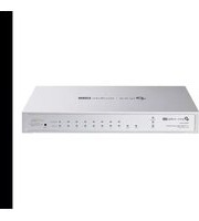



- ACCESSING THE SWITCH
- MANAGING SYSTEM
- USER MANAGEMENT CONFIGURATIONS
- SYSTEM TOOLS CONFIGURATIONS
- EEE CONFIGURATION
- POE CONFIGURATIONS (ONLY FOR CERTAIN DEVICES)
- MANAGEMENT PORT CONFIGURATIONS (ONLY FOR CERTAIN DEVICES)
- POWER SUPPLY CONFIGURATIONS (ONLY FOR CERTAIN DEVICES)
- SDM TEMPLATE CONFIGURATION
- TIME RANGE CONFIGURATION
- CONTROLLER SETTINGS (ONLY FOR CERTAIN DEVICES)
- FILE SYSTEM CONFIGURATIONS
- FTP, SFTP AND SCP CONFIGURATIONS
- EXAMPLE FOR POE CONFIGURATIONS
- APPENDIX: DEFAULT PARAMETERS
- MANAGING PHYSICAL INTERFACES
- CONFIGURING STACK
- CONFIGURING DDM (ONLY FOR CERTAIN DEVICES)
- CONFIGURING LAG
- CONFIGURATION EXAMPLES
- MANAGING MAC ADDRESS TABLE
- MAC ADDRESS TABLE
- MAC ADDRESS CONFIGURATIONS
- SECURITY CONFIGURATIONS
- EXAMPLE FOR SECURITY CONFIGURATIONS
- CONFIGURING 802.1Q VLAN
- CONFIGURING MAC VLAN
- CONFIGURING PROTOCOL VLAN
- CONFIGURING VLAN-VPN (ONLY FOR CERTAIN DEVICES)
- CONFIGURING GVRP
- CONFIGURING PRIVATE VLAN (ONLY FOR CERTAIN DEVICES)
- CONFIGURING MULTICAST
- MULTICAST FILTERING CONFIGURATION
- VIEWING MULTICAST SNOOPING INFORMATION
- PIM CONFIGURATION
- STATIC MULTICAST-ROUTING CONFIGURATION
- LAYER 3 IGMP CONFIGURATION
- CONFIGURING SPANNING TREE
- SPANNING TREE
- STP/RSTP CONFIGURATIONS
- MSTP CONFIGURATIONS
- STP SECURITY CONFIGURATIONS
- CONFIGURATION EXAMPLE FOR MSTP
- CONFIGURING LLDP
- LLDP CONFIGURATIONS
- LLDP-MED CONFIGURATIONS
- VIEWING LLDP SETTINGS
- VIEWING LLDP-MED SETTINGS
- CONFIGURATION EXAMPLE
- CONFIGURING L2PT (ONLY FOR CERTAIN DEVICES)
- CONFIGURING PPPOE ID INSERTION (ONLY FOR CERTAIN DEVICES)
- CONFIGURING LAYER 3 INTERFACES
- CONFIGURING ROUTING
- RIPNG CONFIGURATIONS
- OSPF CONFIGURATIONS
- OSPFV3 CONFIGURATIONS
- EXAMPLE FOR STATIC ROUTING
- CONFIGURING DHCP SERVICE
- DHCP
- DHCP SERVER CONFIGURATION
- DHCP RELAY CONFIGURATION
- DHCP L2 RELAY CONFIGURATION
- CONFIGURING ARP
- CONFIGURING VRRP
- CONFIGURING QOS
- VOICE VLAN CONFIGURATION
- AUTO VOIP CONFIGURATION
- CONFIGURING ACCESS SECURITY
- ACCESS SECURITY
- ACCESS SECURITY CONFIGURATIONS
- CONFIGURING AAA
- CONFIGURING 802.1X
- CONFIGURING PORT SECURITY
- CONFIGURING ACL
- CONFIGURING IPV4 IMPB
- ARP DETECTION CONFIGURATION
- IPV4 SOURCE GUARD CONFIGURATION
- CONFIGURING IPV6 IMPB
- IPV6 IMPB
- IPV6-MAC BINDING CONFIGURATION
- ND DETECTION CONFIGURATION
- IPV6 SOURCE GUARD CONFIGURATION
- CONFIGURING DHCP FILTER
- CONFIGURING DOS DEFEND
- MONITORING THE SYSTEM
- MONITORING TRAFFIC
- MIRRORING TRAFFIC
- CONFIGURING SFLOW (ONLY FOR CERTAIN DEVICES)
- CONFIGURING OAM (ONLY FOR CERTAIN DEVICES)
- ETHERNET OAM
- ETHERNET OAM CONFIGURATIONS
- VIEWING OAM STATISTICS
- CONFIGURING DLDP
- CONFIGURING SNMP & RMON
- DIAGNOSING THE DEVICE & NETWORK
- CONFIGURING SYSTEM LOGS
- ABOUT THIS GUIDE
- INTENDED READERS
- CONVENTIONS
- MORE INFORMATION
- PART
- CHAPTERS
- DETERMINE THE MANAGEMENT METHOD
- NOTE
- CONTROLLER MODE
- STANDALONE MODE
- WEB INTERFACE ACCESS
- LOGIN
- SAVE THE CONFIGURATION FILE
- DISABLE THE WEB SERVER
- CONFIGURE THE SWITCH'S IP ADDRESS AND DEFAULT GATEWAY
- COMMAND LINE INTERFACE ACCESS
- CONSOLE LOGIN (ONLY FOR SWITCH WITH CONSOLE PORT)
- SSH LOGIN
- PASSWORD AUTHENTICATION MODE
- KEY AUTHENTICATION MODE
- TELNET LOGIN
- DISABLE SSH LOGIN
- DISABLE TELNET LOGIN
- COPY RUNNING-CONFIG STARTUP-CONFIG
- CHANGE THE SWITCH'S IP ADDRESS AND DEFAULT GATEWAY
- SWITCH#CONFIGURE
- SYSTEM
- OVERVIEW
- SUPPORTED FEATURES
- SYSTEM INFO
- USER MANAGEMENT
- SYSTEM TOOLS
- EEE
- POE
- PSE
- PD
- STACK
- SDM TEMPLATE
- TIME RANGE
- CONTROLLER SETTINGS
- SYSTEM INFO CONFIGURATIONS
- USING THE GUI
- VIEWING THE SYSTEM SUMMARY
- VIEWING THE PORT STATUS
- VIEWING THE SYSTEM INFORMATION
- CONFIGURING THE DEVICE DESCRIPTION
- CONFIGURING THE SYSTEM TIME
- CONFIGURING THE DAYLIGHT SAVING TIME
- CLICK APPLY
- CONFIGURING LED (ONLY FOR CERTAIN DEVICES)
- USING THE CLI
- SHOW SYSTEM-INFO
- SWITCH#SHOW SYSTEM-INFO
- STEP 5 SHOW SYSTEM-INFO
- STEP 6 END
- STEP 7 COPY RUNNING-CONFIG STARTUP-CONFIG
- SWITCH(CONFIG)#SHOW SYSTEM-INFO
- SWITCH(CONFIG)#END
- STEP 1 CONFIGURE
- SHOW SYSTEM-TIME
- SHOW SYSTEM-TIME NTP
- STEP 5 COPY RUNNING-CONFIG STARTUP-CONFIG
- SWITCH(CONFIG)#SHOW SYSTEM-TIME NTP
- SWITCH(CONFIG)#SHOW SYSTEM-TIME DST
- FOLLOW THESE STEPS TO CONFIGURE THE LED STATUS
- STEP 2 LED {ON | OFF}
- CREATING ACCOUNTS
- CONFIGURING ENABLE PASSWORD
- STEP 3 SHOW USER ACCOUNT-LIST
- STEP 4 END
- TIPS
- SWITCH#CONFIG
- WITH SYSTEM TOOLS, YOU CAN
- CONFIGURING THE BOOT FILE
- RESTORING THE CONFIGURATION OF THE SWITCH
- BACKING UP THE CONFIGURATION FILE
- UPGRADING THE FIRMWARE
- CONFIGURING DHCP AUTO INSTALL (ONLY FOR CERTAIN DEVICES)
- IF AUTO INSTALL FAILS TO GET THE CONFIGURATION FILE, THIS PROCEDURE WILL BE RETRIED EVERY 10 MINUTES. - IF DHCP AUTO INSTALL IS ENABLED AND THERE IS NO LAYER 3 INTERFACE WHOSE IP ADDRESS MODE IS DHCP, THE SWITCH WILL CHOOSE A LAYER 3 INTERFACE AND CHANGE ITS IP ADDRESS MODE TO DHCP
- THERE ARE TWO METHODS TO REBOOT THE SWITCH: MANUALLY REBOOT THE SWITCH AND CONFIGURE A REBOOT SCHEDULE TO AUTOMATICALLY REBOOT THE SWITCH
- CHOOSE THE MENU SYSTEM > SYSTEM TOOLS > SYSTEM REBOOT > SYSTEM REBOOT TO LOAD THE FOLLOWING PAGE
- CONFIGURING REBOOT SCHEDULE
- RESETTING THE SWITCH
- SWITCH(CONFIG)#SHOW BOOT
- SWITCH>ENABLE
- UPGRADING THE MCU-FIRMWARE
- STEP 6 BOOT AUTOINSTALL START
- STEP 8 COPY RUNNING-CONFIG STARTUP-CONFIG
- SWITCH(CONFIG)#SHOW BOOT AUTOINSTALL
- REBOOTING THE SWITCH
- MANUALLY REBOOTING THE SWITCH
- WITH THE POE FEATURE, YOU CAN
- CONFIGURING THE POE PARAMETERS MANUALLY
- CONFIGURING THE POE PARAMETERS USING THE PROFILE
- CREATING A POE PROFILE
- BINDING THE PROFILE TO THE CORRESPONDING PORTS
- CONFIGURING THE POE AUTO RECOVERY PARAMETERS MANUALLY
- SWITCH(CONFIG-IF)#POWER INLINE CONSUMPTION CLASS
- SWITCH(CONFIG-IF)#SHOW POWER INLINE
- SWITCH(CONFIG-IF)#SHOW POWER INLINE CONFIGURATION INTERFACE GIGABITETHERNET
- SWITCH(CONFIG-IF)#SHOW POWER INLINE INFORMATION INTERFACE GIGABITETHERNET
- SWITCH(CONFIG-IF)#END
- SWITCH#COPY RUNNING-CONFIG STARTUP-CONFIG
- MANAGEMENT PORT CONFIGURATIONS (ONLY FOR CERTAIN
- SWITCH(CONFIG)#SHOW MANAGEMENT-PORT
- CONFIGURING THE POWER BACKUP MODE
- SWITCH(CONFIG)#SHOW SDM PREFER ENTERPRISEV
- SWITCH(CONFIG)#SDM PREFER ENTERPRISEV
- ADDING TIME RANGE ENTRIES
- CONFIGURING HOLIDAY
- STEP 2 TIME-RANGE
- STEP 3 HOLIDAY { EXCLUDE | INCLUDE }
- STEP 4 ABSOLUTE FROM
- STEP 5 PERIODIC START
- STEP 6 SHOW TIME-RANGE
- STEP 7 END
- SWITCH(CONFIG-TIME-RANGE)#SHOW TIME-RANGE
- SWITCH(CONFIG-TIME-RANGE)#END
- SWITCH(CONFIG)#SHOW HOLIDAY
- ENABLING CLOUD-BASED CONTROLLER MANAGEMENT
- CONFIGURING CONTROLLER INFORM URL
- SWITCH(CONFIG)#SHOW CONTROLLER
- CONFIGURING THE FILE SYSTEM
- USING THE FTP
- USING THE SFTP
- USING THE SCP
- NETWORK REQUIREMENTS
- CONFIGURING SCHEME
- VERIFY THE CONFIGURATION
- THE DEFAULT SETTINGS FOR TIME RANGE ARE LISTED IN THE FOLLOWING TABLE
- PHYSICAL INTERFACE
- BASIC PARAMETERS
- PORT ISOLATION
- LOOPBACK DETECTION
- BASIC PARAMETERS CONFIGURATIONS
- DESCRIPTION STRING
- SHUTDOWN
- NO SHUTDOWN
- DUPLEX { AUTO | FULL | HALF }
- FLOW-CONTROL
- PORT ISOLATION CONFIGURATIONS
- LOOPBACK DETECTION CONFIGURATION
- STEP 2 LOOPBACK-DETECTION
- STEP 3 LOOPBACK-DETECTION INTERVAL
- STEP 4 LOOPBACK-DETECTION RECOVERY-TIME
- STEP 5 INTERFACE {VLAN
- STEP 6 LOOPBACK-DETECTION
- STEP
- STEP 9 SHOW LOOPBACK-DETECTION GLOBAL
- SWITCH(CONFIG)#LOOPBACK-DETECTION
- SWITCH(CONFIG)#SHOW LOOPBACK-DETECTION GLOBAL
- EXAMPLE FOR PORT ISOLATION
- CONFIGURATION SCHEME
- EXAMPLE FOR LOOPBACK DETECTION
- STACK CONCEPTS
- STACK ROLE
- UNIT ID
- PRIORITY
- STACK EVENTS
- STACK OPERATION PROCEDURE
- CONNECTING THE STACK MEMBERS
- TOPOLOGY COLLECTION
- MASTER ELECTION
- STACK MANAGEMENT AND MAINTENANCE
- STACK TOPOLOGY
- CHAIN TOPOLOGY
- RING TOPOLOGY
- STAR TOPOLOGY
- VIEWING THE STACK INFORMATION
- CONFIGURING THE PROVISION INFO
- CONFIGURING THE PROVISIONED MEMBER
- CONFIGURING THE STACK MEMBER
- CONFIGURING THE STACK PORT GROUP
- STATUS
- CONFIGURING STACK SYSTEM NAME
- ENTERING STACK PORT GROUP VIEW
- CONFIGURING STACK PORT
- VIEWING CURRENT STACK PORT GROUP INFO
- CONFIGURING STACK DEVICE PRIORITY
- MODIFYING STACK UNIT ID
- CONFIGURING PROVISION ENTRIES
- VIEWING STACK INFO
- CONFIGURING DDM
- DDM CONFIGURATION
- CONFIGURING DDM GLOBALLY
- CONFIGURING THE THRESHOLD
- CONFIGURING THE TEMPERATURE THRESHOLD
- CONFIGURING THE VOLTAGE THRESHOLD
- CONFIGURING THE BIAS CURRENT THRESHOLD
- CONFIGURING THE TX POWER THRESHOLD
- CONFIGURING THE RX POWER THRESHOLD
- VIEWING DDM STATUS
- STEP 3 DDM STATE ENABLE
- STEP 4 SHOW DDM CONFIGURATION STATE
- STEP 5 END
- STEP 6 COPY RUNNING-CONFIG STARTUP-CONFIG
- CONFIGURING DDM SHUTDOWN
- CONFIGURING VOLTAGE THRESHOLD
- CONFIGURING BIAS CURRENT THRESHOLD
- CONFIGURING RX POWER THRESHOLD
- CONFIGURING TX POWER THRESHOLD
- VIEWING DDM CONFIGURATION
- STEP 2 SHOW DDM STATUS
- STEP 3 END
- LAG
- STATIC LAG
- LACP
- LAG CONFIGURATION
- CONFIGURATION GUIDELINES
- CONFIGURING LOAD-BALANCING ALGORITHM
- HASH ALGORITHM
- CONFIGURING STATIC LAG OR LACP
- CONFIGURING STATIC LAG
- CONFIGURING LACP
- STEP 3 SHOW ETHERCHANNEL LOAD-BALANCE
- SWITCH(CONFIG)#SHOW ETHERCHANNEL LOAD-BALANCE
- STEP 3 CHANNEL-GROUP
- SWITCH(CONFIG-IF-RANGE)#END
- STEP 2 LACP SYSTEM-PRIORITY PRI
- STEP 3 INTERFACE {FASTETHERNET PORT | RANGE FASTETHERNET PORT-LIST | GIGABITETHERNET PORT | RANGE GIGABITETHERNET PORT-LIST | TEN-GIGABITETHERNET PORT | RANGE TEN-GIGABITETHERNET PORT-LIST ]}
- STEP 4 CHANNEL-GROUP NUM MODE {ACTIVE | PASSIVE}
- STEP 5 LACP PORT-PRIORITY PRI
- SWITCH(CONFIG)#LACP SYSTEM-PRIORITY
- SWITCH(CONFIG)#SHOW LACP SYS-ID
- SWITCH(CONFIG-IF-RANGE)#SHOW LACP INTERNAL
- EXAMPLE FOR STATIC LAG
- EXAMPLE FOR LACP
- ADDRESS CONFIGURATIONS
- DYNAMIC ADDRESS
- STATIC ADDRESS
- FILTERING ADDRESS
- CONFIGURING MAC NOTIFICATION TRAPS
- LIMITING THE NUMBER OF MAC ADDRESSES IN VLANS
- ADDING STATIC MAC ADDRESS ENTRIES
- CLICK CREATE
- BINDING DYNAMIC ADDRESS ENTRIES
- MODIFYING THE AGING TIME OF DYNAMIC ADDRESS ENTRIES
- ADDING MAC FILTERING ADDRESS ENTRIES
- VIEWING ADDRESS TABLE ENTRIES
- STEP 2 MAC ADDRESS-TABLE AGING-TIME
- STEP 4 COPY RUNNING-CONFIG STARTUP-CONFIG
- STEP 2 MAC ADDRESS-TABLE FILTERING
- LIMITING THE NUMBER OF MAC ADDRESSES LEARNED IN VLANS
- FOR CERTAIN DEVICES
- STEP 2 MAC ADDRESS-TABLE VLAN-SECURITY MODE {DROP | FORWARD}
- STEP 3 MAC ADDRESS-TABLE VLAN-SECURITY VID
- VID MAX-LEARN NUM
- STEP 2 MAC ADDRESS-TABLE SECURITY VID
- VERIFY THE CONFIGURATIONS
- CONFIGURING
- Q VLAN
- Q VLAN CONFIGURATION
- CONFIGURING THE VLAN
- CONFIGURING PORT PARAMETERS FOR 802.1Q VLAN
- CREATING A VLAN
- SWITCH(CONFIG)#VLAN
- SWITCH(CONFIG-VLAN)#SHOW VLAN ID
- SWITCH(CONFIG-VLAN)#END
- ADDING THE PORT TO THE SPECIFIED VLAN
- CONFIGURING THE PORT
- NETWORK TOPOLOGY
- MAC VLAN CONFIGURATION
- BINDING THE MAC ADDRESS TO THE VLAN
- ENABLING MAC VLAN FOR THE PORT
- CONFIGURATIONS FOR SWITCH 1 AND SWITCH
- CONFIGURATIONS FOR SWITCH
- SWITCH
- PROTOCOL VLAN CONFIGURATION
- CREATING PROTOCOL TEMPLATE
- SELECT THE DESIRED PORTS. CLICK CREATE
- CREATING A PROTOCOL TEMPLATE
- SWITCH(CONFIG)#SHOW PROTOCOL-VLAN TEMPLATE
- STEP 4 SHOW PROTOCOL-VLAN VLAN
- STEP 5 INTERFACE {FASTETHERNET
- STEP 6 PROTOCOL-VLAN GROUP
- SWITCH(CONFIG-IF)#PROTOCOL-VLAN GROUP
- SWITCH(CONFIG-IF)#SHOW PROTOCOL-VLAN VLAN
- CHOOSE THE MENU L2 FEATURES > VLAN > 802.1Q VLAN > VLAN CONFIG AND CLICK ADD TO LOAD THE FOLLOWING PAGE. CREATE VLAN 10, AND ADD TAGGED PORT 1/0/1 AND UNTAGGED PORT 1/0/2 TO VLAN 10. CLICK CREATE
- CONFIGURING VLAN-VPN
- VLAN-VPN
- BASIC VLAN-VPN
- FLEXIBLE VLAN-VPN
- BASIC VLAN-VPN CONFIGURATION
- CONFIGURING BASIC VLAN-VPN
- STEP 5 SWITCHPORT DOT1Q-TUNNEL TPID
- STEP 6 SWITCHPORT DOT1Q-TUNNEL MISSDROP
- STEP 7 SWITCHPORT DOT1Q-TUNNEL USE_INNER_PRIORITY
- STEP 8 SHOW DOT1Q-TUNNEL
- STEP 9 SHOW DOT1Q-TUNNEL INTERFACE
- STEP 10 END
- STEP 11 COPY RUNNING-CONFIG STARTUP-CONFIG
- SWITCH(CONFIG-IF)#SHOW DOT1Q-TUNNEL
- FLEXIBLE VLAN-VPN CONFIGURATION
- SWITCH(CONFIG)#DOT1Q-TUNNEL MAPPING
- SWITCH(CONFIG)#SHOW DOT1Q-TUNNEL
- EXAMPLE FOR BASIC VLAN VPN
- CONFIGURING SWITCH
- VERIFY THE VLAN VPN CONFIGURATIONS ON SWITCH
- EXAMPLE FOR FLEXIBLE VLAN VPN
- GVRP CONFIGURATION
- STEP 4 GVRP
- STEP 5 GVRP REGISTRATION { NORMAL | FIXED | FORBIDDEN }
- STEP 7 SHOW GVRP GLOBAL
- CONFIGURING PRIVATE VLAN
- PRIVATE VLAN CONFIGURATIONS
- CREATING PRIVATE VLAN
- CONFIGURING THE UP-LINK PORT
- STEP 4 SWITCHPORT PRIVATE-VLAN MAPPING
- STEP 5 SHOW VLAN PRIVATE-VLAN
- STEP 6 SHOW VLAN PRIVATE-VLAN INTERFACE [FASTETHERNET
- GIGABITETHERNET PORT | PORT-CHANNEL LAG-ID]
- CONFIGURING THE DOWN-LINK PORT
- CONFIGURATIONS FOR SWITCH A
- CONFIGURATIONS FOR SWITCH C
- SWITCH A
- SWITCH C
- LAYER 2 MULTICAST
- DEMONSTRATED AS BELOW
- IGMP QUERIER
- SNOOPING SWITCH
- ROUTER PORT
- MEMBER PORT
- LAYER 2 MULTICAST PROTOCOL FOR IPV4: IGMP SNOOPING
- LAYER 2 MULTICAST PROTOCOL FOR IPV6: MLD SNOOPING
- MULTICAST VLAN REGISTRATION (MVR)
- MULTICAST FILTERING
- PROTOCOL INDEPENDENT MULTICAST
- STATIC MULTICAST ROUTING
- IP IGMP
- IGMP SNOOPING CONFIGURATION
- CONFIGURING IGMP SNOOPING GLOBALLY
- CONFIGURING IGMP SNOOPING FOR VLANS
- CLICK SAVE
- CONFIGURING IGMP SNOOPING FOR PORTS
- CONFIGURING HOSTS TO STATICALLY JOIN A GROUP
- CONFIGURING IGMP ACCOUNTING AND AUTHENTICATION FEATURES
- SWITCH(CONFIG)#SHOW IP IGMP SNOOPING
- STEP 2 IP IGMP SNOOPING VLAN-CONFIG
- STEP 3 IP IGMP SNOOPING VLAN-CONFIG
- STEP 4 IP IGMP SNOOPING VLAN-CONFIG
- STEP 5 IP IGMP SNOOPING VLAN-CONFIG
- VLAN-ID-LIST REPORT-SUPPRESSION
- STEP 6 IP IGMP SNOOPING VLAN-CONFIG
- VLAN-ID-LIST IMMEDIATE-LEAVE
- STEP 7 IP IGMP SNOOPING VLAN-CONFIG
- VLAN-ID-LIST RPORT INTERFACE { FASTETHERNET PORT-LIST
- GIGABITETHERNET PORT-LIST | TEN-GIGABITETHERNET PORT-LIST | PORT-CHANNEL LAG-LIST}
- STEP 3 IP IGMP SNOOPING ACCOUNTING
- STEP 4 SHOW IP IGMP SNOOPING
- FOLLOW THESE STEPS TO ENABLE IGMP AUTHENTICATION FOR PORTS
- MLD SNOOPING CONFIGURATION
- CONFIGURING MLD SNOOPING GLOBALLY
- CONFIGURING MLD SNOOPING FOR VLANS
- CONFIGURING MLD SNOOPING FOR PORTS
- STEP 3 IPV6 MLD SNOOPING DROP-UNKNOWN
- STEP 4 SHOW IPV6 MLD SNOOPING
- STEP 2 IPV6 MLD SNOOPING VLAN-CONFIG
- STEP 3 IPV6 MLD SNOOPING VLAN-CONFIG
- STEP 4 IPV6 MLD SNOOPING VLAN-CONFIG
- STEP 5 IPV6 MLD SNOOPING VLAN-CONFIG VLAN-ID-LIST REPORT-SUPPRESSION
- STEP 6 IPV6 MLD SNOOPING VLAN-CONFIG VLAN-ID-LIST IMMEDIATE-LEAVE
- STEP 7 IPV6 MLD SNOOPING VLAN-CONFIG VLAN-ID-LIST RPORT INTERFACE { FASTETHERNET PORT-LIST | GIGABITETHERNET PORT-LIST | TEN-GIGABITETHERNET PORT-LIST | PORT-CHANNEL LAG-LIST }
- STEP 8 IPV6 MLD SNOOPING VLAN-CONFIG VLAN-ID-LIST ROUTER-PORTS-FORBIDDEN INTERFACE { FASTETHERNET PORT-LIST | GIGABITETHERNET PORT-LIST | TEN-GIGABITETHERNET PORT-LIST | PORT-CHANNEL LAG-LIST }
- STEP 9 IPV6 MLD SNOOPING VLAN-CONFIG
- VLAN-ID-LIST QUERIER
- STEP 10 SHOW IPV6 MLD SNOOPING VLAN
- VLAN-ID
- STEP 11 END
- STEP 12 COPY RUNNING-CONFIG STARTUP-CONFIG
- SWITCH(CONFIG)#SHOW IPV6 MLD SNOOPING VLAN
- MVR CONFIGURATION
- CONFIGURING 802.1Q VLANS
- CONFIGURING MVR GLOBALLY
- ADDING MULTICAST GROUPS TO MVR
- CONFIGURING MVR FOR THE PORT
- FAST LEAVE
- (OPTIONAL) ADDING PORTS TO MVR GROUPS STATICALLY
- STEP 2 MVR
- STEP 3: MVR MODE { COMPATIBLE | DYNAMIC }
- STEP 4: MVR VLAN
- STEP 5: MVR QUERYTIME
- CONFIGURING MVR FOR THE PORTS
- CREATING THE MULTICAST PROFILE
- CONFIGURE MULTICAST FILTERING FOR PORTS
- CREATING IGMP PROFILE (MULTICAST PROFILE FOR IPV4)
- STEP 3 PERMIT
- DENY
- STEP 4 RANGE START-IP END-IP
- STEP 5 SHOW IP IGMP PROFILE [ ID]
- CREATING MLD PROFILE (MULTICAST PROFILE FOR IPV6)
- BINDING THE PROFILE TO PORTS
- BINDING THE MLD PROFILE TO PORTS
- STEP 4 IPV6 MLD SNOOPING MAX-GROUPS
- STEP 5 IPV6 MLD SNOOPING MAX-GROUPS ACTION {DROP | REPLACE}
- STEP 6 SHOW IPV6 MLD PROFILE [ ID]
- VIEWING IPV4 MULTICAST TABLE
- VIEWING IPV4 MULTICAST STATISTICS ON EACH PORT
- VIEWING IPV6 MULTICAST TABLE
- VIEWING IPV6 MULTICAST STATISTICS ON EACH PORT
- VIEWING IPV4 MULTICAST SNOOPING INFORMATION
- VIEWING IPV6 MULTICAST SNOOPING CONFIGURATIONS
- CONFIGURING IP MULTICAST-ROUTING GLOBALLY
- CONFIGURING IP PIM GLOBALLY
- CONFIGURING IP PIM ON SPECIFIED PORT
- CONFIGURING IP PIM HELLO-INTERVAL
- VIEWING IP MULTICAST INFO
- STEP 2 SHOW IP MULTICAST
- SWITCH(CONFIG)# SHOW IP MULTICAST
- VIEWING IP MROUTE
- VIEWING IP PIM INTERFACE INFO
- SWITCH(CONFIG)# SHOW IP PIM INTERFACE VLAN
- VIEWING IP PIM NEIGHBOR INFO
- SWITCH(CONFIG)# SHOW IP PIM NEIGHBOR
- VIEWING IP PIM STATISTICS
- SWITCH(CONFIG)# SHOW IP PIM STATISTIC
- CONFIGURING STATIC MULTICAST-ROUTING ENTRIES
- VIEWING IP MROUTE STATIC INFO
- CONFIGURING IP IGMP GLOBALLY
- CONFIGURING IP IGMP ON PORTS
- STEP 3 IP IGMP VERSION {1|2|3}
- STEP 4 IP IGMP LAST-MEMBER-QUERY-COUNT COUNT
- STEP 5 IP IGMP LAST-MEMBER-QUERY-INTERVAL INTERVAL
- STEP 6 IP IGMP QUERY-INTERVAL INTERVAL
- STEP 7 IP IGMP QUERY-MAX-RESPONSE-TIME TIME
- STEP 8 IP IGMP ROBUSTNESS ROBUSTNESS
- STEP 9 IP IGMP STARTUP-QUERY-INTERVAL INTERVAL
- STEP 10 IP IGMP LAST-MEMBER-QUERY-COUNT COUNT
- STEP 11 SHOW IP IGMP
- STEP 12 SHOW IP IGMP GROUPS { GROUP-ADDRESS } [ DETAIL]
- STEP 13 SHOW IP IGMP GROUPS INTERFACE { FASTETHERNET | GIGABITETHERNET | TEN-GIGABITETHERNET PORT | PORT-CHANNEL [PORT-CHANNEL-LIST] | DETAIL }
- STEP 14 SHOW IP IGMP GROUPS INTERFACE VLAN VLAN-ID {DETAIL}
- STEP 15 SHOW IP IGMP INTERFACE { FASTETHERNET | GIGABITETHERNET | TEN-GIGABITETHERNET PORT | PORT-CHANNEL [PORT-CHANNEL-LIST] | STATISTIC }
- STEP 16 SHOW IP IGMP INTERFACE VLAN VLAN-ID {STATISTIC}
- SWITCH(CONFIG-IF)#SHOW IP IGMP GROUPS INTERFACE VLAN
- SWITCH(CONFIG-IF)#SHOW IP IGMP INTERFACE GIGABITETHERNET 1/0/1 STATISTIC
- SWITCH(CONFIG-IF)#SHOW IP IGMP INTERFACE VLAN
- EXAMPLE FOR CONFIGURING BASIC IGMP SNOOPING
- EXAMPLE FOR CONFIGURING MVR
- EXAMPLE FOR CONFIGURING UNKNOWN MULTICAST AND FAST LEAVE
- NETWORK REQUIREMENT
- EXAMPLE FOR CONFIGURING MULTICAST FILTERING
- DEFAULT PARAMETERS FOR IGMP SNOOPING
- DEFAULT PARAMETERS FOR MLD SNOOPING
- DEFAULT PARAMETERS FOR MVR
- DEFAULT PARAMETERS FOR MULTICAST FILTERING
- DEFAULT PARAMETERS FOR PIM
- DEFAULT PARAMETERS FOR STATIC MULTICAST-ROUTING
- DEFAULT PARAMETERS FOR LAYER 3 IGMP
- STP
- MSTP
- BASIC CONCEPTS
- STP/RSTP CONCEPTS
- ROOT BRIDGE
- BRIDGE ID
- PORT ROLE
- ROOT PORT
- DESIGNATED PORT
- ALTERNATE PORT
- BACKUP PORT
- DISABLE PORT
- PORT STATUS
- BLOCKING
- LISTENING
- LEARNING
- FORWARDING
- DISABLED
- PATH COST
- ROOT PATH COST
- BPDU
- MSTP CONCEPTS
- MST REGION
- MST INSTANCE
- VLAN-INSTANCE MAPPING
- IST
- CST
- CIST
- STP SECURITY
- TC PROTECT
- CONFIGURING STP/RSTP PARAMETERS ON PORTS
- CONFIGURING STP/RSTP GLOBALLY
- VERIFYING THE STP/RSTP CONFIGURATIONS
- STEP 3 SPANNING-TREE
- STEP 5 SPANNING-TREE MCHECK
- CONFIGURING GLOBAL STP/RSTP PARAMETERS
- STEP 2 SPANNING-TREE PRIORITY PRI
- STEP 3 SPANNING-TREE TIMER {[ FORWARD-TIME FORWARD-TIME] [HELLO-TIME HELLO-TIME] [MAX-AGE MAX-AGE]}
- STEP 4 SPANNING-TREE HOLD-COUNT VALUE
- STEP 5 SHOW SPANNING-TREE BRIDGE
- ENABLING STP/RSTP GLOBALLY
- STEP 2 SPANNING-TREE MODE {STP | RSTP}
- STEP 4 SHOW SPANNING-TREE ACTIVE
- CONFIGURING PARAMETERS ON PORTS IN CIST
- CONFIGURING THE MSTP REGION
- CONFIGURING PARAMETERS ON PORTS IN THE INSTANCE
- CONFIGURING MSTP GLOBALLY
- VERIFYING THE MSTP CONFIGURATIONS
- STEP 4 SPANNING-TREE COMMON-CONFIG [ PORT-PRIORITY PRI ] [ EXT-COST EXT-COST ] [ INT-COST INT-COST ][ PORTFAST { ENABLE | DISABLE }] [ POINT-TO-POINT { AUTO | OPEN | CLOSE }]
- CONFIGURING THE MST REGION
- STEP 2 SPANNING-TREE MST INSTANCE
- STEP 3 SPANNING-TREE MST CONFIGURATION
- STEP 4 NAME
- STEP 5 REVISION
- STEP 6 INSTANCE
- SWITCH(CONFIG)#SPANNING-TREE MST CONFIGURATION
- SWITCH(CONFIG-MST)#SHOW SPANNING-TREE MST CONFIGURATION
- SWITCH(CONFIG-MST)#END
- CONFIGURING GLOBAL MSTP PARAMETERS
- STEP 3 SPANNING-TREE TIMER {[ FORWARD-TIME FORWARD-TIME ] [ HELLO-TIME HELLO-TIME ] [ MAX-AGE MAX-AGE] }
- STEP 4: SPANNING-TREE HOLD-COUNT VALUE
- ENABLING SPANNING TREE GLOBALLY
- STEP 2 SPANNING-TREE MODE MSTP
- SWITCH(CONFIG)#SPANNING-TREE MODE MSTP
- SWITCH(CONFIG)#SPANNING-TREE
- SWITCH(CONFIG)#SHOW SPANNING-TREE ACTIVE
- CONFIGURING THE STP SECURITY
- STEP 3 SPANNING-TREE GUARD LOOP
- STEP 4 SPANNING-TREE GUARD ROOT
- STEP 5 SPANNING-TREE GUARD TC
- STEP 6 SPANNING-TREE BPDUGUARD
- STEP 7 SPANNING-TREE BPDUFILTER
- CONFIGURATIONS FOR SWITCH B
- SWITCH B
- LLDP
- CONFIGURING LLDP GLOBALLY
- CONFIGURING LLDP FOR THE PORT
- GLOBAL CONFIG
- STEP 2 LLDP
- STEP 3 LLDP FORWARD_MESSAGE
- STEP 4 LLDP HOLD-MULTIPLIER
- STEP 5 LLDP TIMER { TX-INTERVAL
- STEP 6 SHOW LLDP
- SWITCH(CONFIG)#LLDP
- SWITCH(CONFIG)#LLDP HOLD-MULTIPLIER
- SWITCH(CONFIG)#LLDP TIMER TX-INTERVAL 30 TX-DELAY 2 REINIT-DELAY 3 NOTIFY-INTERVAL 5 FAST-COUNT
- SWITCH(CONFIG)#SHOW LLDP
- PORT CONFIG
- STEP 3 LLDP RECEIVE
- STEP 4 LLDP TRANSMIT
- STEP 5 LLDP SNMP-TRAP
- STEP 6 LLDP TLV-SELECT
- STEP 7 SHOW LLDP INTERFACE { FASTETHERNET
- STEP 8 END
- STEP 9 COPY RUNNING-CONFIG STARTUP-CONFIG
- CONFIGURING LLDP-MED GLOBALLY
- CONFIGURING LLDP-MED FOR PORTS
- STEP 3 LLDP MED-STATUS
- STEP 4 LLDP MED-TLV-SELECT { [INVENTORY-MANAGEMENT] [LOCATION] [NETWORK-POLICY] [POWER-MANAGEMENT] [ALL] }
- USING GUI
- VIEWING LLDP DEVICE INFO
- VIEWING THE NEIGHBOR INFO
- VIEWING LLDP STATISTICS
- USING CLI
- CONFIGURATION EXAMPLE FOR LLDP
- VIEW LLDP SETTINGS GLOBALLY
- VIEW LLDP SETTINGS ON EACH PORT
- VIEW THE LOCAL INFO
- VIEW THE NEIGHBOR INFO
- EXAMPLE FOR LLDP-MED
- VIEW VLAN SETTINGS
- VIEW VOIP SETTINGS
- VIEW GLOBAL LLDP SETTINGS
- VIEW LLDP-MED SETTINGS ON PORT
- DEFAULT LLDP SETTINGS
- DEFAULT LLDP-MED SETTINGS
- CONFIGURING L2PT
- L2PT CONFIGURATION
- CONFIGURING PPPOE ID INSERTION
- PPPOE ID INSERTION CONFIGURATION
- STEP 5 PPPOE CIRCUIT-ID TYPE { MAC | IP | UDF [
- VALUE] | UDF-ONLY [VALUE] }
- STEP 6 PPPOE REMOTE-ID [
- VALUE]
- STEP 7 SHOW PPPOE GLOBAL
- STEP 8 SHOW PPPOE INTERFACE { FASTETHERNET PORT}
- PORT | GIGABITETHERNET PORT | TEN-GIGABITETHERNET
- STEP 9 END
- STEP 10 COPY RUNNING-CONFIG STARTUP-CONFIG
- SWITCH(CONFIG)#PPPOE ID-INSERTION
- SWITCH(CONFIG)#INTERFACE GIGABITETHERNET
- SWITCH(CONFIG-IF)#PPPOE CIRCUIT-ID
- SWITCH(CONFIG-IF)#PPPOE CIRCUIT-ID TYPE UDF-ONLY
- SWITCH(CONFIG-IF)#PPPOE REMOTE-ID HOST
- SWITCH(CONFIG-IF)#SHOW PPPOE GLOBAL
- LAYER 3 INTERFACE CONFIGURATIONS
- CREATING A LAYER 3 INTERFACE
- INTERFACE
- CONFIGURING IPV4 PARAMETERS OF THE INTERFACE
- CONFIGURING IPV6 PARAMETERS OF THE INTERFACE
- VIA RA MESSAGE
- VIA DHCPV6 SERVER
- MANUALLY
- GLOBAL ADDRESS
- VIEWING DETAIL INFORMATION OF THE INTERFACE
- STEP 2 INTERFACE {
- STEP 3 AUTOMATICALLY ASSIGN AN IP ADDRESS FOR THE INTERFACE VIA DHCP OR BOOTP
- IP ADDRESS-ALLOC { DHCP | BOOTP }
- MANUALLY ASSIGN AN IP ADDRESS FOR THE INTERFACE
- IP ADDRESS {IP-ADDR} {MASK} [SECONDARY]
- STEP 4: SHOW IP INTERFACE BRIEF
- STEP 5: END
- STEP 3 IPV6 ENABLE
- IPV6 ADDRESS IPV6-ADDR LINK-LOCAL
- VERIFY THE VLAN INTERFACE CONFIGURATIONS
- IPV4 STATIC ROUTING CONFIGURATION
- SWITCH(CONFIG)#SHOW IP ROUTE
- IPV6 STATIC ROUTING CONFIGURATION
- FOLLOW THESE STEPS TO ENABLE IPV6 ROUTING FUNCTION AND CREATE AN IPV6 STATIC ROUTE
- ENTER GLOBAL CONFIGURATION MODE
- ENABLE THE IPV6 ROUTING FUNCTION ON THE SPECIFIED LAYER 3 INTERFACE
- IPV6-DEST-ADDRESS} { NEXT-HOP-ADDRESS } [DISTANCE ]
- STEP 4 SHOW IPV6 ROUTE [STATIC | CONNECTED]
- SWITCH(CONFIG)#SHOW IPV6 ROUTE STATIC
- VIEWING ROUTING TABLE
- VIEWING IPV4 ROUTING TABLE
- VIEWING IPV6 ROUTING TABLE
- RIP CONFIGURATIONS
- ENABLING RIP FUNCTION
- ENABLING RIP FUNCTION FOR SPECIFIC NETWORK SEGMENT
- STEP 2 ROUTER RIP
- STEP 3 NETWORK
- CONFIGURING RIP MESSAGE VERSION
- STEP 3 VERSION
- CONFIGURING RIP TIMER
- CONFIGURING MANAGEMENT DISTANCE
- STEP 3 DISTANCE
- ENABLING AUTO-SUMMARY FUNCTION
- STEP 3 AUTO-SUMMARY
- SETTING DEFAULT METRIC
- CONFIGURING RIP REDIRECTION
- ENABLING ECMP FUNCTION
- INTRODUCING DEFAULT ROUTE
- STEP 3 DEFAULT-INFORMATION ORIGINATE
- CONFIGURING RIP NEIGHBOR
- CONFIGURING PASSIVE-INTERFACE
- CONFIGURING AUTHENTICATION MODE
- CONFIGURING AUTHENTICATION STRING
- CONFIGURING AUTHENTICATION KEY-CHAIN
- CONFIGURING RECEIVE VERSION
- STEP 3 IP RIP RECEIVE VERSION {1 | 2}
- CONFIGURING SEND VERSION
- STEP 2 INTERFACE {VLAN
- STEP 3 IP RIP SEND VERSION {1 | 2}
- CONFIGURING SPLIT HORIZON
- ENABLING RIPV2 PACKET BROADCAST
- STEP 3 IP RIP V2-BROADCAST
- VIEWING RIP ROUTING TABLE
- STEP 1 SHOW IP RIP
- SWITCH#SHOW IP RIP
- SWITCH#SHOW IP RIP STATUS
- CLEARING IP RIP
- STEP 1 CLEAR IP RIP
- SWITCH#CLEAR IP RIP
- ENABLING RIPNG FUNCTION
- STEP 2 ROUTER RIPNG
- ENABLING RIP FUNCTION ON SPECIFIC PORT
- CONFIGURING RIPNG TIMER
- STEP 3 TIMER BASIC UPDATE-VALUE TIMEOUT-VALUE GARBAGE-COLLECT-VALUE
- SWITCH(CONFIG)#ROUTER RIPNG
- CONFIGURING RIPNG REDIRECTION
- VIEWING RIPNG ROUTING TABLE
- SWITCH#SHOW IPV6 RIP
- VIEWING IPV6 STATUS
- SWITCH#SHOW IPV6 RIP STATUS
- CLEARING IPV6 RIP
- CONFIGURING ROUTER OSPF
- CONFIGURING ROUTER ID
- STEP 2 ROUTER OSPF PROCESS-ID
- STEP 3 ROUTER-ID ROUTER-ID
- CONFIGURING NETWORK
- CONFIGURING MAX-PATHS
- CONFIGURING ASBR
- STEP 2 ROUTER OSPF
- STEP 3 REDISTRIBUTE { CONNECTED | STATIC | RIP | OSPF
- STEP 5: COPY RUNNING-CONFIG STARTUP-CONFIG
- SWITCH(CONFIG)#ROUTER OSPF
- SWITCH(CONFIG-ROUTER)#REDISTRIBUTE RIP METRIC-TYPE
- CONFIGURING DEFAULT-METRIC
- STEP 1: CONFIGURE
- CONFIGURING DEFAULT-INFORMATION ORIGINATE
- STEP 3 DEFAULT-INFORMATION ORIGINATE [ALWAYS] [METRIC
- COST ] [METRIC-TYPE TYPE]
- CONFIGURING AUTO-COST
- STEP 3 AUTO-COST REFERENCE-BANDWIDTH
- BANDWIDTH
- CONFIGURING OSPF ADMINISTRATIVE DISTANCE
- PROCESS-ID
- ADMINISTRATIVE-DISTANCE
- CONFIGURING COMPUTING DELAY AND INTERVAL
- STEP 3 TIMERS THROTTLE SPF
- CONFIGURING RFC
- STEP 3 COMPATIBLE RFC
- DEFINING STUB AREA
- STEP 3 AREA
- DEFINING NSSA AREA
- CONFIGURING AREA DEFAULT-COST
- CONFIGURING SUMMARY ROUTE
- CONFIGURING AREA AUTHENTICATION
- CONFIGURING VIRTUAL-LINK
- CONFIGURING VIRTUAL-LINK AUTHENTICATION
- CONFIGURING AREA VIRTUAL-LINK SIMPLE AUTHENTICATION KEY
- STEP 3 AREA TRANSIT-AREA VIRTUAL-LINK ROUTER-ID AUTHENTICATION-KEY [0|7] PASSWORD
- CONFIGURING AREA VIRTUAL-LINK MESSAGE-DIGEST-KEY
- CONFIGURING INTERFACE COST
- STEP 3 IP OSPF COST
- CONFIGURING IP OSPF RETRANSMIT-INTERVAL
- CONFIGURING IP OSPF TRANSMIT-DELAY
- CONFIGURING IP OSPF PRIORITY
- CONFIGURING IP OSPF HELLO-INTERVAL
- CONFIGURING IP OSPF DEAD-INTERVAL
- CONFIGURING IP OSPF AUTHENTICATION
- STEP 3 IP OSPF AUTHENTICATION [MESSAGE-DIGEST | NULL]
- CONFIGURING IP OSPF AUTHENTICATION-KEY
- STEP 3 IP OSPF AUTHENTICATION-KEY [0|7]
- CONFIGURING IP OSPF MESSAGE-DIGEST-KEY
- CONFIGURING IP OSPF NETWORK TYPE
- IGNORING MTU CHECK
- STEP 3 IP OSPF MTU-IGNORE
- PREVENTING OSPF PACKETS
- RESETTING OSPF PROCESS
- VIEWING OSPF CONFIGURATION INFO
- ENABLING OSPFV3 ROUTING
- STEP 2 IPV6 ROUTER OSPF
- STEP 3 ROUTER-ID
- STEP 3 MAXIMUM-PATHS
- CONFIGURING OSPFV3 ADMINISTRATIVE DISTANCE
- CONFIGURING OSPFV3 DISTANCE
- STEP 3 DISTANCE OSPF { EXTERNAL
- DISTANCE | INTER-AREA DISTANCE | INTRA-AREA DISTANCE }
- CONFIGURING OSPFV3 LSA RECEPTION INTERVAL
- AREA-ID NSSA [NO-SUMMARY]
- STEP 2: IPV6 ROUTER OSPF
- STEP 4: END
- ASSIGNING INTERFACES
- CONFIGURING IPV6 OSPF RETRANSMIT-INTERVAL
- CONFIGURING IPV6 OSPF TRANSMIT-DELAY
- CONFIGURING IPV6 OSPF PRIORITY
- CONFIGURING IPV6 OSPF HELLO-INTERVAL
- CONFIGURING IPV6 OSPF DEAD-INTERVAL
- CONFIGURING IPV6 OSPF NETWORK TYPE
- STEP 3 IPV6 OSPF NETWORK { BROADCAST | POINT-TO-POINT }
- STEP 3 IPV6 OSPF MTU-IGNORE
- PREVENTING OSPFV3 PACKETS
- RESETTING OSPFV3 PROCESS
- STEP 1 CLEAR IPV6 OSPF
- {PROCESS | INTERFACE}
- STEP 2 COPY RUNNING-CONFIG STARTUP-CONFIG
- SWITCH#CLEAR IPV6 OSPF PROCESS
- SWITCH#RESET OSPFV3 PROCESS? (Y/N):Y
- VIEWING OSPFV3 CONFIGURATION INFO
- STEP 1 SHOW IPV6 OSPF
- STEP 2 SHOW IPV6 OSPF DATABASE
- STEP 3 SHOW IPV6 OSPF INTERFACE
- STEP 4 SHOW IPV6 OSPF NEIGHBOR
- STEP 5 SHOW IPV6 OSPF BORDER-ROUTERS
- STEP 6 SHOW IPV6 OSPF RIB
- CONNECTIVITY BETWEEN SWITCH A AND SWITCH B
- DHCP SERVER
- DHCP RELAY
- OPTION
- FORMAT
- TYPE
- LENGTH
- VALUE
- DHCP INTERFACE RELAY
- DHCP VLAN RELAY
- DHCP L2 RELAY
- ENABLING DHCP SERVER
- CONFIGURING DHCP SERVER POOL
- DHCP SERVER POOL
- CONFIGURING MANUAL BINDING
- STEP 2 SERVICE DHCP SERVER
- STEP 3 IP DHCP SERVER EXTEND-OPTION VENDOR-CLASS-ID VENDOR
- STEP 4 IP DHCP SERVER EXTEND-OPTION CAPWAP-AC-IP IP-ADDRESS
- STEP 5 IP DHCP SERVER PING TIMEOUT VALUE
- STEP 6 IP DHCP SERVER PING PACKETS NUM
- STEP 7 IP DHCP SERVER EXCLUDE-ADDRESS START-IP-ADDRESS END-IP-ADDRESS
- STEP 8 SHOW IP DHCP SERVER STATUS
- SWITCH(CONFIG)#SHOW IP DHCP SERVER EXCLUDED-ADDRESS
- STEP 2 IP DHCP SERVER POOL
- STEP 4 LEASE
- STEP 5 DEFAULT-GATEWAY
- STEP 6 DNS-SERVER
- DNS-SERVER-LIST
- STEP 7 NETBIOS-NAME-SERVER
- NBNS-LIST
- STEP 8 NETBIOS-NODE-TYPE
- STEP 9 NEXT-SERVER
- IP-ADDRESS
- STEP 10 DOMAIN-NAME
- DOMAINNAME
- STEP 11 BOOTFILE
- FILE-NAME
- STEP 12 SHOW IP DHCP SERVER POOL
- STEP 13 END
- SWITCH(DHCP-CONFIG)#SHOW IP DHCP SERVER POOL
- SWITCH(DHCP-CONFIG)#END
- ENABLING DHCP RELAY AND CONFIGURING OPTION
- CONFIGURING DHCP INTERFACE RELAY
- CONFIGURING DHCP VLAN RELAY
- ENABLING DHCP RELAY
- (OPTIONAL) CONFIGURING OPTION
- STEP 6 IP DHCP RELAY INFORMATION CIRCUIT-ID
- STEP 7 IP DHCP RELAY INFORMATION REMOTE-ID
- STEP 8 SHOW IP DHCP RELAY INFORMATION INTERFACE { FASTETHERNET GIGABITETHERNET PORT | PORT-CHANNEL PORT-CHANNEL-ID }
- SWITCH(CONFIG-IF)#SHOW IP DHCP RELAY INFORMATION INTERFACE GIGABITETHERNET
- STEP 3 IP HELPER-ADDRESS
- STEP 4 SHOW IP DHCP RELAY
- STEP 3 IP DHCP RELAY DEFAULT-INTERFACE
- STEP 4 EXIT
- STEP 5 IP DHCP RELAY VLAN
- STEP 6 SHOW IP DHCP RELAY
- ENABLING DHCP L2 RELAY
- CONFIGURING OPTION 82 FOR PORTS
- SWITCH(CONFIG)#IP DHCP L2RELAY VLAN
- SWITCH(CONFIG)#SHOW IP DHCP L2RELAY
- STEP 3 IP DHCP L2RELAY INFORMATION OPTION
- STEP 6 IP DHCP L2RELAY INFORMATION CIRCUIT-ID STRING
- STEP 7 IP DHCP L2RELAY INFORMATION REMOTE-ID STRING
- STEP 8 SHOW IP DHCP L2RELAY INFORMATION INTERFACE { FASTETHERNET PORT | GIGABITETHERNET PORT | PORT-CHANNEL PORT-CHANNEL-ID }
- SWITCH(CONFIG-IF)#SHOW IP DHCP L2RELAY INFORMATION INTERFACE GIGABITETHERNET
- EXAMPLE FOR DHCP SERVER
- EXAMPLE FOR DHCP INTERFACE RELAY
- CONFIGURING THE DHCP SERVER
- CONFIGURING THE VLANS ON THE RELAY AGENT
- CONFIGURING DHCP INTERFACE RELAY ON THE RELAY AGENT
- VERIFY THE CONFIGURATIONS OF THE DHCP RELAY AGENT
- EXAMPLE FOR DHCP VLAN RELAY
- EXAMPLE FOR OPTION 82 IN DHCP RELAY
- CONFIGURING THE DHCP RELAY SWITCH
- VIEW PORT SETTINGS
- EXAMPLE FOR DHCP L2 RELAY
- ARP TABLE
- STATIC ARP
- GRATUITOUS ARP
- PROXY ARP
- LOCAL PROXY ARP
- ARP CONFIGURATIONS
- VIEWING THE ARP ENTRIES
- ADDING STATIC ARP ENTRIES MANUALLY
- CONFIGURING GRATUITOUS ARP
- CONFIGURING PROXY ARP
- CONFIGURING LOCAL PROXY ARP
- CONFIGURING THE ARP ENTRY
- ADDING STATIC ARP ENTRIES
- CONFIGURING THE AGING TIME OF DYNAMIC ARP ENTRIES
- STEP 2 ARP TIMEOUT TIMEOUT
- SWITCH(CONFIG)#ARP TIMEOUT
- CLEARING DYNAMIC ENTRIES
- STEP 2 CLEAR ARP-CACHE
- STEP 3 COPY RUNNING-CONFIG STARTUP-CONFIG
- RENEWING DYNAMIC ARP ENTRIES AUTOMATICALLY
- STEP 2 ARP DYNAMIC-RENEW
- VIEWING ARP ENTRIES
- SHOW ARP [IP] [MAC]
- SHOW IP ARP { FASTETHERNET PORT | GIGABITETHERNET PORT | TEN-GIGABITETHERNET PORT | PORT-CHANNEL LAGID | VLAN VID }
- CONFIGURING THE GRATUITOUS ARP
- CONFIGURING GRATUITOUS ARP GLOBALLY
- STEP 2 GRATUITOUS-ARP INTF-STATUS-UP ENABLE
- STEP 3 GRATUITOUS-ARP DUP-IP-DETECTED ENABLE
- STEP 4 GRATUITOUS-ARP LEARNING ENABLE
- STEP 5 SHOW GRATUITOUS-ARP
- VRRP CONFIGURATION
- CONFIGURING VRRP ON SPECIFIED PORTS
- STEP 6 IP VRRP VRID VRID-INDEX DESCRIPTION DESCRIPTION
- STEP 7 IP VRRP VRID VRID-INDEX PREEMPT-MODE [TIMER-DELAY DELAY-VALUE]
- STEP 8 IP VRRP VRID VRID-INDEX PRIORITY PRIORITY
- STEP 9 IP VRRP VRID VRID-INDEX TIMER-ADVERTISE ADVER-INTERVAL
- STEP 10 IP VRRP VRID VRID-INDEX TRACK INTERFACE {{FASTETHERNET | GIGABITETHERNET | HUNDRED
- STEP 11 IP VRRP VRID VRID-INDEX VERSION VRRP-VERSION
- STEP 12 IP VRRP VRID VRID-INDEX VIRTUAL-IP VIRTUAL-IP
- STEP 13 IP VRRP VRID VRID-INDEX VIRTUAL-IP VIRTUAL-IP SECONDARY
- STEP 14 IPV6 VRRP VRID VRID-INDEX ADDRESS VIRTUAL-LINKLOCAL LINK-LOCAL
- STEP 15 IPV6 VRRP VRID VRID-INDEX ADDRESS VIRTUAL-IPV
- QOS
- CLASS OF SERVICE
- BANDWIDTH CONTROL
- VOICE VLAN AND AUTO VOIP
- CLASS OF SERVICE CONFIGURATION
- CONFIGURING PORT PRIORITY
- CONFIGURING THE 802.1P TO QUEUE MAPPING
- CONFIGURING 802.1P PRIORITY
- CONFIGURING THE TRUST MODE
- CONFIGURING DSCP PRIORITY
- TRUST MODE
- P PRIORITY
- SPECIFYING THE SCHEDULER SETTINGS
- SWITCH(CONFIG)#SHOW QOS COS-MAP
- SWITCH(CONFIG)#SHOW QOS DOT1P-REMAP
- STEP 3 QOS TRUST MODE { UNTRUST | DOT1P | DSCP}
- STEP 2 QOS COS-MAP { DOT1P-PRIORITY } {TC-QUEUE}
- STEP 3 SHOW QOS COS-MAP
- CONFIGURING THE DSCP TO 802.1P MAPPING AND DSCP REMAP
- STEP 2 FOR CERTAIN DEVICES
- STEP 3: QOS DSCP-REMAP {DSCP-VALUE-LIST} {DSCP-REMAP-VALUE}
- STEP 3 QOS QUEUE TC-QUEUE BANDWIDTH RATE
- STEP 4 SHOW QOS QUEUE INTERFACE [FASTETHERNET PORT | PORT-CHANNEL PORT-CHANNEL-ID]
- BANDWIDTH CONTROL CONFIGURATION
- CONFIGURING RATE LIMIT
- CONFIGURING STORM CONTROL
- NOTES
- STEP 7: STORM-CONTROL EXCEED {DROP | SHUTDOWN} [RECOVER-TIME TIME]
- STEP 8: STORM-CONTROL RECOVER
- STEP 9: SHOW STORM-CONTROL INTERFACE [FASTETHERNET PORT | GIGABITETHERNET PORT | TEN-GIGABITETHERNET PORT | PORT-CHANNEL PORT-CHANNEL-ID]
- SWITCH(CONFIG-IF)#SHOW STORM-CONTROL INTERFACE GIGABITETHERNET
- CONFIGURING OUI ADDRESSES
- CONFIGURING VOICE VLAN GLOBALLY
- ADDING PORTS TO VOICE VLAN
- STEP 2 SHOW VOICE VLAN OUI-TABLE
- STEP 3 VOICE VLAN OUI OUI-PREFIX OUI-DESC STRING
- STEP 5 VOICE VLAN PRIORITY PRI
- STEP 6 INTERFACE {FASTETHERNET PORT | RANGE FASTETHERNET PORT-LIST | GIGABITETHERNET PORT | RANGE GIGABITETHERNET PORT-LIST | TEN-GIGABITETHERNET PORT | RANGE TEN-GIGABITETHERNET PORT-LIST | PORT-CHANNEL PORT-CHANNEL-ID | RANGE PORT-CHANNEL PORT-CHANNEL-LIST}
- NO AUTO-VOIP
- AUTO-VOIP NONE
- AUTO-VOIP VLAN-ID
- AUTO-VOIP UNTAGGED
- EXAMPLE FOR CLASS OF SERVICE
- EXAMPLE FOR VOICE VLAN
- EXAMPLE FOR AUTO VOIP
- ACCESS CONTROL
- HTTP
- HTTPS
- SSH
- TELNET
- SERIAL PORT
- CONFIGURING THE ACCESS CONTROL FEATURE
- CONFIGURING THE HTTP FUNCTION
- CONFIGURING THE HTTPS FUNCTION
- CONFIGURING THE SSH FEATURE
- CONFIGURING THE TELNET FUNCTION
- ENABLE TELNET AND CLICK APPLY
- CONFIGURING THE SERIAL PORT PARAMETERS
- USER ACCESS-CONTROL IP-BASED ENABLE
- USER ACCESS-CONTROL MAC-BASED ENABLE
- USER ACCESS-CONTROL PORT-BASED ENABLE
- STEP 3: SHOW USER CONFIGURATION
- SWITCH(CONFIG)#USER ACCESS-CONTROL IP-BASED ENABLE
- SWITCH(CONFIG)#SHOW USER CONFIGURATION
- STEP 2 IP HTTP SECURE-SERVER
- STEP 3 IP HTTP SECURE-PROTOCOL { SSL3 | TLS1 | TLS11 | TLS12 | ALL }
- STEP 4 IP HTTP SECURE-CIPHERSUITE { [RC4-128-MD5] [RC4-128-SHA] [DES-CBC-SHA] [3DES-EDE-CBC-SHA] [ECDHE-A128-G-S256] [ECDHE-A256-G-S384]}
- SWITCH(CONFIG)#SHOW IP HTTP SECURE-SERVER
- STEP 2 IP SSH SERVER
- STEP 3 IP SSH TIMEOUT VALUE
- STEP 4 IP SSH MAX-CLIENT NUM
- STEP 5 IP SSH ALGORITHM { AES128-CBC | AES192-CBC | AES256-CBC | BLOWFISH-CBC | CAST128-CBC | 3DES-CBC | HMAC-SHA1 | HMAC-MD5 }
- STEP 6 IP SSH ALGORITHM COMPATIBILITY
- STEP 7 IP SSH DOWNLOAD { V2 } KEY-FILE IP-ADDRESS IP-ADDR
- STEP 8 SHOW IP SSH
- SWITCH(CONFIG)#IP SSH SERVER
- SWITCH(CONFIG)#IP SSH ALGORITHM COMPATIBILITY
- SWITCH(CONFIG)#SHOW IP SSH
- STEP 2 SERIAL_PORT BAUD_RATE {9600|19200|38400|57600|115200}
- AAA CONFIGURATION
- AAA APPLICATION LIST
- ADDING SERVERS
- ADDING RADIUS SERVER
- ADDING TACACS+ SERVER
- CONFIGURING SERVER GROUPS
- CONFIGURING THE METHOD LIST
- CONFIGURING THE AAA APPLICATION LIST
- CONFIGURING LOGIN ACCOUNT AND ENABLE PASSWORD
- ON THE SERVER
- STEP 3 SHOW RADIUS-SERVER
- STEP 3 SHOW TACACS-SERVER
- SWITCH(CONFIG)#SHOW TACACS-SERVER
- SWITCH(AAA-GROUP)#END
- SWITCH(CONFIG)# END
- SWITCH# COPY RUNNING-CONFIG STARTUP-CONFIG
- SWITCH# CONFIGURE
- SWITCH(CONFIG-LINE)#SHOW AAA GLOBAL
- SWITCH(CONFIG-LINE)#END
- STEP 2 LINE TELNET
- STEP 3 LOGIN AUTHENTICATION {
- STEP 4 ENABLE AUTHENTICATION {
- STEP 5 SHOW AAA GLOBAL
- SWITCH(CONFIG)#LINE TELNET
- MODULE
- STEP 2 LINE SSH
- SWITCH(CONFIG)#LINE SSH
- STEP 2 IP HTTP LOGIN AUTHENTICATION {
- STEP 3 IP HTTP ENABLE AUTHENTICATION {
- STEP 4 SHOW AAA GLOBAL
- SWITCH(CONFIG)#SHOW AAA GLOBAL
- ON THE SWITCH
- RADIUS SERVER
- CLIENT
- AUTHENTICATOR
- AUTHENTICATION SERVER
- X CONFIGURATION
- CONFIGURING THE RADIUS SERVER
- CONFIGURE THE PARAMETERS OF THE RADIUS SERVER
- CONFIGURING THE RADIUS SERVER GROUP
- CONFIGURING THE DOT1X LIST
- CONFIGURING 802.1X GLOBALLY
- VLAN ASSIGNMENT
- CONFIGURING 802.1X ON PORTS
- VIEW THE AUTHENTICATOR STATE
- STEP 2 RADIUS-SERVER HOST
- STEP 3 AAA GROUP RADIUS
- STEP 4 SERVER
- STEP 5 EXIT
- SWITCH(CONFIG)#SHOW RADIUS-SERVER
- SWITCH(CONFIG)#SHOW AAA GROUP RADIUS
- SWITCH(CONFIG)#SHOW AAA AUTHENTICATION DOT1X
- SWITCH(CONFIG)#SHOW AAA ACCOUNTING DOT1X
- STEP 3 DOT1X AUTH-PROTOCOL {PAP | EAP}
- STEP 4 DOT1X ACCOUNTING
- STEP 5 DOT1X HANDSHAKE
- STEP 6 DOT1X VLAN-ASSIGNMENT
- STEP 7 SHOW DOT1X GLOBAL
- SWITCH(CONFIG)#SHOW DOT1X GLOBAL
- STEP 2 INTERFACE {FASTETHERNET
- STEP 3 DOT1X
- STEP 4 DOT1X MAB
- VIEWING AUTHENTICATOR STATE
- PORT SECURITY CONFIGURATION
- STEP 3 MAC ADDRESS-TABLE MAX-MAC-COUNT { [MAX-NUMBER NUM] [EXCEED-MAX-LEARNED
- STEP 4 SHOW MAC ADDRESS-TABLE MAX-MAC-COUNT INTERFACE { FASTETHERNET PORT | GIGABITETHERNET PORT | TEN-GIGABITETHERNET PORT}
- ACL CONFIGURATION
- CONFIGURING TIME RANGE
- CREATING AN ACL
- CONFIGURING ACL RULES
- CONFIGURING MAC ACL RULE
- CONFIGURING IP ACL RULE
- CONFIGURING COMBINED ACL RULE
- CONFIGURING THE IPV6 ACL RULE
- CONFIGURING THE PACKET CONTENT ACL RULE
- VIEWING THE ACL RULES
- CONFIGURING ACL BINDING
- BINDING THE ACL TO A PORT
- MAC ACL
- IP ACL
- COMBINED ACL
- STEP 3 ACCESS-LIST COMBINED
- IPV6 ACL
- PACKET CONTENT ACL
- STEP 2 ACCESS-LIST CREATE
- STEP 3 ACCESS-LIST PACKET-CONTENT PROFILE CHUNK-OFFSET
- RESEQUENCING RULES
- STEP 2 ACCESS-LIST RESEQUENCE
- CONFIGURING POLICY
- STEP 2 ACCESS-LIST ACTION
- SWITCH(CONFIG-ACTION)#EXIT
- STEP 3 SHOW ACCESS-LIST BIND
- VIEWING ACL COUNTING
- CONFIGURATION EXAMPLE FOR ACL
- CONFIGURATION EXAMPLE FOR MAC ACL
- BINDING CONFIGURATION
- CONFIGURATION EXAMPLE FOR IP ACL
- ON THE ACL CONFIGURATION PAGE, CLICK + ADD
- CONFIGURE RULE 1 TO PERMIT PACKETS WITH THE SOURCE IP ADDRESS 10.10.70.0/24 AND DESTINATION IP ADDRESS
Brand : TP-LINK
Model : SG6428X
Category : Network switch