
TL-SG2224WEB - Network switch TP-LINK - Free user manual and instructions
Find the device manual for free TL-SG2224WEB TP-LINK in PDF.


| Product Type | Smart Managed Gigabit Ethernet Switch |
| Model | TL-SG2224WEB |
| Brand | TP-Link |
| Ports | 24 x 10/100/1000 Mbps RJ45 |
| Management | Web-based GUI, SNMP, CLI |
| Switching Capacity | 48 Gbps |
| MAC Address Table | 8K entries |
| Dimensions (W x D x H) | 440 x 180 x 44 mm (17.3 x 7.1 x 1.7 in) |
| Weight | 2.2 kg (4.85 lbs) |
| Power Supply | 100-240 VAC, 50/60 Hz, internal power supply |
| Power Consumption | 18.5 Watts (max) |
| Cooling | Fanless, silent operation |
| VLAN | 802.1Q VLAN up to 64 VLAN groups |
| Link Aggregation | Static trunking up to 8 groups, 8 ports per group |
| Quality of Service (QoS) | 802.1p priority, port-based, rate limit |
| Security | 802.1X, port security, ACL, DoS defense |
| Management Features | Web GUI, SNMP v1/v2c, RMON, TFTP firmware upgrade |
| Mounting | 19-inch rack-mountable, included brackets |
| Operating Temperature | 0°C to 40°C (32°F to 104°F) |
| Storage Temperature | -40°C to 70°C (-40°F to 158°F) |
| Certifications | CE, FCC, RoHS |
| Warranty | Limited lifetime warranty |
Frequently Asked Questions - TL-SG2224WEB TP-LINK
User questions about TL-SG2224WEB TP-LINK
0 question about this device. Answer the ones you know or ask your own.
Ask a new question about this device
Download the instructions for your Network switch in PDF format for free! Find your manual TL-SG2224WEB - TP-LINK and take your electronic device back in hand. On this page are published all the documents necessary for the use of your device. TL-SG2224WEB by TP-LINK.
USER MANUAL TL-SG2224WEB TP-LINK
COPYRIGHT & TRADEMARKS
Specifications are subject to change without notice. TP-LINK®
registered trademark of TP-LINK Technologies Co., Ltd. Other brands and product names are trademarks or registered trademarks of their respective holders.
No part of the specifications may be reproduced in any form or by any means or used to make any derivative such as translation, transformation, or adaptation without permission from TP-LINK Technologies Co., Ltd. Copyright © 2006 TP-LINK Technologies Co., Ltd. All rights reserved.
FCC STATEMENT
This equipment has been tested and found to comply with the limits for a class A digital device, pursuant to part 15 of the FCC Rules. These limits are designed to provide reasonable protection against harmful interference in a residential installation.
This equipment generates, uses and can radiate radio frequency energy and, if not installed and used in accordance with the instructions, may cause harmful interference to radio communications. However, there is no guarantee that interference will not occur in a particular installation. If this equipment does cause harmful interference to radio or television reception, which can be determined by turning the equipment off and on, the user is encouraged to try to correct the interference by one or more of the following measures:
➢ Reorient or relocate the receiving antenna. - Increase the separation between the equipment and receiver. - Connect the equipment into an outlet on a circuit different from that to
which the receiver is connected.
Consult the dealer or an experienced radio/TV technician for help.
This device complies with Part 15 of the FCC Rules. Operation is subject to the following two conditions:
1) This device may not cause harmful interference. 2) This device must accept any interference received, including interference that may cause undesired operation.
EC DECLARATION OF CONFORMITY (EUROPE)
In compliance with the EMC Directive 89/336/EEC, Low Voltage Directive 73/23/EEC, this product meets the requirements of the following standards:
EN55022 EN55024 EN60950
SAFETY NOTICES

Caution:
Do not use this product near water, for example, in a wet basement or near a swimming pool.
Avoid using this product during an electrical storm. There may be a remote risk of electric shock from lightning.
TABLE OF CONTENTS
Package contents ....1
Chapter 1: Introduction ......2
1.1 Intended Audience ...... 2 1.2 Agreement ....2 1.3 Guide Overview ......2
Chapter 2: Device Description ....4
2.1 Introduction to the Device ....4 2.2 Features and Technical Specifications ....4 2.2.1 Features 4 2.2.2 Technical Specifications....5
Chapter 3: Mounting Device ....7
3.1 Install the Device ....7 3.1.1 Desktop or Shelf Installation ....7 3.1.2 Rack Installation 7 3.1.3 AC Power 8 3.2 Switch Aspect Description ....8 3.2.1 Front Panel....8 3.2.2 Back Panel 9 3.2.3 SFP Module 10 3.3 Note 10
Chapter 4: Function Description ...... 11
4.1 System Setting ...... 11
4.1.1 System Information ....11 4.1.2 File Transfer 11 4.1.3 Reboot & Reset 11 4.1.4 User 12 4.2 Port Setting 12 4.2.1 Port Parameter 12 4.2.1.1 Duplex Mode 12 4.2.1.2 Flow Control 12 4.2.1.3 Port Security 12 4.2.2 Port Statistic and Port Status ....13 4.2.3 Storm Control 13 4.2.4 Port Description ......13 4.3 Network Setting 14 4.3.1 Switch IP Address 14 4.3.2 Aging Time and Dynamic Address Table 15 4.3.3 Static MAC Address Table 15 4.3.4 Filtering MAC Address Table 16 4.3.5 Dynamic Binding 16 4.3.6 Ping 17 4.4 VLAN Setting 17 4.4.1 VLAN Mode 17 4.5 Port Trunking 19 4.6 Priority Setting 19 4.6.1 Priority Mode ...... 19 4.6.2 Port-Based Priority 20 4.6.3 Port Default Priority 20
4.6.4 802.1p Priority ......20 4.7 Port Mirroring ....20 4.8 Virtual Cable Test ....20
Chapter 5: WEB Management ......22
5.1 Overview 22 5.2 Connecting to the Device 22 5.2.1 Getting Started 22 5.2.2 Login the Switch 26 5.3 Setting the Device 26 5.3.1 System Setting 30 5.3.1.1 System Information ....30 5.3.1.2 File Transfer 31 5.3.1.3 Reboot & Reset 32 5.3.1.4 User 33 5.3.2 Port Setting 33 5.3.2.1 Port Parameter 33 5.3.2.2 Port Statistic 36 5.3.2.3 Port Status .... 38 5.3.2.4 Storm Control 39 5.3.2.5 Port Description ....40 5.3.3 Network Setting 41 5.3.3.1 Switch IP Address 41 5.3.3.2 Static MAC Address 42 5.3.3.3 Filtering MAC Address 44 5.3.3.4 Dynamic Binding 45 5.3.3.5 Bound MAC Address 48
5.3.3.6 Aging Time ....49 5.3.3.7 Ping 50 5.3.4 VLAN Setting 50 5.3.4.1 VLAN Mode ....50 5.3.4.2 Port VLAN Setting 51 5.3.4.3 Tag VLAN Global Setting 53 5.3.4.4 Tag VLAN Setting 54 5.3.4.5 MTU VLAN Setting 56 5.3.5 Port Trunking 57 5.3.6 Priority Setting 57 5.3.6.1 Priority Mode ....58 5.3.6.2 Port-Based Priority 58 5.3.6.3 Port Default Priority 59 5.3.6.4 802.1p Priority Class ....59 5.3.7 Port Mirroring 60 5.3.8 Virtual Cable Test 61
Appendix A Pin Explain For RJ-45 Connector 63
Appendix B Table of Factory Defaults ....65
Appendix C Table of Function Differences of Switch Family ....67
Package contents
The following contents should be found in your box:
One Web Smart Switch One AC power cord User Guide ▶ Two mounting brackets and other fittings

Note:
If any of the listed contents are damaged or missing, please contact the retailer from whom you purchased the TL-SG2216WEB/TL-SG2224WEB Web Smart Gigabit Switch Family for assistance.
Chapter 1: Introduction
Thanks for choosing the TL-SG2216WEB/TL-SG2224WEB Web Smart Gigabit Switch Family! The switch family provides a friendly management interface and excellent performance.
1.1 Intended Audience
This guide is intended for network administrators familiar with IT concepts and network terminology.
1.2 Agreement
Due to the similarity in function of the TL-SG2216WEB/TL-SG2224WEB Web Smart Gigabit Switch Family, the TL-SG2216WEB model is selected to illustrate the usage of this switch family. The “switch” referred in this guide indicates the TL-SG2216WEB/TL-SG2224WEB Web Smart Gigabit Switch Family.
1.3 Guide Overview
This user guide is divided into the following sections to provide concise information for configuring, and managing the TP-Link device:
Section 1: Introduction.
Section 2: Device Description -- Provides an overview about the switch family.
Section 3: Mounting Device -- Describes the mounting procedure of the switch.
Section 4: Function Description -- Describes the functions supported by the switch family and presents the network concepts referred in this guide.
Section 5: WEB Management – Give an explanation to the terms in WEB interface and describes the configuring suggestions of the switch.
Appendix A: Pin Explanation for RJ-45 Connector
Appendix B: Table of Factory Defaults
Appendix C: Table of Function Differences of Switch Family
Chapter 2: Device Description
2.1 Introduction to the Device
The TL-SG2216WEB/TL-SG2224WEB Web Smart Gigabit Switch Family is compliant with IEEE802.3 Ethernet protocols. The EIA-standardized framework and smart configuration capacity can provide flexible solutions for a variable scale of networks.
This switch family is equipped with a powerful management interface, through which system, port, network, VLAN, trunk, and priority can be configured.
The TL-SG2216WEB/TL-SG2224WEB Web Smart Gigabit Switch Family provides 16/24 10/100/1000M Gigabit Ethernet ports and 2/2 SFP ports respectively, which extends the connection area and increases the networking flexibility. The two SFP ports share the inner logistical ports with the last two Gigabit Ethernet ports. If the SFP port is plugged, the corresponding Gigabit Ethernet port is automatically disabled. A detailed description can be referred to in phase 5.3.2.1.
2.2 Features and Technical Specifications
2.2.1 Features
➢ Compliant with IEEE802.3, IEEE802.3u, IEEE802.3ab and IEEE802.3z Standards. IEEE 802.3x flow control for full-duplex. ➢ Back pressure flow control for half-duplex. Store-and-Forward switching method. ▶ Support N-Way adaptive mode. ➢ Support up to 200 meters of Cat. 5 cables at the transmission speed of
10M
➢ Support MAC address table of 8K entries. ➢ Support MAC address learning and aging time. ➢ Support port-based VLAN and IEEE802.1Q tag VLAN. Support trunks. Support management via WEB browser. ➢ Support port-based priority and IEEE 802.1p priority. ➢ Support static MAC address and filtering MAC address. ➢ Support dynamic binding of MAC address. ➢ Support port security, storm control and port monitoring. ▶ Support virtual cable test. ➢ Support static switch IP address and dynamic switch IP address through DHCP client. ➢ Support system upgrading, configuration uploading and backup through TFTP server. ➢ Support extra long frames (Jumbo frames) of up to 10K bytes.
2.2.2 Technical Specifications
| Standards | IEEE802.3 10Base-T Ethernet | |
| IEEE802.3u 100Base-TX/100Base-FX Fast Ethernet | ||
| IEEE802.3ab 1000Base-T Gigabit Ethernet | ||
| IEEE802.3z 1000Base-X Gigabit Ethernet | ||
| IEEE802.3x Flow Control | ||
| Port | RJ-45 ports, which support MDI/MDIX, and some SFP ports are provided (Appendix C can be referred for details) | |
| VLAN Mode | IEEE802.1Q Tag VLAN Mode | |
| Port-based VLAN Mode | ||
| MTU VLAN Mode | ||
| TransmissionMedium | 10Base-T: UTP/STP of Cat. 3 or above | |
| 100Base-TX: UTP/STP of Cat. 5 | ||
| 100Base-FX: MMF or SMF SFP Module (OPTIONAL) | ||
| 1000Base-T: 4-pair UTP (≤100m) of Cat. 5 or above | ||
| 1000Base-X: MMF or SMF SFP Module (OPTIONAL) | ||
| LED | Power | Indicates whether power is supplied or not |
| Port | 10/100/1000Mbps RJ-45 port: Link/Act and 1000Mbps LED | |
| SFP port: 1000Mbps Link/Act LED | ||
| Dimensions (L×W×H) 440mm×260mm×44mm | ||
| OperatingEnvironment | Operating Temperature: °C ~ 40°C | |
| Storage Temperature: -40°C ~ 70°C | ||
| Operating Humidity: 10% ~ 90% RH | ||
| Storage Humidity: 5% ~ 95% RH | ||
| Power Supply AC 100-240V~ 50-60Hz | ||
Chapter 3: Mounting Device
3.1 Install the Device
Installation Precautions:
- Ensure that the surface on which the device is placed is adequately secured to prevent it from becoming unstable and/or falling over.
- Ensure that the power outlet is placed within 1.5 m (5 feet) of the device.
- Ensure that the device is connected safely to the power outlet with the AC power cable.
- Ensure that the device is placed in a ventilated place.
3.1.1 Desktop or Shelf Installation
- Place the switch on the desktop with its bottom upturned.
- Attach the supplied rubber feet on the bottom at each corner of the switch.
- Turn over the switch and place it on the desktop.
3.1.2 Rack Installation
The device can be mounted in an EIA standard-sized, 19-inch rack, which can be placed in a wiring closet with other equipment.
- Install the supplied rack-mounting bracket on each side of the device, using the supplied screws. The following figure illustrates where to mount the brackets.

Figure 3-1 Mounting Brackets
- Insert the switch into the rack.
- Fix the switch to the rack with the rack screws (not provided).
3.1.3 AC Power
The switch can be used with an AC power supply 100 to 240V AC, 50 to 60Hz. The switch's power supply will adjust to the local power source automatically.
3.2 Switch Aspect Description
3.2.1 Front Panel
The front panel of TL-SG2216WEB is configured as follows:

Figure 3-2. TL-SG2216WEB Front Panel
➢ 16 10/100/1000Mbps RJ-45 GIGA ports: designed to connect to the device with a bandwidth of 10M, 100M or 1000M. Each has a corresponding Link/Act and 1000Mbps LED. ➢ SFP ports: designed to install the SFP module. It uses the Link/Act LED of the GIGA ports with which compose a combo port (see 5.2.1 for details of combo ports). ➢ Reset Button: Press this button for three seconds to reset the software settings back to factory default settings.
LEDs
1) Power LED: Will be solid red when power is supplied to the switch and it is operating normally.
2) System LED: Will flash green when the CPU of the switch is working
normally.
3) 1000Mbps LED: When a GIGA port is connected to a 1000Mbps device, the corresponding LED turns on in solid green; when the port is connected to a 10/100Mbps device, the LED turns off. 4) Link/Act LED: Will be solid green when a valid link is established on the port; flashes green when packet transmission or reception is occurring on the port. 5) FAN LED: FAN1 indicates the right fan, FAN2 indicates the left fan, and they will be solid green when the corresponding fan is operating normally.
Following shows the front panel of TL-SG2224WEB:

Figure 3-3 TL-SG2224WEB Front Panel
3.2.2 Back Panel
The back panel of the switch is configured as follows:

Figure 3-4 TL-SG2216WEB/TL-SG2224WEB Back Panel
AC Power Connector: This is a three-pronged connector that supports the power cable. Plug the female connector of the provided power cable into this connector, and the male into a power outlet.
3.2.3 SFP Module
The SFP port accommodates a standard SFP module, supporting 100Base-FX and 1000Base-X Ethernet standards. (SFP optics are optional)
The SFP module supports hot-plugging. Plug the SFP module into the SFP port and the switch will identify it automatically.
3.3 Note
The surface on which the switch is placed should be adequately secured to prevent it from becoming unstable and/or falling over. Ensure that the power source circuits are properly grounded. Ensure that the power cable, extension cable, and/or plug is not damaged. Ensure that the switch is not exposed to water. Ensure that the switch is not exposed to radiators and/or heat sources. Do not push foreign objects into the switch, as it may cause a fire or electric shock. Allow the switch to cool before removing covers or touching internal equipment. Use the switch only with approved equipment. If the switch is connected to other network devices with UTP cable, ensure the cable is not more than 100 meters in length.
Chapter 4: Function Description
This section presents the network concepts referred to in the switch function description.
4.1 System Setting
System setting contains the following topics: displaying and configuring the switch information, upgrading firmware, backing up and loading configuration, rebooting and soft-resetting, configuring username and password.
4.1.1 System Information
The system information contains a hardware version, software version, system description, system name, system location, contact information, and run time.
4.1.2 File Transfer
The TL-SG2216WEB/TL-SG2224WEB Web-Smart Switch Family is equipped with a configuration backup function, configuration loading, and system upgrading.
The configuration file and executive file are transferred using the TFTP protocol. TFTP (Trivial File Transfer Protocol) is dedicated to transferring files between two network stations. It is based on the UDP protocol.
4.1.3 Reboot & Reset
The "Reset" indicates "Soft-reset" here. Soft-resetting restores the switch configuration to default except for the switch IP address.
4.1.4 User
The username and password can be modified in order to exclude illegal users.
4.2 Port Setting
4.2.1 Port Parameter
4.2.1.1 Duplex Mode
Ports have duplex modes, 10M HD, 10M FD, 100M HD, 100M FD and 1000M FD.
The First part indicates the transmission rate and the second part indicates the duplex mode.
HD: half-duplex, the port supports transmission between the device and the client in only one direction at a time. FD: full-duplex, the port supports transmission between the device and its link partner in both directions simultaneously.
Switch support auto negotiation, it's a protocol between two link partners that enables a port to advertise its transmission rate and duplex mode to its partner.
4.2.1.2 Flow Control
Flow control enables lower speed devices to communicate with higher speed devices. This is implemented by the higher speed device refraining from sending packets.
4.2.1.3 Port Security
If the port security is enabled, it will not learn new MAC address and only
transmit the frames from the MAC address list in the port's static MAC address table.
4.2.2 Port Statistic and Port Status
Port Statistic calculates the statistics of each port, such as how many frames, error frames, broadcast frames it has received, and so on.
Port Status indicates whether the port is linkup, linkdown or disabled, what speed and duplex mode it is working on, and whether flow control is enabled or disabled.
4.2.3 Storm Control
Storm control limits the amount of multicast, broadcast and UL (addresses that have not been learned) frames accepted and forwarded by the device. When Layer 2 frames are forwarded, broadcast, multicast and UL frames are flooded to all ports on the relevant VLAN. This occupies bandwidth, and loads all nodes on all ports.
A Storm is a result of an excessive amount of these frames simultaneously transmitted across a network by a single port. Forwarded message responses are heaped onto the network, straining network resources or causing the network to time out. Storm control is enabled for all ports by defining the packet type and the rate at which the packets are transmitted. The system measures the incoming defined frame rates on each port, and discards the frames when the rate exceeds a user-defined rate.
4.2.4 Port Description
Use a description word to indicate the port.
4.3 Network Setting
The network module provides setting switch IP address, dynamic binding and aging time, configuring static MAC address and filtering MAC address, displaying dynamic bound address and ping functions.
4.3.1 Switch IP Address
An IP address is indispensable for a switch to be accessed. The TL-SG2216WEB/TL-SG2224WEB Web-Smart Switch Family provides the configuration interface of IP address, netmask and default gateway.
DHCP (Dynamic Host Configuration Protocol) is dedicated for the DHCP client to obtain IP configuration information from the DHCP server. Two types of information are included in IP configuration information. One type is specific configuration information; another is IP address parameter. DHCP is based on client-server mode. The network station that offers the IP configuration information is called DHCP server.
Make sure that a DHCP server is correctly connected to the network, enable the DHCP client function of the switch, then the switch will automatically obtain IP address, netmask and default gateway from the DHCP server.
If more than one DHCP servers are available in the network, the switch will choose one according to a specific algorithm.

Notice:
If no DHCP server is present in the network, the DHCP client fails to get IP configuration information, and the switch then restores the IP parameters to default in several minutes to ensure a valid IP address being equipped.
4.3.2 Aging Time and Dynamic Address Table
A dynamic MAC address table is maintained inside the switch. A MAC address is the physical address of a network device; it is six-bytes long and should be unique in a subnet. A network device can be identified by its MAC address.
A dynamic address table entry contains two items: MAC address and its corresponding switch port. The dynamic address table is volatile. The dynamic address entry begins to age once it is added; it will be purged if it isn't renewed in a specified time length, which is defined as aging time.
The aging time ranges from 0 to 630 seconds for this switch family.
The default value is 300 seconds. Dynamic address table entry won't age if 0 is set. The aging time precision is 15 seconds.
4.3.3 Static MAC Address Table
A static MAC address table entry contains a MAC address and its corresponding switch port. All the packets taking that MAC address as their destination will be forwarded to the corresponding switch port.
The static MAC address won't age, which differs from the dynamic MAC address. The static MAC address table entry is always valid before it is deleted.
Suppose an entry, whose MAC address is 000AEB000001 and corresponding port number is 1, is added to the static MAC address table. All the packets routing to the address of 000AEB000001 egress for the switch port 1. This static entry obliges the device of 000AEB000001 to be connected to port 1; otherwise, that device cannot be accessed. Static MAC addresses are free of
MAC learning, which enhances the efficiency of packets forwarding. The MAC addresses already configured in static MAC address table cannot be added to filtering MAC address table.
The static MAC address table capacity of different type of switches may be different. Appendix C lists the difference.
4.3.4 Filtering MAC Address Table
A filtering MAC address excludes a device from being accessed through the switch. All the packets taking the filtering MAC address as their destination will be discarded. The filtering MAC address is applicable to all the switch ports. The configured filtering MAC address can neither be added to static MAC address table, nor be bound by switch ports.
4.3.5 Dynamic Binding
A switch port in dynamic binding state can bind a specified number of MAC addresses. Once the specified number is reached, the port transfers into secure state automatically and stops binding MAC addresses. The bound MAC addresses won't age; they can be removed by disabling the dynamic binding or rebooting the switch.
The function of dynamic binding causes the switch port to acknowledge the devices connecting to it after startup, and stores the connections (through binding MAC addresses) in static state. This enhances the efficiency of packet forwarding and limits the number of connecting devices on the switch port. Reboot the switch after configuring the dynamic binding function. The switch will acknowledge and bind the latest connecting devices. If the switch is managed through remote connection, please add the MAC address of the
management computer or that of the default gateway to the static MAC address table; otherwise, the management channel may be broken down.
4.3.6 Ping
The ping function is used to test the connectivity of the link between the switch and the destination.
4.4 VLAN Setting
VLANs are logical subgroups within a Local Area Network (LAN) that combine user stations and network devices into a single unit, regardless of the physical LAN segment to which they are attached. VLANs allow network traffic to flow more efficiently within subgroups.
VLANs use software to reduce the time it takes for network changes, additions, and moves to be implemented.
VLANs can be created per unit, per device, or through any other logical connection combination, since they are software-based and not defined by physical attributes. VLANs function at Layer 2. Since VLANs isolate traffic within the VLAN, a Layer 3 router working at a protocol level is required to allow traffic flow between VLANs. Layer 3 routers identify segments and coordinate with VLANs. VLANs are Broadcast and Multicast domains. Broadcast and Multicast traffic is transmitted only in the VLAN in which the traffic is generated.
4.4.1 VLAN Mode
There are 3 types of VLAN modes supported in the switch:
1) Port VLAN
VLANs are divided based on ports.
2) IEEE802.1Q Tag VLAN
The IEEE802.1Q protocol defines a new format of the frame; it adds a tag header in the original Ethernet frame, as follows:
![graph TD A["Adding leee802.1Q Tag"] --> B["Dest."] A --> C["Src"] A --> D["Length/ETYPE"] A --> E["Data"] A --> F["Old CRC"] B --> G["Dest"] C --> H["Src"] D --> I["EType"] E --> J["Tag"] F --> K["Length/ETYPE"] F --> L["Data"] F --> M["New CRC"] G --> N["Priority"] H --> O["VLAN ID"] I --> P["New T…](/content/2026/06/1345813/images/4646547e80e67c579277ecc235b36bf03cc389d5ae1defe365aaa90b7aad7d3f.jpg)
Figure 4-1. IEEE802.1Q frame
IEEE802.1Q Tag VLAN is divided by VLAN ID (VID). On receiving a frame, the switch checks the VID in the tag header of the frame to decide which VLAN it belongs to. If the receiving frame doesn't contain the tag header, the switch will assign a tag to the frame, using the PVID of the port as its VID.
3) MTU VLAN
MTU VLAN (Multi-Tenant Unit VLAN) defines an uplink port. The uplink port will build up several VLANs with each of the other ports. Each VLAN contains two ports: the uplink port and one of the other ports in the switch. So the uplink port can communicate with any other ports, but other ports can't communicate with each other.
4.5 Port Trunking
Trunking refers to Link Aggregation. It optimizes port usage by linking a group of ports together to form a single trunk (aggregated groups). The bandwidth of the Trunk is the sum of bandwidth of its member ports.
There are some rules on using Trunk:
1) Before setting the Trunk, its member ports should be divided to the same VLAN, and have the same PVID and drop the untagged frame rule. Change of the Trunk setting will not affect the VLAN setting. Trunks cannot be set if the switch is in MTU VLAN mode. 2) The Trunk member ports cannot enable port security and cannot be set as mirror or mirrored port. 3) All of the Trunk member ports should be connected correctly; otherwise some ports will not be able to work.
4.6 Priority Setting
The priority mode of the switch can be set to "Disable", "Port-Based" or "IEEE802.1p".
4.6.1 Priority Mode
Three priority modes (disable, port-based and IEEE802.1p) are provided for this switch family.
The priority rule can be set to "Weighted" or "Fixed". When the priority rule is configured as "weighted", a 1,2,4,8 weighting is applied to forward packets. When "fixed" is selected, all packets with top priority egress for a switch port until that priority's queue is empty, then the packets with next lower priority.
4.6.2 Port-Based Priority
Four priority classes (lowest, lower, higher and highest) are available for a switch port in port-based priority mode. The priority class of the port is applied to all packets entering from the port.
4.6.3 Port Default Priority
If IEEE802.1p priority mode is configured, when a switch port receives an untagged frame (a frame without priority tag), the port's default priority tag will be inserted into the frame before any other process.
4.6.4 802.1p Priority
In IEEE802.1p priority mode, all packets are classified into four priority classes (lowest, lower, higher and highest) according to the embedded priority tag. If an untagged frame is received, the default priority tag of the port will be attached.
4.7 Port Mirroring
Port mirroring monitors and mirrors network traffic by forwarding copies of incoming and outgoing packets from one port to a monitoring port. Port mirroring enables switch performance monitoring.
Network administrators can configure port mirroring by selecting a specific port from which to copy all packets, and other ports to which the packets copied.
4.8 Virtual Cable Test
The virtual cable test feature uses Time Domain Reflectometry (TDR) to test
the quality of the cables connected to the port. Some of the possible problems than can be diagnosed include opens, shorts, cable impedance mismatch, bad connectors, termination mismatch, and bad magnetics. It can also test the distance to the problem location, with the precision of ±1 meter.
Chapter 5: WEB Management
5.1 Overview
The Web-Smart switch is managed via WEB pages. The smart and friendly interfaces make the switch management an easy job.
5.2 Connecting to the Device
5.2.1 Getting Started
Before connecting to the WEB server (switch), the installation of a WEB browser that supports JavaScript must be completed on the computer.
Due to differences in parsing syntax, the WEB page display may vary between different WEB browsers. Microsoft Internet Explorer version 5.0 or higher is recommended. If Netscape is selected, please ensure the latest version. To obtain excellent display quality, a screen resolution of 1024 x 768 or higher is necessary.
The appropriate configuration of the WEB browser must be ensured before switch management. An example of configuration using IE on Windows XP is given below.
Firstly, select Tool->Internet Options on the menu, a dialog will pop up:

Figure 5-1 Internet Options Dialog
Secondly, click the "Settings" button hinted in figure 5-1, a new dialog will display:

Figure 5-2 Settings Dialog
In case of IE5.0, please check the option "Every visit to the page"; otherwise, some wrong information may display in WEB pages. If the IE version is 6.0, "Every visit to the page" or "Automatically" are both appropriate.
Click the "OK" button and complete this setting.
Thirdly, click the "Security" label of the "Internet Options" dialog; press the "Custom Level" button hinted in figure 5-3.

Figure 5-3 Internet Options Dialog
A dialog will display as below.
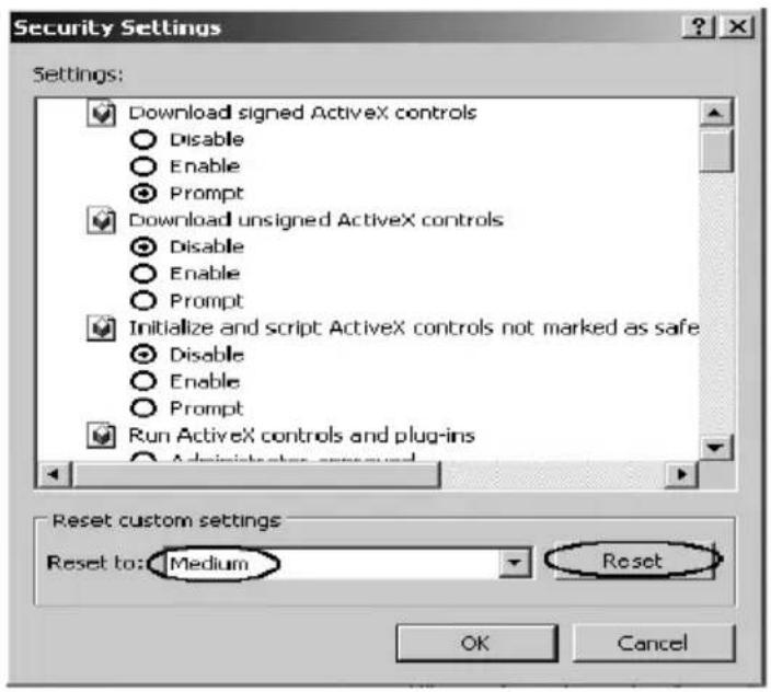
Figure 5-4 Security Settings
Fourthly, select the "Medium" option of the combo box indicated in figure 5-4, click the "Reset" button, and click "OK" to quit.
Fifthly, right-click the mouse on the desktop, select the "Display Properties" in the popup menu, a new dialog will display:
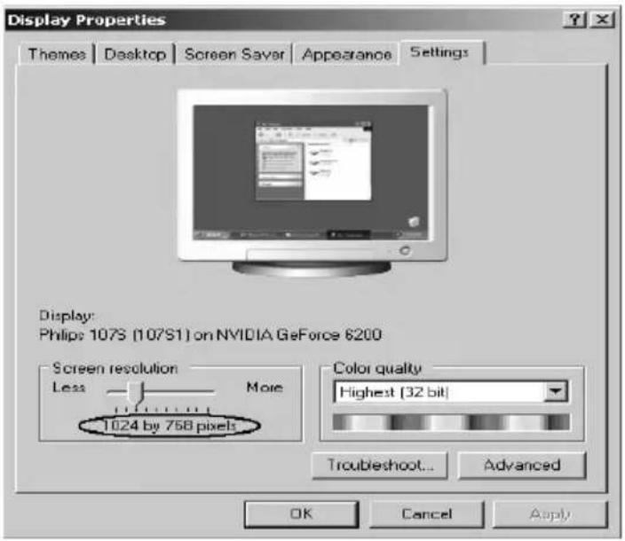
Figure 5-5 Resolution Settings
Click the "Settings" label, set the screen resolution to 1024 x 768 and click "OK". All the necessary IE configuration is completed.
5.2.2 Login the Switch
Supposing the switch IP address is set as 192.168.0.1, open a web browser and enter http://192.168.0.1 in the address location, and then the following dialog page appears:

Figure 5-6 Login Dialog
Enter username and password (default value are both "supervisor") to login the switch configuration main page.
5.3 Setting the Device
After logging into the switch, the main page appears as the following. It contains three parts:
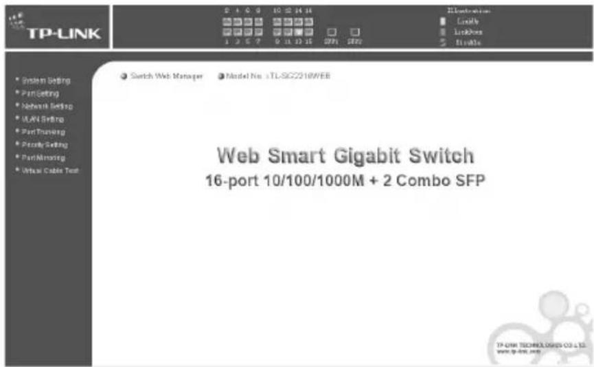
Figure 5-7 TL-SG2216WEB Main Page
1) The main part of the page is the main window to display the configuration page. 2) The Port Led Indicator table lies at the top of the page. It provides a visual representation of the ports on the switch front panel to display the status of the ports. The ports, signed with number are the Giga ports, signed with SFP are the SFP ports. The green icon indicates that the port is linked; the gray icon indicates that the port is not linked; the gray icon with a black bar indicates that the port is disabled; for the SFP port, the blue icon indicates that the SFP module hasn't been installed.

Figure 5-8 Port Led Indicator Table (SFP uninstalled)
Figure 5-9 Port Led Indicator Table (SFP installed)
Click on the icon of the port to open a new window, which shows the details status of the port, as following:
| Port ID: | 1 |
| Port Status: | Linkup |
| Port Speed: | 1000Mbps |
| Duplex Mode: | FD |
| Flow Control: | Disable |
Figure 5-10a Port Status Table
| Port ID: | SFP1 |
| Port Status: | - |
| Port Speed: | - |
| Duplex Mode: | - |
| Flow Control: | - |
| Moudle Type: | Not install |
Figure 5-10b SFP Status Table (uninstalled)
| Port ID: | SFP1 |
| Port Status: | Linkup |
| Port Speed: | 1000Mbps |
| Duplex Mode: | FD |
| Flow Control: | Disable |
| Moudle Type: | Company: TP-LINK Model: TL-SM311LM |
Figure 5-10c SFP Status Table (installed)
On the left side of the page is the menu table. It contains 8 main menus. Each menu has a submenu. Click on a menu, it will open its submenu and the main window displays the configuration page of the submenu list first, click on the submenu you want to configure to open the corresponding configuration page. The menu structure is as follows:

Figure 5-11 Main Menu
System Setting: System Information, File Transfer, Reboot & Reset, and User. ➢ Port Setting: Port Parameter, Port Statistic, Port Status, Storm Control, and Port Description. Network Setting: Switch IP Address, Static MAC Address, Filtering MAC Address, Dynamic Binding, Bound MAC Address, Aging Time, and Ping. ➢ VLAN Setting: VLAN Mode, Port VLAN Setting, Tag VLAN Global Setting, Tag VLAN Setting, MTU VLAN Setting. Port Trunking: Port Trunking. ➢ Priority Setting: Priority Mode, Port-Based Priority, Port Default Priority, 802.1p Priority Class. ➢ Port Mirroring: Port Mirroring. ➢ Virtual Cable Test: Virtual Cable Test.
The following shows main page of the TL-SG2224WEB:

Figure 5-12 TL-SG2224WEB Main Page
5.3.1 System Setting
System setting contains four topics: system information, file transfer, reboot & reset and user.
5.3.1.1 System Information
This page contains the following fields:

Figure 5-13 System Information
Software Version: Displays the installed software version number. ➢ Hardware Version: Displays the installed device hardware version number. System Description: Displays the device model number and name. System Name: Defines the user-defined device name. System Location: Defines the location where the system is currently running. Contact Information: Defines the contact information of switch manager. ➢ Run time: Shows the run time since last startup.
5.3.1.2 File Transfer
This page contains the following fields:

Figure 5-14 File Transfer
➢ Transfer Type: Lists three types of file transfer supported by the switch.
File Name: Identifies the file to be loaded or to be backed up on TFTP server. ➢ TFTP Server IP: Indicates the IP address of TFTP server.

Further explanation
File transfer types:
System Upgrading: Means downloading the executable file from TFTP server to switch and upgrading the system.
Configuration Backup: Means backing up the current configuration of the switch to TFTP server. Configuration Loading: Means downloading the configuration from TFTP server to the switch and update it.

Notice:
1) Please make sure the target file exists on TFTP server before downloading. 2) Please make sure the TFTP server is in operation. 3) Breaks should be avoided in file transfer; otherwise, the switch may be damaged.
This page is shown below.

Figure 5-15 Reboot & Reset
A prompt will display if a button is pressed. For example, if the button "Soft-reset" is pressed, a message box will be activated as shown in figure 5-16.

Figure 5-16 Message Box
5.3.1.4 User
This page provides the interface for configuring username and password.
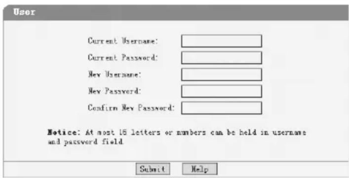
Figure 5-17 User Configuration
You are kindly suggested to retype the new password in the "Confirm new password" box instead of copying it, in order to avoid mistakes.

Notice:
1) Only letters, numbers, and punctuation can be entered into the username and password fields; other characters are considered illegal. The length of the username and password ranges from 1 to 16 characters. 2) The initial username and password are supervisor/supervisor.
5.3.2 Port Setting
5.3.2.1 Port Parameter
This page contains the following fields:

Figure 5-18 Port Parameter
Port Status: Indicates whether the port is operational or non-operational. "Enable" indicates that the port is operational, and "Disable" indicates the port is non-operational. If a port is unused for a long time, it can be set to non-operational to reduce energy costs.

Notice:
1) You cannot manage the switch via a port that is non-operational; please set the value of the management port to "Enable". 2) SFP ports are combo ports sharing a connection with a Gigabit port. In TL-SG2216WEB, SFP1 and port 15 compose a combo port, SFP2 and port 16 compose a combo port; in TL-SG2224WEB, SFP1 and port 23 compose a combo port, SFP2 and port 24 compose a combo port. For a
combo port, only one operation type can be active at a time. If both ports are connected at the same time, the SFP port has priority to be active. The combo port uses the same configuration. For example, in TL-SG2216WEB, if port 15 is active and the Port Status parameter is set to "Disable", when SFP1 is active, its Port Status parameter will also be "Disable".
Port Security: "Enable" indicates that the port will not learn new MAC addresses and will only transmit frames from the MAC addresses it has already learned. "Disable" indicates that it will learn new MAC addresses.

Notice:
If you have not set static MAC addresses, you cannot set all ports' security to enabled, as this would prevent you from managing the switch.
Flow Control: Indicates whether flow control is enabled or disabled.

Notice:
If the port is working at half duplex, the settings of flow control are divided into several groups (each group includes 6 ports), for example, port 1 to 6 are assigned to group 1. The ports of the same group share the same flow control settings, so when you modify the setting of one port, those of the other ports are changed correspondingly.
Duplex Mode: Possible field values are Auto, 10M HD, 10M FD, 100M HD, 100M FD and 1000M FD. "HD" stands for half-duplex and "FD" stands for full-duplex. "Auto" means auto negotiation.

Notice:
Though the SFP module supports hot-plugging, the configuration of Duplex Mode cannot change automatically. After switching between UTP, 100M SFP and 1000M SFP on the combo port, please modify its Duplex Mode manually or re-electrify the switch to make sure the configuration is correct. The 100M SFP should be set to "100M FD" and the 1000M SFP should be set to "AUTO" or "1000M FD".

Further explanation:
1) By operating on fields in the All Ports line expediently, you can set the values of all ports in the corresponding field. Some other setting pages offer the same function. 2) Parameters of Trunk member ports are configured with default values (see the Appendix B table) and cannot be configured here (see port 5 and 6 in the figure for example).
5.3.2.2 Port Statistic
This page displays the port statistic. It contains the following entries:

Figure 5-19 Port Statistic
Tx Collisions: The number of collision events seen by the MAC. This counter is applicable in half-duplex only. Tx Ucast: The number of frames sent that have a unicast destination MAC address. Tx Mcast: The number of frames sent that have a multicast destination MAC address. Tx Bcast: The number of frames sent that have a broadcast destination MAC address. Rx (G Pkts): The number of good frames received. Rx Ucast: The number of frames received that have a unicast destination MAC address. Rx Mcast: The number of frames received that have a multicast destination MAC address. Rx Bcast: The number of frames received that have a broadcast destination MAC address. Rx (B Bytes): The sum of bytes of frames received with an invalid length. The frames with the length more than 1522 octets are counted as 1522 octets ones. Rx UnderSz: Total frames received with a length of less than 64 octets but with a valid FCS. Rx OverSize: Total frames received with a length of more than max size octets but with a valid FCS. Rx Jabber: Total frames received with a length of more than max size octets but with an invalid FCS. ➢ 64 B: Total frames received and transmitted with a length of exactly 64 octets, including those with errors. ➢ 65 to 127 B: Total frames received and transmitted with a length of
between 65 and 127 octets inclusive, including those with errors.
128 to 255 B: Total frames received and transmitted with a length of between 128 and 255 octets inclusive, including those with errors. 256 to 511 B: Total frames received and transmitted with a length of between 256 and 511 octets inclusive, including those with errors. 512 to 1023 B: Total frames received and transmitted with a length of between 512 and 1023 octets inclusive, including those with errors. RX Bytes: The sum of bytes of frames received, not including those with errors.

Notice:
Each statistic counter has a maximum numerical value of about 1.8e+19. If this value is exceeded, the counter will reset to zero. You can also click the "Reset" button to reset all statistic counters to zero.
5.3.2.3 Port Status
This page displays the port status. It contains the following fields:
| Refrash | ||||
| Port | Port Status | Speed (Wbps) | Duplex Mode | Flow Control |
| 1 | Linkdown | - | - | - |
| 2 | Linkup | 1000 | Full Duplex | Disable |
| 3 | Linkup | 1000 | Full Duplex | Disable |
| 4 | Linkup | 1000 | Full Duplex | Enable |
| 5 | Linkup | 1000 | Full Duplex | Enable |
| 6 | Linkup | 1000 | Full Duplex | Enable |
| 7 | Linkup | 1000 | Full Duplex | Disable |
| 8 | Linkup | 1000 | Full Duplex | Disable |
| 9 | Linkup | 1000 | Full Duplex | Enable |
| 10 | Linkup | 1000 | Full Duplex | Enable |
| 11 | Linkup | 1000 | Full Duplex | Enable |
| 12 | Linkup | 1000 | Full Duplex | Disable |
| 13 | Linkup | 1000 | Full Duplex | Disable |
| 14 | Linkup | 1000 | Full Duplex | Enable |
| 15 | - | - | - | - |
| 16 | Linkup | 1000 | Full Duplex | Enable |
| SPT1 | Linkup | 1000 | Full Duplex | Disable |
| SFP2 | - | - | - | - |
Figure 5-20 Port Status
➢ Port Status: Indicates whether the port is linked, not linked, or disabled. ➢ Speed (Mbps): Indicates the port speed in Mbps. Duplex Mode: Indicates the port duplex mode. ➢ Flow Control: Indicates whether flow control of the port is enabled or disabled.
5.3.2.4 Storm Control
This page contains the following fields:

Figure 5-21 Storm Control
➢ Broadcast Control: Enable or disable broadcast control to limit broadcast frames. Ports belonging to the same Trunk should have the same value. Multicast Control: Enable or disable multicast control to limit multicast frames. Enabling multicast control will also enable broadcast control. All ports share the same setting. UL Control: Enable or disable UL control to limit UL packets. Enabling UL control will also enable broadcast control and multicast control. All ports share the same setting. Limit Rate: Indicates the maximum rate (frames per second) at which the controlled packets configured above are forwarded. For UL control, the unit is kilo frames per second, and the statistic is the sum of all ports. All ports share the same setting.
5.3.2.5 Port Description
This page configures the description to indicate the ports.
Input description words in the Description field for each port. Note that each field can hold at most 15 letters or numbers.

Figure 5-22 Port Description
5.3.3 Network Setting
This page contains the following topics: switch IP address, static MAC address, filtering MAC address, dynamic binding, bound MAC address, aging time, and ping.
5.3.3.1 Switch IP Address
This page is shown below:

Figure 5-23 Switch IP Address
MAC Address: Is fixed into the switch during the manufacturing process; it is unique and unchangeable.
DHCP Client: Indicates whether the DHCP function is enabled. If DHCP client is enabled, the switch will obtain the IP address, netmask, and default gateway from the DHCP server automatically; otherwise, these three items should be configured manually. IP Address: Is necessary for switch management. The configuration of the switch IP address must be compliant with the subnet layout. Default Gateway: Serves as the default destination when a packet whose destination IP address is not within the switch's subnet is to be forwarded.

Notice:
1) When DHCP client is enabled, the IP parameters are obtained automatically from the DHCP server, so the "IP Address", "Netmask", and "Default Gateway" fields are disabled. These parameters can be queried on the DHCP server. 2) The initial state of the DHCP client is disabled and the initial IP address is 192.168.0.1.
5.3.3.2 Static MAC Address
This page provides the function of adding, searching a static MAC address, and changing the entry state, as shown in Figure 5-24.
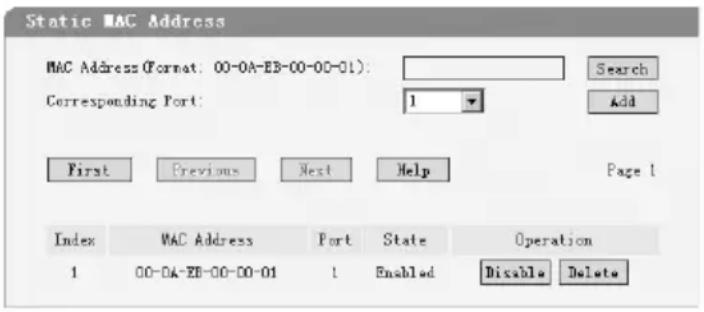
Figure 5-24 Static MAC address
A MAC address and its corresponding switch port should be provided when adding a static MAC address entry.
➢ Search: Input the MAC address in the "MAC Address" field and click the "Search" button. If that MAC address exists, the following page will display:
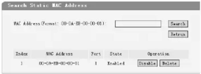
Figure 5-25 A Successful Search
Index: Stands for entry index of the MAC address in the table. Port: Stands for the switch port number. State: Indicates the entry in enabled state or disabled state. Operation: Provides the function of enabling, disabling or deleting an entry. Return: Return to the "Static MAC Address" page.
A search can also be executed in this page.
If the static MAC address isn't found in searching, then the following page will display:

Figure 5-26 A Failed Search
Add: Input the MAC address in the "MAC Address" field and select a port number in "Corresponding Port" combo box, click the "Add" button, that MAC addresses may be added to the static MAC address table if the following conditions are met:
1) That MAC address doesn't exist in static MAC address; 2) That MAC address doesn't exist in filtering MAC address; 3) There is enough space in static MAC address table (the capacity of the static MAC address table is shown in "Appendix C").
The static MAC address table is divided into several pages. At most 10 entries can be held in on page. The buttons "First", "Previous" and "Next" can be used to browse the whole table.

Notice:
1) The capacity of the static MAC address is showed in "Appendix C". 2) If an incorrect port number is selected when adding an entry, or the port number is modified unexpectedly later, then the entries must be renewed; otherwise, the packets cannot be forwarded correctly. 3) If a device, whose MAC address is added to static MAC address table, is connected to a wrong switch port (not the port configured in static MAC address entry), all the packets routing to the device cannot reach the device. 4) A MAC address cannot be added to static MAC address table and filtering MAC address table simultaneously.
5.3.3.3 Filtering MAC Address
All the packets taking the filtering MAC address as their destination are
discarded by the switch no matter which port they enter from.
This page provides the function of adding, searching a filtering MAC address and changing the entry state. The filtering MAC address entry is applicable to all switch ports. The operating instruments, which are similar to "Static MAC Address", are omitted here.
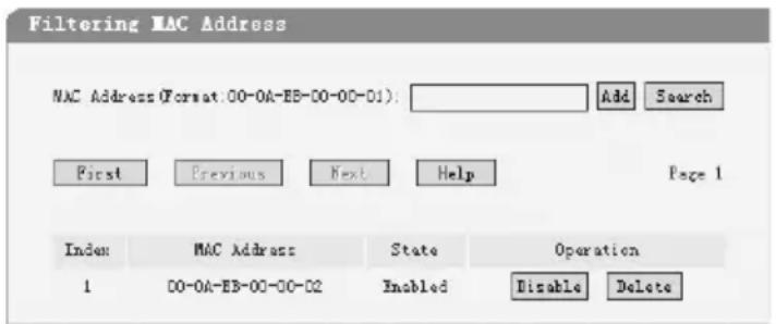
Figure 5-27 Filtering MAC Address
Index: Indicates the entry index of filtering MAC address table. MAC Address: Indicates the filtering MAC address to be configured or to be searched. State: Indicates the entry in enabled state or disabled state.

Notice:
The capacity of filtering MAC address table is showed in "Appendix C".
5.3.3.4 Dynamic Binding
This page provides the function of enabling or disabling dynamic binding.
If dynamic binding is disabled, the switch port learns MAC address unlimitedly (at most 8000 entries can be learned actually).
A switch port with dynamic binding enabled can bind a specified number of
MAC addresses. The MAC addresses bound by the switch port are always valid and won't age. If the specified number is reached, the port stops binding and transfers into secure state.
The bound MAC addresses can be queried in the "Bound MAC Address" page.
If the dynamic binding is disabled or the switch restarts, the bound MAC address entries are cleared.
There are 5 items in this page:

Figure 5-28 Dynamic Binding
➢ Port: Indicates switch port number.
Binding: Three options are available. A further explanation is stated below. Number of MAC Address to Bind: Indicates the max number of MAC addresses that one switch port can bind. ➢ Number of Bound MAC Address: Indicates the number of MAC addresses that already bind to a switch port. State: Indicates the switch port state that may be binding, free port, secure port, unplugged or "--". A further explanation is stated below.

Further explanation
Options of dynamic binding:
1) Disable: Cause this port to learn MAC address freely. 2) Enable: Cause the port to bind MAC addresses until the specified number is reached. 3) --: This option is available only if the port is in secure state, when this option is selected, the port state keeps unchanged.
Port states:
1) Free Port: The binding function is disabled, and the port can learn MAC address freely. 2) Binding: The port is in binding state, and its bound MAC address number is still less than the max number. 3) Secure Port: The port has already bound the max number of MAC address in dynamic binding mode, or it was set to secure port manually in "Port Parameter" page. 4) Unplugged: The port is a SFP port and unplugged yet. The dynamic binding function cannot be configured now. 5) --: The port is a trunk member and its binding function cannot be configured.

Further Explanation
1) If the port is set to secure port manually in "Port Parameter" page, the dynamic binding cannot be configured here. If the port with dynamic binding enabled transfers into secure state automatically because the port has bound the specified number MAC address, the dynamic binding function of the port can be enabled or disabled again. 2) The combo box in "All Ports" entry is used to change the selections of corresponding combo boxes of all ports simultaneously. 3) A "Refresh" button is provided to look up the latest number of bound MAC address.

Notice:
If the switch port is a trunk member or an unplugged SFP port, the binding function of the port cannot be configured here.
5.3.3.5 Bound MAC Address
This page is showed as below:

Figure 5-29 Bound MAC Address
Index: Indicates the entry index in dynamic binding MAC address table. MAC Address: Indicates MAC address already bound to the switch ports. ➢ Port: Indicates the switch port number corresponding to the bound MAC address.

Further Explanation
1) The bound MAC address table contains all the MAC addresses bound by the switch ports. Every entry contains one MAC address and its corresponding port number. 2) The bound MAC address table is divided into several pages. At most 10 entries can be held in one page. The buttons "First", "Previous" and "Next" can be used to browse the whole table.
5.3.3.6 Aging Time
This page is showed as below:

Figure 5-30 Aging Time
Aging Time (0~630): When a new MAC address is learned by the switch, it is added to the dynamic MAC address table and a relative timer is generated immediately. If no packet with that MAC address as its source passes through the switch within a specified time, the MAC address is removed from the table. This process is called "aging," and the specified time is called "aging time."

Further Explanation
1) The aging time ranges from 0 to 630 seconds. An appropriate aging time should be configured. An aging time that is too long delays the deletion of dynamic MAC addresses, which can cause incorrect packet forwarding. An aging time that is too short causes table entries to be deleted quickly, and some packets must be broadcast because no corresponding entries are available. This reduces forwarding efficiency.
If the dynamic MAC address is deleted too early, packets may be forwarded incorrectly. If the aging time is too short, table entries are deleted quickly, and some packets must be broadcast because no corresponding entries are available, reducing forwarding efficiency.
2) The MAC addresses in the static MAC address table, filtering MAC address table, and bound MAC address table are not subject to aging time.
The ping function tests the connectivity of the link between the switch and the destination. This page is shown below:
The ping function is used to test the connectivity of the link between the switch and the destination. This page is shown below:

Destination IP Address: Indicates the IP address of the test destination. Ping Count: Indicates the number of ping attempts in one submission. Data Size: Indicates the data field length of the ping packet. Ping Interval: Indicates the time interval between two consecutive pings.
Destination IP Address: Indicates the IP address of the test destination. Ping Count: Indicates the number of ping times in one submission. Data Size: Indicates the data field length of the ping packet. Ping Interval: Indicates the time interval between two consecutive pings.
5.3.4.1 VLAN Mode
This page selects the VLAN mode. Possible field values are:
This page selects the VLAN Mode. Possible field values are:

VLAN Disable: No VLAN is set on the switch; all ports can communicate with each other. Port VLAN (Port-Based VLAN): Sets Port-Based VLAN mode. Tag VLAN (802.1Q Tag VLAN): Sets 802.1Q Tag VLAN mode. MTU VLAN: Sets MTU VLAN mode. This mode cannot be set if any Trunk has been configured.
VLAN Disable: Do not set any VLAN in the switch, all ports of the switch can communicate with each other. Port VLAN (Port-Based VLAN): Set the Port-Based VLAN mode. Tag VLAN (802.1Q Tag VLAN): Set the 802.1Q Tag VLAN mode. MTU VLAN: Set the MTU VLAN mode. This mode cannot be set if any Trunk has been set.
5.3.4.2 Port VLAN Setting
This page displays when the switch is in Port VLAN mode. It contains the following fields:

Figure 5-33 Port VLAN Setting
VLAN: The VLAN number. Select the number of the VLAN you want to configure here. ▶ Port: The switch port number. ➢ Member: Select the member of the VLAN here. If this field is checked, it indicates the port belongs to the current VLAN. ➢ Description: Displays the user-defined port description. All VLAN: Displays all defined Port VLANs.

Figure 5-34 All Port VLAN
Select All: Select all ports to be VLAN members. Clean Up: Clean up all members of the VLAN. Submit: Submit to build up a VLAN with the selected members.

Notice:
1) Any VLAN cannot be the subset or superset of other VLANs. 2) At least two port members should be included to add a VLAN group. (If the page is submitted with 0 VLAN member, it indicates to delete the VLAN.) 3) If any Trunk has been set, the Trunk can be configured as a VLAN member, and the member ports of the Trunk cannot be configured (see Port 1 and 2 in the figure for example). 4) For the first time the Port VLAN mode is set, a default VLAN, which is indexed as NO. 1 and contains all switch ports, will be built up. 5) The ports haven't been assigned to any VLAN manually will be assigned to a hidden VLAN automatically to make sure they can communicate with
each other.
6) The number of Port VLANs that can be set is the same as the switch port number.
5.3.4.3 Tag VLAN Global Setting
This page displays when the switch is in Tag VLAN mode. The global setting of the ports will affect all Tag VLANs. It contains the following fields:

Figure 5-35 Tag VLAN Global Setting
Port: The switch port number. ➢ PVID: While receiving an untagged frame from the port, the switch will assign a tag to the frame, using the PVID of the port as its VID. Untag Frame: The solution to the untagged frame received. "Drop" will drop the frame and "Pass" will transmit the frame in the VLAN with the VID the same as the PVID of the port. All Ports: By operating on this field expediently, you can set the values of all ports in the corresponding field.

Notice:
If any Trunk has been set, the Trunk can be configured, but member ports of the Trunk cannot be configured, and in the fields it displays the parameters of the Trunk they belong to (see port1 and 2 in the figure for example).
5.3.4.4 Tag VLAN Setting
This page displays when the switch is in Tag VLAN mode. It configures each VLAN and is affected by the global setting of the ports. It contains the following fields:

Figure 5-36 Tag VLAN Setting
VLAN: The VLAN number. Select the number of the VLAN you want to configure here.
▶ VLAN ID: Configure the VLAN ID. ▶ Port: The switch port number. ➢ Member: Select the member of the VLAN here. If this field is checked, it indicates that the port belongs to the current VLAN. ➢ Egress Frame: The solution to the egress frame. "Drop Tag" indicates drop the tag header before sending the frame. "Add Tag" indicates add the tag header before sending the frame. ➢ Description: Display the user-defined port description. All Ports: By operating on this field expediently, you can set the values of all ports in the corresponding field. All VLAN: Display all defined Tag VLANs.

Figure 5-37 All Tag VLAN
Select All: Select all ports to be VLAN members. Clean Up: Clean up all members of the VLAN. Submit: Submit to build up a VLAN with the selected members.

Notice:
1) VID of the VLAN must be unique and within the range of 1 to 4094. 2) At least two port members should be included to add a VLAN group. (If the page is submitted with 0 VLAN member, it indicates to delete the VLAN.) 3) If any Trunk has been set, the Trunk can be configured as a VLAN member and member ports of the Trunk cannot be configured (see Port 1 and 2 in the figure for example).
4) If the port is connected to a device that doesn't support IEEE802.1Q (e.g. HUB and some network adapter), value of the Egress Frame field should be set to "Drop Tag". 5) For the first time the Port VLAN mode is set, a default VLAN, which is indexed as NO. 1 and contains all switch ports, will be built up. 6) The ports haven't been assigned to any VLAN manually cannot communicate with each other or other VLAN. That's different from the Port VLAN. 7) The number of Port VLAN can be set depends on the switch type. See the Appendix C for details.
5.3.4.5 MTU VLAN Setting
This page, which is designed to configure the uplink port, displays when the switch is in MTU VLAN mode.

Figure 5-38 MTU VLAN Setting

Notice:
1) The uplink port will build up several VLANs with each of the other ports. Each VLAN contains two ports: the uplink port and one of the other ports in the switch, so the uplink port can communicate with any other port, but other ports can't communicate with each other. 2) The first time the MTU VLAN mode is set, it sets port 1 to be the uplink port by default.
5.3.5 Port Trunking
This page contains the following fields:

Figure 5-39 Port Trunking
Trunk: The Trunk number. ➢ Member: Select the member of the Trunk here. Each group has 4 optional ports to compose a Trunk. Select All: Select all Trunk members in the list. Clean Up: Clean up the Trunk member list.

Notice:
1) Each Trunk should contain 2 to 4 ports (If a Trunk is submitted with 0 member port, it indicates to delete the Trunk). 2) Trunks cannot be set if the switch is in MTU VLAN mode.
5.3.6 Priority Setting
Priority setting contains four topics: priority mode, port-based priority, port default priority and 802.1p priority.
Because dynamic menu is adopted, only the pages corresponding to current priority mode are revealed. If the parameters of other priority mode are to be configured, select the corresponding priority mode in “Priority Mode” page first.
5.3.6.1 Priority Mode
This page is showed as below:
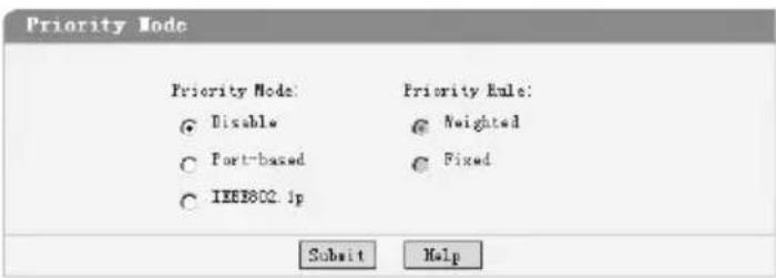
Figure 5-40 Priority Mode
➢ Priority Mode: Contains "Disable", "Port-Based" and "IEEE802.1p". ➢ Priority Rule: Contains “Weighted” and “Fixed”. If the priority mode is set to “Disable”, the priority rule cannot be configured.
5.3.6.2 Port-Based Priority
This page is revealed when the "Port-Based" mode is configured. As shown below:
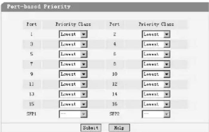
Figure 5-41 Port-Based priority
Port: Indicates the switch port number. Priority Class: In port-based priority mode, the switch ports are classified into four priority classes: lowest, lower, higher, and highest. All the packets
entering from the port of the switch are forwarded in the corresponding priority queue.

Further Explanation
When priority rule is configured as "weighted", a 1,2,4,8 weighting is applied to forward these four classes of packets.
5.3.6.3 Port Default Priority
This page is revealed when the "IEEE802.1p" mode is configured. When a switch port receives an untagged frame (a frame without priority tag), the port's default priority tag will be inserted into the frame before any other process.

Figure 5-42 Port Default Priority
Port: Indicates the switch port number. Default Priority Tag: Indicates 802.1p tag being inserted into untagged frames.
5.3.6.4 802.1p Priority Class
This page is revealed when the "IEEE802.1p" mode is configured. As shown below:

Figure 5-43 802.1p Priority
Priority Tag: The priority tag defined in IEEE802.1p. Corresponding Priority Class: Indicates the inner priority classes of switch. The tagged frames are classified into four classes inside the switch: lowest, lower, higher, and highest. When the "Weighted" priority rule is configured, a 1,2,4,8 weighting is applied to forward these four classes of packets.

Further explanation
In IEEE802.1p priority mode, when a switch port receives an untagged frame (a frame without priority tag), the port's default priority tag will be inserted into the frame before any other process.
5.3.7 Port Mirroring
This page contains the following fields:

Figure 5-44 Port Mirroring
➢ Mirror Mode: You can set the mirror mode to monitor the ingress traffic, egress traffic, or both traffic. You can also disable the port mirroring. ➢ Mirror Port: Defines the port to monitor the traffic, Trunk member can't define here. Mirrored Port: Indicates the port from which the packets are mirrored, Trunk member can't define here. At most 4 ports can be mirrored simultaneously. Clean Up: Clean Up the Mirrored Port list.

Notice:
1) Trunk member port can be neither Mirror Port nor Mirrored Port. 2) The Mirror Port can't be the Mirrored Port at the same time. 3) At most 4 Mirrored Ports can be set. 4) If a 100M SFP module is installed, it can't be the Mirror Port. If it has been configured as the Mirror Port before, please modify it.
5.3.8 Virtual Cable Test
The virtual cable test feature lets you test the continuity of the cable circuit. It contains the following fields:

Figure 5-45 Virtual Cable Test
Test Port: Select the port you want to test.
- Link Status: Reports good status or issues such as cable opens, cable shorts or any impedance mismatch in the cable. ➢ Link Length: Reports the range of the cable length if the link status is good. Fault Distance: Reports the distance to the open/short location. Test: Test the cable via the selected port.

Notice:
Cable connected to the SFP cannot be tested.
Appendix A Pin Explain For RJ-45 Connector
The switching port can connect to stations wired in standard RJ-45 Ethernet station mode using straight cables. Transmission devices connected to each other use crossed cables. The following figure illustrates the pin allocation:
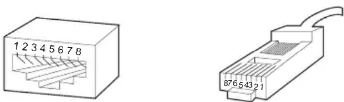
Figure RJ-45 connector. The following shows the way to make the cable used to connect switch to network adapter, and cable used to connect switch to switch/hub/bridge.
| Pin signal allocation for RJ-45 connector | ||
| Pin MDI-II | MDI-X | |
| 1 TX+ (send) | RX+ (receive) | |
| 2 TX- (send) | RX- (receive) | |
| 3 RX+ (receive) | TX+ (send) | |
| 4 No use No | use | |
| 5 No use No | use | |
| 6 RX- (receive) | TX- (send) | |
| 7 No use No | use | |
| 8 No use No | use | |
Straight cable: used to connect switch (uplink port) or network adapter to switch/hub/other device (normal port).
![graph LR subgraph MDI-II A1["1 TX+"] --> A2["2 TX-"] A3["3 RX+"] --> A4["6 RX-"] end subgraph MDI-X B1["1 RX+"] --> B2["2 RX-"] B3["3 TX+"] --> B4["6 TX-"] end A1 --> B1 A2 --> B2 A3 --> B3 A4 --> B4 B1 --> C1["Output"] B2 --> C2["Output"] B3 --> C3["Output"] B4 --> C4["Output"]](/content/2026/06/1345813/images/d3acd408b789577195cf50675954fa7908e19b04861b1b7a7f7270d12771f270.jpg)
Figure straight cable
Crossed cable: used to connect switch (normal port) to switch/hub/other device (normal port).
![graph LR subgraph Left A1["1 RX+"] --> A2["2 RX-"] A3["3 TX+"] --> A4["6 TX-"] end subgraph Right B1["1 RX+"] --> B2["2 RX-"] B3["3 TX+"] --> B4["6 TX-"] end A1 --> B1 A2 --> B2 A3 --> B3 A4 --> B4 A5 --> B5 B1 --> C1["MDI-XMDI-X"] B2 --> C2["MDI-XMDI-X"] B3 --> C3["MDI-XMDI-X"] B4 --> C4["MDI-XMDI-…](/content/2026/06/1345813/images/576270f4bdcaef479662c42676d8723d453bafe82701858708ec5b77261e9798.jpg)
Figure crossed cable
Appendix B Table of Factory Defaults
Table of Factory Defaults:
| System Setting | System Information | System Name Null | |
| System Location Null | |||
| Contact Information Null | |||
| File Transfer | Transfer Type System Upgrading | ||
| File Name | SysSG2216WEB.bin | ||
| User | User Name supervisor | ||
| Password supervisor | |||
| Port Setting | Port Parameter | Port Status Enable | |
| Port Security Disable | |||
| Flow Control Disable | |||
| Duplex Mode Auto | |||
| Port Statistic All 0 | |||
| Storm Control | Broadcast Control | Disable | |
| Multicast Control Disable | |||
| UL Control | Disable | ||
| Limit Rate | 64K | ||
| Port Description | Null | ||
| Network Setting | Switch IP Address | DHCP client | Disable |
| IP Address | 192.168.0.1 | ||
| Netmask | 255.255.255.0 | ||
| Default Gateway Null | |||
| Static MAC Address | Null | ||
| Filtering MAC Address | Null | ||
| Dynamic Binding | Binding | Disable | |
| Number of MAC Address to Bind | 5 | ||
| Bound MAC Address | Null | ||
| Network Setting | Aging Time Aging Time | 300 | |
| Ping | Destination IP Address | 192.168.0.1 | |
| Ping Count 4 | |||
| Data Size 64 | |||
| Ping Interval 1000 | |||
| VLAN Setting | VLAN Mode Disable | ||
| Port VLAN Setting All ports belong to VLAN 1 | |||
| Tag VLAN | PVID 1 | ||
| Global Setting | Untag Frame Pass | ||
| Tag VLAN Setting | All ports belong to VLAN 1; the VID is 1 and “Egress Frame” is "Drop Tag" | ||
| MTU VLAN Setting Up link port 1 | |||
| Port Trunking No configured Trunk | |||
| Priority Setting | Priority Mode | Priority Mode Disable | |
| Priority Rule | Weighted | ||
| Port-Based Priority | Priority Class Lowest | ||
| Port Default Priority | Port Default Priority Tag | 0 | |
| 802.1P Priority | Priority Tag 0,1 | Lowest | |
| Priority Tag 2,3 | Lower | ||
| Priority Tag 4,5 | Higher | ||
| Priority Tag 6,7 | Highest | ||
| Port Mirroring | Port Mirroring | Mirror Mode | Disable |
| Mirror Port | 1 | ||
| Mirrored Port | Null | ||
Appendix C Table of Function Differences of Switch Family
Table of Function Differences of Switch Family
| Function | Models | |
| TL-SG2216WEB TL-S | G2224WEB | |
| Port 16 24 | ||
| Giga Port 16 24 | ||
| SFP Port 2 2 | ||
| Trunk 4 6 | ||
| Port VLAN 16 24 | ||
| Tag VLAN 256 256 | ||
| Static MAC | 128 128 | |
| Filtering MAC | 128 128 | |
| Dynamic Binding MAC | 192 240 | |
| Power Consumption | 35W MAX | 35W MAX |


TP-LINK®
TP-LINK TECHNOLOGIES CO., LTD.
E-mail: support@tp-link.com
Website: http://www.tp-link.com
Add: Fl.3, Bldg.R1-B, High-Tech Industrial Park, Shenzhen Road, Shenzhen, China




- COPYRIGHT & TRADEMARKS
- FCC STATEMENT
- EC DECLARATION OF CONFORMITY (EUROPE)
- SAFETY NOTICES
- CAUTION
- TABLE OF CONTENTS
- PACKAGE CONTENTS
- CHAPTER 1: INTRODUCTION
- CHAPTER 2: DEVICE DESCRIPTION
- CHAPTER 3: MOUNTING DEVICE
- CHAPTER 4: FUNCTION DESCRIPTION
- CHAPTER 5: WEB MANAGEMENT
- APPENDIX A PIN EXPLAIN FOR RJ-45 CONNECTOR
- APPENDIX B TABLE OF FACTORY DEFAULTS
- APPENDIX C TABLE OF FUNCTION DIFFERENCES OF SWITCH FAMILY
- NOTE
- INTENDED AUDIENCE
- AGREEMENT
- GUIDE OVERVIEW
- INTRODUCTION TO THE DEVICE
- FEATURES AND TECHNICAL SPECIFICATIONS
- FEATURES
- M
- TECHNICAL SPECIFICATIONS
- INSTALL THE DEVICE
- DESKTOP OR SHELF INSTALLATION
- RACK INSTALLATION
- AC POWER
- SWITCH ASPECT DESCRIPTION
- FRONT PANEL
- BACK PANEL
- SFP MODULE
- SYSTEM SETTING
- SYSTEM INFORMATION
- FILE TRANSFER
- REBOOT & RESET
- USER
- PORT SETTING
- PORT PARAMETER
- DUPLEX MODE
- FLOW CONTROL
- PORT SECURITY
- PORT STATISTIC AND PORT STATUS
- STORM CONTROL
- PORT DESCRIPTION
- NETWORK SETTING
- SWITCH IP ADDRESS
- NOTICE
- AGING TIME AND DYNAMIC ADDRESS TABLE
- STATIC MAC ADDRESS TABLE
- FILTERING MAC ADDRESS TABLE
- DYNAMIC BINDING
- PING
- VLAN SETTING
- VLAN MODE
- PORT VLAN
- IEEE802.1Q TAG VLAN
- MTU VLAN
- PORT TRUNKING
- PRIORITY SETTING
- PRIORITY MODE
- PORT-BASED PRIORITY
- PORT DEFAULT PRIORITY
- P PRIORITY
- PORT MIRRORING
- VIRTUAL CABLE TEST
- OVERVIEW
- CONNECTING TO THE DEVICE
- GETTING STARTED
- LOGIN THE SWITCH
- SETTING THE DEVICE
- FURTHER EXPLANATION
- PORT STATISTIC
- PORT STATUS
- STATIC MAC ADDRESS
- FILTERING MAC ADDRESS
- PORT STATES
- BOUND MAC ADDRESS
- AGING TIME
- THE PING FUNCTION TESTS THE CONNECTIVITY OF THE LINK BETWEEN THE SWITCH AND THE DESTINATION. THIS PAGE IS SHOWN BELOW
- THIS PAGE SELECTS THE VLAN MODE. POSSIBLE FIELD VALUES ARE
- PORT VLAN SETTING
- TAG VLAN GLOBAL SETTING
- TAG VLAN SETTING
- MTU VLAN SETTING
- P PRIORITY CLASS
- TP-LINK®
Brand : TP-LINK
Model : TL-SG2224WEB
Category : Network switch