
JetStream L2 Managed TL-SG5428 - Network switch TP-LINK - Free user manual and instructions
Find the device manual for free JetStream L2 Managed TL-SG5428 TP-LINK in PDF.


| Product Type | Managed L2 Gigabit Ethernet Switch |
| Brand | TP-Link |
| Model | JetStream L2 Managed TL-SG5428 |
| Ports | 24 x 10/100/1000 Mbps RJ45, 4 x SFP slots |
| Console Port | 1 x RJ45 console port |
| Performance | Wire-speed switching, non-blocking architecture |
| Management Features | Web GUI, CLI (Telnet/SSH), SNMP, RMON, VLAN, ACL, QoS, IGMP snooping, Link Aggregation (LACP), 802.1x, Dynamic ARP Inspection |
| Power Supply | AC 100-240V, 50/60Hz |
| Power Consumption | Approximately 30W (estimated) |
| Weight | Approximately 5.5 kg (12.1 lbs) |
| Dimensions (W x D x H) | 440 x 220 x 44 mm (17.3 x 8.7 x 1.7 in) - 1U rackmount |
| Operating Temperature | 0°C to 40°C (32°F to 104°F) |
| Storage Temperature | -40°C to 70°C (-40°F to 158°F) |
| Operating Humidity | 10% to 90% RH non-condensing |
| Storage Humidity | 5% to 90% RH non-condensing |
| Standards | IEEE 802.3, 802.3u, 802.3ab, 802.3z, 802.3x |
| LED Indicators | PWR, SYS, 1000Mbps, Link/Act per port |
| Installation | Desktop or 19-inch rack (brackets included) |
| Safety Precautions | Use provided power cord, ensure grounding, wear ESD wrist strap during installation, keep ventilation |
| Cleaning and Maintenance | Power off before cleaning; dust regularly with dry cloth; avoid liquid cleaners |
| Repair and Spare Parts | No user-serviceable parts; contact TP-Link support for service |
| Default IP | 192.168.0.1 |
| Default Username/Password | admin / admin |
Frequently Asked Questions - JetStream L2 Managed TL-SG5428 TP-LINK
User questions about JetStream L2 Managed TL-SG5428 TP-LINK
0 question about this device. Answer the ones you know or ask your own.
Ask a new question about this device
Download the instructions for your Network switch in PDF format for free! Find your manual JetStream L2 Managed TL-SG5428 - TP-LINK and take your electronic device back in hand. On this page are published all the documents necessary for the use of your device. JetStream L2 Managed TL-SG5428 by TP-LINK.
USER MANUAL JetStream L2 Managed TL-SG5428 TP-LINK
Specifications are subject to change without notice. TP-LINK ^® is a registered trademark of TP-LINK TECHNOLOGIES CO., LTD. Other brands and product names are trademarks of their respective holders.
No part of the specifications may be reproduced in any form or by any means or used to make any derivative such as translation, transformation, or adaptation without permission from TP-LINK TECHNOLOGIES CO., LTD. Copyright © 2012 TP-LINK TECHNOLOGIES CO., LTD. All rights reserved.
http://www.tp-link.com
FCC STATEMENT
FC
This equipment has been tested and found to comply with the limits for a Class A digital device, pursuant to part 15 of the FCC Rules. These limits are designed to provide reasonable protection against harmful interference when the equipment is operated in a commercial environment. This equipment generates, uses, and can radiate radio frequency energy and, if not installed and used in accordance with the instruction manual, may cause harmful interference to radio communications. Operation of this equipment in a residential area is likely to cause harmful interference in which case the user will be required to correct the interference at his own expense.
This device complies with part 15 of the FCC Rules. Operation is subject to the following two conditions:
This device may not cause harmful interference.1)
This device must accept any interference received, including interference that may cause undesired operation.2) Any changes or modifications not expressly approved by the party responsible for compliance could void the user's authority to operate the equipment.
CE Mark Warning
CE
This is a class A product. In a domestic environment, this product may cause radio interference, in which case the user may be required to take adequate measures.
Related Document
The User Guide and CLI Reference Guide of the product are provided on the resource CD.
To obtain the latest product information, please visit the Official Website:
http://www.tp-link.com
About this Installation Guide
This Installation Guide describes the hardware characteristics, installation methods and the points that should be attended to during installation.
This Installation Guide is structured as follows:
Chapter 1 Introduction. This chapter describes the External Components of the Switch.
Chapter 2 Installation. This chapter illustrates how to install the Switch.
Chapter 3 Lightning Protection. This chapter illustrates how to prevent lightning damage.
Chapter 4 Connection. This chapter illustrates how to do the physical connection of the Switch.
Chapter 5 Configuration. This chapter instructs you to configure the Switch via Web Interface and CLI commands.
Appendix A Troubleshooting.
Appendix B Hardware Specifications.
Appendix C Technical Support.
Audience
This Installation Guide is for:
Network Engineer
Network Administrator
Conventions
Due to the similarity in the structure of the L2 Managed Switch series, in this Installation Guide we take TL-SG5428 as an example to illustrate Chapter 2 Installation, Chapter 3 Lightning Protection and Chapter 4 Connection.
This guide uses the specific formats to highlight special messages. The following table lists the notice icons that are used throughout this guide.
| Remind to be careful. A caution indicates a potential which may result in device damage. | |
| Remind to take notice. The note contains the helpful information for a better use of the product. |
Contents
Chapter 1 Introduction \_\_\_\_ 01
1.1 Product Overview ....01
1.2 Appearance ....01
Chapter 2 Installation ———— 04
2.1 Package Contents ....04
2.2 Safety Precautions ....04
2.3 Installation Tools ....06
2.4 Product Installation ....06
Chapter 3 Lightning Protection \_\_\_\_ 08
3.1 Cabling Reasonably 08
3.2 Connect to Ground .....10
3.3 Equipotential Bonding .....11
3.4 Use Lightning Arrester .....12
Chapter 4 Connection 13
4.1 Ethernet Port ....13
4.2 SFP Port 13
4.3 Console Port 15
4.4 Verify Installation ....15
4.5 Power On 15
4.6 Initialization ......16
Chapter 5 Configuration ———— 17
5.1 Configure the Switch via GUI ....17
5.2 Configure the Switch Using CLI ....18
Appendix A Troubleshooting — 22
Appendix B Hardware Specifications — 23
Appendix C Technical Support — 24
IntroductionChapter 1
Product Overview1.1
TL-SG5428 and TL-SG5412F are Gigabit Ethernet switching products recently developed by TP-LINK. TL-SG5428 possesses 24 RJ45 ports and 4 SFP slots, while TL-SG5412F characterizes with 12 SFP slots and 4 RJ45 ports. The SFP slot enables remote connection with SFP slots on other devices through SFP module and fiber. TL-SG5412F is compatible with all kinds of gigabit SFP modules. Here you are recommended to choose gigabit SFP module produced by TP-LINK, which can perfectly extend your network and enlarge the bandwidth. TL-SG5412F is your first choice to extend the originally large and medium-sized network.
Designed for workgroups and departments, TL-SG5428/TL-SG5412F from TP-LINK provides wire-speed performance and full set of layer 2 management features. It provides a variety of service features and multiple powerful functions with high security.
The EIA-standardized framework and smart configuration capacity can provide flexible solutions for a variable scale of networks. ACL, 802.1x and Dynamic ARP Inspection provide robust security strategies. QoS and IGMP snooping/filtering optimize voice and video application. Link aggregation (LACP) increases aggregated bandwidth, optimizing the transport of business critical data. SNMP, RMON, WEB/CLI/Telnet Log-in bring abundant management policies. TP-LINK JetStream™ L2 Managed Switch integrates multiple functions with excellent performance, and is friendly to manage, which can fully meet the need of the users demanding higher networking performance.
Appearance1.2
■ Front Panel
The front panel of TL-SG5428 is shown as the following figure.

Front Panel of TL-SG5428Figure 1-1
The front panel of TL-SG5412F is shown as the following figure.

Front Panel of TL-SG5412FFigure 1-2
LEDs ( for TL-SG5428 )
| LED Status | Indication | |
| PWR | On The Switch is powered on | |
| Off The Switch is powered off or power supply is abnormal | ||
| Flashing Power supply is abnormal | ||
| SYS | Flashing The Switch works properly | |
| On/Off The Switch works improperly | ||
| 1000Mbps | On A device is linked to the corresponding port and running at 1000Mbps | |
| Off A 10/100Mbps device or no device is linked to the corresponding port | ||
| Link/Act | On A device is linked to the corresponding port and running properly | |
| Flashing Data is being transmitted or received | ||
| Off No device is linked to the corresponding port | ||
LEDs ( for TL-SG5412F )
| LED Status Indication | |||
| PWR | On The Switch is powered on | ||
| Off/Flashing The Switch is powered off or power supply is abnormal | |||
| SYS | Flashing The Switch works properly | ||
| On/Off The Switch works improperly | |||
| 10/100/1000 BASE-T | Green | On | A 1000Mbps device is linked to the corresponding port and there is no activity |
| Flashing | A 1000Mbps device is linked to the corresponding port and data is being transmitted or received | ||
| Yellow | On | A 10/100Mbps device is linked to the corresponding port and there is no activity | |
| Flashing | A 10/100Mbps device is linked to the corresponding port and data is being transmitted or received | ||
| Off No device is linked to the corresponding port | |||
| 1000Mbps | On | A 1000Mbps device is linked to the corresponding port | |
| Off | No device or a 10/100Mbps device is linked to the corresponding port | ||
| Link/Act | On | A 1000Mbps device is linked to the corresponding port but there is no activity | |
| Flashing | A 1000Mbps device is linked to the corresponding port and data is being transmitted or received | ||
| Off | No device or a 10/100Mbps device is linked to the corresponding port | ||

Note:
- The SFP port can work at 1000Mbps mode only, and the Link/Act LED of SFP port will lighten only when a 1000Mbps device is connected to the corresponding port.
- For TL-SG5428, the SFP ports are individual, while for TL-SG5412F, the four RJ45 ports combine with four SFP ports are combo ports, which means that the SFP port with the corresponding RJ45 port cannot work simultaneously. For detailed information about combo port, please refer to 4.2 SFP Port.
Port Feature
| Model 10/100/1000Mbps RJ45 Port SFP Port Console Port | |||
| TL-SG5428 24 4 1 | |||
| TL-SG5412F 4 12 1 | |||
10/100/1000Mbps RJ45 Port
Designed to connect to the device with a bandwidth of 10Mbps, 100Mbps or 1000Mbps. For TL-SG5428, each 10/100/1000Mbps RJ45 port has a corresponding 1000Mbps LED and Link/Act LED. But for TL-SG5412F, each 10/100/1000Mbps RJ45 port has a corresponding 10/100/1000BASE-T LED.
SFP Port
Designed to install the SFP module. The SFP ports of these two devices support 1000Mbps SFP module connection only. Each has a corresponding 1000Mbps LED and Link/Act LED.
Console Port
Designed to connect with the serial port of a computer or terminal for monitoring and configuring the Switch.
■ Rear Panel
Due to the similarity of TL-SG5428 and TL-SG5412F in the rear panel, here TL-SG5428 is used as an example.
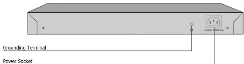
Rear Panel of TL-SG5428Figure 1-3
Grounding Terminal
The Switch already comes with lightning protection mechanism. You can also ground the Switch through the PE (Protecting Earth) cable of AC cord or with Ground Cable. For detailed information, please refer to Chapter 3 Lightning Protection.
Power Socket
Connect the female connector of the power cord here, and the male connector to the AC power outlet. Please make sure the voltage of the power supply meets the requirement of the input voltage (100-240V\~ 50/60Hz).

Caution: Please use the provided power cord.
InstallationChapter 2
Package Contents2.1
Make sure that the package contains the following items. If any of the listed items is damaged or missing, please contact your distributor.

Safety Precautions2.2
To avoid any device damage and bodily injury caused by improper use, please observe the following rules.
■ Safety Precautions
- Keep the power off during the installation.
- Wear an ESD-preventive wrist strap, and make sure that the wrist strap has a good skin contact and is well grounded.
- Use only the power cord provided with the Switch.
- Make sure that the supply voltage matches the specifications indicated on the rear panel of the Switch.
- Ensure the vent hole is well ventilated and unblocked.
- Do not open or remove the cover of the Switch.
- Before cleaning the device, cut off the power supply. Do not clean it by the waterish cloth, and never use any other liquid cleaning method.
■ Site Requirements
To ensure normal operation and long service life of the device, please install it in an environment that meets the requirements described in the following subsection.
Temperature/Humidity

Please keep a proper temperature and humidity in the equipment room. Too high/low humidity may lead to bad insulation, electricity leakage, mechanical property changes and corrosions. Too high temperature may accelerate aging of the insulation materials and can thus significantly shorten the service life of the device. For normal temperature and humidity of the device, please check the following table.
| Environment Temperature Humidity | ||
| Operating | 0°C ~ 40°C | 10% ~ 90%RH Non-condensing |
| Storage -40°C ~ 70°C 5% ~ 90%RH Non-condensing | ||
Clearness


The dust accumulated on the Switch can be absorbed by static electricity and result in poor contact of metal contact points. Some measures have been taken for the device to prevent static electricity, but too strong static electricity can cause deadly damage to the electronic elements on the internal circuit board. To avoid the effect of static electricity on the operation of the Switch, please attach much importance to the following items:
- Dust the device regularly, and keep the indoor air clean.
- Keep the device well grounded and ensure static electricity has been transferred.
Electromagnetic Interference


Electronic elements including capacitance and inductance on the device can be affected by external interferences, such as conducted emission by capacitance coupling, inductance coupling, and impedance coupling. To decrease the interferences, please make sure to take the following measures:
- Use the power supply that can effectively filter interference from the power grid.
- Keep the device far from high-frequency, strong-current devices, such as radio transmitting station.
- Use electromagnetic shielding when necessary.
Lightening Protection


Extremely high voltage currents can be produced instantly when lightning occurs and the air in the electric discharge path can be instantly heated up to 20,000°C. As this instant current is strong enough to damage electronic devices, more effective lightning
protection measures should be taken.
- Ensure the rack and device are well earthed.
- Make sure the power socket has a good contact with the ground.
- Keep a reasonable cabling system and avoid induced lightning.
- Use the signal SPD (Surge Protective Device) when wiring outdoor.

Note: For detailed lightning protection measures, please refer to Chapter 3 Lightning Protection.
Installation Site

When installing the device on a rack or a flat workbench, please note the following items:
- The rack or workbench is flat and stable, and sturdy enough to support the weight of 5.5kg at least.
- The rack or workbench has a good ventilation system. The equipment room is well ventilated.
- The rack is well grounded. Keep the power socket less than 1.5 meters away from the device.
Installation Tools2.3
- Phillips screwdriver
■ ESD-preventive wrist wrap
•

Note: These tools are not provided with our product. If needed, please self purchase them.
Product Installation2.4
■ Desktop Installation
To install the device on the desktop, please follow the steps below:
Set the device on a flat surface strong enough to support the entire weight of the 1. device with all fittings.
Remove the adhesive backing papers from the rubber feet.2.
Turnover the device and attach the supplied rubber feet to the recessed areas on 3. the bottom at each corner of the device.

Desktop InstallationFigure 2-1
■ Rack Installation
To install the device in an EIA standard-sized, 19-inch rack, follow the instructions described below:
Check the grounding and stability of the rack.1.
Secure the supplied rack-mounting brackets to each side of the device with supplied 2. screws, as illustrated in the following figure.

Bracket InstallationFigure 2-2
After the brackets are attached to the device, use suitable screws (not provided) to 3. secure the brackets to the rack, as illustrated in the following figure.

Rack Installation Figure 2-3

Caution:
- Please set 5\~10cm gaps around the device for air circulation.
- Please avoid any heavy thing placed on the device.
- Please mount devices in sequence from the bottom to top of the rack and ensure a certain clearance between devices for the purpose of heat dissipation.
Lightning ProtectionChapter 3
Cabling Reasonably3.1
In the actual network environment, you may need cable outdoors and indoors, and the requirements for cabling outdoors and indoors are different. A reasonable cabling system can decrease the damage of induced lightning to devices.

Note: It's not recommended using Ethernet cables outdoors. When cabling outdoors, please use a signal lightning arrester.
■ Requirements for Cabling Outdoors
- Aerial cabling without safeguard is not allowed.

flowchart
graph LR
    A["Building 1"] --> B["Black lightning bolt"]
    C["Building 2"] --> B
    style A fill:#f9f,stroke:#333
    style C fill:#f9f,stroke:#333
- It's not allowed cabling down the building to connect network devices in different floors.

- Outdoor cables should be buried and paved to the indoor through basement. A piece of steel wire should be paved underground along the pipe and connected to the lightning protection terminal of the building for shielding. Before connecting the cable to the device, install a signal lightning arrester on the corresponding port.
- When an aerial cable is set up, the cable should be through a metal pipe (15m long at least) before coming into the building. The two ends of this metal pipe should be grounded. Before connecting the cable to the device, install a signal lightning arrester on the corresponding port.
- It's not necessary to pave STP cables through pipes. The shielded layer of STP cable should be well grounded. Before connecting the cable to the device, install a signal lightning arrester on the corresponding port.
■ Requirements for Cabling Indoors
When cabling indoors, keep a certain distance away from the devices that may cause high-frequency interferences, such as down-conductor cable, powerline, power transformer and electromotor.
- The main cable should be paved in the metal raceway of the access shaft. When cabling, keep the loop area formed by the cable itself as small as possible.
- Requirements for the distance between Ethernet cable and other pipelines are shown in the table.
| Other Pipelines | Ethernet Cable | |
| Min Parallel Net Length L (mm) | Min Parallel-overlapping Net Height H (mm) | |
| Down-conductor 1000 300 | ||
| PE 50 20 | ||
| Service pipe 150 20 | ||
| Compressed air pipe 150 20 | ||
| Thermal pipe (not wrapped) | 500 500 | |
| Thermal pipe (wrapped) 300 | 300 | |
| Gas pipe 300 20 | ||
The two diagrams below demonstrate parallel net length and parallel-overlapping net height.
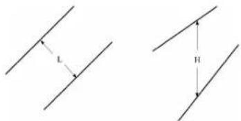

Note: The above minimum net length/height is required when metal raceway is not used. If any requirements cannot be met, you can add a steel tube or metal raceway for shielding.
- Requirements for the distance between Ethernet cable and high-power electric devices are in following tables.
| Cable | Pave Way | Min Parallel Length (mm) |
| <2kVA powerline | Parallel cabling | 130 |
| One is in the grounded metal raceway or metal pipe | 70 | |
| The both are in the grounded metal raceway or metal pipe | 10 | |
| 2~5kVA powerline | Parallel cabling | 300 |
| One is in the grounded metal raceway or metal pipe | 150 | |
| The both are in the grounded metal raceway or metal pipe | 80 | |
| >5kVA powerline | Parallel cabling | 600 |
| One is in the grounded metal raceway or metal pipe | 300 | |
| The both are in the grounded metal raceway or metal pipe | 150 |
| Device | Min Distance (m) |
| Switch case | 1.00 |
| Transformer room | 2.00 |
| Elevator tower | 2.00 |
| Air-conditioner room | 2.00 |
Connect to Ground3.2
Connecting the device to ground is to quickly release the lightning over-voltage and over-current of the device, which is also a necessary measure to protect the body from electric shock.
In different environments, the device may be grounded differently. The following will instruct you to connect the device to the ground in two ways, connecting to the grounding bar or connecting to the ground via the power cord. Please connect the device to ground in the optimum way according to your specific operation environment.
■ Connecting to the Grounding Bar
If the device is installed in the Equipment Room, where a grounding bar is available, you are recommended to connect the device to the Grounding Bar as shown in the following figure.

① Switch (Rear Panel)
② Grounding Terminal
③ Ground Cable
④ Grounding Bar
Connecting to the Grounding BarFigure 3-1

Note: The grounding bar is not provided with our product. If needed, please self-purchase it.
■ Connecting to the Ground via the Power Supply
If the device is installed in the normal environment, the device can be grounded via the PE (Protecting Earth) cable of the AC power supply as shown in the following figure.
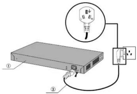
① Switch (Rear Panel)
② AC Power Cord (with PE cable)
Connecting to the GroundFigure 3-2

Note:
- The figure is to illustrate the application and principle. The power cord you get from the package and the socket in your situation will comply with the regulation in your country, so they may differ from the figure above.
- If you intend to connect the device to the ground via the PE (Protecting Earth) cable of AC power cord, please make sure the PE (Protecting Earth) cable in the electrical outlet is well grounded in advance.
Equipotential Bonding3.3
Equipotential Bonding is the practice of intentionally electrically connecting all earthed systems to the same grounding grid or connecting the grounding grids of all the earthed systems together through the ground or overground metal so as to create an earthed equipotential zone. When lightning occurs, the high voltage produced by lightning current in all systems will meanwhile exist in their ground cables, and thus all ground cables have the same electrical potential and basically eliminate the electric strikes between the systems.
The figure below illustrates how to practice equipotential bonding in a network.

① Grounding Terminal Equipotential Bonding Cable
③
④ Grounding Bar Ground Cable
Equipotential BondingFigure 3-3
When equipotential bonding, please note that the cable should be copper wrapped Kelly with its area being 6mm ^2 at least. The shorter cable the better, and use a grounding bar to establish an equipotential bonding point.

Note: The equipotential bonding cable is not provided with our product. If needed, please self purchase it.
Use Lightning Arrester3.4
Power lightning arrester and signal lightning arrester are used for lighting protection.
Power lightning arrester is used for limiting the voltage surge due to a lightning. If an outdoor AC power cord should be directly connected to the device, please use a power lightning arrester.

Note: Power lightning arrester is not provided with our product. If needed, please self purchase it.
Signal lightning arrester is used to protect RJ45 ports of the device from lightning. When cabling outdoors, please install a signal lightning arrester before connecting the cable to the device.
When purchasing or using a signal lightning arrester, please observe the following rules:
- The port rate of the signal lightning arrester should match the rate of the desired port on the device. If it is not matched, this signal lighting arrester will not work. Purchase a standard lightning arrester.
- Install signal lightning arrester near the protected device and connect it to the ground via a shorter ground cable.
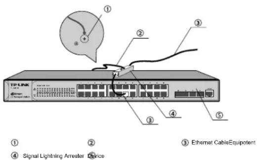
Lightning Arrester ConnectionFigure 3-4

Note:
- Signal lightning arrester is not provided with our product. If needed, please self purchase it.
- The SFP ports performe transmission by optical fiber which is immune to electric conduction. Therefore, 3.4 Use Lightning Arrester is not appropriate for SFP ports but only applies to RJ45 ports.
ConnectionChapter 4
Ethernet Port4.1
Connect the Ethernet ports of the Switch to the network devices by RJ45 cable as the following figure shown.
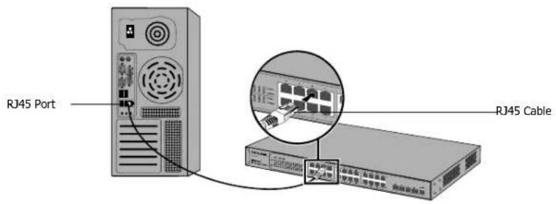
Connecting the RJ45 PortFigure 4-1
SFP Port4.2
Connect the SFP port to a SFP module. For the switch, if an SFP transceiver (purchased separately) is installed in a slot and has a valid link on the port, the associated RJ45 port will be disabled and cannot be used. Figure 4-2 demonstrates the connection of SFP port to a SFP module.

Inserting the SFP ModuleFigure 4-2

Note:
- A Combo port refers to two Ethernet interfaces in a device panel (normally one is an SFP slot and the other is an RJ45 port). Inside the device there is only one forwarding interface. Users can choose one to use depending on the actual network requirements, but not two simultaneously. When one port is working, the other is disabled.
- For a Combo port, the SFP slot takes priority over its associated RJ45 port. When the SFP slot and its associated RJ45 port are both connected, whatever the priority of connection, the SFP port will always work normally while the RJ45 port will be disabled.
Optical fiber
Optical fiber can be used as a medium for telecommunication and computer networking. It is especially advantageous for long-distance communications, because light propagates through the fiber with much less attenuation compared to electrical cables. For short distance applications, such as a network in an office building, optical fiber permits transmission over longer distances and at higher bandwidths (data rates) than other forms of communication. Fibers are used instead of metal wires because signals travel along them with less attenuation and are also immune to electromagnetic interference. There is no cross-talk between signals in different cables, and no pickup of environmental noise.
SFP Module
SFP module are input/output (I/O) devices that plug into a Gigabit Ethernet port, linking the port with a 1000BASE-X fiber-optic network. A SFP module possesses a receiver port (RX) and a transmitter port (TX) that make up one optical interface. To enjoy the required optical reach, users can freely select the appropriate SFP module over the available optical fiber type such as multi-mode fiber or single-mode fiber. Multi-mode fibers generally have a larger core diameter, and are used for short-distance communication links and for applications where high power must be transmitted. Single-mode fibers are used for most communication links longer than 1,050 meters that is 3,440 feet.
TL-SG5428 and TL-SG5412F are compatible with all kinds of gigabit SFP modules including sigle-mode and multi-mode. The transmission distance and the type of optical fiber are determined by the SFP module you choose. Here you are recommended to choose the SFP modules produced by TP-LINK, which can perfectly enlarge the bandwidth and extend your network.
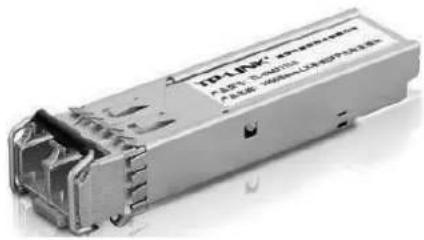
natural_image
Exterior view of a gray electronic device with internal components and mounting brackets (no visible text or symbols)SFP moduleFigure 4-3
The following table shows the detailed information of two SFP modules (TL-SM311LS and TL-SM311LM) produced by TP-LINK, which makes you have a round idea about it so as to give you a reference for choosing the suitable SFP module.
| Model | TL-SM311LS | TL-SM311LM |
| Standards | IEEE 802.3zCSMA/CDTCP/IP | IEEE 802.3zCSMA/CDTCP/IP |
| Transmission Media Single-mode fiber (9/125um) Multi-mode fiber (50/125um or 62.5/125um) | ||
| Transmission Speed 1.25Gbps 1.25Gbps | ||
| Transmission Distance 10km 550m | ||
| Output Center Wavelength 1310nm 850nm | ||

Note: For security, please wear an ESD-preventive wrist strap when installing or removing the SFP module. For detailed information, please refer to Chapter 3 Lightning Protection.
Console Port4.3
CLI (Command Line Interface) enables you to manage the Switch, thus you can load the CLI after connecting the PCs or Terminals to the console port on the Switch via the provided cable.
Connect the console port of the device with your computer by the console cable as the following figure shown.

Connecting the Console PortFigure 4-4
You can also manage the device through the console port, for details please refer to the CLI Reference Guide on the resource CD.

Note:
- The console port is the first port on the right of the front panel.
- Please keep the device power off when plugging the console cable.
- Do not connect the console port with other ports by RJ45 cable.
Verify Installation4.4
After completing the installation, please verify the following items:
- There are 5\~10cm of clearance around the sides of the device for ventilation and the air flow is adequate.
- The voltage of the power supply meets the requirement of the input voltage of the device.
- The power socket, device and rack are well grounded.
- The device is correctly connected to other network devices.
Power On 4.5
Plug the female connector of the provided power cord into the power socket of the device, and the male connector into a power outlet as the following figure shown.

natural_image
Illustration of a network switch with cable and socket (no text or symbols)Connecting to Power SupplyFigure 4-5

Note: The figure is to illustrate the application and principle. The power cord you get from the package and the socket in your situation will comply with the regulation in your country, so they may differ from the figure above.
Initialization4.6
After the device is powered on, it begins the Power-On Self-Test. A series of tests run automatically to ensure the device functions properly. During this time, its LED indicators will respond as follows:
- The PWR LED indicator will light on all the time.
- After keeping off for several seconds, the LED indicators of all the ports will flash momentarily and then turn off again after the initialization.
- The SYS LED indicator will flash, which represents a successful initialization.
ConfigurationChapter 5
Configure the Switch via GUI5.1
To access the GUI of the Switch, open a web browser and type the default 1. management address http://192.168.0.1 in the address field of the browser, then press the Enter key.

Web BrowserFigure 5-1

Note: To log on to the GUI of the Switch, the IP address of your PC should be set in the same subnet addresses of the Switch. The IP address is 192.168.0.x ("x" is any number from 2 to 254), Subnet Mask is 255.255.255.0.
For the detailed instructions as to how to do this, please refer to Appendix B in the User Guide on the Resource CD.
Enter admin for the default User Name and Password, both in lower case letters. 2. Then click the Login button or press the Enter key.

LoginFigure 5-2
After a successful login, the main page will appear as the following figure, and you 3. can configure the function by clicking the setup menu on the left side of the screen.
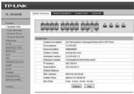
Main Page of the SwitchFigure 5-3
Configure the Switch Using CLI5.2
You can log on to the Switch and access the CLI by the following two methods:
- Log on to the Switch by the console port on the Switch.
- Log on to the Switch remotely by a Telnet or SSH connection through an Ethernet port.
■ Logon by a Console Port
To log on to the switch by the console port on the Switch, please take the following steps:
Connect the PCs or Terminals to the console port on the Switch by a provided cable.1. Click Start2.→All Programs→Accessories→Communications→Hyper Terminal to open the Hyper Terminal as the following figure shown.
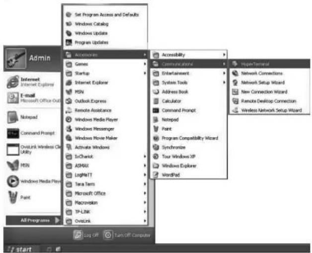
Open Hyper TerminalFigure 5-4
The Connection Description Window will prompt as Figure 5-5. Enter a name into the 3. Name field and click OK.

Connection DescriptionFigure 5-5
Select the port to connect in Figure 5-6, and click OK.4.

Select the port to connectFigure 5-6
Configure the port selected in the step above as the following Figure 5-7 shown. 5. Configure Bits per second as 38400, Data bits as 8, Parity as None, Stop bits as 1, Flow control as None, and then click OK.

Port SettingsFigure 5-7
Type the User name and Password in the Hyper Terminal window, the factory default 6. value for both of them is admin. The DOS prompt" TP-LINK>" will appear after pressing the Enter button as Figure 5-8 shown. It indicates that you can use the CLI now.

Log in the SwitchFigure 5-8
■ Logon by Telnet
To log on to the switch by a Telnet connection, please take the following steps:
Make sure the switch and the PC are in the same LAN.1.
Click Start2.>Run to open the Run window.

Open the Run windowFigure 5-9
Type cmd in the prompt Run window as Figure 5-10 and click OK.3.

Run WindowFigure 5-10
Type telnet 192.168.0.1 in the command prompt shown as Figure 5-11, and press the 4.Enter button.
![C:\WINDOWS\system37\cmd.exe Microsoft Windows XP [Version 5.1.2600] (C) Copyright 1985-2001 Microsoft Corp. G:\Documents and Settings\Admin>telnet 192:168.0.1_](/content/2026/05/1072394/images/ad05572e4d0e84ad2af6f3a3289bb970bac76e4ff91bf42f581d94c012b15540.jpg)
Connecting to the SwitchFigure 5-11
Type the User name and Password (the factory default value for both of them is 5. admin) and press the Enter button, then you can use the CLI now, which is shown as Figure 5-12.

Log in the SwitchFigure 5-12
For detailed CLI configuration instructions, please refer to the CLI Reference Guide on the resource CD.
TroubleshootingAppendix A
What could I do if I forgot the username and password of the Switch?Q1.
Connect the console port of the PC to the console port of the Switch and open hyper 1. terminal.
Power off and restart the Switch. When you are prompted that "Press CTRL-B to enter 2. the bootUtil" in the hyper terminal, please press CTRL-B key to enter into bootUtil menu shown as the following figure.

Enter the reset command to reset the system. The system will be reset to the factory 3. default settings, and the default login user name and password are both admin.
Why does the Power LED work abnormally?Q2.
The Power LED should be lit up when the power system works normally. If the Power LED worked abnormally, please take the following steps:
Make sure that the power cable is connected properly, and the power contact is normal.1.
Make sure the voltage of the power supply meets the requirement of the input voltage of 2. the Switch.
What could I do if I could not access the web-based configuration page?Q3.
You are recommended to check the following items:
Check every port LED on the Switch and make sure the cable is installed properly.1.
Try another port on the Switch and make sure the cable meets the requirement and 2. works normally.
-
Turn off the power. After a while, turn on the power again.
-
Make sure the IP address of your PC is set within the subnet of the Switch.
If you still cannot access the configuration page, please restore the Switch to its factory 5. defaults. Then the IP address should be set as 192.168.0.x ("x" is any number from 2 to 254) and Subnet Mask as 255.255.255.0.
Q4. Why does the hyper terminal display abnormally?
Please check as follows:
-
Make sure the power supply is normal and the console cable is properly connected.
-
Check if the console cable is the right type.
Ensure the parameters of the hyper terminal are correct: configure Bits per second as 3.38400, Data bits as 8, Parity as None, Stop bits as 1, and Flow control as None.
Hardware SpecificationsAppendix B
| Item Content | |
| Standards | IEEE 802.3 10Base-T |
| IEEE 802.3u 100Base-TX | |
| IEEE 802.3ab 1000Base-T | |
| IEEE 802.3z 1000Base-X | |
| IEEE 802.3x Flow Control | |
| Transmission Medium | 10Base-T: UTP/STP of Cat. 3 or above |
| 100Base-TX: UTP/STP of Cat. 5 or above | |
| 1000Base-T: 4-pair UTP (≤100m) of Cat. 5, Cat. 5e, and Cat. 6 or above | |
| 1000Base-X: MMF or SMF SFP Module (Optional) | |
| LEDs PWR, SYS, 1000Mbps, Link/Act, 10/100/1000Mbps BASE-T (for TL-SG5412F aly) | |
| Operating Temperature 0°C~40°C | |
| Storage Temperature -40°C~70°C | |
| Operating Humidity 10%~90%RH Non-condensing | |
| Storage Humidity 5%~90%RH Non-condensing | |
Technical SupportAppendix C
- For more help, please go to:
http://www.tp-link.com/en/support/faq
- To download the latest Firmware, Driver, Utility and User Guide, go to:
http://www.tp-link.com/en/support/download
- For all other technical support, please contact us by using the following details:
Global Tel: +86 755 26504400
E-mail: support@tp-link.com
Service time: 24hrs, 7 days a week
Singapore Tel: +65 62840493
E-mail: support.sg@tp-link.com
Service time: 24hrs, 7 days a week
UK Tel: +44 (0) 845 147 0017
E-mail: support.uk@tp-link.com
Service time: 24hrs, 7 days a week
USA/Canada Toll Free: +1 866 225 8139
E-mail: support.usa@tp-link.com
Service time: 24hrs, 7 days a week
Australia/New Zealand Tel: AU 1300 87 5465 NZ 0800 87 5465
E-mail: support@tp-link.com.au
support.nz@tp-link.com (New Zealand)
Service time: 24hrs, 7 days a week
Malaysia Tel: 1300 88 875465 (1300 88TPLINK)
Email: support.my@tp-link.com
Service time: 24hrs, 7 days a week
Turkey Tel: 444 19 25 (Turkish Service)
E-mail: support.tr@tp-link.com
Service time: 9:00 AM to 9:00 PM, 7 days a week
Italy Tel: +39 0230519020
E-mail: support.it@tp-link.com
Service time: Monday to Friday
9:00 AM to 1:00 PM, 2:00 PM to 6:00 PM
Indonesia Tel: (+62) 021 6259 135
E-mail: support.id@tp-link.com
Service time: Monday to Friday
9:00 -12:00; 13:00 -18:00
*Except public holidays
France Tel: +33 (0) 820 800 860 (French service)
Email: support.fr@tp-link.com
Fee: 0.118 EUR/min from France
Service time: Monday to Friday 9:00 AM to 6:00 PM
(Except French Bank holidays)
| Germany/Austria | Tel: +49 1805 875465 (German Service) / +49 1805 TPLINKE-mail: support.de@tp-link.comFee: 0.14 EUR/min from the German fixed phone network and up to 0.42 EUR/min from mobile phoneService time: Monday to Friday 9:00 AM to 6:00 PM GMT+ 1 or GMT+ 2 (Daylight Saving Time in Germany)*Except bank holidays in Hesse |
| Switzerland Tel: +41 (0) 848 800998 (German Service)E-mail: support.ch@tp-link.comFee: 4-8 Rp/min, depending on rate of different timeService time: Monday to Friday 9:00 AM to 6:00 PM, GMT+ 1 or GMT+ 2 (Daylight Saving Time) | |
| Ukraine Tel: 0-800-505-508E-mail: support.ua@tp-link.comService time: Monday to Friday 14:00 PM to 22:00 PM | |
| Russian Federation Tel: 8 (499) 754-55-608 (800) 250-55-60 (toll-free call from any RF region)E-mail: support.ru@tp-link.comService time: From 10:00 to 18:00 (Moscow time)*Except weekends and holidays in Russian Federation | |
| Brazil Toll Free: 0800-770-4337(Portuguese Service)E-mail: suporte.br@tp-link.comService time: Monday to Saturday 08:00 AM to 08:00 PM | |
| Poland Tel: +48 (0) 801 080 618 / +48 22 7217563(if calls from mobile phone)E-mail: support.pl@tp-link.comService time: Monday to Friday 9:00 AM to 5:00 PM.GMT+1 or GMT+2 (Daylight Saving Time) | |
-1
-
1_
1


- FCC STATEMENT
- FC
- CE Mark Warning
- CE
- Related Document
- About this Installation Guide
- Audience
- Conventions
- Contents
- Chapter 1 Introduction \_\_\_\_ 01
- Chapter 2 Installation ———— 04
- Chapter 3 Lightning Protection \_\_\_\_ 08
- Chapter 4 Connection 13
- Chapter 5 Configuration ———— 17
- Appendix A Troubleshooting — 22
- Appendix B Hardware Specifications — 23
- Appendix C Technical Support — 24
- IntroductionChapter 1
- Product Overview1.1
- Appearance1.2
- ■ Front Panel
- Note:
- 10/100/1000Mbps RJ45 Port
- SFP Port
- Console Port
- ■ Rear Panel
- Grounding Terminal
- Power Socket
- InstallationChapter 2
- Package Contents2.1
- Safety Precautions2.2
- ■ Safety Precautions
- ■ Site Requirements
- Clearness
- Electromagnetic Interference
- Lightening Protection
- Installation Tools2.3
- Product Installation2.4
- ■ Desktop Installation
- ■ Rack Installation
- Caution:
- Lightning ProtectionChapter 3
- Cabling Reasonably3.1
- ■ Requirements for Cabling Outdoors
- ■ Requirements for Cabling Indoors
- Connect to Ground3.2
- ■ Connecting to the Grounding Bar
- ■ Connecting to the Ground via the Power Supply
- Equipotential Bonding3.3
- Use Lightning Arrester3.4
- ConnectionChapter 4
- Ethernet Port4.1
- SFP Port4.2
- Optical fiber
- SFP Module
- Console Port4.3
- Verify Installation4.4
- Power On 4.5
- Initialization4.6
- ConfigurationChapter 5
- Configure the Switch via GUI5.1
- Configure the Switch Using CLI5.2
- ■ Logon by a Console Port
- ■ Logon by Telnet
- TroubleshootingAppendix A
- Technical SupportAppendix C
Brand : TP-LINK
Model : JetStream L2 Managed TL-SG5428
Category : Network switch