Soundweb 9008 - Processor BSS Audio - Free user manual and instructions
Find the device manual for free Soundweb 9008 BSS Audio in PDF.


| Product Type | Digital Audio Processor |
| Brand | BSS Audio |
| Model | Soundweb 9008 |
| Channels | 8 Input / 8 Output |
| Form Factor | 19-inch Rackmount, 1U |
| Dimensions (W x H x D) | 483 mm x 44 mm x 200 mm (19.0" x 1.7" x 7.9") |
| Weight | Approximately 4.0 kg (8.8 lbs) |
| Power Supply | 100-240 V AC, 50/60 Hz, 30 W max |
| Audio Sampling Rate | 48 kHz or 96 kHz (configurable) |
| Bit Depth | 24-bit |
| Signal Processing | Mixing, Equalization, Dynamics, Delay, Matrix Routing |
| Control Interface | RS-232, Ethernet (TCP/IP), GPIO |
| Audio Connectors | Balanced XLR (each channel), Euroblock for GPIO |
| Supported Audio Formats | AES/EBU, Analog, CobraNet (optional) |
| Preset Storage | 256 presets (user definable) |
| Latency | Less than 1 ms at 48 kHz |
| Operating Temperature | 0°C to 40°C (32°F to 104°F) |
| Humidity Range | 10% to 90% non-condensing |
| Maintenance | Clean with dry cloth; avoid liquids. Check ventilation quarterly. |
| Safety Precautions | Use grounded outlet; do not expose to rain or moisture. Disconnect power before servicing. |
| Spare Parts | Contact BSS Audio authorized service center for replacement parts. |
| Repairability | Service by qualified personnel only. Refer to service manual. |
Frequently Asked Questions - Soundweb 9008 BSS Audio
User questions about Soundweb 9008 BSS Audio
0 question about this device. Answer the ones you know or ask your own.
Ask a new question about this device
Download the instructions for your Processor in PDF format for free! Find your manual Soundweb 9008 - BSS Audio and take your electronic device back in hand. On this page are published all the documents necessary for the use of your device. Soundweb 9008 by BSS Audio.
USER MANUAL Soundweb 9008 BSS Audio
9008 Networked Signal Processor Installation Guide

Regulatory Information
An example of this equipment has been tested and found to comply with the following European and international Standards for Electromagnetic Compatibility and Electrical Safety:
Emissions (EU): EN55013 (1990)
Generic Immunity (EU): EN50082-1 (1997)
Electrical Safety (EU): EN60065+A11 (1993)
Electrical Safety (USA): UL6500/ETL (1996)
Electrical Safety (CAN): CAN/CSA-E65/ETLc (1994)
Radiated Emissions (USA): FCC parts 15 Class B

119379


119379
For continued compliance with international EMC regulations, it is important that all cables be screened, and connected as follows:
• Audio cable screens to their 9008 connector ground.
- Control cable screens to the ground screws adjacent to the connector.
Network cables should be of type CAT. 5
IMPORTANT SAFETY INFORMATION
Do not remove covers.
No user serviceable parts inside - refer servicing to qualified service personnel. This equipment must be earthed.
It should not be necessary to remove any protective earth or signal cable shield connections to prevent ground loops. Any such disconnections are outside the recommended practice of BSS Audio and will render the EMC or safety certification void.
Mechanical Installation
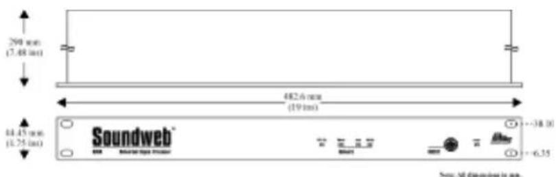
If the unit is likely to undergo extreme vibration through extensive road trucking and touring, it must be supported at the rear and/or sides to lessen the stress on the front mounting flange. Use either a ready-built rack tray or mount the 9008 unit between other units. Damage caused by insufficient support is not covered by the warranty.
To prevent cosmetic damage to the front panel finish, use protective plastic cups under the rack mounting bolts.
Front Panel LED Functions
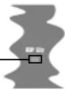
DSP Clip
Illuminated = indicates that the processed signal is clipping internally.
Network
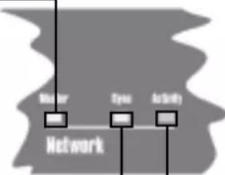
Master
Flashing = the network is initialising. If the led continues to flash for more than a few seconds, there is a cabling fault - either a double ring error or a problem with one of the cable connectors.
Steady = this unit has become the clockmaster for the network.
Off = this unit is clienting to an external master clock.
flowchart
graph TD
    A["Master"] --> B["Eye"]
    B --> C["Activity"]
    style A fill:#fff,stroke:#000
    style B fill:#fff,stroke:#000
    style C fill:#fff,stroke:#000
Sync
Steady = indicates the presence of one or more valid network connections.
Flashing = there is a problem with the incoming network signal - check connections and/or possibly the maximum cable length has been exceeded.
Activity
Flashing Yellow = indicates data transfer. The flashing is not regular, but dependent on the rate of transfer.
Flashing Red = indicates bad data and is usually caused by network faults. Check network connections, see Rear Panel details.
Power
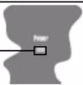
Illuminated = indicates that the power supply is functioning.
9008 Installation Guide
Rear Panel Details
Mains inlet
IEC power connector, for connection to mains supply (100-270V AC, 50/60Hz).
Mains fuse holder
Requires a 20mm T1A type fuse. Do not replace with anything other than the recommended fuse.
Audio & Control connectors
9008 audio and control connections are via Klippon (also known as BL, Phoenix or Combicon) pluggable terminal block connectors.
8 x 6-way female Klippon connectors are supplied for making these connections.
For audio and network cables and looms, see the Product Overview 2000 catalogue from:
Direct Cable Systems Ltd.
Tel: (020) 7485 0899
www.directcable.co.uk
Neutricon-Neutricon tour grade network cable. P/N 150001
Phoenix-XLR audio cable P/N 100521
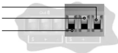
Audio Output wiring convention
Soundweb products provide cable shielding 'back from the destination' to eliminate ground loop problems. Therefore, the shield (S) connection on an input is grounded, whereas the shield connection on an output is floating (although connected via an internal network to ground for EMC compliance).
Balanced wiring - The convention for balanced wiring (2-core plus shield) is:
Balanced connection 9008 connection
Pin 3: Cold '-'
Pin 2: Hot '+'
Pin 1 : Shield
Network In/Out
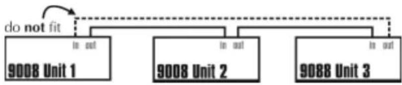
The Network Out socket on a Soundweb unit connects to the Network In socket on another unit. Repeat this process to make a network of devices. Audio channels are passed 'downstream' from the Net Out socket on the first unit to the Net In socket on the next unit. The Soundweb system automatically completes this 'daisy chain' of device connections to form a loop (using a 'back channel'), as shown by the dotted line in the diagram below.
flowchart
graph TD
    A["9008 Unit 1"] --> B["do not fit"]
    C["9008 Unit 2"] --> D["in out"]
    E["9088 Unit 3"] --> F["in out"]
This shows that audio channels are routed back from the terminal device (the one without a connection to its Net Out socket) to the first device (the one without a connection on its Net In socket).
There must be no physical cable connection between the two end devices.
The connecting cable is CAT. 5 network cable terminated with RJ45 connectors, with all 8 cores wired straight through.
Note that the twisted pairs in any CAT. 5 network cable must be wired to the following pin pairs at each terminal:
1 (White/Orange) with 2 (Orange)
3 (White/Green) with 6 (Green)
4 (Blue) with 5 (White/Blue)
7 (White/Brown) with 8 (Brown)
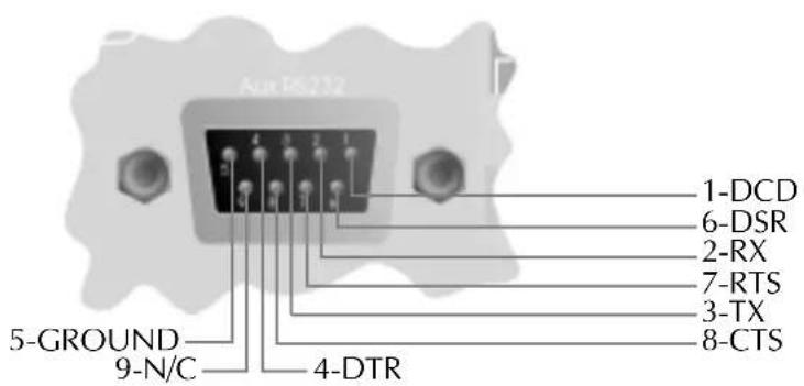
Aux. RS232
An alternative connection for a control PC, modem or AMX/Crestron type panel. This port works at 115200bps. Note that AMX panels only currently connect at 38400bps.
9008 Installation Guide
CONTROL INPUTS
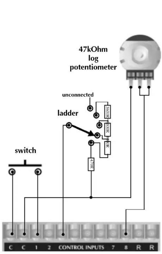
Used to connect switches or potentiometers, e.g. 9012 selector wallplate (Part no. Z-SW9012).
Looking at the control port connector (on the back of the unit), there are two common (ground) connections C to the left of the eight CONTROL INPUTS and, two software assignable reference voltage outputs R to the right.
The control ports now have two modes of operation. In Soundweb Designer's Control Ports window these are labelled '2-wire' and '3-wire'.
2-wire mode
In this mode the eight CONTROL INPUTS are internally 'pulled up' to +5V DC via a 4.7kOhm resistor. Therefore, no external voltage source is needed to create contact closure to ground for switches such as mute buttons or, resistance to ground (for other multi-state or continuous controls such as Parameter Presets or faders).
See the Soundweb Designer help for a table of resistor values for use with Parameter Presets or source selectors.
Two 'common' ground connections are provided using the two C connectors to the left of the CONTROL INPUTS.
A 47kOhm-log potentiometer (Part no. DM10018) connected between a control input and common will allow parameters to be controlled linearly.
3-wire mode
This mode allows the use of linear pots or faders for continuous controls. A pot would be wired as a potential divider with the top of the track connected to the reference output R, the wiper to a control input and the bottom of the track to a common C. For good performance pots with track resistance between 10K and 100K Ohms are recommended.
LOGIC OUTPUTS
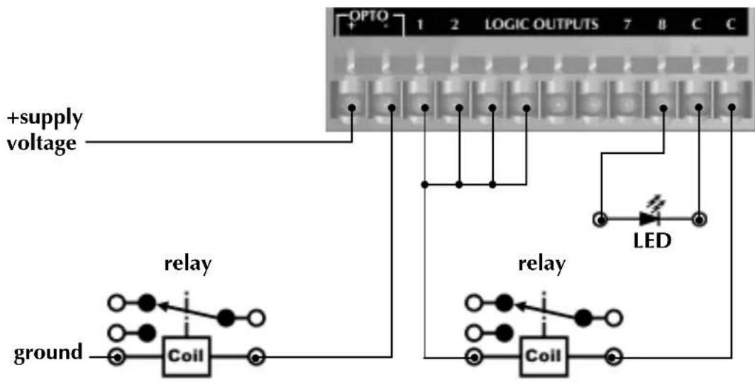
Used to connect 'tally' indicator LED's or relays.
There are eight standard LOGIC OUTPUTS which produce 0V or +5V DC via an internal 440 Ohm resistor and two internally connected common (ground) connections C.
An LED connected between one output (Anode, A) and common (Cathode, K) will illuminate when the logic output is activated, without requiring any external current limiting resistor.
A high sensitivity relay (such as a reed relay) may be driven by connecting four outputs in parallel. This arrangement will develop 4V across a 500-Ohm coil, providing that all four outputs are made logic 1 simultaneously.
OPTO Output
In addition to the eight standard logic outputs, there is an isolated output, which fails safe (open circuit) if the unit becomes faulty.
This is effectively the collector-emitter of a transistor (which may be thought of as a switch), in series with a 220-Ohm protection resistor. In conjunction with an external DC power source (max 80V), this may be used to drive various loads such as relays.
Control Inputs and Logic Outputs connection diagram
2 wire mode
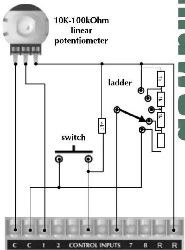
3 wire mode
flowchart
graph TD
    A["OPTO"] --> B["1"]
    A --> C["2"]
    A --> D["LOGIC OUTPUTS"]
    A --> E["7"]
    A --> F["8"]
    A --> G["C"]
    A --> H["C"]
    I["ground"] --> J["Coil"]
    K["relay"] --> L["Coil"]
    M["+supply voltage"] --> N["Relay"]
    O["LED"] --> P["Relay"]
    Q["Ground"] --> R["Coil"]
General
DSP capability 200MIPS (Million Instructions Per Second)
Frequency response 15Hz to 20KHz (+-0.5dB)
Total Harmonic Distortion (THD) <0.01% (20Hz to 20KHz, +10dBu output)
Dynamic range 105dB typical (22Hz to 22KHz unweighted)
108dB typical (A-weighted)
Maximum output level +20dBu
Inter-channel crosstalk <-75dB
Maximum network cable length 300m/1000ft
Mains supply 85-270V AC, 50/60Hz
Power consumption <35VA
Control Ports
Control input voltage 0 to 4.5v
Control input impedance (2 wire mode) 4.7kOhms to +5V
Control input impedance (3 wire mode) >1MOhm
Logic output voltage 0 or +5V unloaded
Logic output impedance 440 Ohm
Opto output current 14mA max
Opto output withstanding voltage 80V max
Opto output series impedance 220 Ohms (isolated)

- Networked Signal Processor Installation Guide
- Regulatory Information
- IMPORTANT SAFETY INFORMATION
- Mechanical Installation
- Front Panel LED Functions
- DSP Clip
- Network
- Master
- Sync
- Activity
- Power
- Rear Panel Details
- Mains inlet
- Mains fuse holder
- Audio & Control connectors
- Audio Output wiring convention
- Balanced connection 9008 connection
- Network In/Out
- Aux. RS232
- Installation Guide
- CONTROL INPUTS
- 2-wire mode
- 3-wire mode
- LOGIC OUTPUTS
- OPTO Output
- Control Inputs and Logic Outputs connection diagram
- General
- Control Ports
Brand : BSS Audio
Model : Soundweb 9008
Category : Processor