
MG2032 - Chopper Hobart - Free user manual and instructions
Find the device manual for free MG2032 Hobart in PDF.


| Product Type | Electric Meat Grinder (Mincer) |
| Brand | Hobart |
| Model | MG2032 |
| Motor Power | 1 HP (745 W) |
| Voltage | 208-230V / 60 Hz / 1-phase |
| Amperage | 7.5 A |
| Grinding Head Size | #32 (3.2 inch) |
| Included Plates | 3/16" and 3/8" (coarse and fine) |
| Feed Tray | Removable stainless steel |
| Construction | Stainless steel and aluminum |
| Dimensions (W x D x H) | 22" x 18" x 14" (559 x 457 x 356 mm) |
| Weight | 95 lbs (43 kg) |
| Production Rate | Up to 800 lbs/hr (363 kg/hr) |
| Safety Features | Automatic shutoff when lid open, thermal overload protection |
| Cleaning | Removable food contact parts, NSF approved |
| Warranty | 1 year parts and labor |
| Certifications | NSF, UL, CSA |
| Accessories (optional) | Stuffing tubes, extra plates, knife |
Frequently Asked Questions - MG2032 Hobart
User questions about MG2032 Hobart
0 question about this device. Answer the ones you know or ask your own.
Ask a new question about this device
Download the instructions for your Chopper in PDF format for free! Find your manual MG2032 - Hobart and take your electronic device back in hand. On this page are published all the documents necessary for the use of your device. MG2032 by Hobart.
USER MANUAL MG2032 Hobart
Previous models covered by this manual:
MG1532 ML-104878 7.5 HP Grind Motor + 1 HP Mix Motor
MG1532 ML-104883 5 HP Grind Motor + 1 HP Mix Motor
MG1532 ML-104879 7.5 HP Grind Motor + 1 HP Mix Motor w/ Side Feed
MG2032 ML-104884 7.5 HP Grind Motor + 1 HP Mix Motor
MG2032 ML-104885 7.5 HP Grind Motor + 1 HP Mix Motor w/ Side Feed

701 S. RIDGE AVENUE
TROY. OHIO 45374-0001
937 332-3000
www.hobartcorp.com
FORM 34389 Rev. B (Aug. 2001)

natural_image
Exterior view of a stainless steel HOBART industrial machine with control panel and wheels (no visible text or symbols on the device itself)
natural_image
Exterior view of a stainless steel HOBART industrial machine with wheels and control panel (no visible text or symbols on the device itself)MODEL MG1532 MIXER-GRINDER MODEL MG2032 MIXER-GRINDER
Installation, Operation, and Care of MG1532 & MG2032 MIXER-GRINDERS
SAVE THESE INSTRUCTIONS
GENERAL
The MG1532 & MG2032 Mixer-Grinders are designed to use a #32(42/46) size knife and plate (knives and plates are available at extra cost but not included with grinder). Do not use a plate with hole size smaller than ^3/32 ".
The MG1532 Mixer-Grinder is equipped with either a 5 or 7^1/2 HP Grind Motor and a 1 HP Mix Motor. The MG2032 Mixer-Grinder is equipped with a 7^1/2 HP Grind Motor and a 1 HP Mix Motor. On all models, the worm rotates at 216 RPM and the mix arm rotates at 23 RPM. The MG1532 with 5 HP Grind Motor is for fresh meat only, not for frozen product.
The inclined hopper permits lower, easier loading while the tilted worm provides a convenient output height.
Releasing the latch handle allows the hopper guard (lid) to open easily — torsion springs counterbalance the lid's weight.
The exclusive Hobart designed #46 Wedge cylinder grinding end speeds product from hopper to grinding end by pulling pieces of meat through the large upper opening of the cylinder (Fig. 1).
The MG1532 & MG2032 Mixer-Grinders may be ordered with any of the following options and/or accessories:
1) Caster sets and / or adjustable leg sets. The MG1532 & MG2032 Mixer-Grinders are equipped with flexible power supply cord and plug. Either a receptacle or a pendant type connector is available. The receptacle requires a type FD electrical box (not supplied).
2) Pneumatic foot switch accessory (can be easily added at any time).

natural_image
Metal mechanical component with a central hole and flanges (no text or symbols visible)Fig. 1
3) The hopper side-feed inlet can be ordered (and factory installed) for the right side of the hopper to allow product from a companion first cut grinder to feed directly into the hopper. A plug assembly for the side feed inlet, a drip cup, and adapter ring for the first-cut grinder are available accessories.
The MG1532 hopper can hold up to 150 pounds of fresh meat. The MG2032 hopper can hold up to 200 pounds of fresh meat. The MG1532 & MG2032 Mixer-Grinders can grind at a rate of 55 to 60 pounds of fresh boneless beef per minute, first or second cut through a 18 " plate. Pork can be ground first cut through a 34 " breaker plate and second cut through a 316 " plate at 60 to 65 pounds per minute. Up to 60 pounds of frozen meat per batch (on units with 712 HP Grind Motor only) can be ground from flake or stick form when tempered to 26^ or higher and first grind is through a 38 " or larger plate.
INSTALLATION
Immediately after unpacking the mixer-grinder, check for possible shipping damage. If the machine is found to be damaged, save the packaging material and contact the carrier within 15 days of delivery.
Prior to installation, test the electrical service to make sure it agrees with the specifications on the machine data plate (Fig. 5).
CASTER SETS AND / OR ADJUSTABLE LEG SETS
With the mixer-grinder securely elevated using the base frame for support, bolt the caster assemblies through the corner holes using four hex-head ^5/_16 -18 bolts, lockwashers, washers, and nuts for each caster, provided.
- When equipped with two Fixed and two Swivel casters, install Fixed Casters-without-Brake on rear corners of the machine and Swivel Casters-with-Brake on front corners.
- On machines with four identical legs or casters, install one on each corner.
All casters and leg sets use washers under the flange and above the machine base frame. Insert bolt up through the flange from the bottom with the lockwasher next to the nut on top (Fig. 2).

Fig. 2
LEVELING
Level the mixer-grinder, both front-to-back and side-to-side, by loosening the two set screws on the caster shaft (Fig. 2) and screwing the caster up or down. Tighten both set screws when level.
LUBRICATION
The mixer-grinder is shipped with oil already installed. If oil loss is observed, the oil levels of both transmissions should be checked prior to operation. Contact Hobart Service.
PNEUMATIC FOOT SWITCH
To install the pneumatic foot switch, remove the lower front panel (6 screws). Remove the knockout from the bottom front floor panel inside the machine compartment (Fig. 3) and insert the tube from the foot switch through the knockout hole. Remove the cap from the barbed fitting at the bottom left side of the control box (Fig. 3) and connect the tube from the pneumatic foot switch onto the barbed fitting using the clamp provided. A pliers will be needed to squeeze the clamp open during installation. Avoid kinking the tube.

Fig. 3
ELECTRICAL CONNECTION
WARNING: ELECTRICAL AND GROUNDING CONNECTIONS MUST COMPLY WITH APPLICABLE PORTIONS OF THE NATIONAL ELECTRICAL CODE AND/OR OTHER LOCAL ELECTRICAL CODES.
WARNING: DISCONNECT THE ELECTRICAL POWER SUPPLY AND PLACE A TAG AT THE DISCONNECT SWITCH INDICATING THAT YOU ARE WORKING ON THE CIRCUIT.
The mixer grinder is provided with a cord and plug and only requires that it be connected to an appropriately sized, grounding-type receptacle. Refer to the machine data plate (Fig. 5) and Electrical Data, below.
ATADLACIRTCELE
| Model | Horsepower | Volts / Hertz / Phase | Minimum Circuit Ampacity Maximum Protective Device MR | Receptacle | Plug |
| 2365 HP Grind23G iMP | 8003built before October, 2000 | 30 |  R03-1 R03-1 | B01.2pB | |
| 8003built after October, 2000PH1& 0923 | 30 |  R03-5 R03-5 | B06.1pB | ||
| 480 / 60 / 3 | 20 |  R02-6 R02-6 | P26.1pB | ||
| 23G 5pBiMP | 208 - 240 / 60 / 1MPH1& | 30 |  R03-6 R03-6 | B06L: pB |
Compiled in accordance with the National Electrical Code, NFPA-70, latest edition.
CHECK MOTOR ROTATION (Three-Phase Machines Only)
With the grinder cylinder in place and the hopper lid closed, check the rotation before making a permanent electrical connection by first pushing the MIX-GRIND START switch and then pushing the STOP switch (Fig. 4). The mixing arm and worm should both rotate counterclockwise, when viewed from the machine's front.
If the mixing arm and worm rotate clockwise, correct the rotation using the following procedure:
DISCONNECT THE ELECTRICAL POWER SUPPLY and interchange any two of the incoming power supply leads. Reconnect the power supply and push the MIX-GRIND START switch to verify that both the worm and the mixer arm rotate counterclockwise as viewed from the front of the machine.
CONTROL BOX HEATERS
The Mixer-Grinder has a heater in the control box and another heater in the front control panel to keep the controls dry. They are automatically ON when the machine is electrically connected. The Mixer-Grinder should always be connected EXCEPT when performing assembly, disassembly, cleaning, or maintenance of the machine. After cleaning, reconnect the electrical power supply.
OPERATION
CONTROLS (Fig. 4)

Fig. 4
MIX START Button—Starts rotating the mix arm. Use the Stop Button to stop mixing.
STOP Button — Turns the mixer-grinder off. Turns the Foot Switch off if it was on.
MIX/GRIND START Button — Starts rotating both mix arm and worm. Use the Stop Button to stop mixing and grinding.
FOOT SWITCH — When On, the Mix Start and Mix/Grind Start Buttons are inoperable and the accessory Foot Switch can be used to Mix/Grind ONLY. The indicator light shows when the Foot Switch is On. Push the STOP Button to turn the Foot Switch Off.
HOPPER LID INTERLOCK — An interlock switch requires the hopper lid to be closed before the machine can operate. Raising the hopper lid opens the electrical circuit and makes the machine inoperative.
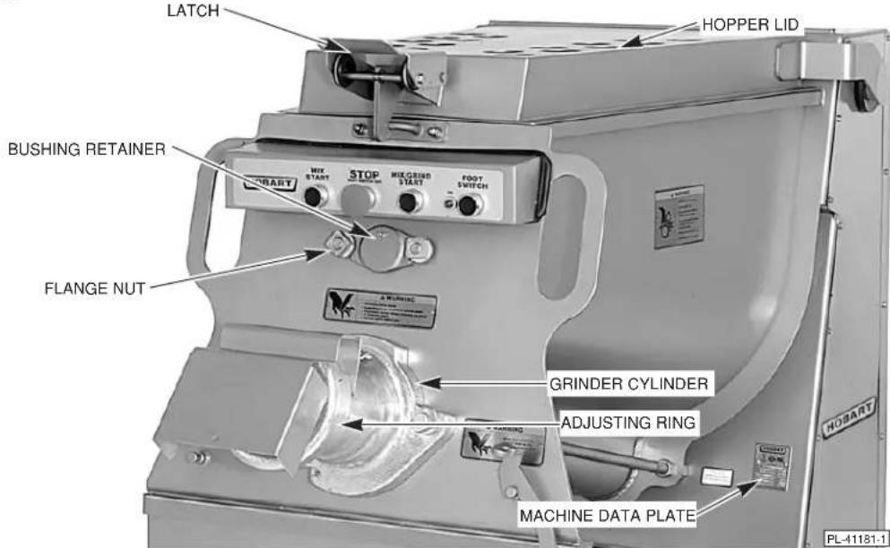
Fig. 5
GRINDER ATTACHMENT
The Wedge cylinder is marked TOP and BOTTOM. Before operating, make sure TOP is visible.
The grinder attachment can easily be removed for cleaning (see Cleaning, page 8). Use the spanner wrench to loosen the adjusting ring and remove the adjusting ring, plate and knife. Next loosen, but do not remove the grinder attachment's two flange nuts, using the spanner wrench. Rotate the cylinder clockwise and remove the cylinder; then, remove the worm. At reassembly, install the worm and then the cylinder. Make sure TOP is visible on the cylinder and that the cylinder's flange nuts are tight before assembling the knife, plate, and adjusting ring. Use only the flange nuts provided. Two studs on the front of the machine allow storage of the spanner wrench and pneumatic foot switch.
The rubber seal at the drive end of the worm can be removed by hand for cleaning. Grasp the outer flange of the seal or use a dull screwdriver to pry the seal loose. Reinstall seal before installing worm.
Before using the grinder attachment, take it apart and thoroughly wash it. The knife and plate need some preliminary lubrication: Rub tallow or food grade mineral oil over the cutting faces of these parts. When assembling the knife, be sure to turn the cutting side towards the perforated plate. The notch on the circumference of the plate must fit over the pin in the cylinder. Knives and plates must be sharp and true for proper cutting action. Keep the grinder attachment in a clean and sanitary condition.

Fig. 6
MIXING ARM
Loosen the bushing retainer's two flange nuts and remove the bushing retainer (Fig. 5). Raise the hopper lid and pull the mixing arm from the square drive end, lifting the mixing arm from the hopper (Fig. 6). When reassembling, make sure TOP on the bushing retainer is "up" so the mixing arm runs straight between the round bushing and the square drive-end. Remove the mixing arm after disassembly of the grinder cylinder and worm. Reassemble the mixing arm before assembly of the grinder cylinder and worm.
MIXING AND GRINDING
The MG1532 has a hopper capacity of up to 150 pounds of fresh meat depending on the type of product. The MG2032 has a hopper capacity of up to 200 pounds of fresh meat depending on the type of product. Don't put frozen product in units with 5 HP Grind Motor.
Second cut meat may be mixed in the hopper for any desired length of time. During the MIX operation, the mixing arm rotates and the grinder worm does not. Continuous self-feeding occurs along with grinding in the MIX-GRIND operation. Mixing of uncut or unground meat is not recommended.
Grinding Procedure
First Grind . . .
Fill hopper and close and latch the hopper lid. Overfilling will bend the hopper lid and may cause the interlock to open the electrical circuit.
Push MIX-GRIND Button to start grinding. Press STOP Button to stop grinding.
Second Grind . . .
Fill hopper and close and latch the hopper lid. Press MIX Button. After desired mixing, press the STOP Button. Then, press the MIX-GRIND Button to start grinding; press the STOP Button to stop grinding; or activate and use the optional accessory Foot Switch.
CLEANING
WARNING: DISCONNECT THE ELECTRICAL POWER SUPPLY BEFORE CLEANING OR SERVICING THIS MACHINE.
In any cleaning operation after disconnecting the electrical power supply, seal the receptacle to prevent entrance of moisture. To make this seal on Hobart supplied receptacles and pendant connectors, place the cover cap into position and turn the screw type sealing ring clockwise.
Remove the following components when cleaning: Mixing arm, grinder adjusting ring, knife and plate. Remove the cylinder before removing the worm. (Also remove the side feed hopper plug, when used.) The method for removing these components has already been described (refer to Grinder Attachment, page 7). The mixing arm seal and the worm seal (Fig. 6) should be removed by hand for cleaning. Grasp the outer flange or use a dull screwdriver to pry the seal loose.
The machine can be washed down with hot water or steam as is customary in meat processing operations. When using detergents and sanitizers, follow manufacturer's instructions. Rinse with clear water. Allow to air dry.
After cleaning the machine, apply food grade mineral oil to lubricate the inside rim of the mixing arm seals and the worm seal where the mixing arm and worm will touch the seals. Reassemble the mixing arm seal, worm seal, mixing arm, and bushing retainer. To reassemble mix arm and worm seals . . . Align tab at bottom of each seal with notch at bottom of applicable seal hole in end wall of hopper. Arrow at top of seal points up. Squeeze sides of seal and push in. Push in top of seal. Make sure seals are properly seated.
After cleaning, a light coat of food grade mineral oil is recommended for the cylinder, adjusting ring, knife, plate, and worm — before reassembly.
MAINTENANCE
WARNING: DISCONNECT THE ELECTRICAL POWER SUPPLY BEFORE CLEANING OR SERVICING THIS MACHINE.
LUBRICATION
Both motor bearings are pre-lubricated and sealed. No further lubrication is required.
Gear Case for Mixing Arm
Annually, or when needed, contact Hobart Service for lubrication maintenance.
Gear Case for Worm
Annually, or when needed, contact Hobart Service for lubrication maintenance.
SERVICE
Contact your local Hobart Service Office for any repairs or adjustments needed on this equipment.


- Installation, Operation, and Care of MG1532 & MG2032 MIXER-GRINDERS
- SAVE THESE INSTRUCTIONS
- GENERAL
- INSTALLATION
- CASTER SETS AND / OR ADJUSTABLE LEG SETS
- LEVELING
- LUBRICATION
- PNEUMATIC FOOT SWITCH
- ELECTRICAL CONNECTION
- CHECK MOTOR ROTATION (Three-Phase Machines Only)
- CONTROL BOX HEATERS
- OPERATION
- GRINDER ATTACHMENT
- MIXING ARM
- MIXING AND GRINDING
- Grinding Procedure
- CLEANING
- MAINTENANCE
- Gear Case for Mixing Arm
- Gear Case for Worm
- SERVICE
Brand : Hobart
Model : MG2032
Category : Chopper