
4146 - Chopper Hobart - Free user manual and instructions
Find the device manual for free 4146 Hobart in PDF.


| Product Type | Chopper / Mincer (Floor Model) |
| Brand | Hobart |
| Model | 4146 |
| Motor Power | 5 HP |
| Worm Speed | 215 RPM |
| Knife and Plate Size | #32 |
| Feed Pan Dimensions | 49" L x 26 3/4" W x 4 1/2" (front) / 9" (back) deep |
| Standard Leg Height | 16" (provides 21 3/4" clearance under adjusting ring) |
| Grind Capacity (first cut) | 60-65 lbs/min through 1/8" plate |
| Grind Capacity (second cut) | 45-50 lbs/min through 1/8" plate |
| Housing Material | Stainless steel |
| Feed Pan Material | Stainless steel or hot-dipped tin |
| Safety Features | Electrical interlock system; guard over feed opening |
| Cleaning | Removable/tiltable feed pan; cylinder and parts washable in sink |
| Lubrication | Sealed fan-end bearing; transmission oil checked via dipstick |
| Electrical Connection | 3-phase; 1 1/16" conduit hole; follow local codes |
| Accessories | Sausage stuffers for hog/sheep casings (optional) |
| Frozen Meat Requirement | Temper to 26°F or higher before grinding |
Frequently Asked Questions - 4146 Hobart
User questions about 4146 Hobart
0 question about this device. Answer the ones you know or ask your own.
Ask a new question about this device
Download the instructions for your Chopper in PDF format for free! Find your manual 4146 - Hobart and take your electronic device back in hand. On this page are published all the documents necessary for the use of your device. 4146 by Hobart.
USER MANUAL 4146 Hobart
THIS MANUAL REPLACES AND SHOULD BE USED INSTEAD OF FORM 15437 (9-84)
HOBART
701 S. RIDGE AVENUE
TROY, OHIO 45374-0001
937 332-3000
www.hobartcorp.com
FORM 37018 Rev. B (January 2017)
TABLE OF CONTENTS
GENERAL 3
INSTALLATION 4
Unpacking....4
Electrical Connection....5
Three Phase Machines....5
Safety Interlock....5
OPERATION....6
CLEANING 7
MAINTENANCE 8
Lubrication 8
TROUBLESHOOTING 8
Service....8
Installation, Operation, and Care of 4146 Chopper
SAVE THESE INSTRUCTIONS
GENERAL
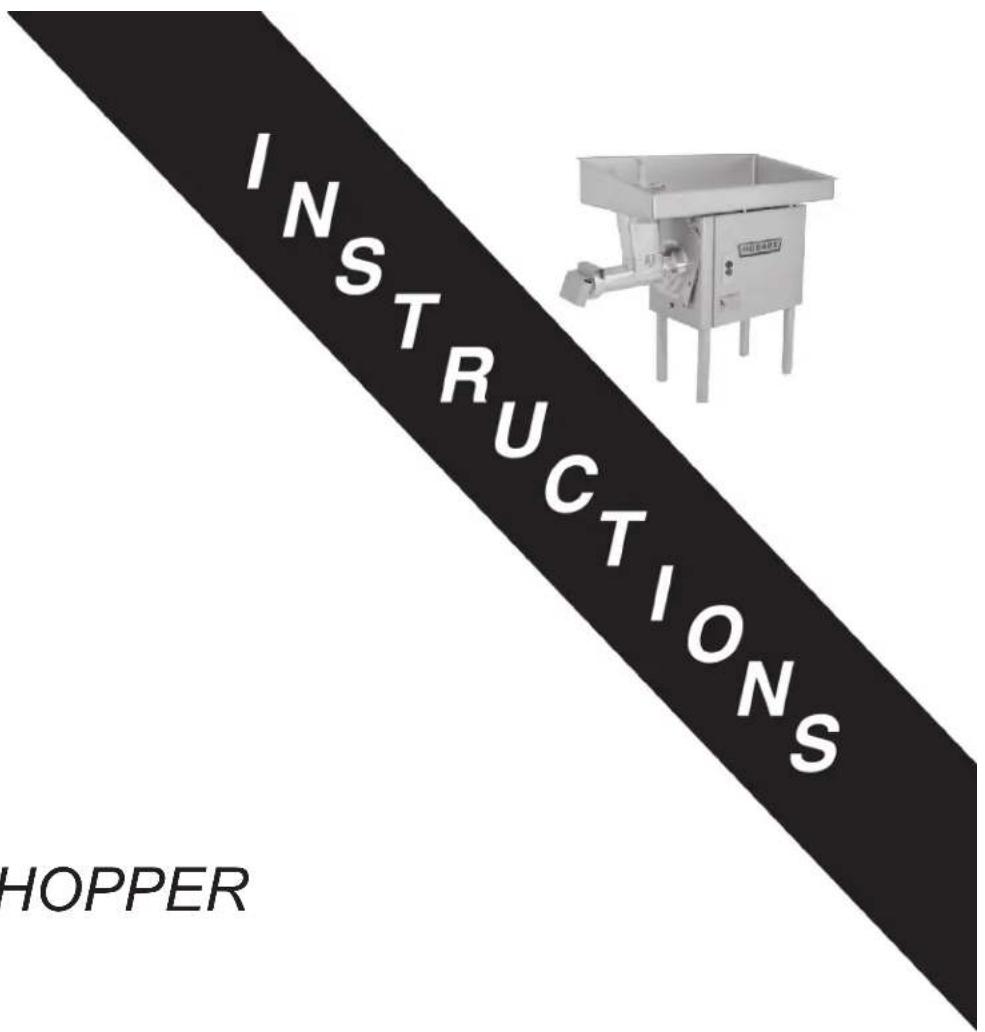
The 4146 Chopper is equipped with a 5 HP motor that rotates the worm at 215 RPM. The 4146 is designed to use a #32 size knife and plate. Knives and plates are included with the chopper.
The stainless steel or hot dipped tin feed pan on the 4146 is removable or can be tilted, so it can be easily washed at the sink or in place. Dimensions on the feed pan are 49" long x 26 ^3/4 " wide x 4 ^1/2 " deep at the front edge and 9" deep at the high back edge. A cast aluminum guard is permanently mounted to the sides of the feed pan. An electrical interlock system requires both the bowl and feed pan be in place before the machine can be turned on. The machine housing is stainless steel. This machine is a floor model with 16" legs being standard option and provides a 21 ^3/4 " clearance between the floor and the lowest point on the adjusting ring. Other leg lengths (18 ^1/2 " or 21") are also available. Sausage stuffers for hog or sheep casings are available accessories.
The chopper can grind 60 to 65 pounds of boneless beef per minute, first cut, through a ^1/8 plate. The second cut grind rate is 45 to 50 pounds per minute through a ^1/8 plate. Frozen meat must be tempered to 26^ or higher before grinding.

Fig. 1
INSTALLATION
UNPACKING
The chopper was inspected before leaving the factory. The carrier assumes full responsibility for the safe delivery upon acceptance of the shipment. Check for possible shipping damage immediately after receipt.
If the chopper is found to be damaged, complete the following steps;
- Carrier must be notified within five business days of receipt.
- Carrier's local terminal must be notified immediately upon discovery (note time, date, and who was spoken to), and follow up and confirm with written or electronic communication.
- All original packing materials must be kept for inspection purposes.
- The chopper cannot have been moved, installed, or modified.
- Notify Hobart customer care at (800) 333-7447.
Remove the carton from around the machine. Remove the machine top cover. Unscrew and save the four shipping bolts and lock washers – they are to be reused for attaching the legs to the machine.
Prior to installation, verify that the electrical service agrees with the specifications on the machine data plate.
Open the separate package containing the four legs. Assemble the adjustable leg (used for leveling) at the right rear corner when facing the rear of the machine for right-to-left operation. Assemble the non-adjustable legs at the other three corners. Replace the machine top cover. Standard mounting of the controls is on the right side of the chopper for right to left operation.
Use the spanner wrench to loosen the adjusting ring. Unscrew and remove the adjusting ring using both hands. Remove and discard the retaining washer and rubber pad used at the front of the worm where the knife and plate are to be installed.
The chopper must be thoroughly cleaned and sanitized after installation and before operation. Refer to the Cleaning section.

Fig. 2
ELECTRICAL CONNECTION
⚠ WARNING Electrical and grounding connections must comply with the applicable portion of the National Electrical Code and/or other local electrical codes.
⚠ WARNING Disconnect the electrical power to the machine and follow lockout / tagout procedures.
A 1^1/16 " diameter hole for a 3/4 " trade size conduit is located in the bottom panel. Remove access panel from the back of the unit. Refer to the machine data plate and the wiring diagram located on the machine for proper sizing of branch circuit. Upon completion, fasten the access panel in place with screws.
THREE PHASE MACHINES
Three phase machines must be connected so that the attachment drive runs counterclockwise when facing the hub. To check the direction of rotation, turn the chopper on momentarily. If rotation is not correct, DISCONNECT ELECTRICAL POWER SUPPLY and interchange any two of the incoming power supply leads. Reconnect power to the chopper. Turn the chopper on momentarily to verify correct motor rotation.
SAFETY INTERLOCK
This chopper has an interlock system that makes it inoperative with either the feed pan lifted or removed, or the bowl section of the cylinder removed. When either the feed pan or bowl is not in position, the plungers break the electrical circuit making the chopper inoperative.
OPERATION
⚠ WARNING Do not operate without guard over feed opening. Do not put hands into feed opening. Use feed stomper.
After cleaning, assemble chopper Cylinder, Bowl, Worm, Knife, Plate, Adjusting Ring, and Feed Pan as discussed in cleaning. Place the Deflector over the Adjusting Ring.
- To start the chopper, push the start button
• To stop the chopper, push the stop button
The fineness of cut depends on the hole size of the chopper Plate. The Knife and Plate must be kept clean and sharp for a fine cut. The tightness of the Adjusting Ring does not regulate fineness of cut; therefore only moderate tightness is recommended. The Adjusting Ring should be only hand-tight.
Cut the meat into chunks about the size of a fist and place in the Feed Pan. Feed meat under the guard and into the Feed Pan opening. The special high back on the Feed Pan permits the loading of large quantities of meat without spilling. Use the Feed Stomper to dislodge over-sized pieces or to dislodge meat which may become stuck in the Feed Pan opening or the Cylinder opening. It is not necessary to force meat through the chopper.
When the product is run through the chopper a second time, more speed is attained by feeding small quantities at a time. Allow the machine to feed at its own rate.
CLEANING
⚠ WARNING Disconnect the electrical power to the machine and follow lockout / tagout procedures.
The chopper should be thoroughly cleaned at the end of each day or any time it is not to be used for an extended period of time.
A heavy duty right hand feed pan is available in either tinned steel or stainless steel. The pan can be removed for cleaning in the sink or merely tilted back for in place cleaning. The tilt-back feature allows cleaning or removal of the cylinder without removing the pan from the machine. To tilt the Feed Pan, unlatch the clamps on the front of the housing and lift the end of the pan. Lift the pan rest to a vertical position (Fig. 3).

Fig. 3
After the Feed Pan has been tilted or removed, pull
the deflector straight up to remove it. Remove the bowl. Using the spanner wrench, loosen the Adjusting Ring. Unscrew and remove the Adjusting Ring with both hands. Hook the spanner wrench around the Worm stud and pull the Worm end out of the Cylinder. Remove the Knife and Plate and then the Worm. Place the removed parts in a sink for cleaning.
Using the spanner wrench, loosen but do not remove the cylinder nuts. With one hand on bottom of cylinder for support (it is heavy), turn the Cylinder clockwise and remove to a sink.
Thoroughly clean all removed parts in a sink using hot soapy water and sanitize them. The Feed Pan can either be taken to the sink or washed in the tilted position. Wipe machine housing with a damp cloth.
Prior to reassembly, apply a light coating of tasteless mineral oil to the inside of the Cylinder, the threads of the Cylinder and the Adjusting Ring, the Worm edges, the Knife and Plate and any other exposed (non-plated) metal surfaces.
To reassemble the machine, first install the cylinder by rotating it counterclockwise until the ears are under the cylinder nuts. Tighten the cylinder nuts finger-tight.
Slide the Worm into the Cylinder and rotate it to engage the square shank with the attachment drive.
With the spanner wrench, tighten the cylinder nuts.
NOTICE Do not over-tighten the cylinder nuts.
Install the Knife (cutting edges out) and the Plate. Screw the Adjusting Ring on hand-tight.
Install the bowl and deflector.
Reassemble the Feed Pan or return it to its non-tilted position.
The Feed Stomper may be stored in the throat of the cylinder.
MAINTENANCE
⚠ WARNING Disconnect the electrical power to the machine and follow lockout / tagout procedures.
LUBRICATION
The fan end bearing of the motor is grease lubricated and sealed for life of the machine. The front motor bearing is lubricated from the transmission and will not need lubricating attention.
Occasionally check the transmission lubrication level. Make sure the machine has stopped and allow time for oil to drain from the fill tube. Remove the plug button on top of the housing. Remove the dip stick and wipe off the dip stick and check to the indicator line.
Annually, or when needed, contact Hobart Service for transmission lubrication maintenance.
TROUBLESHOOTING
| SYMPTOM POSSIBLE CAUSE | |
| Chopper will not operate. Electrical power not connected. | |
SERVICE
Contact your local Hobart-authorized Service Office for any repairs or adjustments needed on this equipment.


- HOBART
- TABLE OF CONTENTS
- GENERAL 3
- INSTALLATION 4
- OPERATION....6
- CLEANING 7
- MAINTENANCE 8
- TROUBLESHOOTING 8
- Installation, Operation, and Care of 4146 Chopper
- GENERAL
- INSTALLATION
- UNPACKING
- ELECTRICAL CONNECTION
- THREE PHASE MACHINES
- SAFETY INTERLOCK
- OPERATION
- ⚠ WARNING Do not operate without guard over feed opening. Do not put hands into feed opening. Use feed stomper.
- CLEANING
- ⚠ WARNING Disconnect the electrical power to the machine and follow lockout / tagout procedures.
- MAINTENANCE
- LUBRICATION
- TROUBLESHOOTING
- SERVICE
Brand : Hobart
Model : 4146
Category : Chopper