
Acid Source ADDAC107 - Synthesizer ADDAC System - Free user manual and instructions
Find the device manual for free Acid Source ADDAC107 ADDAC System in PDF.


| Product Type | Eurorack Synthesizer Module |
| Brand | ADDAC System |
| Model | Acid Source ADDAC107 |
| Width | 9 HP |
| Depth | 4 cm (approx. 1.6 inches) |
| Power Consumption | 80 mA on +12V, 80 mA on -12V |
| VCO Frequency Range | 4 octaves (tunable via Frequency and Fine Tune knobs) |
| VCO Waveforms | Triangle or Saw (selectable), plus Square wave |
| Waveform Mix | Balance between Triangle/Saw and Square |
| Filter Types | Highpass, Bandpass, Lowpass (selectable) |
| Filter Controls | Cutoff, Resonance, and CV Attenuverter |
| VCA Envelope | AD (Attack/Decay) with very short attack and controllable decay |
| Input Gain | Amplifies external input by up to 2x, allowing saturation |
| CV Inputs | Frequency CV (with attenuator), Cutoff CV (with attenuverter), Decay CV (with attenuator) |
| CV Output | Normalled to Frequency and Cutoff inputs; also sends envelope signal |
| Accent Input | Adds to the input signal for varied amplitude |
| Audio Output | 1/8" mono jack |
| DIY Kit Available | Yes, full DIY version |
| Year Introduced | 2023 |
| Country of Design | Portugal |
Frequently Asked Questions - Acid Source ADDAC107 ADDAC System
User questions about Acid Source ADDAC107 ADDAC System
0 question about this device. Answer the ones you know or ask your own.
Ask a new question about this device
Download the instructions for your Synthesizer in PDF format for free! Find your manual Acid Source ADDAC107 - ADDAC System and take your electronic device back in hand. On this page are published all the documents necessary for the use of your device. Acid Source ADDAC107 by ADDAC System.
USER MANUAL Acid Source ADDAC107 ADDAC System
flowchart
graph TD
    A["ACID SOURCE ADDAC107"] --> B["FREQUENCY"]
    B --> C["FINE TUNE"]
    C --> D["TRI"]
    D --> E["SAW"]
    E --> F["CUTOFF"]
    F --> G["NUL SQUARE"]
    G --> H["MIX"]
    H --> I["RESO"]
    I --> J["HP"]
    I --> K["BP"]
    I --> L["LP"]
    L --> M["INPUT GAIN"]
    M --> N["VCA DECAY"]
    N --> O["FREQ. CV"]
    N --> P["CUTOFF CV"]
    N --> Q["DECAY CV"]
    O --> R["FREQ. CV"]
    P --> S["CUTOFF CV"]
    Q --> T["DECAY CV"]
    U["2023 ADDAC SYSTEM"] --> V["INPUT"]
    U --> W["ACCENT"]
    U --> X["CV OUTPUT"]
    U --> Y["OUTPUT"]
ADDAC System
Instruments for Sonic Expression Est.2009

INTRODUCING
ADDAC107
ACID
SOURCE
USER'S GUIDE, REV01
April.2023

ADDAC
System
From Portugal with Love!
DESCRIPTION
We started this module with the idea of developing a complex drum source however, somewhere along the process, we noticed how much better it performed as a synth voice and simply embraced this lucky accident.
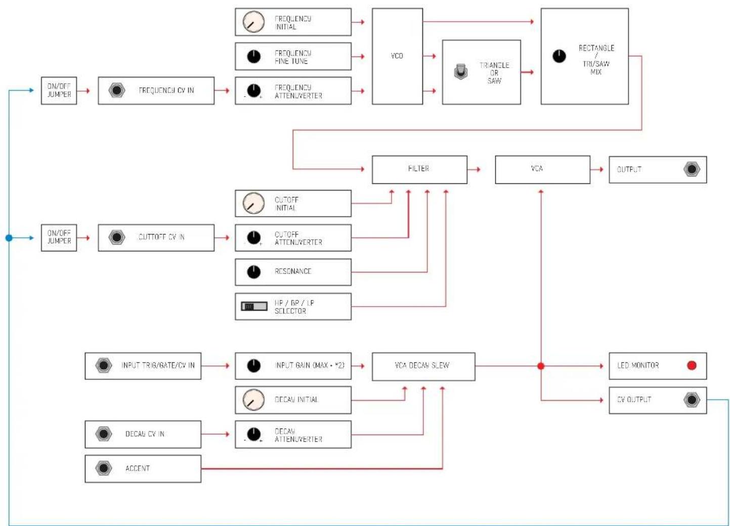
It features a VCO with a [FREQUENCY] and [FINE TUNE] knob plus a dedicated CV Input and Attenuator knob — (tunable over 4 octaves).
The VCO waveform output is achieved by selecting either a Triangle or Saw through a switch. the selected waveform can then be mixed/balanced against the square wave. The resulting mix is then sent to the Filter.
The Filter features a [CUTOFF] and [RESO] resonance knob plus a Cutoff CV Input and Attenuverter knob. A 3 position switch is used to select the filter type: Highpass, Bandpass or Lowpass. The resulting output is then sent to the VCA.
The VCA features an Input with [INPUT GAIN] knob which at maximum can amplify the incoming signal by a factor of 2. This is a very important control (more about it in the next page). It accepts any signal Trigger, Gate or CV. Whatever input is plugged in the signal is then fed through an AD with a very short attack and controllable decay through the [VCA DECA9] knob plus the CV Input and Attenuverter knob.
The resulting slewed signal is then used to control the VCA gain. This signal is also sent to the CV OUTPUT as well as the LED monitor. The Accent input adds to the Input signal creating a different amplitude output
The CV OUTPUT is also normalled to the Frequency and Cutoff inputs.

flowchart
graph TD
    A["ACID SOURCE ADDAC107"] --> B["FREQUENCY"]
    B --> C["FINE TUNE"]
    C --> D["TRI"]
    D --> E["SAW"]
    E --> F["CUTOFF"]
    F --> G["NUL SQUARE"]
    G --> H["TRI/SAW MIX"]
    H --> I["RESO"]
    I --> J["HP"]
    I --> K["BP"]
    I --> L["LP"]
    L --> M["INPUT GAIN"]
    M --> N["VCA DECAY"]
    N --> O["FREQ. CV"]
    N --> P["CUTOFF CV"]
    N --> Q["DECAY CV"]
    O --> R["0 MAX"]
    P --> S["-"]
    Q --> T["+"]
    R --> U["2023 ADDAC SYSTEM"]
    S --> U
    T --> U
    U --> V["INPUT ACCENT CV OUTPUT OUTPUT"]
This module will also be available as a full DIY kit.
Tech Specs:
9HP
4 cm deep
80mA +12V
80mA -12V
INPUT GAIN
The [INPUT GAIN] knob,
Usually Attack/Decay envelopes have a maximum voltage of +5v, no matter if the input gate is +5v or above the AD will clip at +5v. In this case we did not use this clipping method and instead allow the incoming voltage to determine the maximum AD voltage, meaning that if a +5v gate is present then the AD maximum voltage will be +5v but if a gate of +10v is sent then the AD maximum voltage will be +10v.
This also means that with higher input voltages the decay, although falling at the same speed, will be longer than with lower voltages as it has a longer range to go back to 0v.
As we mentioned before the [INPUT GAIN] knob can amplify the incoming input by a factor of 2, allowing to use a standard +5v gate or envelope and being able to make the resultant AD go up to +10v.
The AD signal is responsible for opening the VCA. Up to +5v the VCA will open to unity gain above this value the VCA will start to amplify and eventually saturate and distort.
This saturation will add harmonics to the signal which will change it's gentle timbrical nature to a more unique and peculiar timbre that will make the module shine in Acid contexts.
Adding high levels of Resonance or even filter self oscillation in combination with high VCA saturation will create even more harmonics that we highly encourage the user to explore.

flowchart
graph TD
    A["ACID SOURCE ADDAC107"] --> B["FREQUENCY"]
    B --> C["FINE TUNE"]
    C --> D["TRI"]
    D --> E["SAW"]
    E --> F["CUTOFF"]
    F --> G["π/π SQUARE"]
    G --> H["TRI/SAW MIX"]
    H --> I["RESO"]
    I --> J["HP"]
    I --> K["BP"]
    I --> L["LP"]
    L --> M["VCA DECAY"]
    M --> N["INPUT GAIN"]
    N --> O["0 MAX"]
    O --> P["0 MAX FREQ. CV"]
    P --> Q["0 MAX ACCENT"]
    Q --> R["0 MAX CUTOFF CV"]
    R --> S["0 MAX DECAV CV"]
    S --> T["0 MAX INPUT"]
    T --> U["0 MAX ACCENT"]
    U --> V["0 MAX CV OUTPUT"]
    V --> W["0 MAX OUTPUT"]
SIGNAL FLOW DIAGRAM
flowchart
graph TD
    A["ON/OFF JUMPER"] --> B["FREQUENCY CV IN"]
    B --> C["FREQUENCY INITIAL"]
    B --> D["FREQUENCY FINE TUNE"]
    B --> E["FREQUENCY ATTENUVERTER"]
    C --> F["VCD"]
    D --> F
    E --> F
    F --> G["TRIANGLE OR SAW"]
    G --> H["RECTANGLE / TRI/SAW MIX"]
    H --> I["OUTPUT"]
    I --> J["FILTER"]
    J --> K["VCA"]
    K --> L["CUTOFF INITIAL"]
    K --> M["CUTOFF ATTENUVERTER"]
    K --> N["RESONANCE"]
    K --> O["HP / BP / LP SELECTOR"]
    L --> P["CUTOFF INITIAL"]
    M --> Q["CUTOFF ATTENUVERTER"]
    N --> R["RESONANCE"]
    O --> S["HP / BP / LP SELECTOR"]
    P --> T["INPUT TRIG/BATE/CV IN"]
    Q --> U["INPUT GAIN (MAX - *2)"]
    R --> V["VCA DECAV SLEW"]
    S --> V
    T --> W["LED MONITOR"]
    U --> X["DECAY INITIAL"]
    V --> Y["DECAY ATTENUVERTER"]
    W --> Z["CV OUTPUT"]
    X --> AA["ACCENT"]
    Y --> AA
NORMALLING (SELF-PATCHED)
CONTROLS DESCRIPTION

For feedback, comments or problems please contact us at: addac@addacsystem.com



Brand : ADDAC System
Model : Acid Source ADDAC107
Category : Synthesizer