ADDAC112 - Synthesizer ADDAC System - Free user manual and instructions
Find the device manual for free ADDAC112 ADDAC System in PDF.


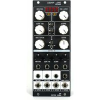
| Product Type | Eurorack Synthesizer Module |
| Brand | ADDAC System |
| Model | ADDAC112 |
| Width | 12 HP |
| Depth | 30 mm (approx.) |
| Weight | 120 g (approx.) |
| Power Supply | +12V / -12V via Eurorack bus board |
| Current Draw | +12V: 50 mA, -12V: 30 mA (typical) |
| Main Functions | Audio processing, CV control, mixing |
| Inputs | 4 x 3.5mm jacks (CV, Audio) |
| Outputs | 2 x 3.5mm jacks (Audio, CV) |
| Controls | Knobs, switches, potentiometers |
| Construction | Aluminum faceplate, PCB |
| Cleaning | Wipe with a dry, soft cloth. Do not use liquids. |
| Safety Warnings | Low voltage device. Avoid moisture and direct sunlight. Use only in Eurorack case. |
| Spare Parts & Repairability | Contact ADDAC System support. Do not attempt DIY repairs. |
| General Information | Designed and assembled in Portugal |
Frequently Asked Questions - ADDAC112 ADDAC System
User questions about ADDAC112 ADDAC System
0 question about this device. Answer the ones you know or ask your own.
Ask a new question about this device
Download the instructions for your Synthesizer in PDF format for free! Find your manual ADDAC112 - ADDAC System and take your electronic device back in hand. On this page are published all the documents necessary for the use of your device. ADDAC112 by ADDAC System.
USER MANUAL ADDAC112 ADDAC System
Instruments for Sonic Expression
Est.2009

FIRMWARE 1.0.2
WELCOME
There's a long history behind the granular concept and many reinterpretations of it's core principles, this is our take on it.
In a loose description digital Granular refer to pieces of sound files being played at the same time with slight or completely different parameters originating what is commonly referred to as granular clouds. Normally there's a buffer size from which the granular engine snips it's pieces from and plays them according to the parameters set. This buffer size is normally small in size where grains are so small that can reach the hearing spectrum and be heard as a sort of ever changing complex wavetable, this is the principle behind granular synthesis.
In our vision we added the possibility of long buffer sizes up to 5 minutes, allowing "softer" approaches to the granular principle using it as an effect that can generate from "accidental" effects like slight "stutters" to extreme processing and transformation of any incoming audio signal.
This module is conceptually deep but easy to grasp and operate as all controls are in it's dedicated panel, all jack inputs and outputs have it's own separate panel to allow no compromise when playing it's controls.
Some info stated in this document is still subject to change as new firmwares are released.
32HP 13HP
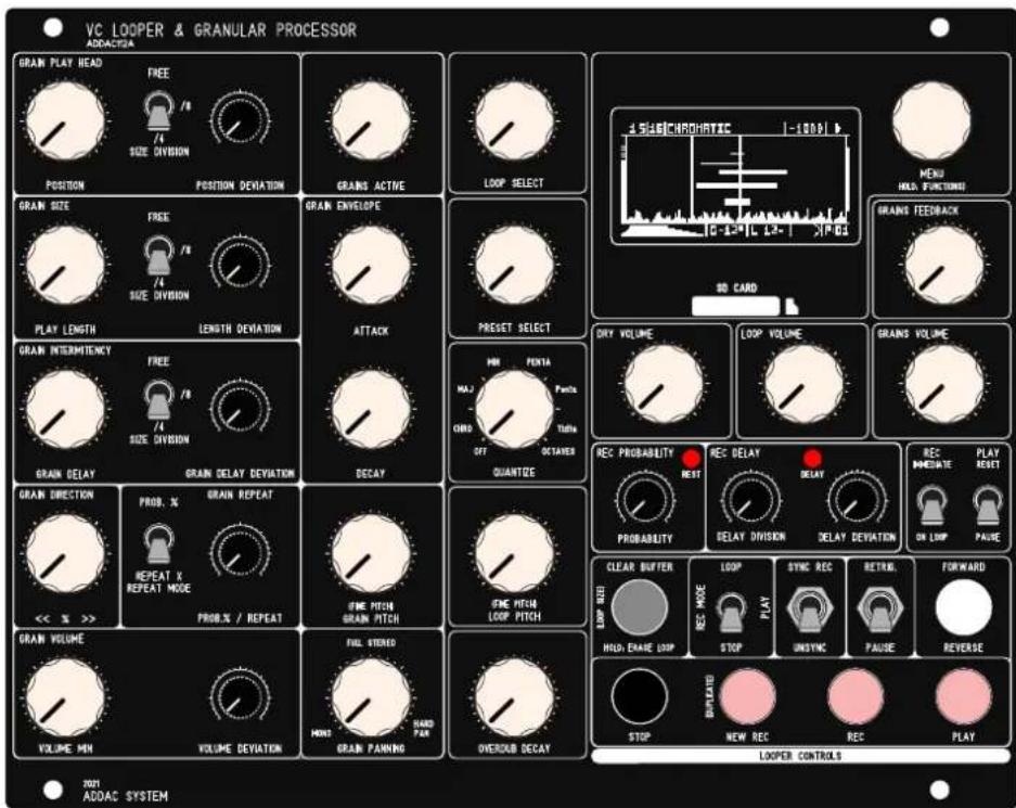

For the first time we sacrificed the module width to leave more space between controls.
DESCRIPTION
There are three main sections in this module:
Looper Engine:
The Looper is where all the Real-Time recording happens.
The audio input feeds the recording buffer, multiple controls allow to record and play loops into a list so that any sample in the list can be accessed at ay time and more acting as a standard looper
Granular Engine:
The Granular acts upon the buffer of whatever LOOP is selected.
Output Mix
The output mix allow individual control for the Dry Input, Looper Volume and Grains Volume.
Besides these main sections there's also a simple strip down MENU mainly used to LOAD and SAVE Banks, no Menu diving guaranteed.

Audio Specs:
Stereo audio input and output
32-bit floating point DSP
Bit Depth: 8 or 16bit
Sample Rates: 8Khz, 11.025Khz, 16Khz, 22.05Khz, 36Khz, 44.1Khz, 48Khz 96Khz
Tech Specs:
32HP + 13HP
4.5cm deep
240mA +12V
70mA -12V
RIBBON CONNECTIONS
!!! WARNING !!! - !!! RED STRIPE DOWN ON ALL CONNECTORS !!!
Also notice the indentation of the boxed headers!

BANKS, PRESETS and LOOPS
BANKS:
In order to make the LOAD/SAVE process simple one can only LOAD BANKS from the SD Card.
BANKS contain a list of PRESETS and a folder with a list of LOOPS.
Each BANK is saved into a folder in the SD CARD, inside the folder, together with a document containing all presets configurations, the user will find a second folder with all LOOPS in separate.WAV files.
While Saving or Loading from the SD Card the audio processing will be suspended, it may take up to 10 seconds to save a full Bank.
Once the BANK is loaded to memory jumping between LOOPS will be immediate.
A new BANK can be created at any time using the MENU: NEW BANK.
BANKS initialize with an empty list of PRESETS and LOOPS.
Each BANK stores a list of up to 99 PRESETS as well as all loops used by all these PRESETS.
Upon startup the module will automatically load the last BANK saved.
All recording is written and read from volatile memory if the BANK is not saved to the SD ard Card all data will be lost once a new BANK is loaded or power is turned off!
PRESETS:
Each PRESET contains a list of LOOPS and all Granular Settings.
Each PRESET can have shared or unique LOOP lists.
PRESETS can be saved at any time using the MENU: SAVE PRESET
PRESETS can be added to the list using the MENU: NEW PRESET, this new PRESET will be created with the current Granular settings.
As PRESETS are changed via the [PRESET SELECT] control knobs will not reflect the current values of the front panel controls and, in this case, they will seem not to have any effect, to make them effective once again the user must rotate the knob until it crosses the preset setting and then the knob will become active once again.
At all times rotating the [PRESET SELECT] to the left most position will enter preset "-" in this state all knobs always correspond to the front panel controls.
LOOPS:
A list of .WAV files up to 99 files per BANK
LOOPS can be added to a folder using a computer or recorded in real-time using the LOOPER Engine.
30Mb of maximum sampling time shared for all loops in a BANK.
Recording time will be different depending on the Sample Rate selected, as a reference at 44.1Khz will allow for 5:40 minutes (MONO) 2:50 minutes (STEREO).
Loops recorded using the module Looper Engine will either be Mono or Stereo and have the Sample Rate and Bit Depth defined by the settings chosen in the module's options menu, default setting is Stereo 44.1K 16 bit.
The total amount of recording time will depend on these 3 settings: Channels number, Sample Rate and Bit Depth.
LOOPS & PRESETS Can be Accessed in real-time with the dedicated [LOOP SELECT] & [PRESET SELECT] knobs and/or CV inputs.
If new LOOPS or PRESETS are recorded at any point in time remember that they are not yet saved to the SD Card, saving the current BANK before loading a new BANK or before power down is necessary to keep all it's contents safe in the SD Card!
SD CARD FILE STRUCTURE
At the Root of the SD Card any folder named "BANK" proceeded by a number will be eligible to be loaded. To create a new BANK directly on the SD Card simply create a new folder and name it, for example: BANK1. Next, inside this BANK1 folder, create another folder named "WAV", inside this WAV folder put any number of .wav files as long as the whole folder is below 30Mb.
Loops indexation will respect the number at the start of the file name, if no number is present the file name will be renamed by the module and a number at the start will be automatically attributed. Manually changing these numbers on a computer will change the order by which they are selected by the [LOOP SELECT].
BANK Folders are named "BANK" proceeded by a number, after the number the user can use more characters to label the bank and make it easier to identify it when loading the bank on the module. BANK naming examples below.
SD CARD STRUCTURE
- BANKO MyFirstSet
- BANK1NiceOne
- BANK2_vcoWaves
- 0.CFG
- 1.CFG
- 2.CFG
-3.CFG
- 4.CFG
- WAV
1_MYLONGFILE.WAV
2_MYSHORTLOOP.WAV
- 3_ANOTHERLOOP.WAV
- 4_ONEMOREFILE.WAV
- 5_LOOP234.WAV
- BANK3 AcousticSET
- ...
Description:
BANKO FOLDER
BANK1 FOLDER
BANK2 FOLDER
PRESET O CONFIG FILE
PRESET 1 CONFIG FILE
PRESET 2 CONFIG FILE
PRESET 3 CONFIG FILE
PRESET 4 CONFIG FILE
WAV FILES FOLDER
- 1st file in index
- 2nd file in index
- 3rd file in index
- 4th file in index
- 5th file in index
BANK3 FOLDER
...
.WAV FILES
When adding .WAV files to the SD Card from a computer it's important that the files have clean .WAV headers and no metadata, some softwares can export without adding extra data to the file. If errors are shown or if files are not loaded correctly you can always use a batch media converter like MediaHuman to automate and make this task a simple process:
https://www.mediahuman.com/download.html
DEVIATION
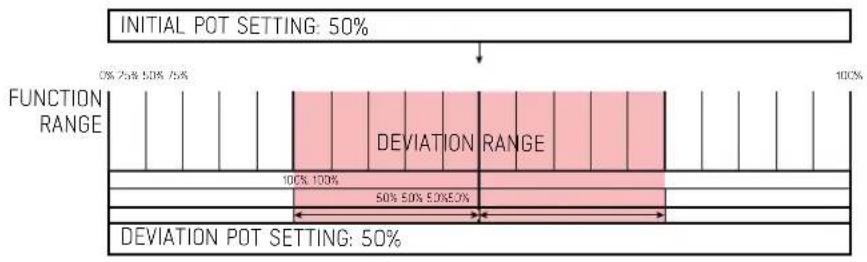
DEVIATION is used throughout this guide to refer to a deviation from the Initial knob. Deviation is a random function kept inside a range based on a percentage spread centered on the Initial knob setting. This keeps all random values inside the main range of the knob never going above or below the range limits eliminating "dead spots".
The examples below will graphically exemplify this concept:


SIGNAL FLOW DIAGRAM

flowchart
Electrical system block diagram showing granular, audio stored, and lower section connections with component labels and signal paths.LOOPER ENGINE
The Looper section is where all Recording action happens.
It can record up to 99 LOOPS per PRESET
LOOPS are recorded in a list and selectable with the [LOOP SELECT] Knob or CV input
The Looper playback volume is set using the [LOOP VOLUME] KNOB or CV input
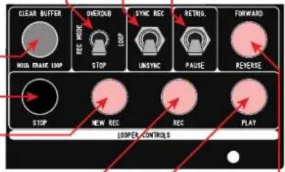
SWITCHES SETTINGS:
[RETRIG. / PAUSE] determines how PLAY works while already playing the LOOP
[RETRIG.] Pressing PLAY while retrigger the LOOP from the start
[PAUSE] will toggle between Play and Pause states
[SYNC REC / UNSYNC] determines how the Recording Head works
[SYNC REC] Rec Head follows the Play Head.
[UNSYNC] Independent Rec Head.
[REC MODE] : [OVERDUB / LOOP / STOP] determines what happens when finishes recording
[OVERDUB] records continuously in a loop
[LOOP] finishes recording and starts playback
[STOP] finishes recording and stops playback
[STOP] mode will also stop playback at the end of the loop to
allow "One Shot" loop playback
LOOPER PUSH-BUTTON CONTROLS:
[CLEAR] Clears the Entire LOOP buffer - Long Press erases LOOP from list.
[STOP] Stops playback or recording
[REC NEW] Starts recording a new LOOP and adds it to the list.
[REC] Records on the current LOOP buffer.
[PLAY] Play / Pause / Retrigger the current LOOP
[FORWARD/REVERSE] determines the playback direction

flowchart
graph TD
    A["LOOPER INITIALIZATION"] --> B["PRESS NEW REC or REC"]
    B --> C["START S RECORDING"]
    C --> D["PRESS REC NEW"]
    C --> E["PRESS REC"]
    C --> F["PRESS PLAB OR STOP"]
    D --> G["SAVES RECORDED LOOP AND STARTS RECORDING NEW LOOP"]
    E --> H["LOCKS LOOP LENGTH AND STOPS RECORDING"]
    F --> I["LOCKS LOOP LENGTH AND KEEPS RECORDING FROM THE START POINT"]
LOOPER ENGINE
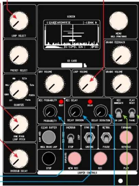
LOOPER CONTROLS:
[LOOP VOLUME] sets the LOOP playback overall volume.
[LOOP SELECT] Determines which LOOP to play from the list in the current PRESET.
[LOOP PITCH] Determines the buffer playback rate setting the Pitch of the Loop from -2 to +3 octaves. The QUANTIZE Settings will influence this setting.
[OVERDUB DECAY] while recording in Overdub mode, determines the amount of the previous buffer content to be kept in the new buffer.
CONTINUOUS RECORDING SETTINGS:
Continuous recording is vital to apply a granular effect to an incoming audio source, adding some indeterminancy to the recording timing can create very interesting results we added two methods for this. Probability and Delay.
RECORDING PROBABILITY:
[REC PROBABILITY] Determines the probability that the recording will happen.
Recording is happening in a loop depending on the probability set here it will either record through the buffer or will REST and go through the buffer without recording at the end of the buffer it will calculate the new probability and record or rest for the next buffer period.
RANGE: 0 to 100%
RECORDING DELAY:
[DELAY DIVISION] Determines the amount of delay to pause for upon reaching the end of the buffer, meaning the continuous recording will pause at every recording loop for a multiple of 1/32 of the buffer length.
The DELAY led will light up while in this recording delay state RANGE: 1 to 32
[DELAY DEVIATION] sets the amount of deviation from the [DELAY DIVISION] setting.
RANGE: 0 to 100%
REC/PLAY MODES & ON LOOP CHANGE SETTINGS:
These options are shared for REC/PLAY modes as well as to define what happens whenever a new LOOP is selected using the [LOOP SELECT] knob or CV input.
[IMMEDIATE / ON LOOP]
REC: Determines if whenever a Recording is enabled it will start recording immediately or when the Play head crosses the end of the loop point and start recording from the beginning of the loop.
ON LOOP CHANGE: Determines if the new selected LOOP plays immediately after being selected or if it waits for the current LOOP to reach the end point and then make the LOOP change.
[RESET / PAUSE]
PLAY: Determines if when PLAY is engaged the loop will start from it's current position or if it resets to it's start position.
LOOPER ENGINE (SPECIAL FUNCTIONS)
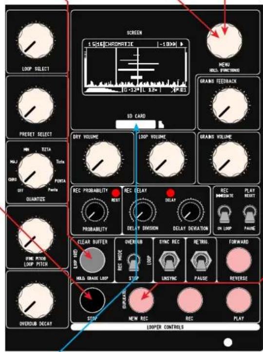
COPY LOOP
Loops can be duplicated by pushing and holding the [MENU] encoder button and then press [NEW REC].
The copied loop will appear at the last position in the loop index.
A message will appear stating: LOOP DUPLICATED
CHANGE LOOP SIZE:
The loop size can be changed by pushing and holding the [MENU] encoder button and then press [CLEAR BUFFER].
A menu will appear to select the size in samples, it will also display the time in milliseconds and BPM.
Pressing the [MENU] button after changes are made will save the new length. A message will appear stating: LOOP RESIZED
A long press of the [MENU] button will exit the menu without changes.
CLOCKED MODE:
In Clocked Mode the Stop Button and respective trigger input ill work as a Clock Input.
Clocked Mode changes the way the Looper Engine push buttons works. In this mode buttons [NEW REC] [REC] [PLAY] [FORWARD/REVERSE] (and their dedicated trigger inputs) instead of executing the actions immediately they will engage once activated (shown by blinking) and will only execute when the [STOP] button is pressed or a trigger on the Stop Trigger input is detected.
This way a clock input can be plugged in the Stop Trigger Input and all other Looper push buttons will be synced to the incoming clock, quantizing the timing of the user actions to the incoming clock.
SD CARD
SD CARD:
Any SD Card can be used, faster SD Cards will save/load Banks faster. SD Cards should be formatted in FAT16 format.
You can remove/insert an SD Card at any time.
GRANULAR ENGINE
Our Granular Engine features a deep set of controls to allow a wide range of results. It was designed to be fully hands-on and have all controls available in the front panel. Only minor settings were left in the menu alongside with Save/Load functions.
After the Grain is initialized (by adding a new grain or at startup) the engine will read and calculate all parameters. Once initiated grains play continuously calculating new settings every times it starts playing.
The Granular Engine feeds from whatever LOOP buffer is selected, hence the size of any grain is dependent of the LOOP size
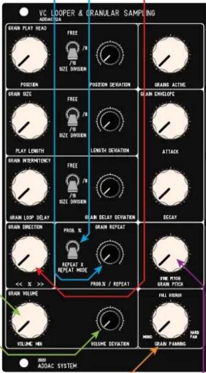
GRAINS ACTIVE:
[GRAINS ACTIVE] Determines how many grains are being played at once Range depends on the the SAMPLERATE and LOOP PITCH MODE options
GRAIN PLAY HEAD:
[POSITION] will determine the grain Start Point: RANGE: 0-32
[SIZE DIVISION] : [FREE/8/16] will add a time quantization to the LOOP Buffer [16] will divide the LOOP by 8 playing only from these start points [8] will divide the LOOP by 4 playing only from these start points [FREE] will apply no division
[POSITION DEVIATION] will determine the deviation to the Start Point: RANGE: 0-100%
GRAIN SIZE:
[PLAY LENGTH] will determine the length of the grain: RANGE: 0-100%
[SIZE DIVISION] : [FREE/8/16] will add a time quantization to the Length [16] the length will always be multiples of 1/16v of the LOOP Length [8] the length will always be multiples of 1/8 of the LOOP Length [FREE] will apply no division
[LENGTH DEVIATION] will determine the deviation to the Play Length: RANGE: 0-100%
GRAIN INTERMITENCY:
[GRAIN LOOP DELAY] will determine the length of the delay (wait in silence) after the grain finishes playing and before it plays again:
[SIZE DIVISION] : [FREE/8/16] will add a time quantization to the Delay [16] the delay will always be multiples of 1/16 of the LOOP Length [8] the delay will always be multiples of 1/8 of the LOOP Length [FREE] will apply no division and set range from 0 to 5 seconds
[LENGTH DEVIATION] will determine the deviation to the Delay applied above: RANGE: 0-100%

GRANULAR ENGINE
GRAIN DIRECTION:
[GRAIN DIRECTIONS] Sets the probability of the Grain Play Direction (Forward/Reverse) Full Left only plays in Reverse, Full Right only plays Forward
GRAIN REPEAT:
Grain Repeat will determine if the sample plays with the exactly same setting as the previously time played or if it calculates new parameters. There are 2 modes selected by the [REPEAT MODE] switch
[REPEAT MODE] : [PROBABILITY / REPEAT X] there are 2 Modes for this feature [PROBABILITY] sets the probability of repeat: 0 to 100% [REPEAT X] repeats the grain for X times: 0 to 16
[PROB.% / REPEAT] sets the value for the Mode selected.
GRAIN VOLUME:
[VOLUME MIN] sets the Minimum Volume for the grains
[VOLUME DEVIATION] sets the amount of deviation from the Minimum Volume.
GRAIN PANNING:
[GRAIN PANNING] sets the Panning Probability based on the behaviour pictured below

bar
| Grain Panning Position | Percentage | | ---------------------- | ---------- | | LEFT | 50% | | MONO | 50% | | RIGHT | 50% |GRAIN PITCH:
[GRAIN PITCH] setting for the Grains Pitch: from -2 to +3 octaves
GRANULAR ENGINE
GRAIN ENVELOPE:
Envelope is applied throughout the full length of the grain to be played
[ATTACK] sets the Attack percentage
[DECA9] sets the Decay percentage
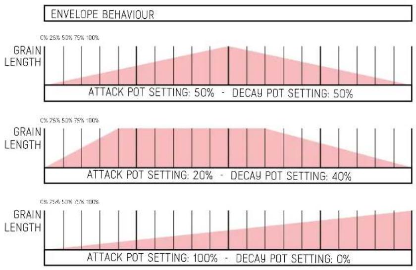
To summarize here's a diagram showing the working method:

flowchart
graph TD
    A["GRAIN INITIALIZATION"] --> B["CALCULATE PARAMETERS"]
    B --> C["PLAYS GRAIN"]
    C --> D["INTERMITENCY SILENCE DELAY"]
    D --> E["NO YES REPEAT GRAIN"]
    E --> B
    F["GRAIN POSITION\nGRAIN LENGTH\nPLAY DIRECTION\nPITCH\nENVELOPE\nVOLUME\nPANNING\nINTERMITENCY DELAY"] --> B
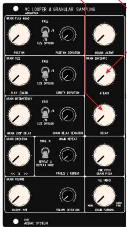
AUDIO INPUTS, OUTPUTS & FEEDBACK
INPUTS:
There are 2 input pairs on ADDAC112B:
2 Mono inputs at Synth Level (IN 1 is normalled to In 2)
1 Stereo input at Line Level
These inputs are mixed to a Stereo signal after which the [INPUT GAIN] knob sets the final gain sent to the Looper Engine.
An Led acts as a visual display for the level set. All inputs are also mixed down to a mono signal available at the [INS MONO OUT] jack
MAIN OUTPUTS MIX:
The Master Outputs sums the Looper and Granular Engine together with the Dry signal into a Stereo Output.
[DRY VOLUME] Sets the volume for the DRY Input into the Outputs.
[LOOP VOLUME] sets the volume for the LOOPER Engine into the Outputs.
[GRAINS VOLUME] sets the volume for the Granular Engine into the Outputs.
[GRAINS FEEDBACK] Sets the volume of the Granular Engine Mix sent into the Looper Audio Input
There are 3 physical outputs for the Main Mix:
Left Output
Right Output
Mono Output (L+R)

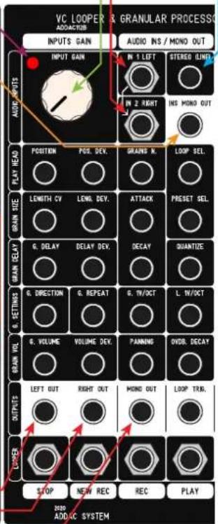
CV & TRIGGER INPUTS
All of the front panel Control Knobs have their own CV Input
All Controls on the left block can be found in the same matrix configuration on the Inputs Module

All Controls on the right block can be found vertically from the top right corner All Trigger inputs for the Looper controls can be found at the bottom of the module
The [CLEAR BUFFER] control is the only push button without a Trigger input. Encoder and Toggle switches have no CV inputs.

OLED MONITOR
MAIN SCREEN:
The Main Screen shows the most important info for overall operation.
LOOPER STATE
Shows REC / PLAY / PAUSE / STOP states
INPUT VOLUME MONITOR
A real-time input level monitoring in decibels, above -2db the colors will invert to represent clipping
QUANTIZATION SCALE
Scale selected
GRAINS ACTIVE
Number of active Grains
MONO/STEREO INDICATOR
S = Stereo file
M - Mono file
LOOP SELECTED
The current loop being played
GRAINS VOLUME & DEVIATION
The white bar shows the [VOLUME MIN] setting The traces on top shows the maximum random set by [VOLUME DEVIATION]
WAVEFORM REPRESENTATION
Low resolution representation of the waveform
ATTACK & DECAY
Grains envelope representation
GRAINS PITCH
The current grains pitch, the small rectangle at the end shows the cents difference from the perfect note
LOOP PITCH
The current loop pitch, the small rectangle at the end shows the cents difference from the perfect note
GRAIN DIRECTION
PRESET SELECTED
GRAINS PANNING
The vertical bar represents the stereo field, the white area(s) show the range of the randomization applied to the grains panning

OLED MONITOR
PLAY HEAD
Shows the current position of the playback head
RECORDING HEAD
Shows the current position of the recording head
GRAINS LENGTH
Second vertical bar shows the setting defined by [LENGTH]
GRAINS POSITION
First vertical bar shows the setting defined by [POSITION]
GRAINS DISPLAY
Represents all active grains
Length in the X axis
Panning in the Y axis
Volume in thickness

OLED MONITOR (SPECIAL FUNCTIONS)
SMALL DOT
Whenever this dot appears it means that the loop selected is either not saved in the SD Card or it has been changed since it was loaded from the SD Card
LOOP SELECTED WHITE AREA
This color inversion will be shown whenever the loop selected ahs change but it will only change when the previous loop reaches it's end.
INPUT VOLUME MONITOR WHITE AREA
Whenever the input volume goes above -5db it will invert the colors to show it's close to clipping.
15|16|CHROMATIC | -10DB
1516|CHROMATIC |-1008
15|16|CHROMATIC -5DB
INFO SCREEN
Rotating the [MENU] encoder at any point while on the main screen leads you into the info screen, this will show the current configuration general settings:
Stereo or Mono Recording
Sample Rate
Bit Depth
Current Bank
Number of Loops in current Bank
Selected Loop duration in seconds
Free Memory in seconds
Master Out dB meter

Pressing the [MENU] button while on this page exits to the main screen
MENU
MENU
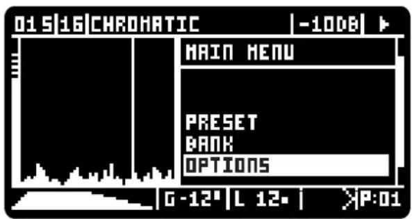
Pressing the [MENU] button shows the main menu window: A long press of the [MENU] button exits whichever Menu without making changes
PRESET:
NEW - Adds a new preset to the Presets list with the current settings UPDATE - Updates the current preset to the current settings ADD LOOPS - Presets also store a selective list of loops, this updates the current preset loop list to all loops available in memory
BANK:
NEW - Creates a new empty Bank LOAD - Loads a Bank from the SD Card SAVE - Saves a bank to the SD Card
OPTIONS SUBMENU PAGE 1
MONO/STEREO:
Sets the Looper Engine for Mono or Stereo Recording
SAMPLERATE:
The heart of the module: global samplerate setting: 8Khz, 11khz, 16Khz, 22khz, 32Khz, 44.1khz, 48khz, 96khz
BIT DEPTH:
The bit depth resolution: 16 Bit 8 Bit
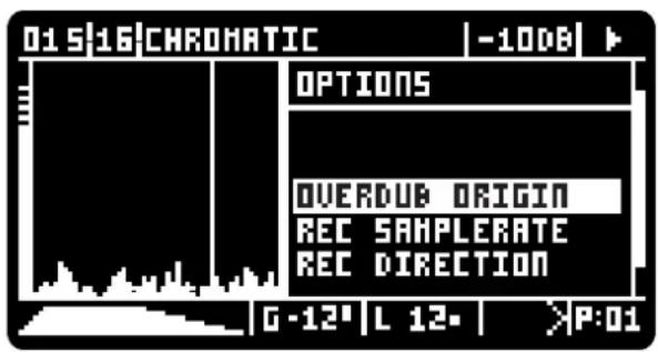
OPTIONS SUBMENU PAGE 2
OVERDUB ORIGIN:
PLAY HEAD - Overdub comes from the Play Head position REC HEAD - Overdub comes from the Rec Head position BOTH - Overdub comes from the Both Heads positions
REC SAMPLERATE:
FIXED - Recording at the PAGE1:SAMPLERATE setting VARIABLE - Recording samplerate varies according to the playback pitch
REC DIRECTION:
DISABLED - Rec Head always goes forward and ignores [FORWARD/REVERSE] button ENABLED - Rec Head follows [FORWARD/REVERSE] button

MENU
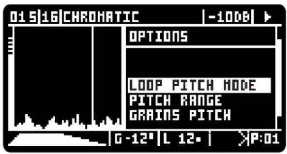
OPTIONS SUBMENU PAGE 3
LOOP PITCH MODE:
SAMPLERATE- Pitch shifting using sample rate change
PITCH SHIFTING - Changes pitch without changing the loop length
TIME STRETCHING - Changes the loop length without changing pitch
PITCH/TIME - Changes Pitch and Length as in SAMPLERATE
PITCH AND TIME - Independent control of loop Pitch and Length
PITCH RANGE:
Pitch ranges can vary to have more pitch control over smaller ranges.
1v/oct is only respected on the first option!
-24 +36 : -2 to +3 octaves
-12 +12 : -1 to +1 octaves
-2 +2 : -2 to +2 semitones
-INF +24 : from stop to +2 octaves
GRAINS PITCH:
When either the [GRAIN PITCH] knob is moved or a new CV is detected the grains pitch can be set to:
KEEP - each grain keeps the initial pitch until the end of it's length
CHANGE - immediately changes the pitch of all grains at once
OPTIONS SUBMENU PAGE 4
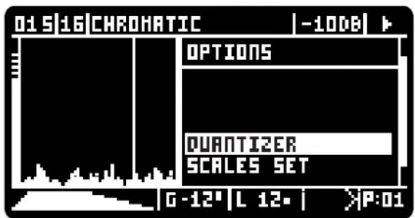
QUANTIZER:
BOTH - Applies quantization to both the Looper and the Grains Engines
LOOPS ONLY - Only applies quantization to the Looper Engine GRAINS ONLY - Only applies quantization to the Grains Engine
SCALES SET:
DEFAULT - Default quantization scales
CUSTOM - custom quantization scales
MENU
OPTIONS SUBMENU PAGE 5
PAUSE MODE:
TOGGLE - toggles between pause and play
MOMENTARY - pauses while button is pressed or GATE Input is On
CLOCKED MODE
Clocked Mode is one of the Looper Special Functions described in page 10. to activate select ON.
TRIGGER SIZE:
The length of both trigger outputs in milliseconds
1 MS
10 MS
OPTIONS SUBMENU PAGE 6
UPDATE FIRMWARE:
Pressing this option will suspend the module operation and enter DFU mode waiting for the new firmware to be uploaded.
The module will only recover from this state after the new firmware was uploaded or by powering it down and back up again.


LOOPER ENGINE PITCH SHIFTING MODES
There are 4 different Pitch Modes available for the Looper Engine:
Samplerate:
Uses a simpler sample rate change approach to change the pitch, in this mode the loop length is also affected by the pitch.
Pitch Shifting:
This mode only changes Pitch without changing the loop length
Time Stretching
This mode only changes the loop length without changing the pitch
Pitch/Time:
This mode changes both the Pitch and Loop length, similar to the Samplerate option but using the Pitch Shifting/Time Stretching methods.
Pitch and Time:
This mode separately changes both the Pitch and Loop length. When this mode is selected the [LOOP PITCH] controls the pitch and [REC DELAY DEV.] controls the time stretching. The Rec Delay Deviation function becomes inactive but the [REC DELAY] is still active.
The Granular Engine always use the Samplerate method.
QUANTIZATION
QUANTIZATION
There are 7 scales slots and a fixed OFF Position.
The 7 Slots can be customized to any ratio by the user.
Inside MENU > OPTIONS > SCALES SET the user can choose between DEFAULT and CUSTOM scales:
DEFAULT are the default scales written on the front panel.
CUSTOM are user customized scales
We decided to leave both of these scales open to customization to an overall number of 14 scales.
QUANTIZATION SCALES FILE:
Every BANK folder has a SCALES.CFG file, this file contains all scales ratios and can be edited in a simple text editor.
For anyone not used to programming this file will look a bit criptic and remember it is important to keep it tidy with all the brackets, commas and other punctuation elements in their correct place.
FILE STRUCTURE:
This is the file structure, you can see that there are repeated blocks for each of the slots, the user should only edit the ratios list and the name inside the quotation marks, for example the chromatic scale name:
"name": "chromatic",
would be changed to:
"name": "my custom scale",
Make sure to keep all commas in their place!
Scales are not limited to 12 notes per octave, the user can add as many ratios as notes wanted.
SCALE MODES:
There's a final setting at the end of each scale ratios titled "per_octave", this setting can only be set to true or false:
"per_octave": true
used for any set of ratios to be repeated across octaves, so every ratio is present in every octave.
"per\_octave": false
used for any scale that does not respect octaves, ratios will not be repeated. There will be as much notes as ratios included.
for example this is the Harmonic Series setting:
"name": "harmonic",
"ratios": [
    1.
    2.
    3.
    4.
    5.
    6.
    7.
    8.
    9.
    10.
    11.
    12.
    13.
    14.
    15.
    16
].
"per_octave": false

"Default Scales": [
{
    "name": "chromatic",
    "ratios": [
    1,
    1.059460044,
    1.122460008,
    1.189210057,
    1.259920001,
    1.334830046,
    1.414209962,
    1.49830997,
    1.58739996,
    1.681789994,
    1.781800032,
    1.88775003
    ],
    "per_octave": true
},
{
    "name": "major",
    "ratios": [
    1,
    1.122460008,
    1.259920001,
    1.334830046,
    1.49830997,
    1.681789994,
    1.88775003
    ],
    "per_octave": true
},
(A LOT MORE HERE)
} ]
FIRST STEPS
First let's create a new empty BANK
Press the Menu Encoder and the Menu will appear on the screen, select BANK then select NEW
We now have a new empty Bank in volatile memory
Everything done from now on will not be saved it you turn the module off, when you're happy or ready to power down open the Menu, select BANK and then SAVE, this will save all the contents of the BANK to the SD CARD and will be loaded upon startup.
Set the [INPUT GAIN] until you see some LED activity and bring the [DRY VOLUME] knob up to hear the incoming audio
![Next let's record our first loop. Notice the Loop index displays "-" - No Loops Press [NEW REC] or [REC] when you're happy with the length of the loop press one of the following: [REC] enters Overdub Mode [PLAY] Stops recording and enters Playback Mode [STOP] Stops recording and playback Now the Loop index will display "1"](/content/2026/06/1403311/images/3522e70c5a668609c1cc90a2caf5c026713cc94bc5428b2b9f80b7eece91fd8d.jpg)
Let's record a second loop,
Press [NEW REC] followed by [PLAY] when you're happy with the length of the loop, this will stop recording and start Playback.
Notice the Loop index will display "2"
Bring the [LOOP VOLUME] knob up to hear the loop playback
To be less confusing bring the [DRY VOLUME] knob down to hear only the loop playback
Now you can use the [LOOP SELECT] knob to switch between loop 1 and 2
You can also use the [LOOP PITCH] knob to adjust the playback samplerate
Now let's process the loop playing through the granular engine,
Bring the [GRAINS VOLUME] knob up to hear the grains playback and use the control knobs as defined before to get
to an overall setting that you're happy with
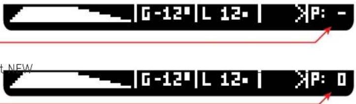
Now le'ts create a Preset,
Notice the PRESET index displays "-" = No Presets
Press the [MENU] encoder, select PRESETS and then select NEW
This will generate Preset number 0 (zero)
Now le'ts create a second Preset,
Use the control knobs once again to change the granular settings and then press the [MENU] encoder, select
PRESETS and then select NEW
This will generate Preset number 1

Now you can use the [PRESET SELECT] knob to switch between preset 0 and 1
Next let's save this Bank with all it's loops and presets.
press the [MENU] encoder, select BANK and then select SAVE, audio playback will stop at this point and will resume as soon as it finishes saving all the data to the SD CARD. Once all data is saved a message will appear on the screen.
You can now switch off the module all the data is safe.
For convenience the last Bank saved will be automatically loaded on startup.
FIRMWARE UPDATE
To update the firmware you need to detach the 112A from your frame but leave the ribbon power cable connected and the Power ON. Once lifted from the frame locate the Micro USB input between the two pcbs on the right side of the module. Plug a cable to it and to your computer.
- Download and unzip this .hex file: https://media.addacsystem.com/firmwares/ADDAC112_firmware.zip
- On the module press encoder > options > update FW
- Using the Chrome browser go here: (You will need an up-to-date version of Chrome, at least version 61 or newer) https://electro-smith.github.io/Programmer/
- Press the "Connect" button and, from the options, choose the one called "DFU in FS Mode" (ignore platform and example drop menus)
- Press "Choose file" and choose the downloaded firmware .hex file.
- Press "Program" and it will show some progress bars on the browser
- Once finished disconnect the USB cable and restart the module
Notice the new firmware revision on the startup screen.
Happy patching!
For feedback, comments or problems please contact us at: addac@addacsystem.com



- WELCOME
- DESCRIPTION
- RIBBON CONNECTIONS
- BANKS, PRESETS and LOOPS
- BANKS:
- PRESETS:
- LOOPS:
- SD CARD FILE STRUCTURE
- SD CARD STRUCTURE
- Description:
- .WAV FILES
- DEVIATION
- LOOPER ENGINE
- SWITCHES SETTINGS:
- LOOPER PUSH-BUTTON CONTROLS:
- LOOPER CONTROLS:
- CONTINUOUS RECORDING SETTINGS:
- RECORDING PROBABILITY:
- RECORDING DELAY:
- REC/PLAY MODES & ON LOOP CHANGE SETTINGS:
- [IMMEDIATE / ON LOOP]
- [RESET / PAUSE]
- LOOPER ENGINE (SPECIAL FUNCTIONS)
- COPY LOOP
- CHANGE LOOP SIZE:
- CLOCKED MODE:
- SD CARD
- SD CARD:
- GRANULAR ENGINE
- GRAINS ACTIVE:
- GRAIN PLAY HEAD:
- GRAIN SIZE:
- GRAIN INTERMITENCY:
- GRAIN DIRECTION:
- GRAIN REPEAT:
- GRAIN VOLUME:
- GRAIN PANNING:
- GRAIN PITCH:
- GRAIN ENVELOPE:
- AUDIO INPUTS, OUTPUTS & FEEDBACK
- INPUTS:
- MAIN OUTPUTS MIX:
- CV & TRIGGER INPUTS
- OLED MONITOR
- MAIN SCREEN:
- LOOPER STATE
- INPUT VOLUME MONITOR
- QUANTIZATION SCALE
- GRAINS ACTIVE
- MONO/STEREO INDICATOR
- LOOP SELECTED
- GRAINS VOLUME & DEVIATION
- WAVEFORM REPRESENTATION
- ATTACK & DECAY
- GRAINS PITCH
- LOOP PITCH
- GRAIN DIRECTION
- PRESET SELECTED
- GRAINS PANNING
- PLAY HEAD
- RECORDING HEAD
- GRAINS LENGTH
- GRAINS POSITION
- GRAINS DISPLAY
- OLED MONITOR (SPECIAL FUNCTIONS)
- SMALL DOT
- LOOP SELECTED WHITE AREA
- INPUT VOLUME MONITOR WHITE AREA
- INFO SCREEN
- MENU
- PRESET:
- BANK:
- OPTIONS SUBMENU PAGE 1
- MONO/STEREO:
- SAMPLERATE:
- BIT DEPTH:
- OPTIONS SUBMENU PAGE 2
- OVERDUB ORIGIN:
- REC SAMPLERATE:
- REC DIRECTION:
- OPTIONS SUBMENU PAGE 3
- PITCH RANGE:
- GRAINS PITCH:
- OPTIONS SUBMENU PAGE 4
- OPTIONS SUBMENU PAGE 5
- CLOCKED MODE
- TRIGGER SIZE:
- OPTIONS SUBMENU PAGE 6
- LOOPER ENGINE PITCH SHIFTING MODES
- QUANTIZATION
- QUANTIZATION SCALES FILE:
- FILE STRUCTURE:
- SCALE MODES:
- "per\_octave": false
- FIRST STEPS
- FIRMWARE UPDATE
Brand : ADDAC System
Model : ADDAC112
Category : Synthesizer