
ADDAC507 - Synthesizer ADDAC System - Free user manual and instructions
Find the device manual for free ADDAC507 ADDAC System in PDF.


| Product Type | Eurorack synthesizer module |
| Brand | ADDAC System |
| Model | ADDAC507 Random Bézier Waves |
| Main Function | Dual random voltage generator with Bézier interpolation, evolving LFO-like modulation |
| Form Factor | 10HP wide Eurorack module |
| Depth | 4.5 cm |
| Power Consumption | +12V: 70 mA, -12V: 40 mA |
| Controls per Channel | Frequency, Level (attenuator/VCA), Offset (±5V), Curve (Bézier shape), Limit/Fold/Thru clip mode |
| CV Inputs | Frequency and Level each with attenuverter; internally normalized to the other channel's main output |
| Outputs | Wave, Inverted Wave, Gate (channel A: trigger at each random step; channel B: comparator), Average (A+B)/2, Inverted Average |
| Special Features | Bézier interpolation with adjustable control points; cross-patching via internal normalization; jumper-disablable normalization on rear PCB |
| Clip Modes | Limit (clamps at ±5V), Fold (wavefolds, doubles voltage range), Thru (inverts and appears at opposite polarity) |
| LED Indicators | Monitors per-channel voltage and gate outputs |
| Collaboration | Designed with Monotrail (Rijnder Kamerbeek) |
| Country of Origin | Portugal |
| Maintenance | Wipe with a dry cloth; avoid liquids and abrasive cleaners |
| Safety | Compliant with Eurorack standards; use only with Eurorack cases and power supplies |
| Reparability | Contact ADDAC System support for issues; internal jumpers allow disabling normalization; no user-serviceable parts beyond jumper manipulation |
| Manual | Free PDF available from ADDAC System website |
Frequently Asked Questions - ADDAC507 ADDAC System
User questions about ADDAC507 ADDAC System
0 question about this device. Answer the ones you know or ask your own.
Ask a new question about this device
Download the instructions for your Synthesizer in PDF format for free! Find your manual ADDAC507 - ADDAC System and take your electronic device back in hand. On this page are published all the documents necessary for the use of your device. ADDAC507 by ADDAC System.
USER MANUAL ADDAC507 ADDAC System
Instruments for Sonic Expression
Est.2009
INTRODUCING
ADDAC507
RANDOM
BÉZIER
WAVES
USER'S GUIDE. REVO1
March.2024
A collaboration with:
MONOTRAIL
ADDAC
System
From Portugal with Love!
WELCOME
This module started with an idea from Rijnder Kamerbeek aka Monotrail, a straightforward random generator with interpolation between random points making it something like a complex, ever evolving. LFO
The concept is simple. It contains two identical smooth random voltage generators. Each has a frequency, level, offset and curve control. The frequency control sets a steady pace with which bipolar random voltages are generated. The level control works like an attenuator/VCA on the output, reaching from max output to closed. The offset allows shifting the whole wave up and down on the voltage range. Curve determines the shape of the interpolation. The bipolar activity on the main outputs as well as gate outputs are visualised with LEDs.
Both Frequency and Level controls have a CV input with attenuator. When there is nothing patched into the CV inputs, these are internally connected to the main output of the other channel. This normalization makes it very easy to add randomization to the frequency or level for more depth, or of course, add cross-modulation for chaotic voltages.
The output VCAs are useful to dial in subtle and time-based modulation without the need for external VCAs. For example, to modulate the amount over time with an envelope, or use the other generator with slower speeds to add random changes to the level of a random voltage.
Both generators also have two other outputs. One is an exact inversion of the main output, so it responds to the level and CV input. This is great for stereo or inversed effect patches. The other is a simple pulse output, here there are two different behaviours, channel A outputs a pulse at every random generation, channel B acts like a comparator. Whenever the main is positive this comparator output is a high gate. And whenever the main output is negative or close to 0, there is no gate output. Great for random triggers or firing other events like envelopes.
A couple other outputs are also available and are obtained by averaging both channel main outputs. The first output is the average while the second is an inverted average.
CHANNEL A CHANNEL B

Tech Specs:
10HP
4.5cm deep
70mA +12V
40mA -12V
CONTROLS DESCRIPTION

line
| Frequency Cycle | Value | | --------------- | --------- | | Current Value | -5v | | Next Value | 0v |[LEVEL] sets the voltage output range, with a maximum range of ±5V
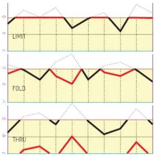
[LIMIT/FOLD/THRU] sets what happens when the voltage hits the maximum range:
LIMIT: limits the value to the maximum ±5v
FOLD: folds the voltage like a standard wavefolder. In this setting the output voltage range is multiplied by 2 to allow more folds to happen.
THRU: voltage gets inverted and appears at the other polarity.
line
| Time | LIMI | FOLD | THRU | |------|------|------|------| | 0 | -5 | -5 | -5 | | 5 | -5 | -5 | -5 | | 10 | -5 | -5 | -5 | | 15 | -5 | -5 | -5 |[OFFSET] moves the whole voltage output up or down with a maximum range of ±5V
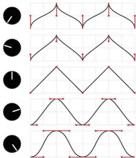
[CURVE] sets the interpolation Bézier control points from exponential to linear to logarithmic.

OUTPUTS DESCRIPTION
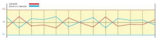
[AB AVERAGE] & [INVERTED AVERAGE] the average and inverted average of channel A & B: (A+B)/2

line
| X | CHANGE 4 | CHANGE -1 | AVERAGE | | --- | --- | --- | --- | | 0 | -2.0 | -1.5 | -1.8 | | 1 | 0.5 | 0.8 | 0.6 | | 2 | -0.5 | -1.0 | -0.7 | | 3 | 1.2 | 0.9 | 0.7 | | 4 | -1.5 | -0.8 | -0.6 | | 5 | 0.8 | 0.6 | 0.4 | | 6 | -2.5 | -1.2 | -1.0 | | 7 | 0.3 | 0.7 | 0.5 | | 8 | -0.8 | -0.5 | -0.3 | | 9 | 1.5 | 0.4 | 0.2 | | 10 | -1.2 | -0.9 | -0.6 | | 11 | 0.6 | 0.3 | 0.1 | | 12 | -0.3 | -0.7 | -0.4 | | 13 | 1.8 | 0.7 | 0.6 | | 14 | -1.8 | -1.4 | -1.1 | | 15 | 0.4 | 0.2 | 0.3 | | 16 | -0.6 | -0.3 | -0.5 | | 17 | 1.3 | 0.5 | 0.4 | | 18 | -1.6 | -1.1 | -1.3 | | 19 | 0.7 | 0.6 | 0.5 | | 20 | -0.9 | -0.6 | -0.8 | | 21 | 1.6 | 0.8 | 0.7 | | 22 | -1.4 | -1.0 | -1.2 | | 23 | 0.2 | 0.4 | 0.3 | | 24 | -0.7 | -0.5 | -0.6 | | 25+ | 0.9 | 0.7 | 0.8 |[WAVE] The "wave" CV output
[INVERTED WAVE] The "wave" inverted CV output
line
| Month | Red Line Value | Blue Line Value | |-------|----------------|-----------------| | Jan | -0.5 | 0.5 | | Feb | 0.5 | -0.5 | | Mar | -0.5 | 0.5 | | Apr | -0.5 | 0.5 | | May | 0.5 | -0.5 | | Jun | -0.5 | 0.5 | | Jul | 0.5 | -0.5 | | Aug | -0.5 | 0.5 | | Sep | 0.5 | -0.5 | | Oct | -0.5 | 0.5 | | Nov | 0.5 | -0.5 | | Dec | -0.5 | 0.5 |LEDS MONITOR
The leds on top monitor each channel voltage and gate outputs


GATE OUTPUT
There are two [GATE] output behaviour depending on the channel.
CHANNEL A - CLOCK OUTPUT
The Gate output will be output a 15ms trigger at every new cycle.
CHANNEL B - COMPARATOR OUTPUT
The Gate output will be ON when the voltage output is above it's mid range position. As an example, if no offset is applied the gate will be ON while on the positive side and OFF when on the negative side

line
| Channel | Voltage Level | | ------- | ------------- | | CHANNEL A: CLOCKED | -10 | | CHANNEL B: COMPARATOR | -5 |
BÉZIER INTERPOLATION
As described in wikipedia "Bézier curves are widely used in computer graphics to model smooth curves. As the curve is completely contained in the convex hull of its control points, the points can be graphically displayed and used to manipulate the curve intuitively"
Here we take advantage of these control points to interpolate between the 2 random points, we approach the control points in a very controlled manner: they move vertically when the control knob turned counter clockwise (up to half the difference of the 2 random points) and move horizontally when turned clockwise (up to half of the cycle period). At noon the interpolation is linear.
The graphics on the right show examples of these principles with control points in red.
Shown below are three examples of the curve shapes over time, these are 3 particular cases with control knob positioned at: fully counter clockwise, noon and fully clockwise. Also shown the inverted wave output.
CURVE INTERPOLATION

Here you can see these three examples overlapped.

CROSS PATCHING
To allow for more dynamic and unpredictable behaviour, by default the module ships with Channel A output internally routed to Channel B Frequency and Level as well as Channel B output internally routed to Channel A Frequency and Level. The attenuverters control the gain of each input.
As we all know it is almost physically impossible to completely attenuate a cv input using attenuverters, there's always some minor leakage, if this effect in not desired. It is possible to internally disabling this routings via jumpers on the back.
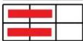
Notice the jumpers location on the back pcb and the desired position for each of the 4 jumpers on the graphic below.
Whenever a jack is inserted this internal routing is physically disabled.

CHANNEL 2 OUTPUT TO:
CHANNEL 1 OUTPUT TO:

FREQUENCY A
LEVEL A
FREQUENCY B
LEVEL B
DEFAULT STATE

SIGNAL FLOW DIAGRAM
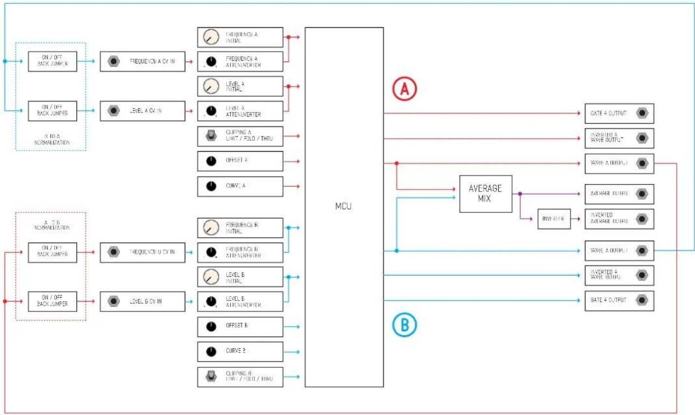
flowchart
graph TD
    A["ON / OFF BACK JUMPER"] --> B["FREQUENCY A CV IN"]
    C["ON / OFF BACK JUMPER"] --> D["LEVEL A CV IN"]
    E["H I U A NORMALIZATION"] --> B
    E --> D
    B --> F["FREQUENCY A INITIAL"]
    B --> G["FREQUENCY A ATTENUERIER"]
    D --> H["LEVEL A INITIAL"]
    D --> I["LEVEL A ATTENUERIER"]
    D --> J["CLIPING A LIMIT / FOLI / THRU"]
    D --> K["OFFSET A"]
    D --> L["CURVE A"]
    M["A 7 B NORMALIZATION"] --> N["FREQUENCY U CV IN"]
    O["ON / OFF BACK JUMPER"] --> P["LEVEL B CV IN"]
    Q["ON / OFF BACK JUMPER"] --> R["FREQUENCY B INITIAL"]
    Q --> S["FREQUENCY B ATTENUERIER"]
    Q --> T["LEVEL B INITIAL"]
    Q --> U["LEVEL B ATTENUERIER"]
    Q --> V["OFFSET B"]
    Q --> W["CURVE B"]
    Q --> X["CLIPING B TIMI / FOLI / THRU"]
    Y["MCU"] --> Z["AVERAGE MIX"]
    Z --> AA["CATE A OUTPUT"]
    Z --> AB["INVERTED A WAVE OUTPUT"]
    Z --> AC["WAVE A OUTPUT"]
    Z --> AD["AVERAGE OUTPUT"]
    Z --> AE["INVERTED AVERAGE OUTPUT"]
    Z --> AF["WAVE A OUTPUT"]
    Z --> AG["INVERTED 4 WAVE OUTPUT"]
    Z --> AH["BATE 4 OUTPUT"]
For feedback, comments or problems please contact us at: addac@addacsystem.com


Brand : ADDAC System
Model : ADDAC507
Category : Synthesizer