CSB315 - Saw Cotech - Free user manual and instructions
Find the device manual for free CSB315 Cotech in PDF.


| Product Type | Table Saw |
| Model | CSB315 |
| Brand | Cotech |
| Motor Voltage | 230 V |
| Motor Power | 2.2 kW (S6 20%) |
| No-Load Speed | 2800 rpm |
| Saw Blade Diameter | 315 mm |
| Blade Bore | 30 mm |
| Blade Thickness | 3.0 mm |
| Max Cutting Depth at 90° | 90 mm |
| Max Cutting Depth at 45° | 50 mm |
| Table Dimensions | 550 x 800 mm |
| Extension Table Size | 550 x 800 mm |
| Working Height | 810 mm |
| Net Weight | 44 kg |
| Gross Weight | 50 kg |
| Package Dimensions | 940 x 660 x 470 mm |
| Blade Tilt Range | 0° to 45° |
| Riving Knife Gap | 3 mm |
| Safety Features | Riving knife, blade cover, emergency stop, circuit breaker, push stick |
| Included Accessories | Stand, shavings tank, rip fence, push stick, blade, wrenches |
| Optional Accessories | Extension table, mitre gauge (30-8627), wheel set |
| Maintenance | Regular cleaning, oiling of moving parts, check blade sharpness and alignment |
Frequently Asked Questions - CSB315 Cotech
User questions about CSB315 Cotech
0 question about this device. Answer the ones you know or ask your own.
Ask a new question about this device
Download the instructions for your Saw in PDF format for free! Find your manual CSB315 - Cotech and take your electronic device back in hand. On this page are published all the documents necessary for the use of your device. CSB315 by Cotech.
USER MANUAL CSB315 Cotech
Read the entire instruction manual carefully and make sure that you fully understand it before you use the equipment. Keep the manual for future reference.
Viktig information:
natural_image
Exterior view of a metal robotic platform with visible wiring and control panel (no text or symbols)ART.NO. MODEL
30-8501 CSB315
Ver. 200810
Table Saw
ART. No: 30-8501 MODEL: CSB315
Please read the entire instruction manual before using and save it for future use. We apologise for any text or photo errors and any changes of technical data. If you have any questions concerning technical problems please contact our Customer Service Department (see address on reverse.)
Content
- General Safety Rules ....4
- Special Safety Regulations .... 5
- Safety Symbols 7
- Important Safety Features 8
- Unpacking and Assembly 9
5.1 Before First Use 9
5.2. The following parts should be mounted before the saw can be used .....9
5.3 Mounting the stand 9
5.4 Shavings Tank 9
5.5 Circuit breaker ....10
5.6 Saw Blade ....10
5.7 Adjusting Parallelism ....10
5.8 Mounting Rip fence ....11
- Use....11
6.1 Setting the Saw Height 11
6.2 Setting the Saw Blade's Cross Fall ....12
6.3 Using the Rip fence ....12
6.4 Using the Mitre Holder ....12
- Care 12
- Troubleshooting ....13
- Transport ....13
- Attachments/parts ....13
- List of Components ....15
- Attachments, Assembly ....17
- Protect the Environment ....19
- Specifications ....19
1. General Safety Rules
Always remove the cable plug from the socket before servicing and adjusting the product!
Warning! When using electrical tools the following safety rules should always be followed in order to avoid risk of fire, electric shock and personal injury.
1. Keep the working area clean!
Cluttered surfaces and tables invite accidents.
2. Do not use the tool in high risk environments!
Electrical machines should not be used on damp or wet surfaces or in the rain. Make sure that the lighting is good in the workplace. Provide good ventilation during dusty jobs. Never use electrical machinery/tools where they may cause fire or explosion!
3. Avoid electric shock!
Avoid physical contact with earthed objects such as water mains, radiators, hobs etc. when using electrical machinery/tools.
4. Keep children and visitors at a distance!
All children and visitors should be kept at a safe distance from electrical machinery/tools or electric cables in the workplace.
5. Keep the machinery childproof!
Keep electrical machinery/tools locked away or out of reach of children when not in use!
6. Do not push the machinery!
It will carry out the work better and more safely at the intended feed rate.
7. Use the correct tool!
Do not push a tool or any other attachment to perform an operation which it is not designed for.
8. Wear suitable attire!
No loosely fitting clothes, gloves, necklaces, rings, bracelets or other jewellery which may get stuck in the rotating parts. Skid-proof shoes are recommended. Wear a hairnet (or equivalent.) if you have long hair.
9. Wear goggles!
Always wear goggles, ordinary glasses are not suitable! Also use a dust filter or protective mask during dusty work.
10. Use an extractor!
Use an extractor to remove and collect dust and shavings, if the machine is designed for it; make sure the machine is used correctly and emptied when needed.
Warning! Dust and shavings from some wood types and wood products can damage your health even following a short period of exposure.
11. Do not damage the electric cable!
Never carry the machine by its electric cable. Do not pull the cable but instead pull out the plug when cutting off power. Make sure the cable does not come into contact with heat, oil or sharp edges.
12. Secure work material properly!
Use clamps or vices where possible, allowing you to manage the tool with both hands. It is safer than securing work material with one hand.
13. Do not stretch yourself too far!
Make sure that you adopt a secure and balanced posture the whole time.
14. Keep the tools in trim!
Make sure they are clean and that the edges are kept sharp for optimal effect and greater results. Follow the manual's recommendations for lubricating and changing parts. Check the electrical cable regularly; if damaged it should be replaced by qualified service technicians. Inspect all extension cables regularly so that they are not damaged. Make sure that the machine's/tool's handles and levers are dry, clean and free from oil, grease etc.
15. Turning off the power!
Pull out the plug and press emergency stop (if one exists) before service and replacement of attachments such as plane irons, drills, bits, emery cloth or knives.
16. Remove all adjusting keys, wrenches and service tools!
Make a habit of checking that all keys and service tools are removed from the machine before turning on the power.
17. Avoid accidental starts!
Do not carry a tool with one finger on the power button if the cable is in the socket. Make sure that the power button is set to OFF when plugging in.
18. Use correct extension cables!
If you use extension cables outdoors, only use ones intended for outdoor use.
Use extension cables with sufficient conductor lead area and unwind the entire cable!
19. Use common sense and be careful!
Think before carrying out a task so that you are able to carry it carry correctly! Never use the machine/tool when you are tired, on medication etc.
20. Check that all parts are undamaged!
Check before starting up the tool: that all protective parts and other parts are undamaged and fulfil their function; that rotating parts rotate freely and are correctly aligned; that no moving parts can get stuck; that no defect or other factors have emerged that may hamper the work's performance. A cover or other part that is damaged should be repaired per part or be replaced. Damaged electrical cables and power switches should always be replaced by professionals. Never use the tool if you can not turn it on or off safely.
21. Use recommended parts!
Using non-recommended parts can cause accidents or risk personal injury.
22. Repaired only by qualified technicians!
The tool corresponds to current safety standards. Repairs on the tool should always be carried out by professionals using original reserve parts, otherwise the tool may cause accidents or risk for personal injury.
23. Electrical tools should be connected to the mains via a circuit-breaker to ensure personal safety!
The product may not be changed or used for tasks it is not designed for! Regularly check that all screws and bolts are properly tightened!
2. Special safety regulations for circular saws, table saws and compound mitre saws
Warning! Pull out the electrical cable's plug out of its socket before servicing or changing blade.
Attention! Before starting up the saw check that all parts are working satisfactorily and that safety regulations protect as intended!
-
Warning! Only use cutting blades. Make sure that the Tungsten Carbide blades have negative toothing. Do not use blades with deep spaces between the teeth because they can bend and come into contact med the blade cover. A damaged saw blade should be replaced immediately!
-
Do not use the saw until it is completely assembled and mounted correctly according to this manual. Check the motor's and the blade's direction of rotation (see rotation arrow on the blade cover). Check that the saw blade does not touch the rotation table in any setting.
-
If you do not understand how the saw should be handled you should ask a qualified person for advice.
-
Warning! Keep your hands away from the blades. Saw only small pieces. Use pusher!
-
Check that the blade is well centred and sharp and can run free without vibrating.
-
Let the motor come up to speed before sawing.
-
Keep the motor's ventilation holes clean and free from shavings.
-
Always make sure that all the clamps are tight before you saw, even if the table is set at a fixed angle.
-
Make sure that the blade and collars are clean and that the spider nut is tight, only use blade collars that go with your saw.
-
The riving knife should have a radius corresponding to the saw blade's diameter.
-
Only use saw blades with a diameter, velocity class and other requirements given in the machine's technical specifications.
-
Always have extra support when sawing long pieces.
-
Always check before sawing that the blades are not cracked or damaged. Immediately replace a damaged blade!
-
Do not use the saw if any component is missing, damaged or faulty, pull out plug to the saw if it begins to sound strange or vibrate. Allow qualified service technicians to replace missing components or which do not work before using the saw again.
-
Never saw if protective covers are not correctly mounted and work with any problems.
-
Never stretch yourself around or behind the blade when it is rotating. Stand securely to keep your balance the whole time.
-
Check that the blade can rotate freely (especially after transport and/or blade change) before you plug in and start up the saw.
-
Do not use high speed steel blades (HSS) if the machine came with Tungsten Carbide blades.
-
Do not remove fastened or cut pieces before the blade has stopped.
-
Never saw into iron-based metals or in bricks or mortar.
-
Never use the saw in proximity to easily inflammable fluids or gases.
-
Never clean the saw's plastic parts with solvents. Solvents can dissolve the plastic or damage the material in another way. Only clean with a soft, damp cloth.
-
Pull out the plug and clean the saw before leaving it. Make sure that work surfaces are tidy before you finish the job.
-
Save this manual. Read it often and use it to instruct others. Make sure that everyone using the saw reads these instructions.
-
Do not expose the saw to rain and do not use the machinery in damp areas.
-
Keep the working area well lit.
-
Wear suitable working clothes as loosely fitting clothes or jewellery may get stuck in the rotating parts.
-
Users should be at least 18 years old; users who are 16 years old should be accompanied by an instructor when using the saw. Keep children away from the saw when it is connected to the mains.
-
Keep your working area tidy; do not allow cuttings or other waste to lie around unnecessarily. Make sure that overflow can be removed from the saw blade otherwise they can fly out of the saw blade.
-
Do not distract people working with the saw.
-
Do not try to stop the blade by pressing something against the side of the blade when you have turned off the power-supply to the saw.
- Never use saw blades which do not comply with the specifications in this manual.
- It is important to always check that all covers on the saw blade are functioning well.
- Never lock the protective hood in the open position and never disassemble the machine's cover and do not alter their function. Never use a damaged or faulty safety appliance. Replace it immediately!
- Make sure you keep hands in a safe position, so that they do not end up in the saw blade if you lose balance. Never saw pieces that are too small to be held in a safe manner.
- To avoid tipping the machine, use a table; roll support etc if the work material is long.
- Clamp tightly round work pieces with proper appliances, to prevent rotation.
- There must never be nails or other foreign objects in the piece you are going to saw.
- Always stand to the side of the saw blade when the machine is in use, to avoid being struck by the blade if it should break.
- Always press the workpiece against the table and the guide fence when sawing to prevent it from turning or moving during sawing.
- Never saw several objects at the same time.
- Never attempt to remove shavings, splinters or wood that has gotten stuck when the saw blade is rotating. If you adjust the machine or remove pieces that have gotten stuck, always switch off the machine first and pull out the plug from the mains.
- If you change, adjust or clean the machine or measure the object, always switch off the machine first and pull out the plug from the mains.
- Switch off the motor and pull out the plug from the mains when you leave your work area.
- Electrical installation, repairs or maintenance to the machine should always be carried out by professionals.
- All covers and safety appliances should be remounted immediately after repairs or maintenance.
- It is important to follow the manufacturer's safety, use and maintenance instructions, as well as following the dimension specifications provided in the “technical data”.
- It is important to follow the Health and Safety at Work regulations as well as other general safety regulations.
- The saw should always be connected to sockets with 230V fitted with at least a 10 A fuse.
- Damaged safety appliances and parts should be replaced or repaired by professionals at an authorized service centre.
- This machine corresponds to all relevant safety regulations. The machine may only be repaired by professionals at authorized service centres with original parts. If you do not follow this rule it could lead to accidents and expose the user to danger.
- Do not use the saw blades that are thicker or thinner than the riving knife (applies to circular saws).
- Always use a riving knife when cutting.
- Check that the riving knife is adjusted so that the distance between the saw blade's teeth and the riving knife is 3 mm or less.
3. Safety Symbols

Please read the entire instruction manual before using and save it for future use.

Warning! Always use goggles or visors, a respirator and hearing protection.
4. Important Security Features
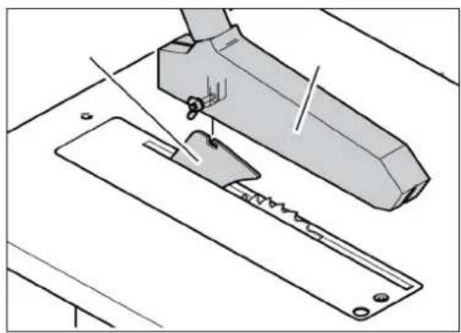
- The riving knife should be mounted/adjusted correctly to prevent the stock from kicking back when cutting. Fig 1.
- The blade cover should be mounted/adjusted correctly and not faulty to prevent accidental contact with the saw blade.
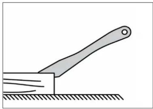
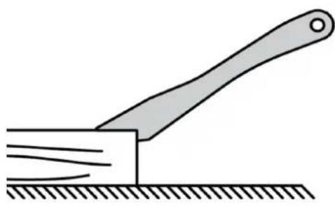
- The pusher should always be used if the piece to be cut is smaller than 120 mm. Make a new pusher when the current one is damaged. Fig 2.
natural_image
Technical line drawing of a mechanical assembly with a tool and cutting tool (no text or symbols)Fig 1.
natural_image
Simple line drawing of a tool applying material to a block on a surface (no text or symbols)Fig 2.
To think about:
- Working with wood can be hazardous if carried out incorrectly!
- If you use the saw sensibly and carefully you will greatly reduce the risk of personal injury.
- Safety equipment in the form of protection, pushers, clamps, goggles, dust filters and hearing protection cannot compensate for poor judgement, carelessness or lack of attention!
- Remember: you are responsible for your own safety. The saw has been constructed for certain jobs. We strongly recommend that you do not alter the saw or use it for anything other than what it was designed for.
- DO NOT USE THE SAW if you are not sure whether it can be used or ought to be used in the way you intended!
5. Unpacking and Assembly
For assembly you will need the following tools:
- Screwdriver (Philips)
- Spanners: 7 mm, 8 mm, 17 mm, 22 mm and two 10 mm
- You will also need a pair of gloves, necessary when handling the saw blade.
Your new saw arrives partly assembled in the package. Carefully remove the saw and all loose parts from the package.
5.1 Before using the table circular saw for the first time
- Assemble the circular saw according to these instructions. The machine only meets the safety if it is assembled according to the instructions.
- Read all the instructions before using the table saw.
- Save the instructions for future reference.
5.2 The following parts should be assembled before the saw is used
- Stand
- Circuit breaker
- Shavings Tank
- Saw blade and fence
- Stand. (The four legs are foldable, and not extended on delivery).
5.3 Assembling the stand
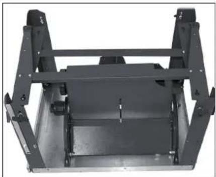
Extend the legs and tighten the wing nuts. Assemble the cross-strut and tighten the chrome locking bolts. Fig 3, 4 and 5.
natural_image
Metal frame structure with support beams and internal components (no visible text or symbols)
natural_image
Mechanical device with a hand adjusting its frame, showing a small object inside and an upward arrow indicating motion (no text or symbols visible)
Fig 3, 4 and 5.
ATTENTION! The bolts for the stand should be put in the notches in order to fasten the wing nuts.
5.4 Shavings Tank
Assemble the tank with three self-threading screws (ST 3.5x13) and two screws (M4x8) as shown in Fig 6.

natural_image
Close-up of a hand using a tool to adjust or install a mechanical component (no visible text or symbols)Fig 6.

natural_image
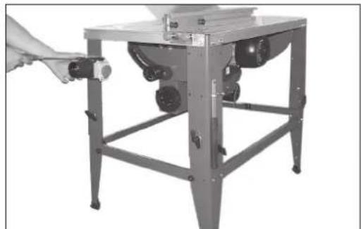
Mechanical assembly with a hand operating a tool on a metal frame (no visible text or symbols)Fig 7.
5.5 Circuit breaker
Attach the circuit breaker to the front with two M4x60 screws and locking bolts. Attach the cable with bundling tape so it does not come loose.
The circuit breaker has an emergency stop function. It is meant for quickly stopping the machine when necessary, in case of danger or if the machine starts vibrating.
- Start the machine by lifting the red emergency stop button cover, and by pressing the green button marked "1", for approximately 1 second.
- Turn off the machine by pressing the emergency stop button.
- You may use the emergency stop button whenever you need to stop the machine. Emergency stop is activated until you want to start the machine again, as shown in Fig 7.
5.6 Saw blade
ATTENTION! Always use gloves when handling the saw blade.
- Lift up the motor completely.
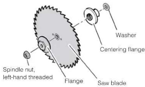
- Assemble the parts in this order. Fig 8.
- Mount the riving knife, centre it in line with the saw blade and tighten the bolts. Fig 9.

natural_image
Close-up of hands using a wrench to adjust a blade with a saw blade (no visible text or symbols)Fig 9.

Fig 10.
ATTENTION! The distance between the riving knife and saw blade must be 3 mm, tighten the screws when the distance is set. Fig 10.
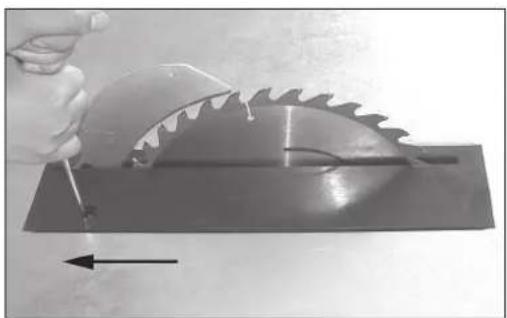
- Place the table-insert in the groove round the saw blade and pull it back, as shown in Fig 11.
natural_image
Close-up of a hand using a tool to cut a saw blade on a metal cutting board (no text or symbols visible)Fig 11.
- Mount the blade cover on the riving knife with M5x50 screws with locking bolts.
- Connect the extractor hose to the shavings tank.
ATTENTION! Use the adjusting wheel to lift the saw blade to its upper level, and check the saw blade is completely parallel with the table and that the saw blade does not make contact with any part of the table at 45^ or 90^ sawing.
5.7 Adjust Parallelism
- Loosen the six locking bolts holding tight the attachment brackets to the motor under the saw table, one revolution.
- Turn the motor unit until it is parallel with/or at the right angle to the rulers. Fig 12.

5.8 Mounting the Rip Fence
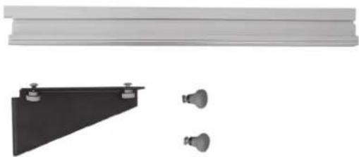
Parts (Fig 13)
Name Number
Extension 1
Stop 1
Nuts 2
Tightening bolt M6 x 20 2
Knobs 2
Tightening bolt M6 x 20 2
natural_image
Pure architectural or mechanical components without any text, numbers, or symbolsFig 13.
- In order to be able to use the circular saw for longitudinal cutting the rip fence must be attached to the stop and to the ruler at the front of the table.
- Push the screw heads into the cutting ruler
- When the two nuts have been loosened, the rip fence can be removed and changed to:
• High fence: For rough pieces. Fig 14.
- Low fence: For thin pieces. When the saw blade is bevelled. Fig 15.
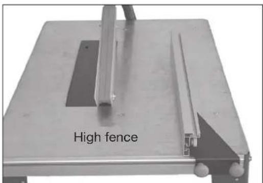
Fig 14.

Fig 15.
6. Use
- The table circular saw is meant specifically for cross-cutting and cutting solid wood and similar sheet and block materials such as masonry blocks, wood fibre blocks and plywood.
- When sawing round pieces they must be fastened securely so that they do not rotate.
- By intended use it is meant that the user follows the instructions given by the manufacturer for operation, care and repairs and abides by all safety regulations.
Any use beyond what has been given is not deemed intended use. The manufacturer does not take responsibility for unintended use, but such use is the responsibility of the user.
6.1 Setting the Cutting Height
The cutting height needs to be adjusted to the workpiece's thickness: The blade cover's frontal section should rest against the workpiece.
Adjust the cutting height with the hand wheel on the motor box. Fig 16.
ATTENTION! To compensate for the gap in the height adjustment: begin by winding down the saw blade to a level lower than the intended cutting height; then wind up to the correct setting.
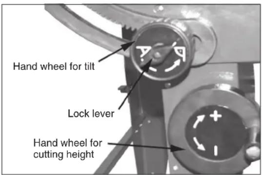
Fig 16.
6.2 Setting the Saw Blade's Bevel Angle
The saw blade can be tilted between 0^ and 45^ .
- Loosen the locking lever.
- Adjust the tilt with the hand wheel.
- Tighten the lock lever to make sure the setting has been changed.
6.3 Using the Rip Fence
ATTENTION! When cutting, the fence should be used. Always use the pusher if the distance between the saw blade and holder is less than 120 mm.
- The rip fence is mounted from above, on the front of the saw, and locked using the locking lever.
- Set the correct cutting height. The front of the blade cover should rest on the workpiece.
- Set the eventual blade tilt and lock setting with the locking lever.
- Start the motor.
- Saw the piece in one continual operation.
- Turn off the machine and press "Emergency Stop" when sawing is complete.
6.4 Using the mitre gauge 30-8627 (optional extra) (not included)
- Attach the mitre gauge to the slide.
- Set correct angle and lock setting; when mitre sawing the gauge can be locked between 0° and 45°.
- Set the correct cutting height
- Set the eventual blade tilt and lock setting with the locking lever.
- Start the motor.
- Saw the piece in one continual operation.
- Turn off the machine and press "Emergency Stop" when sawing is complete.
7. Care
Before you start
- Check visually that the distance between the saw blade and the riving knife is 3 mm.
- Check visually that cables and contacts are intact; allow a qualified electrician to replace any possible damaged parts.
Every month (with daily use)
- Remove dust and shavings with a brush or vacuum cleaner.
- Apply a thin coat of oil on: threaded bar and controls, on the height adjuster of the saw blade.
- Remove the plug first from the wall socket.
To ensure good functionality care should also include the following
- Regular cleaning and oiling in of all moving parts;
- Cleaning of dirty motor cooling flanges to ensure good cooling;
- Make sure that the blade is free of rust and resin;
- Clean the saw and table when coated with resin;
- Resharpening or replacing of the blade, which after extended use has blunt teeth.
8. Troubleshooting
| Fault Cause Solution | ||
| The saw does not start. Faulty cable. Replace cable. | ||
| The motor is too weak, and heats up too quickly. | Poor extension cable, too long, small area. | Replace cable, do not overload the saw. |
| Smells burnt when starting. | Assembly fault. Assemble correctly. | |
| Defective machine. Replace the saw with a new one. | ||
ATTENTION
- A qualified electrician must be employed for permanent connections to the mains.
- Always use personal protective equipment: hearing protection, protective goggles and protective masks when necessary.
9. Transport
- Lower the saw blade completely.
- Adjust the blade tilt to 25^ and pull in the legs on the upper level.
- Disassemble the extension table, ruler and holder.
- Use the original packing for longer transport.
10. Attachments
Wheel attachment: easier for moving the saw
Description: Number:
Wheel with assembly information 2
Handle 2
Bolts M6x16 4
Flat washer 6 mm 4
Locking bolts M6 4
Bolts M6x16 2
Flat washer 6 mm 2
Lock nuts M6 6
Extension table: place on side or back
Description: Number:
Extension table 1
Support (long) 2
Support (short) 2
Adjusting screw M6 2
Carriage bolt M6x12 2
Moveable holder with slide (accessory, not included) Simple handling of long pieces
Description: Number
Slide with assembly information 1
Ruler 1
Mitre gauge 1
Ruler mount 2
Adjusting screw M6 1
Bolts M6x16 1
Flat washer 6 mm 1
Lock nuts M6 1
Flat washer 6 mm 1
Bolts M6x16 4
Flat washer 6 mm 4

natural_image
Close-up of mechanical components including two wheels, four screws, and a metal bracket (no visible text or symbols)
natural_image
Stack of three black plastic strips on a white background, no text or symbols visible
natural_image
Two technical diagrams: one showing a mechanical component with four circular features, the other displaying a curved metal part with three holes and two rectangular plates (no text or symbols present)
natural_image
Black-and-white photo of a manual labor machine with a flat blade and metal frame (no visible text or symbols)
natural_image
Industrial machine with metal frame and handle, no visible text or symbols11. Parts list

-
-
-
-
-
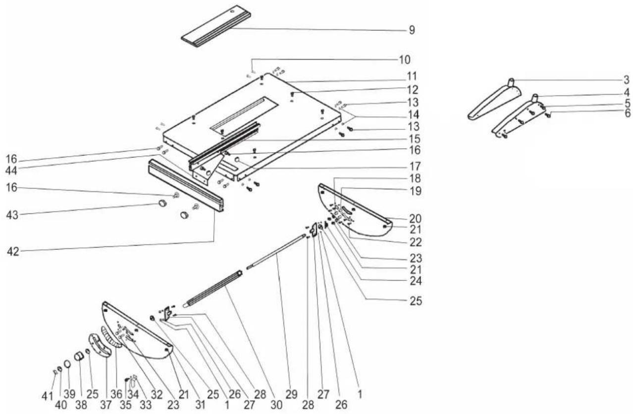
Blade cover, upper right
-
Blade cover, upper left
-
Countersunk screw, self-tapping ST 3.5x25
-
Countersunk screw M5x30
-
-
-
-
-
Table insert
-
Bolt M6x12
-
Table
-
Countersunk screw M6x16
-
Bolt M6x16
-
Copper sleeve
-
Rip fence
-
Carriage bolts M6x16
-
Nuts
-
Copper sleeve
-
Steel tube
-
Attachment bracket rear
-
Lock nuts M6
-
Countersunk screw, self-tapping ST 3.5x13
-
Flat washer 6 mm
-
Lock washer
-
Lock washer
-
Flat washer 5 mm
-
Shaft support
-
Phillips screw M5x12
-
Adjustment pipe
-
Adjustment shaft, linear rack gearing
-
Bracket attachment frontal
-
Bolt M5x12
-
Index marking
-
Lock washer
-
Phillips screw, self-tapping ST 3.5x9.5
-
Angle marking
-
Plate
-
Hand wheel, for tilting of saw blade
-
Angle indicator
-
Adjusting washer
-
Locking lever
-
Ruler for rip fence
-
Adjusting knob
-
Rip fence stop

-
Saw blade
-
Blade flange, centring
-
Adjustment washer
-
Bolt M6x8
-
Allen screw M6x8
-
Flat washer 6 mm
-
Crank
-
Height indicator
-
Crank screw
-
Bolt M6x16
-
Flat washer 6 mm
-
Nut M6
-
Hand wheel, height setting
-
Flat washer 10 mm
-
Support
-
Spacer
-
Adjustment shaft, linear rack gearing
-
Spacer
-
Nut adjustment shaft
-
Flat washer 6 mm
-
Track pad
-
Spring washer
-
Motor box
-
Motor
-
Phillips screw M4x13
-
Phillips screw, self-tapping 3.5x13
-
Shavings tank
-
Motor attachment
-
Rivet
-
(Missing)
-
Adjustment shaft bracket
-
Riving knife bracket
-
Carriage bolts M10x25
-
Track pad
-
Strut
-
The riving knife
-
"U" plate
-
Support adjustment shaft
-
Lock nut M10
-
Blade flange
-
Nut, left-hand threaded
-
Motor box, bottom plate
-
Motor box, top plate

- Locking nut M4
- Hose
- Circuit breaker bracket
- Circuit breaker
- Phillips screw M4x60
- Flat washer 8 mm
- Wing nuts
- Handle
-
Rubber handle
-
Machine foot, rubber
- Strut, short
- Carriage bolts M4x60
- Leg, upper (right)
- Leg, lower (right)
- Strut, long
- Carriage bolts M8x16
- Leg, upper (left)
- Leg, lower (left)
12. Attachments, assembly
Assembly of extension table
Rear extension
- Loosen the four bolts on the back of the table frame, mount the extension table (200) from above; make sure that the four grooves on the table's edge come before for each bolt.
- Mount the M6x16 carriage bolts (203) from the outside in the hole on the cross support.
- Attach the locking wheel (204) on the bolt but do not tighten it yet.
- Mount the long support (202) on the bolt and tighten the locking wheel.
- Mount the M6x16 carriage bolts (203) from the inside, in the hole of the table (200) and the hole in the support (202).
- Screw on the locking wheel (204) on the bolt (203) and tighten.
ATTENTION! It is important that the extension table is not higher than the main table, otherwise the piece can get stuck or kick back.

Extension on the right-hand side
- Loosen the four bolts on the right-hand side of the table frame, mount the extension table (200) from above; make sure that the four grooves on the table's edge come before for each bolt.
- Mount the M6x16 carriage bolts (203) from the outside in the hole on the cross support.
- Attach the locking wheel (204) on the bolt but do not tighten it yet.
- Mount the long support (202) on the bolt and tighten the locking wheel.
- Mount the M6x16 carriage bolts (203) from the inside, in the hole of the table (200) and the hole in the support (202).
- Screw on the locking wheel (204) on the bolt (203) and tighten.
- Push two carriage bolts (206) in the notch on the extendable ruler (205), mount the M6 flat washer and locking wheel.
- Attach the extendable ruler (205) on the front of the table (200).
- Adjust the extendable ruler so that it is parallel with the existing ruler. Tighten the locking wheels (204)
Number Description Number
200 Extension table 1
201 Support, short 2
202 Support, long 2
203 Carriage bolts M6x16 4
204 Locking wheel M6 6
205 Extension ruler 1
206 Carriage bolts M6x20 2
207 Flat washer M6 2

Mounting of slide and the mitre gauge support (accessory, not included)
- Place the mitre gauge support (4) on the slide (3), screw in the chrome screw in the threaded hole in the slide.
- Use 4 M6x16 bolts (9) to mount the ruler support (7) on two of the machine's legs, but do not tighten the screws yet.
- Place the ruler (1) on the ruler support (7), and attach with M6 screws (8), but do not tighten the screws yet.
- Remove the stop-screw (6), press the slide (3) on the ruler (1), screw back the locking screw and tighten.
- Adjust the screws (9) and (8) to see that the ruler is parallel with the saw table and at the same height. Tighten the screws.
Test the saw to check the setting!
13. Protect the environment
Follow local ordinances when disposing of this product. If you are unsure about how to dispose of this product contact your municipality.
14. Specifications
Motor: 230 V, 2.2 kW (S6 20%)
Max saw depth at 45^/90^ : 50/90 mm
Size, table: 550 x 800 mm
Size, extension table: 550 x 800 mm
Working height: 810 mm
Saw blade: 315 mm x 3.0 mm x 30 mm
Speed: 2800 rpm
Weight, net/gross: 44/50 kg
Package size: 940 x 660 x 470 mm
Bordscirkelsåg
natural_image
Technical line drawing of a mechanical assembly with a tool and component (no text or symbols)Bild 1.

natural_image
Simple line drawing of a tool applying material to a block, with no text or symbols present.Bild 2.
Tänk på detta
natural_image
Mechanical assembly frame with metal components and mounting brackets (no visible text or symbols)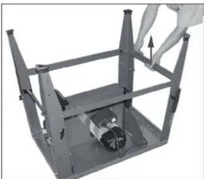
natural_image
Mechanical assembly with a hand pressing a component, no visible text or symbols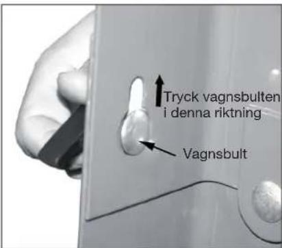
natural_image
Close-up of a hand using a tool to adjust or install a mechanical component, no visible text or symbolsBild 6.

natural_image
Industrial machine with metal frame and mounted components, no visible text or symbolsBild 7.
5.5 Strömbrytare
natural_image
Close-up of hands using a tool to cut a saw blade (no text or symbols visible)Bild 9.

Bild 10.
natural_image
Hand using a tool to cut a saw blade on a cutting board (no text or symbols visible)Bild 11.
natural_image
Technical line drawing of a mechanical assembly with a close-up inset showing a component (no text or symbols)natural_image
Pure electrical circuit lines without any symbolsBild 13.
natural_image
Close-up of mechanical pulley and bracket components (no text or symbols visible)
natural_image
Exterior view of a modern office building (no signage)
natural_image
Exterior view of a metal enclosure with multiple switches and a protractor (no text or symbols visible)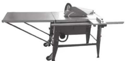
natural_image
Black-and-white photo of a flat-screen office chair with a circular vent and mechanical legs (no text or symbols visible)
natural_image
Industrial machine with metal frame and wooden base (no visible text or symbols)11. Komponentlista
natural_image
Technical line drawing of a sewing machine tool with a spring and base plate (no text or symbols)Bilde 1.
natural_image
Simple line drawing of a tool applying material to a surface (no text or symbols)Bilde 2.
Husk:
5.3 Montere stativet
natural_image
Metal frame structure with support beams and internal components (no visible text or symbols)
natural_image
Mechanical assembly with a hand adjusting a component, no visible text or symbols
natural_image
Close-up of a hand using a tool to adjust or install a mechanical component (no visible text or symbols)Bilde 6.
natural_image
Mechanical device with metal frame and attached cylindrical components, no visible text or symbolsBilde 7.
5.5 Strømbryter
natural_image
Close-up of hands using a saw blade to cut a mechanical component (no visible text or symbols)Bilde 9.

Bilde 10.
natural_image
Close-up of a hand using a saw blade to cut a saw blade on a cutting board, with an arrow indicating direction (no text or symbols visible)Bilde 11.
natural_image
Close-up of mechanical components including wheels, screws, and a metal bracket (no text or symbols visible)
natural_image
Exterior view of a modern office building (no signage)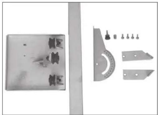
natural_image
Exterior view of a wall-mounted electrical switch and its corresponding measurement tool (no text or symbols visible)
natural_image
Black-and-white photo of a flat-screen office chair with a circular cutter and mechanical components (no visible text or symbols)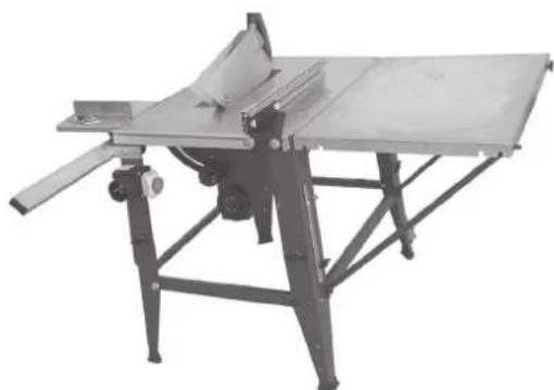
natural_image
Industrial machine with metal frame and handle, no visible text or symbols11. Komponentliste

1.-
2.-
- Sageklinge
- Klingeflens, sentrering
- Justeringsskive
- Sekskantbolt, M6 x 8
- Inseksskrue M6x8
- Planskive, 6 mm
- Sveiv for ratt
- Høydeindikator
- Skrue for sveiv
- Sekskantbolt, M6 x 16
- Planskive, 6 mm
- Mutter, M6
- Håndratt for høydeinnstilling
- Planskive, 10 mm
- Støtte
- Distansering
- Justeringsaksel
- Distansering
- Mutter for justeringsaksel
- Planskive, 6 mm
- Styreplate
-
Fjærskive
-
Motorboks
- Motor
- Stjerneskrue M4 x 13
- Stjerneskrue, selvgjengende ST 3,5 x 13
- Sponstuss
- Motorfeste
- Nagle
(74. Eksisterer ikke) - Feste for justeringsaksel
- Feste for klyvekniv
- Bolt M10 x 25
- Styreplate
- Stag
- Klyvekniv
- "U" plate
- Feste for justeringsaksel
- Låsemutter M10
- Klingeflens
- Mutter, venstregjenget
- Deksel for motorboks, nedre
- Deksel for motorboks, øvre

natural_image
Technical illustration of a mechanical tool interacting with a saw blade and base plate (no text or symbols)Kuva 1.

natural_image
Simple line drawing of a tool applying material to a block, with no text or symbols present.Kuva 2.
Huom.:
natural_image
Metal frame structure with support beams and internal components (no text or symbols visible)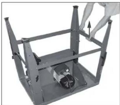
natural_image
Mechanical device with a hand operating the frame, showing a small vehicle inside and an upward arrow indicating motion (no text or symbols visible)
natural_image
Close-up of a hand using a tool to adjust or install a mechanical component (no visible text or symbols)Kuva 6.

natural_image
Industrial machine with metal frame and mechanical components, no visible text or symbolsKuva 7.
5.5 Virtakytkin
natural_image
Close-up of hands using a wrench to cut a saw blade (no text or symbols visible)Kuva 9.

natural_image
Close-up of a hand operating a gear cutting machine with a 3mm dimension label (no other text or symbols visible)Kuva 10.
natural_image
Close-up of a hand using a tool to cut a saw blade on a metal cutting board (no text or symbols visible)Kuva 11.
natural_image
Pure architectural or mechanical components without any text, numbers, or symbolsKuva 13.
natural_image
Close-up of mechanical components including wheels, screws, and a bracket (no visible text or symbols)
natural_image
Stacked rectangular panels and three parallel black strips with small protrusions, no text or symbols visible
natural_image
Two technical diagrams showing a metal bracket with four cutouts and a scale with a curved arrow (no text or symbols present)
natural_image
Black-and-white photo of a flat-screen office chair with a circular head cover and mechanical legs (no visible text or symbols)
natural_image
Mechanical machine with metal frame and handle, no visible text or symbols11. Osaluettelo

Declaration of Conformity
CE
Hereby, Clas Ohlson AB, declares that the machinery:
Table Saw Cotech
ART. NO. 30-8501 MODEL: CSB315
Complies with the provisions of the following diectives:
98/37/EC MACHINERY
2006/95/EC LOW VOLTAGE EQUIPMENT
89/336/EEC EMC
Complies with the provisions of the following harmonized standards:
EN61029-1:2000
EN55014-1:2000+A1
EN55014-2:1997+A1
EN61000-3-3:1995+A1
EN61000-3-2:2000
Insjön, Sweden, October 2008

KLAS BALKOW
President
Clas Ohlson, 793 85 Insjön, Sweden
CO TECH®
SVERIGE
KUNDTJÄNST Tel: 0247/445 00
Fax: 0247/445 09
E-post: kundtjanst@clasohlson.se
INTERNET www.clasohlson.se
BREV Clas Ohlson AB, 793 85
INSJÖN
NORGE
KUNDESENTER Tlf.: 23 21 40 00
Faks: 23 21 40 80
E-post: kundesenter@clasohlson.no
INTERNETT www.clasohlson.no
POST
Clas Ohlson AS, Postboks 485 Sentrum, 0105 OSLO
SUOMI
ASIAKASPALVELU Puh: 020 111 2222
Faksi: 020 111 2221
For consumer contact, please visit www.clasohlson.co.uk and click on customer service.
INTERNET www.clasohlson.co.uk

- Table Saw
- Content
- General Safety Rules
- Keep the working area clean!
- Do not use the tool in high risk environments!
- Avoid electric shock!
- Keep children and visitors at a distance!
- Keep the machinery childproof!
- Do not push the machinery!
- Use the correct tool!
- Wear suitable attire!
- Wear goggles!
- Use an extractor!
- Do not damage the electric cable!
- Secure work material properly!
- Do not stretch yourself too far!
- Keep the tools in trim!
- Turning off the power!
- Remove all adjusting keys, wrenches and service tools!
- Avoid accidental starts!
- Use correct extension cables!
- Use common sense and be careful!
- Check that all parts are undamaged!
- Use recommended parts!
- Repaired only by qualified technicians!
- Electrical tools should be connected to the mains via a circuit-breaker to ensure personal safety!
- Special safety regulations for circular saws, table saws and compound mitre saws
- Safety Symbols
- Important Security Features
- To think about:
- Unpacking and Assembly
- Before using the table circular saw for the first time
- The following parts should be assembled before the saw is used
- Assembling the stand
- Shavings Tank
- Circuit breaker
- Saw blade
- Adjust Parallelism
- Mounting the Rip Fence
- Use
- Setting the Cutting Height
- Setting the Saw Blade's Bevel Angle
- Using the Rip Fence
- Using the mitre gauge 30-8627 (optional extra) (not included)
- Care
- Before you start
- Every month (with daily use)
- To ensure good functionality care should also include the following
- Troubleshooting
- ATTENTION
- Transport
- Attachments
- Wheel attachment: easier for moving the saw
- Extension table: place on side or back
- Moveable holder with slide (accessory, not included) Simple handling of long pieces
- Parts list
- Attachments, assembly
- Assembly of extension table
- Rear extension
- Extension on the right-hand side
- Number Description Number
- Mounting of slide and the mitre gauge support (accessory, not included)
- Protect the environment
- Specifications
- Bordscirkelsåg
- Tänk på detta
- Strömbrytare
- Komponentlista
- Husk:
- Montere stativet
- Strømbryter
- Komponentliste
- Huom.:
- Virtakytkin
- Osaluettelo
- Declaration of Conformity
- CE
- Table Saw Cotech
- CO TECH®
- SVERIGE
- NORGE
- SUOMI
Brand : Cotech
Model : CSB315
Category : Saw