
650 - Beer dispenser Perlick - Free user manual and instructions
Find the device manual for free 650 Perlick in PDF.


| Brand | Perlick |
| Model | 650 |
| Product Type | Forward Sealing Beer Faucet |
| Category | Beer Dispenser |
| Patent | U.S. Patent #8066257 |
| Design | Ball and floating O-ring design eliminates valve shaft |
| Material | Chrome or Tarnish-Free finish options |
| Compatibility | Fits all standard North American shanks |
| Flow Control | Available on model 650SS Flow Control |
| Handle Options | Standard Handle (5A) or Push Back Creamer (5B) |
| Internal Parts | Fewer parts, no valve shaft, polished interior for smooth flow |
| Cleaning Method | Clean in place or disassemble; soak in cleaning solution, brush, rinse |
| Maintenance | Regular cleaning recommended when beer system is cleaned |
| Spare Parts | Front Seat, O-rings, Bearing Cup, Handle Lever, Bonnet, Coupling Gasket |
| Flow Control Spare Parts | Compensator, Seal Kit, Lever & Seal Kit |
| Troubleshooting | Common issues and solutions for drips, leaks, flow, and removal |
| Manufacturer | Perlick Corporation |
| Address | 8300 W. Good Hope Rd., Milwaukee, WI 53223 |
| Contact | 800.558.5592 |
| Website | perlick.com |
| Form Number | 67952 Rev. 06.05.14 |
Frequently Asked Questions - 650 Perlick
User questions about 650 Perlick
0 question about this device. Answer the ones you know or ask your own.
Ask a new question about this device
Download the instructions for your Beer dispenser in PDF format for free! Find your manual 650 - Perlick and take your electronic device back in hand. On this page are published all the documents necessary for the use of your device. 650 by Perlick.
USER MANUAL 650 Perlick
FORWARD SEALING BEER FAUCETS
U.S. PATENT #8066257

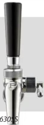
Perlick's Forward Sealing Beer Faucets are unique in both appearance and function. The revolutionary ball and floating O-ring design eliminates the need for a valve shaft. Beer is not exposed to air so the handle lever doesn't stick, and there is no build up of mold and bacteria in the faucet body. The polished interior produces a smooth flow with less foaming, ensuring a perfect pour each and every time. Fewer internal parts means better reliability and fewer service calls. This faucet will fit all standard North American shanks.
natural_image
Close-up of a metallic mechanical lever with black handle and threaded shaft (no visible text or symbols)650SS Flow Control630
Cleaning Instructions
Before using your new Perlick faucet, clean the faucet as you would for regular cleaning (see cleaning instructions below.) This will ensure that the faucet is clear of any materials that may be present from the manufacturing process.
We recommend that the faucet be cleaned when the beer system is cleaned. Regular cleaning of the faucet is extremely important. The faucet can be cleaned "in place" by simply pumping your cleaning solution through the beer system with the beer faucet in the opened position (handle forward). There is no need to remove or disassemble the faucet! By leaving the faucet installed, the cleaning solution will thoroughly clean all internal parts including the floating O-ring and its groove.
If your specific cleaning procedure requires removing the faucet from the dispensing head, soak the faucets in cleaning solution for 10-15 minutes. Use a faucet brush inside the spout, then brush out from the back of the faucet (there is no need to remove the handle assembly.) Rinse with clean water and install back on the dispensing head.
Troubleshooting
| Symptom Possible Cause (see back for Parts diagram) Possible Solution | ||
| Faucet drips or leaks from the spout | • Front Seat (7) is damaged or worn• Handle Lever (5A or 5B) is damaged• Bearing Cup (4) is not installed properly• Bonnet is loose | • Replace Front Seat• Replace Handle Lever• Reinstall Bearing Cup• Tighten Bonnet |
| Faucet leaks from flow control lever | • Worn or damaged seal• Loose cap | • Replace seals• Tighten cap |
| Faucet leaks from bonnet • O-ring (6) | is not installed properly in O-ring groove• O-ring (6) may be damaged | • Replace O-ring |
| Flow control handle lever does not change flow rate | • Handle lever orientation incorrect | • Install faucet onto shank with handle lever orientated to front of faucet (towards spout) |
| Faucet leaks at the shank • Faucet not connected tightly• Bad Coupling Gasket (8) | • Tighten Coupling Nut• Replace Coupling Gasket | |
| Beer pours in a semi-circular shape | • CO2 may be low or turned off | • Check and adjust CO2 pressure |
| Faucet cannot be removed from shank | • May not have been removed recently | • Pour hot water on the Coupling Nut on the shank to loosen it |
Form No. 67952
Rev. 06.05.14
PERLICK CORPORATION 8300 W. Good Hope Rd., Milwaukee, WI 53223 • 800.558.5592 • perlick.com

FORWARD SEALING BEER FAUCETS
U.S. PATENT #8066257
Faucet Replacement Parts
Item 630 680 650 690 Description
| 1 | 67829-1 67829-1 67829-1 67829-1 Handle Jacket, Chrome | ||||
| 67829-1TF | 67829-1TF | N/A | N/A | Handle Jacket, Tarnish Free | |
| 2 | 67820-1 67820-1 67820-1 67820-1 Compression Bonnet, Chrome | ||||
| 67820-1TF | 67820-1TF | N/A | N/A | Compression Bonnet, Tamish Free | |
| 3 | 67828-1 | 67828-1 | 67828-1 | 67828-1 | O-Ring, Compression |
| 4 | 67819-2 | 67819-2 | 67819-2 | 67819-2 | Bearing Cup |
| 5A | 68726-1 | N/A | 68626-1 | N/A | Handle Lever |
| 5B | N/A | 68810 | N/A | 68810 | Handle Lever, Push Back Creamer |
| 6 | 67830-1 | 67830-1 | 67830-1 | 67830-1 | O-Ring, Pivot Ball |
| 7 | 67933-1 | 67933-1 | 67933-1 | 67933-1 | O-Ring, Front Seat |
| 8 | 308-3-2P | 308-3-2P | 308-3-2P | 308-3-2P | Coupling Gasket |
| 9 | N/A | N/A | 68206-1 | 68206-1 | Flow Control: Compensator |
| 10 | N/A | N/A | 67989SK | 67989SK | Flow Control: Seal Kit |
| 11 | N/A | N/A | 67989LK | 67989LK | Flow Control: Lever & Seal Kit |
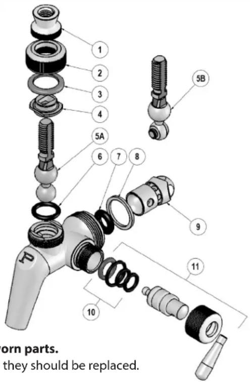
Follow these instructions if you need to take the faucet apart to replace worn parts.
Note: Anytime the Front Seat (I), O-ring (H) or Coupling Gasket(s) are removed, they should be replaced.
Always use OEM replacement parts.
TO DISASSEMBLE:
- If faucet is USED, soak faucet in warm cleaning solution for 1-2 minutes to free up bonnet and handle jacket. If the faucet is NEW, submerge the faucet in warm water for 5 seconds.
- Unscrew and remove Jacket (1).
- Unscrew and remove Compression Bonnet (2).
- Remove Coupling Gasket (8) only if cut or worn.
- To remove the Handle Lever Assembly (5A or 5B), lift it upward and push back.
- To remove Front Seat (7) use a small screwdriver from the bonnet end of the faucet.
- To remove O-ring (6) use a small screwdriver from the bonnet end of the faucet.
- Inspect O-rings for wear or damage and replace as necessary.
- To remove flow control lever, unscrew cap and pull out.
- Remove flow control compensator from rear of faucet.
TO ASSEMBLE:
- Re-install O-ring (6) into O-ring groove from bonnet end (use a small blunt screwdriver).
- Re-install front Seat (7) into O-ring groove (use a small blunt screwdriver). Note: Seat must move freely in seat groove.
- Re-install Handle Lever Assembly (5A or 5B).
- Re-install Bearing Cup (4).
- Re-install Bonnet Washer (3) into Compression Bonnet (2).
- Re-install Compression Bonnet (2). Tighten by hand only. Do not use any tool, as this can damage the faucet.
- Re-install Handle Jacket (1).
- Re-install Coupling Gasket (8) if removed.
- Install flow control compensator into rear of faucet and orientate so level engagement hole is facing lever insertion hole.
- Install flow control lever, ensure pin on end of lever is aligned with compensator engagement hole and tighten cap.
Form No. 67952
Rev. 06.05.14
Brand : Perlick
Model : 650
Category : Beer dispenser