789-44 - Splitter Xantech - Free user manual and instructions
Find the device manual for free 789-44 Xantech in PDF.


| Brand | Xantech |
| Model | 789-44 |
| Product Type | Distributor / Connecting Block |
| Dimensions (W x D x H) | 2-15/16" x 1-3/4" x 13/16" (74.6 x 44.5 x 20.6 mm) |
| Power Supply | 12 V DC via 2.1 mm coaxial power jack; compatible with 781RG (200 mA) or 782-00 (1000 mA) |
| Inputs | 1 x 4-terminal screw plug-in; 1 x IR Receiver 3.5 mm stereo mini jack |
| Outputs | 4 x emitter ports (3.5 mm mono mini jacks), parallel driven with series 470 Ω resistors |
| Compatible Emitters | Xantech 282, 283, 284, 286 Mini Emitters (up to 8 individual emitters) |
| Status Terminal | Yes, for connecting status LED on compatible Xantech products (e.g., 780-80) |
| Mounting | Wall or shelf; includes two sheet-metal screws; any orientation |
| Expansion Capability | Provides emitter expansion for Xantech devices (e.g., 590, 710, 792-10, 795-20, 796-20) |
| Maximum IR Receivers (parallel) | Up to 12 (excluding SmartPads) |
| SmartPad Compatibility | Yes, virtually unlimited with adequate power supply |
| Caution | Use only Xantech IR receivers in the IR RCVR jack; do not plug emitters or other devices |
| Power Supply Caution | Do not parallel regulated power supplies; avoid unregulated adapters to prevent latch-up |
| Long Cable Compensation | For cables over 50 ft, connect a 470 Ω resistor between IR IN and GND (see Fig. 4) |
Frequently Asked Questions - 789-44 Xantech
User questions about 789-44 Xantech
0 question about this device. Answer the ones you know or ask your own.
Ask a new question about this device
Download the instructions for your Splitter in PDF format for free! Find your manual 789-44 - Xantech and take your electronic device back in hand. On this page are published all the documents necessary for the use of your device. 789-44 by Xantech.
USER MANUAL 789-44 Xantech
INSTALLATION INSTRUCTIONS
789.44 CONNECTING BLOCK
The Model 789-44 provides a quick low cost means of connecting Xantech IR receivers and keypads to four single or four dual emitters, with a power supply, in an infrared repeater system. It can also provide emitter expansion for various Xantech devices, such as the 590, 710, 792-10, 795-20, 796-20, etc.. The STATUS terminal provides a convenient tie point for voltage to drive the STATUS indicator on certain Xantech products, such as the 780-80 IR Receiver (refer to Fig. 3).
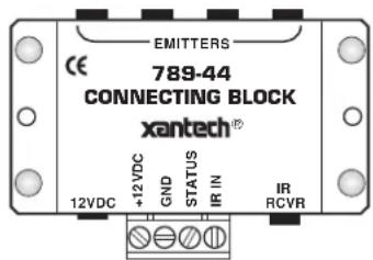
Fig. 1 Model 789-44 Connecting Block
SPECIFICATIONS
- Inputs: 1 - Screw type 4-terminal plug-in. 1 - IR Receiver "IR RCVR" 3.5mm stereo mini jack. (See Caution Note, Fig. 4)
- Outputs: 4 - Emitter ports (3.5mm mono mini jacks) parallel driven.
- Contains a 470 Ohm resistor in series with each emitter output.
• Xantech 282, 283, 284 & 286 Mini Emitters may be used. - Power requirements: 12 volts DC. Uses 781RG or 782-00 Power Supplies. Note: A power supply is not connected to the 789-44 when it is used as an emitter expander.
• 2.1 mm coaxial power jack. - Dimensions: 2-15/16" W x 1-3/4" D x 13/16" H
INSTALLATION
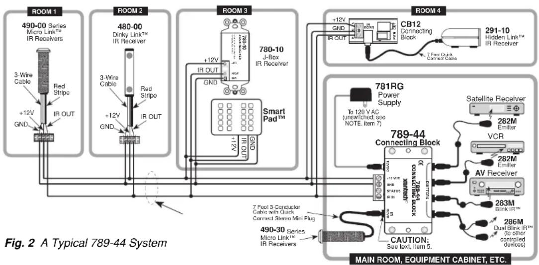
Fig. 2, illustrates a typical installation using the 789-44 in an IR repeater system. A variety of Xantech IR receivers and a keypad are shown. When configuring a system, please keep the following items in mind:
- More IR receivers may be wired in parallel, in the same manner as shown, up to a maximum of twelve. More than twelve is not recommended since IR noise picked up by the many IR receivers may cause erratic operation and reduce remote control range.
Note: This restriction does not apply to Xantech SmartPad keypads. These may be added virtually without limit, provided power supply requirements are taken into consideration. See item 3.
- Be sure to connect the +12V, IR OUT and GND of each IR Receiver and keypad to the respective +12VDC, IR IN and GND of the connecting block as shown.
- Xantech SmartPads may be used by themselves or together with IR receivers as shown. When you do this however, the higher current requirements of the keypads must be taken into consideration as follows:
a) Each 730-00 keypad draws 65 mA. A SmartPad _2 or 3 draws 85 ma.
b) Each IR receiver draws 10 to 20 mA (check specs. on actual model).
c) The max. current for proper operation from the 781RG Power Supply is 200 mA.
d) The max. current from the 782-00 Power Supply is 1000 mA.
e) When using combinations of keypads and receivers, do not exceed the max. current of the power supplies as noted above.
3. (Cont'd)
- For example, 2 keypads and several IR receivers could be used with one 781RG Power Supply and 12 keypads and 8 (or more) receivers could be used with one 782-00 Power Supply.
NOTE: To avoid current "hogging", never connect regulated power supplies, such as the 781RG or the 782-00, in parallel!
- CAUTION: Do not use unregulated 12V power supply adapters from other manufacturers. These may deliver excessive voltage to the IR receivers and cause them to "latch-up". When this occurs, the "talkback" LEDs and 283 Blink IR's (if used) will stay on continuously!
- For clarity, connections in Fig. 2 are shown going to a 3-conductor bus in a "daisy chain" fashion. In an actual installation, however, it is recommended that 4-conductor "home-runs" be pulled from each room to the 789-44 Connecting Block in the main room. The home-runs maintain higher power supply voltage to each IR receiver and keypad, and the extra 4th wire can be used for "STATUS" if desired (refer to Fig. 3).
- The "IR RCVR" jack on the 789-44 allows the 490-30 (and other Xantech IR Receivers with a cable having a 3.5 mm stereo mini plug) to be plugged directly into the 789-44. You can do this when the 789-44 Connecting Block is within reach of the 7-foot cable, such as when installing the 490-30 in a cabinet where the controlled equipment is behind closed doors.
flowchart
graph TD
    subgraph_Room_1["ROOM 1"]
        A["3-Wire Cable"] --> B["Red Stripe"]
        B --> C["IR OUT"]
        D["+12V GND"] --> E["IR OUT"]
        F["Room 2"]
        G["3-Wire Cable"] --> H["Red Stripe"]
        H --> I["+12V GND"]
        J["IR OUT"] --> K["IR OUT"]
    end

    subgraph_Room_2["ROOM 2"]
        L["3-Wire Cable"] --> M["Red Stripe"]
        M --> N["+12V GND"]
        O["IR OUT"] --> P["IR OUT"]
        Q["Room 3"]
        R["780-10 J-Box IR Receiver"] --> S["Smart Pad™"]
        T["+12V GND"] --> U["GND"]
        V["IR OUT"] --> W["GND"]
    end

    subgraph_Room_3["ROOM 3"]
        X["780-10 J-Box IR Receiver"] --> Y["Smart Pad™"]
        Z["+12V GND"] --> AA["GND"]
        AB["IR OUT"] --> AC["GND"]
        AD["Room 4"]
        AE["CB12 Connecting Block"] --> AF["7 Foot Quick Connect Cable"]
        AG["291-10 Hidden Link™ IR Receiver"] --> AH["291-10"]
    end

    subgraph Room_4
        AI["781RG Power Supply"] --> AJ["To 120 V AC (unswitched; see NOTE. item 7)"]
        AK["Satellite Receiver"] --> AL["VCR"]
        AM["VCR"] --> AN["AV Receiver"]
        AO["282M Emitter"] --> AP["Blink IR™"]
        AQ["282M Emitter"] --> AR["Blink IR™"]
        AS["283M"] --> AT["Blink IR™"]
        AU["286M Dual Blink IR™ (to other controlled devices)"] --> AV["Blink IR™"]
    end

    subgraph_Room_5["ROOM 5"]
        AW["490-30 Series Micro Link™ IR Receivers"] --> AX["7 Foot 3-Conductor Cable with Quick Connect Stereo Mini Plug"]
        AY["490-00 Series Micro Link™ IR Receivers"] --> AZ["7 Foot 3-Conductor Cable with Quick Connect Stereo Mini Plug"]
        BA["789-44 Connecting Block"] --> BB["CAUTION: See text, item 5"]

    end

    style Room_5 fill:#f9f,stroke:#333
    style Room_6 fill:#ccf,stroke:#333
    style Room_7 fill:#cfc,stroke:#333
    style Room_8 fill:#fcc,stroke:#333
    style Room_9 fill:#ffc,stroke:#333
    style Room_10 fill:#fcc,stroke:#333
    style Room_11 fill:#fcc,stroke:#333
    style Room_12 fill:#fcc,stroke:#333
    style Room_13 fill:#fcc,stroke:#333
    style Room_14 fill:#fcc,stroke:#333
    style Room_15 fill:#fcc,stroke:#333
    style Room_16 fill:#fcc,stroke:#333
    style Room_17 fill:#fcc,stroke:#333
    style Room_18 fill:#fcc,stroke:#333
    style Room_19 fill:#fcc,stroke:#333
    style Room_20 fill:#fcc,stroke:#333
    style Room_21 fill:#fcc,stroke:#333
    style Room_22 fill:#fcc,stroke:#333
    style Room_23 fill:#fcc,stroke:#333
    style Room_24 fill:#fcc,stroke:#333
    style Room_25 fill:#fcc,stroke:#333
    style Room_26 fill:#fcc,stroke:#333
    style Room_27 fill:#fcc,stroke:#333
    style Room_28 fill:#fcc,stroke:#333
    style Room_29 fill:#fcc,stroke:#333
    style Room_30 fill:#fcc,stroke:#333
    style Room_31 fill:#fcc,stroke:#333
    style Room_32 fill:#fcc,stroke:#333
    style Room_33 fill:#fcc,stroke:#333
    style Room_34 fill:#fcc,stroke:#333
    style Room_35 fill:#fcc,stroke:#333
    style Room_36 fill:#fcc,stroke:#333
    style Room_37 fill:#fcc,stroke:#333
    style Room_38 fill:#fcc,stroke:#333
    style Room_39 fill:#fcc,stroke:#333
    style Room_40 fill:#fcc,stroke:#333
    style Room_41 fill:#fcc,stroke:#333
    style Room_42 fill:#fcc,stroke:#333
    style Room_43 fill:#fcc,stroke:#333
    style Room_44 fill:#fcc,stroke:#333
    style Room_45 fill:#fcc,stroke:#333
    style Room_46 fill:#fcc,stroke:#333
    style Room_47 fill:#fcc,stroke:#333
    style Room_48 fill:#fcc,stroke:#333
    style Room_49 fill:#fcc,stroke:#333
    style Room_50 fill:#fcc,stroke:#333
CAUTION: Plug only Xantech IR Receivers equipped with a stereo mini plug into the IR RCVR jack. Do not plug in emitters or other devices; it will destroy emitter & damage power supplies!
- The emitter ports are driven in parallel with a 470 Ohm resistor connected in series with each port. The resistors ensure proper current sharing to each emitter. When using less than 4 emitters, you may plug them into any of the 4 emitter ports without regard to order.
- Because of this current sharing feature, you may plug in any combination of the 282, 283, 284 & 286 series of emitters (up to a maximum of 8 individual emitters) to drive the desired number of devices.
NOTE: Be sure the 781RG Power Supply is plugged into an un-switched AC outlet. This maintains the system in "standby" operation so that power-on commands can be sent to the controlled equipment.
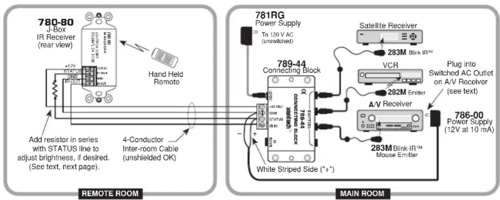
Fig. 3 Using the STATUS terminal in a typical system (see text, pg 4).
Using The "STATUS" Terminal on the 789-44
Fig. 3 illustrates a single zone system where the Status LED on a Xantech 780-80 IR Receiver, in the remote room, shows the ON/OFF status of an A/V receiver.
- The STATUS and GND terminals on the 789-44 provide convenient tie points for the voltage that drives STATUS indicators on certain Xantech products (such as the 780-80 IR Receiver).
To connect such a system, proceed as follows:
- Be sure all power plugs for the A/V system are un-plugged before proceeding with the following connections.
- Plug a 12V adapter, such as the Xantech 786-00 Power Supply, into the switched AC Outlet on the back of the A/V receiver (or integrated amplifier, preamp, etc.).
- The 12V leads of the adapter (cut attached plug off) are then connected between the STATUS and GND terminals on the 789-44 ("+" to STATUS, "-" to GND).
- You would then connect the 4-conductor inter-room cable between the 789-44 and the 780-80 as shown in Fig. 3.
- If you wish to adjust the brightness of the Status LED, place a resistor in series with the STATUS lead as shown in Fig. 3. Use a value that achieves the desired brightness level (usually 1k Ohm to 10k Ohm, 1/8 watt).
CAUTION NOTE
When using long lengths (>50 ft.) of inter-room shielded cable, it may be necessary to connect a 470 Ohm 1/8 Watt resistor between IR IN and GND at the connector terminals of the 789-44. Refer to Fig.4.
The resistor discharges the cable capacitance more quickly, allowing IR codes of high bit rates to pass without data loss.
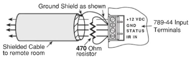
Fig. 4 470 Ohm Capacitance Discharge Resistor
MOUNTING
The 789-44 can be conveniently mounted to a wall or shelf by using the two sheet-metal screws supplied. The unit may be mounted in any orientation to accommodate the installation.
Brand : Xantech
Model : 789-44
Category : Splitter