XVCO100 - Audio/Video Accessories Xantech - Free user manual and instructions
Find the device manual for free XVCO100 Xantech in PDF.

| Brand | Xantech |
| Model | XVCO100 |
| Product Type | In-wall stereo speaker volume control with impedance matching |
| Power Handling (Continuous) | 100 Watts |
| Power Handling (Peak) | 300 Watts |
| Impedance Matching | Adjustable for up to 8 speaker pairs (1, 2, 4, 8 pairs) |
| Frequency Response | 20 Hz – 20 kHz ±1 dB |
| Speaker Terminals | 16 gauge, Quick Connect (detachable) |
| Speaker Compatibility | 4, 6, or 8 ohm systems |
| Grounding | Isolated left- and right-channel grounds for bridged amplifier safety |
| Volume Control Type | Rotary or slider (model dependent) |
| Mounting Requirement | Minimum 20 cu. in. J-box or Mud Ring |
| Installation Tools | Screwdriver and wire strippers |
| Recommended Wire | 16-gauge stranded copper speaker wire (14-gauge for runs over 100 ft) |
| Compliance | UL Listed |
| Warranty | 5 years limited (effective for products sold after July 1, 2006) |
| Face Plate | Removable, replaceable with correct color face plate |
| Switching Performance | Fluid, pop-free volume adjustments |
Frequently Asked Questions - XVCO100 Xantech
User questions about XVCO100 Xantech
0 question about this device. Answer the ones you know or ask your own.
Ask a new question about this device
Download the instructions for your Audio/Video Accessories in PDF format for free! Find your manual XVCO100 - Xantech and take your electronic device back in hand. On this page are published all the documents necessary for the use of your device. XVCO100 by Xantech.
USER MANUAL XVCO100 Xantech
INSTALLATION INSTRUCTIONS
XANTECH VOLUME CONTROLS
Installation Instructions XVC Series Volume Controls
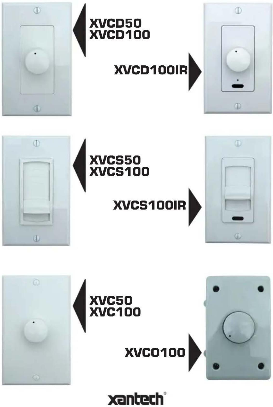
Xantech's premier product line of XV volume controls are in-wall mountable stereo speaker volume control with impedance matching capability. From one to eight pairs or stereo speakers may be driven from one stereo power amplifier, using an equal number of XV volume controls. It maintains correct impedance matching between the amplifier and the speakers by the use of instant setting jumpers on the control. This eliminates the need for separate impedance matching components in multi-room installations.
Features and Benefits
• XVC50, XVD50, XVC50
Power handling: 50 Watts continuous, 150 Watts peak
• XVC100, XVD100, XVCS100, XVCO100, XVCD100IR, XVCS100IR
Power handling: 100 Watts continuous, 300 Watts peak
- All Models
Adjustable impedance matching for up to 8 speaker pairs (1, 2, 4, 8 pairs)
Frequency response: 20Hz-20kHz ±1 dB
Speaker Terminals: 16 gauge, Quick Connect (detachable)
Mounting: Minimum 20 cu. in. J-box or Mud Ring.
Note: Be sure to check fit before choosing J-boxes!
Isolated left- and right-channel grounds ensure safety with any bridged amplifier.
Fluid, pop-free switching during volume adjustments.
Compatible with 4-, 6-, or 8-ohm speaker systems.
UL Listed to comply will all local building codes.
Installation requires only a screwdriver and wire strippers.
Installation Requirements
You will need at the very least, a 18 " slotted screwdriver, a 14 " slotted screwdriver, wire cutters and wire strippers.
The recommended speaker wire to be used is 16-gauge stranded copper speaker wire. For runs longer than 100 feet, we recommend 14-gauge stranded copper speaker wire. Never use solid-core wire such as aluminum or Romex wire.
Most installations in the United States require a special fire rated wire (CL-2 or CL-3) for speaker wire installed within a wall. Consult your local building codes to find out what kind of wire is required.
Be sure to observe proper polarity when connecting a system. The positive terminals should always be connected to the positive wire. The negative terminals should always be connected to the negative wire. Failure to do so will result in poor phasing and possible system malfunctions.
Some areas allow the installation of the volume control to be placed in the same junction box as a high voltage connection (120VAC) and divided by a low-voltage partition. This is not recommended as the speaker wires may pick up interference from the high voltage (120VAC) power lines. Again, consult your local building codes to verify the proper way to install the product.
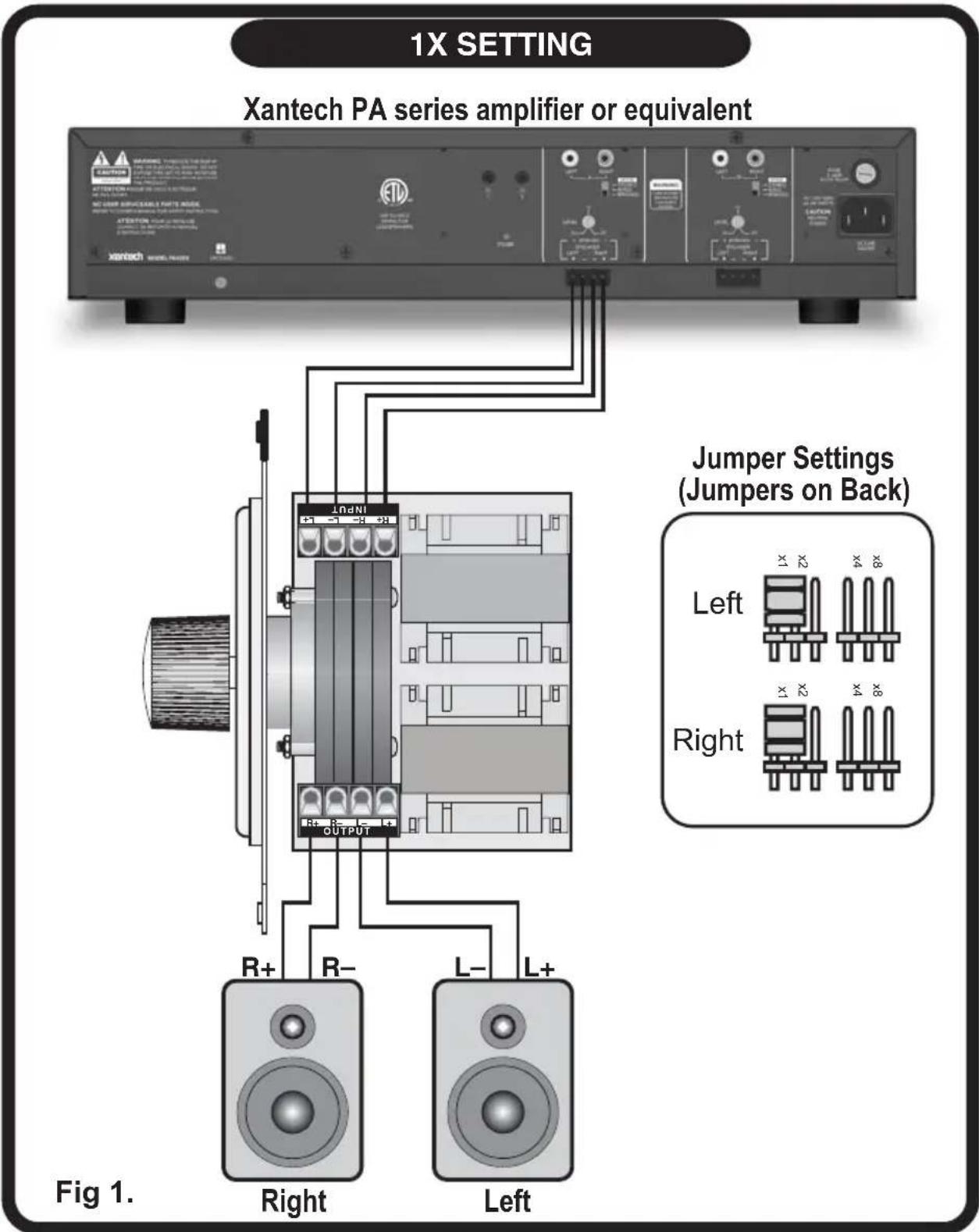
Impedance Jumper Settings for Identical Impedance
How to use the impedance jumper setting chart:
1) Determine the minimum amplifier impedance (typically either 4- or 8-Ohm). This information can usually be found next to the speaker outputs located on the receiver or amplifier. If in doubt, consult the receiver and/or amplifier instruction manual.
2) Next, determine the impedance of a single speaker that will be used. Use the left-most column.
3) Move to the right of the chart and find the number of speaker pairs that you plan to connect to the volume control.
4) Finally, move up the column to the very top row. This row will provide the jumper setting solution. Change the jumper on the volume control to complete the impedance jumper setting procedure. Both jumpers must be changed appropriately (see diagram in Fig. 1)
| Jumper Settings | |||||
| x1 x2 x4 x8 | |||||
| Speaker Impedance | 8Ohm | 1 PAIR | 2 PAIRS | 4 PAIRS | 8 PAIRS |
| 6Ohm | - 1 PAIR | 2 PAIRS | 4 PAIRS | ||
| 4Ohm | - 1 PAIR | 2 PAIRS | 4 PAIRS | ||
CHART A: 8 Ohm Minimum Amplifier
| Jumper Settings | |||||
| x1 x2 x4 x8 | |||||
| Speaker Impedance | 8 Ohm | 1 PAIR | 4 PAIR 8 PAIRS - | ||
| 6 Ohm | 1 PAIR | 2 PAIRS 4 PAIRS 8 PAIRS | |||
| 4 Ohm | 1 PAIR | 2 PAIRS 4 PAIRS 8 PAIRS | |||
CHART B: 4 Ohm Minimum Amplifier
Example 1:
Two pairs of 8 Ohm ceiling speakers are to be used with two volume controls, all driven by a single amplifier rated for 8 Ohm minimum safe operating load impedance.
1) Refer to "CHART A", 8 Ohm Minimum Amplifier.
2) In the first column, find "8 Ohms".
3) Follow the row to the right until you find "2 PAIR".
4) Follow the column up to the very top row and find that the jumper setting should be set to "x2" for both volume controls.
Installation Tip – Setting the Volume
1) Set your receiver and/or amplifier to the lowest possible volume setting.
2) Turn all the volume controls to maximum volume (up position for slider volume controls, full clockwise position for rotary volume controls).
3) Turn up the receiver and/or amplifier volume setting until you reach the maximum listening level desired.
4) Finally, lower the volume control level. Volume setting is now complete.
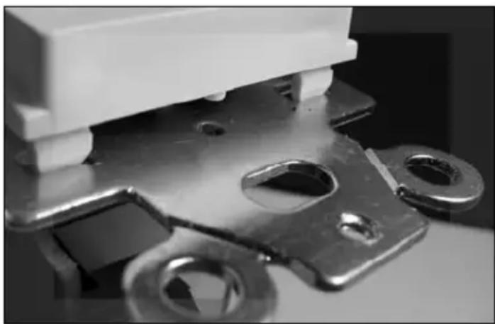
Changing the Face Plate
natural_image
Close-up of a metallic electrical socket with mounting holes and a white housing (no visible text or symbols)1) Gently press the tabs up on all four corners.
2) Lift the face plate off the metal frame and remove.
3) Replace with the correct color face plate.
Single Zone, Single Speaker Pair Volume Control Application
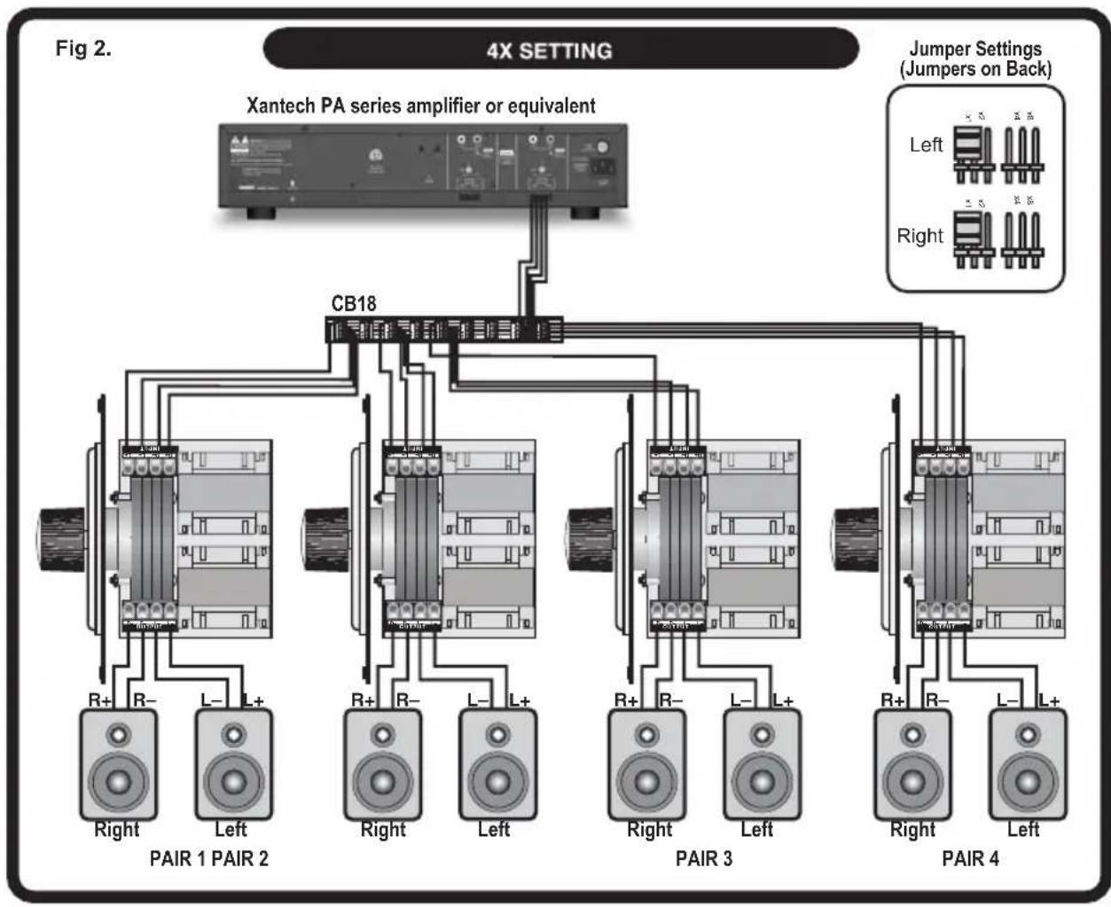
Multiple Zone, Single Speaker Pair Volume Control Application
flowchart
graph TD
    A["4X SETTING"] --> B["Xantech PA series amplifier or equivalent"]
    B --> C["CB18"]
    C --> D["PAIR 1"]
    C --> E["PAIR 2"]
    C --> F["PAIR 3"]
    C --> G["PAIR 4"]
    D --> H["Right"]
    D --> I["Left"]
    E --> J["Right"]
    E --> K["Left"]
    F --> L["Right"]
    F --> M["Left"]
    G --> N["Right"]
    G --> O["Left"]
    style A fill:#f9f,stroke:#333
    style B fill:#ccf,stroke:#333
    style C fill:#cfc,stroke:#333
    style D fill:#fcc,stroke:#333
    style E fill:#cff,stroke:#333
    style F fill:#ffc,stroke:#333
    style G fill:#cfc,stroke:#333
Single Zone, Single Speaker Pair Volume Control and IR Receiver Application
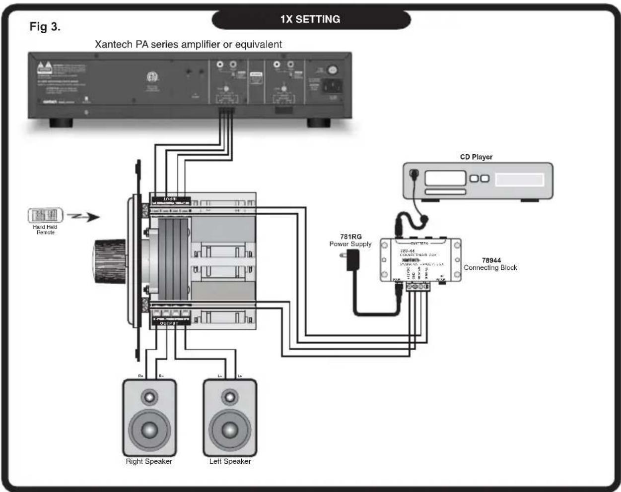
Note: Applies to Model XVCD100IR, XVCS100IR only
CB18 Connecting Block (not included)
The CB18 provides a convenient way to parallel many wires onto a 4 conductor bus. You can easily connect many home run leads from volume controls to the output terminals of a main amplifier.
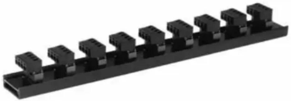
natural_image
3D rendering of a black industrial connector block assembly (no text or symbols visible)The CB18 features the following:
- Nine 4-terminal plug-in connectors on a 4-conductor bus.
- One-in eight-out or eight-in one-out capability.
- Adhesive backed labels are included for attachment to the plug-in terminals so that the speaker lead connections can easily be identified.
- High current design allows amplifiers rated as high as 500 Watts to be used.
- Screw terminals handle wire sizes from 24 to 12 gauge.
- Dimensions: 11- 14 " x 1- 14 " x 1- 14 ".
Warranty Statement
Xantech 5 Year Limited Warranty
(Effective for products sold after July 1, 2006)
Xantech Corporation ("Xantech") warrants to the holder of a valid proof of purchase as the first end-user purchaser ("You"), its products to be free from defects in materials and workmanship for the periods specified above from the date of purchase. This limited warranty extends only to You for product purchased and used in the United States of America. For product purchased outside of the United States of America, the terms of this warranty apply EXCEPT that You must contact the Xantech authorized distributor in your region for warranty services. Product is not intended for end user installation. If within the applicable warranty period above You discover such item was not as warranted above and You promptly notify Xantech in writing, Xantech shall repair or replace the items at its option. Xantech may elect which remedy or combination of remedies to provide in its sole discretion. Xantech may use functionally equivalent reconditioned/refurbished/pre-owned or new products or parts under this limited warranty. This warranty shall not apply (a) to product which shall have been installed by other than an authorized Xantech installer, (b) to installed product which is not installed to Xantech's specifications, (c) to product which shall have been repaired or altered by others than Xantech, (d) to charges for installation or set up or adjustment of customer controls, (e) to product that has suffered normal cosmetic deterioration (f) to product which shall have been subjected to negligence, misuse, abuse, accident, or damage by circumstances beyond Xantech's control, including, but not limited to, lightning, flood, electrical surge, tornado, earthquake, or any other catastrophic events beyond Xantech's control, or (g) to product which shall have been subjected to improper operation, connected equipment failure or malfunction, inadequate packing or shipping damage, maintenance or storage, or to other than normal use of service. The foregoing warranties do not cover reimbursement for labor, transportation, shipping, removal, installation, or other expenses which may be incurred in connection with repair or replacement. All claims for product shipping damage must be processes within 3 days of receipt by You. A Xantech Return Authorization (RA) must be obtained from Xantech by You, your installer or your distributor for Product covered under this warranty. Covered product must be sent to Xantech together with proof of purchase, RA number, prepaid and insured to Xantech. Freight collect shipments will be refused. Risk of loss or damage in transit is borne by the sender. Xantech's warranty does not cover Products which have been received improperly packaged, altered, or physically damaged. Products will be inspected upon receipt. Except as may be expressly provided and authorized in writing by Xantech, Xantech shall not be subject to any other obligations or liabilities whatsoever with respect to equipment manufactured or sold by Xantech or services rendered by Xantech.
THE FOREGOING WARRANTIES ARE EXCLUSIVE AND IN LIEU OF ALL OTHER EXPRESSED AND IMPLIED WARRANTIES, INCLUDING BUT NOT LIMITED TO IMPLIED WARRANTIES OF MERCHANTABILITY AND FITNESS FOR A PARTICULAR PURPOSE.
ATTENTION: TO OUR VALUED CONSUMERS
To insure that consumers obtain quality pre-sale and after-sale support and service, Xantech products are sold exclusively through authorized dealers and authorized distributors. Xantech products are not sold online. The warranties on Xantech products are NOT VALID if the products have been purchased from an unauthorized distributor or an online E-tailer. In order to determine if your Xantech re-seller is authorized, please call Xantech (800) 843 - 5465.
Xantech Corporation
13100 Telfair Avenue, 2/F
Sylmar, CA 91342
Installation Instructions, Volume Controls
© 2006 Xantech Corporation, Document #08905078A
This document is copyright protected. No part of this manual may be copied or reproduced in any form without prior written consent from Xantech Corporation.
Xantech Corporation shall not be liable for operational, technical, or editorial errors/omissions made in this document.
- INSTALLATION INSTRUCTIONS
- Installation Instructions XVC Series Volume Controls
- Features and Benefits
- Installation Requirements
- Impedance Jumper Settings for Identical Impedance
- Example 1:
- Installation Tip – Setting the Volume
- Changing the Face Plate
- Single Zone, Single Speaker Pair Volume Control Application
- Single Zone, Single Speaker Pair Volume Control and IR Receiver Application
- CB18 Connecting Block (not included)
- Warranty Statement
Brand : Xantech
Model : XVCO100
Category : Audio/Video Accessories