
CR-A149 - Alarm clock radio COBY - Free user manual and instructions
Find the device manual for free CR-A149 COBY in PDF.


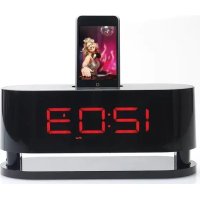
| Product Type | Projection AM/FM Alarm Clock Radio with Temperature Display |
| Brand | Coby |
| Model | CR-A149 |
| Power Supply | AC 120V ~60Hz, 5W |
| Battery Backup | 3V CR2025 Lithium x 3 (not included) |
| Remote Sensor Battery | 1.5V AAA x 2 (not included) |
| Radio Bands | AM, FM |
| AM Frequency Range | 530 - 1710 kHz |
| FM Frequency Range | 88 - 108 MHz |
| RCC Carrier Frequency | 60 kHz |
| RCC Station | WWVB |
| Audio Output | Full-range speaker |
| Output Power | 350 mW |
| Speaker Impedance | 8 Ω |
| Alarm Types | Dual alarm timers (Alarm 1 & Alarm 2), wake to radio or buzzer |
| Snooze Duration | 9 minutes |
| Sleep Timer Options | 90, 60, 30, 15 minutes |
| Projection Display | Dual projectors for time and indoor/outdoor temperature |
| Temperature Range (Indoor) | 0 - 50°C / 32 - 122°F |
| Temperature Range (Outdoor) | -20 - 60°C / -4 - 140°F |
| Clock Synchronization | Automatic daily sync with US atomic clock |
| Safety Features | Polarized plug, shock hazard warning, overloading protection |
| Cleaning | Unplug, use damp cloth only |
| Service | Refer to qualified service personnel |
Frequently Asked Questions - CR-A149 COBY
User questions about CR-A149 COBY
0 question about this device. Answer the ones you know or ask your own.
Ask a new question about this device
Download the instructions for your Alarm clock radio in PDF format for free! Find your manual CR-A149 - COBY and take your electronic device back in hand. On this page are published all the documents necessary for the use of your device. CR-A149 by COBY.
USER MANUAL CR-A149 COBY
Projection AM/FM Alarm Atomic Clock Radio with Temperature Display
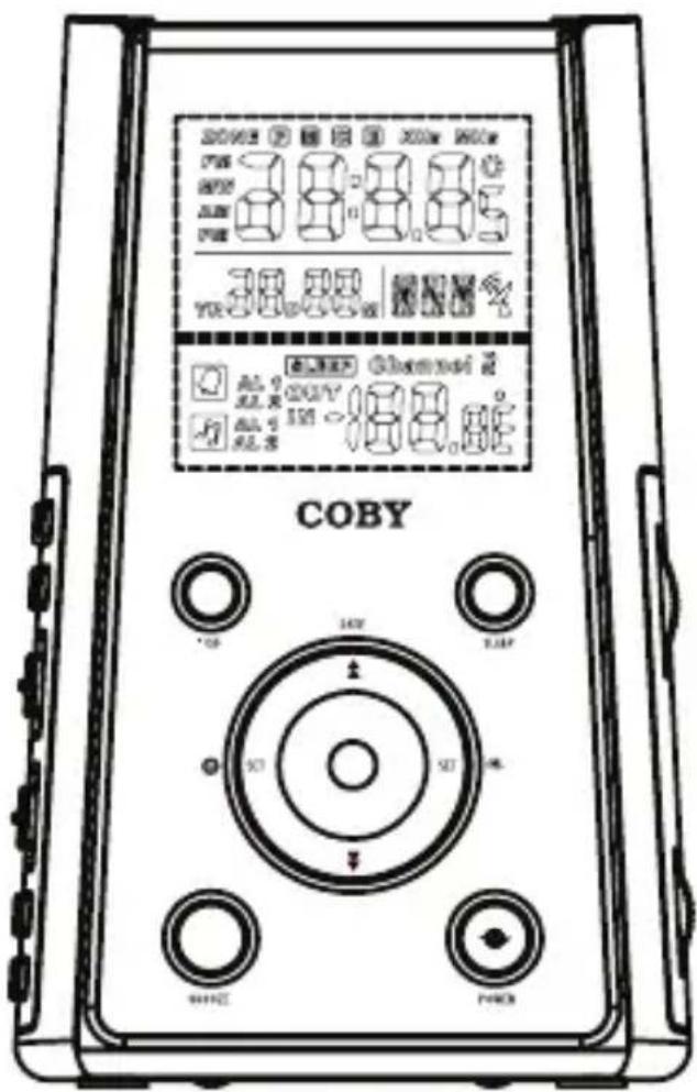
INSTRUCTION MANUAL
Please read this manual carefully before operation
PRECAUTIONS
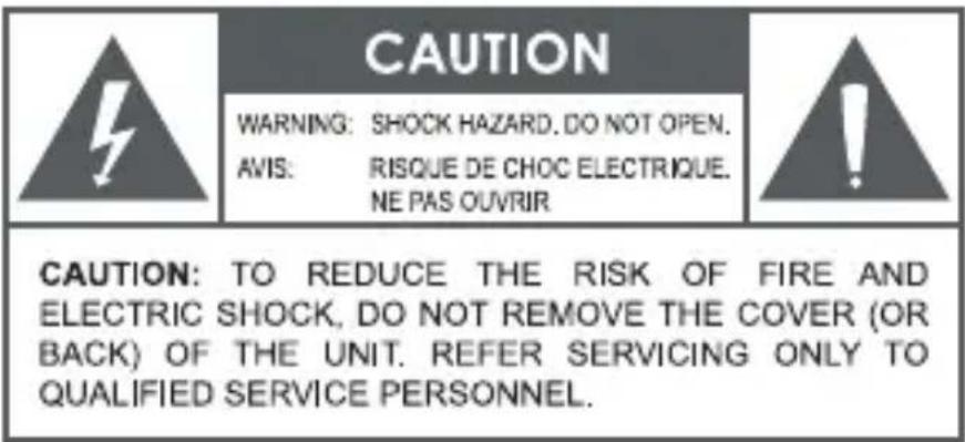

The lightning flash with arrowhead symbol within an equilateral triangle is intended to alert the user to the presence of uninsulated “dangerous voltage” within the product’s enclosure that may be of sufficient magnitude to constitute a risk of electric shock.
The exclamation point within an equilateral triangle is intended to alert the user to the presence of important operation and servicing instructions in the literature accompanying the appliance.
For Customer Use:
Enter below the serial number that is located on the unit. Retain this information for future reference.
Model No. CR-A149
Serial No.
WARNING:
To prevent fire or shock hazard, do not expose this device to rain or moisture. Dangerous high voltage is present inside the enclosure. Do not open the cabinet.
CAUTION:
To prevent electric shock, match wide blade of plug to wide slot of outlet and fully insert.

For recycling or disposal information about this product, please contact your local authorities or the Electronics Industries Alliance: www.eiae.org.
IMPORTANT SAFETY INSTRUCTIONS
- Read Instructions: All the safety and operating instructions should be read before the product is operated.
- Retain Instructions: The safety and operating instructions should be retained for future reference.
- Heed Warnings: All warnings on the product and in the operating instructions should be adhered to.
- Follow Instructions: All operating and usage instructions should be followed.
- Cleaning: Unplug this product from the wall outlet before cleaning. Do not use liquid cleaners or aerosol cleaners. Use a damp cloth for cleaning.
-
Attachments: Use only attachments recommended by the manufacturer. Use of other attachments may be hazardous.
-
Water and Moisture: Do not use this product near water (e.g., near a bath tub, washbowl, kitchen sink, laundry tub, in wet basements, or near a swimming pool and the like).
-
Accessories: Do not place this product on an unstable cart, stand, tripod, bracket, or table. Use only with carts, stands, tripods, brackets, or tables recommended by the manufacturer or sold with the product. Any mounting of the product should follow the manufacturer's instructions and should use a mounting accessory recommended by the manufacturer.

natural_image
Symbolic icon of a person pushing a large stack of objects inside a circle (no text or symbols)-
A product and cart combination should be moved with care. Quick stops, excessive force, and uneven surfaces may cause the product and cart combination to overturn.
-
Ventilation: Slots and openings in the cabinet are provided for ventilation to ensure reliable operation of the product and to protect it from overheating. These openings should never be blocked by placing the product on a bed, sofa, rug, or other similar surface. This product should not be placed in a built-in installation such as a bookcase or rack unless proper ventilation is provided or the manufacturer instructions have been adhered to.
-
Power Sources: This product should be operated only from the type of power source indicated on the rating label. If you are not sure of the type of power supply to your home, consult your product dealer or local power company. For products intended to operate from battery power or other sources, refer to the operating instructions.
-
Grounding or Polarization: This product may be equipped with a polarized alternating-current line plug that has one blade wider than the other. This plug will only fit into the power outlet in one direction. This is a safety feature. If you are unable to insert the plug fully into the outlet, try reversing the direction of the plug. If the plug should still fail to fit, contact an electrician to replace the obsolete outlet. Do not defeat the safety purpose of the polarized plug.
IMPORTANT SAFETY INSTRUCTIONS
-
Power-Cord Protection: Power supply cords should be routed so that they are not likely to be walked on or pinched by items placed upon or against them, paying particular attention to cords at plugs, convenience receptacles, and at the point which they exit from the product.
-
Protective Attachment Plug: The product may be equipped with an attachment plug with overload protection. This is a safety feature. See the operating instructions for replacement or directions to reset the protective device. If replacement of the plug is required, be sure the service technician has used a replacement plug that has the same overload protection as the original plug as specified by the manufacturer.
-
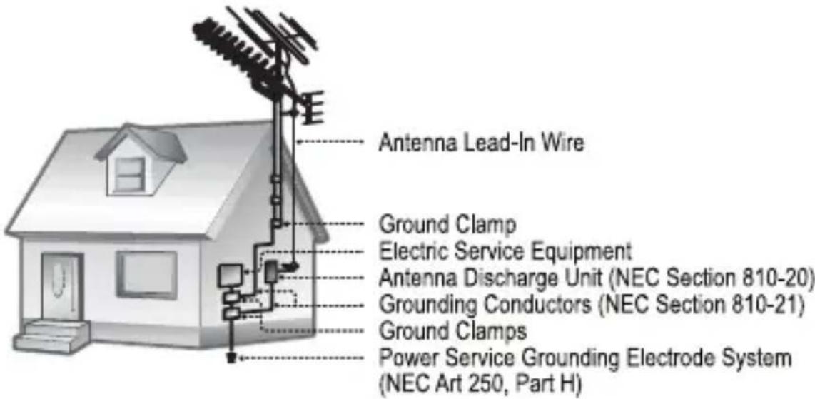
Outdoor Antenna Grounding: If an outside antenna is connected to the product, be sure the antenna system is grounded so as to provide some protection against voltage surges and built-up static charges. Article 810 of the National Electrical Code, ANS/NFPA 70 provides information with regard to proper grounding of the mast and supporting structure, grounding of the lead-in wire to an antenna-discharge unit, size of grounding conductors, location of antenna-discharge unit, connection to grounding electrodes, and requirements for the grounding electrode (see figure).
-
Lightning: For added protection for this product, unplug it from the wall outlet and disconnect the antenna or cable system during a lightning storm or when it is left unattended and unused for long periods of time. This will prevent damage to the product due to lightning or power-line surges.
-
Power Lines: An outside antenna system should not be located in the vicinity of overhead power lines or other electric light or power circuits, or where it can fall into such power lines or circuits. When installing an outside antenna system, extreme care should be taken to keep from touching such power lines or circuits, as contact with them might be fatal.
IMPORTANT SAFETY INSTRUCTIONS
- Overloading: Do not overload wall outlets, extension cords, or integral convenience receptacles as this can result in a risk of fire or electric shock.
- Object and Liquid Entry: Never push objects of any kind into this product through openings as they may touch dangerous voltage points or shout-out parts that could result in a fire or electric shock. Never spill liquid of any kind on the product.
- Servicing: Do not attempt to service this product yourself as opening or removing covers may expose you to dangerous voltage or other hazards. Refer all servicing to qualified service personnel.
- Damage Requiring Service: Unplug this product from the wall outlet and refer servicing to qualified service personnel under the following conditions: a) when the power-supply or plug is damaged; b) if liquid has been spilled or if objects have fallen into the product; c) if the product has been exposed to rain or water; d) if the product does not operate normally by following the operating instructions. Adjust only those controls that are covered by the operating instructions as improper adjustment of other controls may result in damage and will often require extensive work by a qualified technician to re-store the product to its normal operation; e) if the product has been dropped or damaged in any way; f) when the product exhibits a distinct change in performance—this indicates a need for service.
- Replacement Parts: When replacement parts are required, be sure that your service technician has used replacement parts specified by the manufacturer or have the same characteristics as the original part. Unauthorized substitutions may result in fire, electric shock, or other hazards.
- Safety Check: Upon completion of any service or repairs to this product, ask the service technician to perform safety checks to ensure that the product is in proper operating condition.
- Wall or Ceiling Mounting: The product should be mounted to a wall or ceiling only as recommended by the manufacturer.
- Heat: The product should be situated away from heat sources such as radiators, heat registers, stoves, or other products (including amplifiers) that produce heat.
TABLE OF CONTENTS
PRECAUTIONS 2
IMPORTANT SAFETY INSTRUCTIONS .... 3
TABLE OF CONTENTS ...... 6
FEATURES 7
GETTING STARTED 8
CR-A149 at a Glance 8
Top View 8
Front View 8
Rear View 8
Right View....9
Left View 9
Power Connection ....10
AC Power 10
Battery Backup 10
Reset 10
Preparing the CR-A149 for Use.... 11
CLOCK/ALARM MODE 12
Setting the Clock Time and Date ....12
Setting the Alarm Timer....13
Turning the Alarm Timer On/Off (Alarm Mode) 14
Snooze Function 14
Setting the Sleep Timer ....15
TEMPERATURE READING 16
Indoor Temperature 16
Outdoor Temperature 16
Wireless Outdoor Temperature Sensor 16
PROJECTION SYSTEM 18
RADIO MODE 19
Basic Operation ....19
Tuning 19
Reception 19
TROUBLESHOOTING 20
SPECIFICATIONS 21
FEATURES
Thank you for purchasing a COBY CR-A149. Please read through this manual carefully in order to have a better understanding of the performance and features of your alarm clock radio.
Dual projectors display the time and indoor/outdoor temperature
♦ Wireless outdoor temperature transmitter (max. 100' operating distance)
◆ Automatic daily clock synchronization with the official US atomic clock (accurate to within one second)
♦ Digital Time and Date Display with Backlight
✦ Dual Alarm Clock Settings
✦ Snooze/Sleep Function
✦ Wake to Music or Buzzer
★ AM/FM Radio
GETTING STARTED
CR-A149 at a Glance
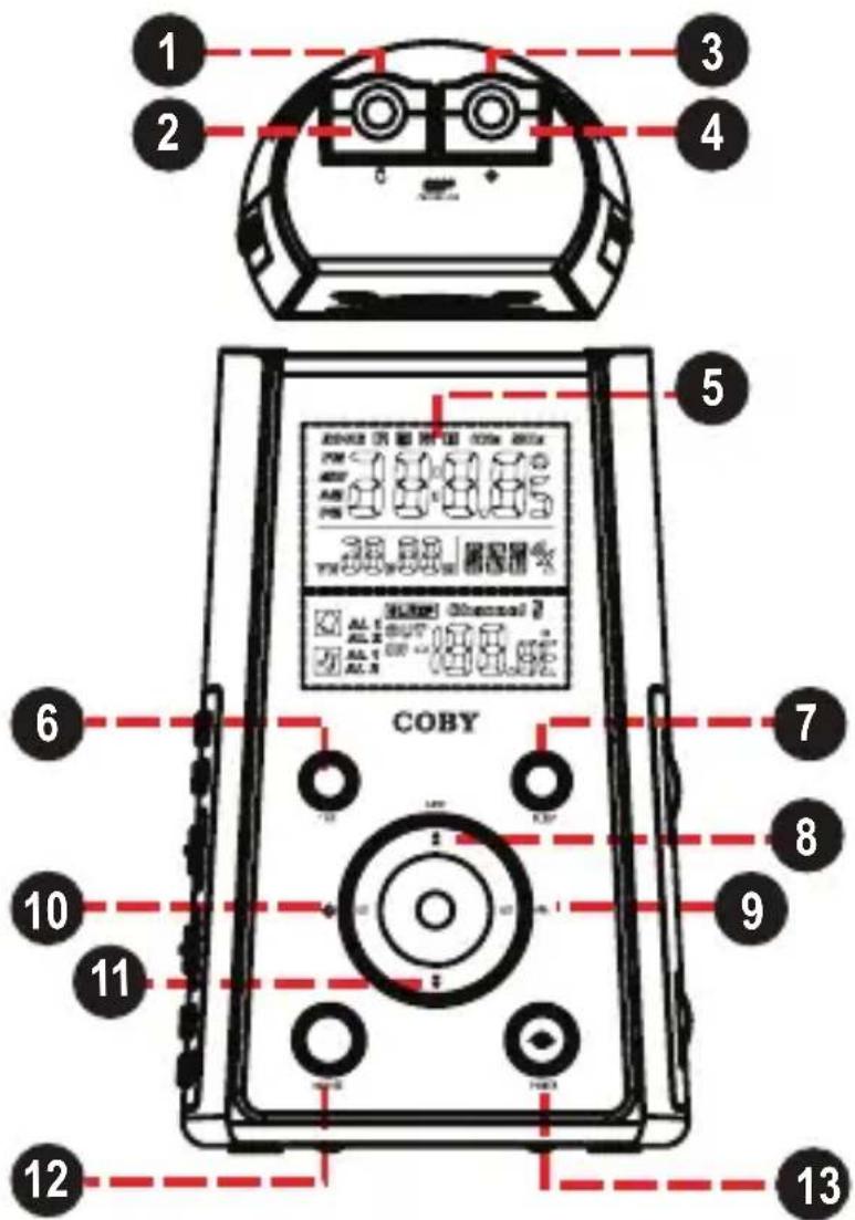
Top View
- Temperature Focus Dial
- Temperature Projector
- Clock Focus Dial
- Clock Projector
Front View
- Clock Display
- Temperature Mode
- Sleep
- Date / Up
- Alarm Set
- Clock Set
- Down
- Snooze
- Power
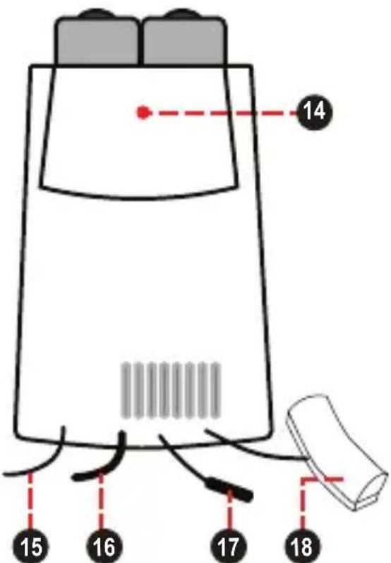
Rear View
- Reset Button
- FM Antenna
- AC Power Cord
- Temperature Sensor (Indoor)
- RCC Antenna (Radio Controlled Clock)
GETTING STARTED
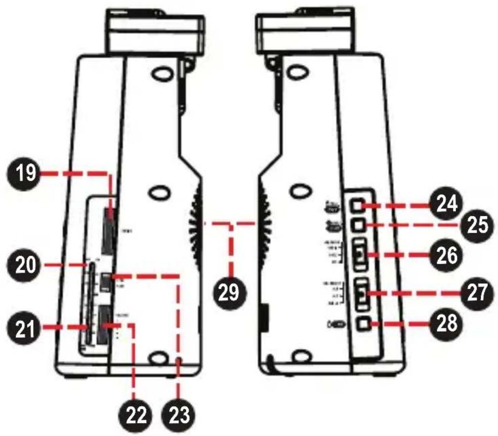
Right View
- Radio Tuning Dial
- Radio Frequency Band
- Radio Tuning Indicator
- Volume Level Dial
- Radio Band Switch (FM, AM)
Left View
- Temperature Projection (On/ Off)
- Clock Projection (On/Off)
- Alarm Mode Switch (Radio, Buzz, Off)
- Alarm Select (Alarm 1, Alarm 2, Alarm 1+2)
- Temperature Select (Indoor/Outdoor)
- Speaker
Power Connection
AC Power
This unit runs on AC 120V power.
Plug the AC Power Cord into a 120V household electrical wall outlet.
Do not connect the power plug to a power outlet other than that which is indicated here or on the label as this may result in the risk of fire or electric shock.
Do not handle the power plug with wet hands. Doing so may cause electric shock.
Battery Backup
The battery backup function maintains the clock time should the AC power be interrupted. When power is restored, the correct time will be displayed.
The battery compartment is located on the bottom of the unit. Load 3 x CR2025 lithium batteries (not included) in the battery compartment. Make sure that the positive (+) and negative (-) battery terminals are attached to the corresponding terminals on the plate in the battery compartment

The time will not be displayed nor will any functions be available during power failure. Battery backup maintains the time, only.
Reset
To reset the unit, press the RESET button located on the rear of the unit (behind the projectors. Reset the unit if it is not performing as expected and whenever the remote temperature sensor's batteries are changed. Resetting the unit will return all settings to their factory-default state and all stored data will be lost (e.g., alarm and clock settings).
Preparing the CR-A149 for Use
Plug the clock into an AC 120V outlet.
Press the RESET button located on the rear of the clock. Upon resetting the clock:
✨ The display will light up and flash
The temperature will be displayed for 4 seconds
The remote unit will search for the 433MHz transmission signal in 5 minutes
The main unit will start searching for the RCC (Radio Controlled Clock) signal automatically. The RCC signal will synchronize your clock's time and date (including Daylight Savings Time).
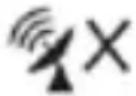
✿ An animated antenna dish icon indicates that the unit is searching for a signal.
✨ The antenna dish icon indicates that a signal has been received.
✿ The unit will stop searching after 10 minutes if a signal cannot be received
| Reception signal | No signal |
 |  |

It will take up to 10 minutes for the signal to synchro - nize the clock time.
RCC synchronization may be turned on or off by holding the snooze button for 3 seconds.
For best results, place the RCC antenna near a window with a clear view of the sky. Keep the RCC antenna away from metal or electrical objects.
CLOCK/ALARM MODE
Setting the Clock Time and Date
It is not necessary to set the clock time unless you cannot receive the RCC synchronization signal. If you cannot receive a signal, or if you want to set your clock manually, set the Clock Set options.
To set the Clock Set options:
Hold the CLOCK SET button for 2 seconds to enter Clock Set mode. Press the CLOCK SET button again to cycle through the Clock Set options.
To change an option value, press UP or DOWN. When you have finished setting an option, press CLOCK SET to move on to the next option.
The Clock Set options are: Language, Year, Month, Day, 12/24H, Time Zone, RTC Hour, RTC Minute.
| Clock Option Settings | |
| Language ENG (English), GER (German), FRE (French), SPA (Spanish), ITA (Italian).Default: ENG♦ | |
| Year (YR) 2000 to | 2099Default: 2005♦ |
| Month (M) 1 to 12 | (January to December) |
| Date (D) 1 to 31 | |
| 12/24H Select 12H | or 24H time display |
| Hour Set the current clock hour | |
| Minute Set the current clock minute |

The week day will be automatically calculated once the Year, Month, and Date are set.
CLOCK/ALARM MODE
Setting the Alarm Timer
The CR-A149 features dual-alarm timers that can be set independently of one another.
♦ Set the ALARM SELECT switch to "AL 1" to use Alarm 1, only.
Set the ALARM SELECT switch to "AL 2" to use Alarm 2, only.
Set the ALARM SELECT switch to “AL 1 + 2” to use both Alarm 1 and Alarm 2 together.
To set the Alarm Timer options:
Hold the ALARM SET button for 2 seconds to enter Alarm Set mode. Press the ALARM SET button again to cycle through the Alarm Set options.
To change an option value, press UP or DOWN. When you have finished setting an option, press ALARM SET to move on to the next option.
The Alarm Set options are: AL1 Hour, AL1 Min, AL1 Weekend Alarm, AL2 Hour, AL2 Min, AL2 Weekend Alarm.
| Alarm Option Settings | |
| AL1 Hour Set the | Alarm 1 hour. |
| AL1 Min Set the Alarm | 1 minute. |
| AL1 Weekend Set | the Alarm 1 Weekend mode:Mon-Fri (5 days), Mon-Sat (6 days), Mon-Sun(7 days) |
| AL2 Hour Set the | Alarm 2 hour. |
| AL2 Min Set the Alarm | 2 minute. |
| AL2 Weekend Set | the Alarm 2 Weekend mode:Mon-Fri (5 days), Mon-Sat (6 days), Mon-Sun(7 days) |
CLOCK/ALARM MODE
Turning the Alarm Timer On/Off (Alarm Mode)
To turn the alarm on, set the ALARM MODE switch to the "Radio" or "Buzz" position.
To wake to radio, select the "Radio" position. The last radio station will play when the alarm turns on.
To wake to a buzzer, select the "Buzz" position.
Radio
Buzz
To turn the alarm off, set the ALARM MODE switch to the "Off" position.

When the alarm sounds, the alarm will continue for 30 minutes unless you intervene. If no key is pressed, the alarm will turn off automatically after 30 minutes.
Snooze Function
When the alarm sounds, you can turn the alarm off temporarily for 9 minutes.
◆ Press SNOOZE when the alarm sounds. The alarm will resume automatically after 9 minutes.
To turn the alarm off completely, you must set the ALARM MODE switch to the "Off" position.
CLOCK/ALARM MODE
Setting the Sleep Timer
The sleep timer allows you to go to sleep to music. The radio will turn itself off automatically at the end of the timer. To set the sleep timer:
◆ Press the SLEEP button. The Sleep Timer will flash on the display.
While the Sleep Timer is flashing, you can change the length of the timer by pressing SLEEP again (90, 60, 30, and 15 minutes).
To cancel the Sleep Timer, press the POWER button..
TEMPERATURE READING
Indoor Temperature
The CR-A149 contains a built-in thermometer. The unit will check the indoor temperature every 6 seconds.
The indoor temperature range is 0 – 50°C or 32 – 122°F.
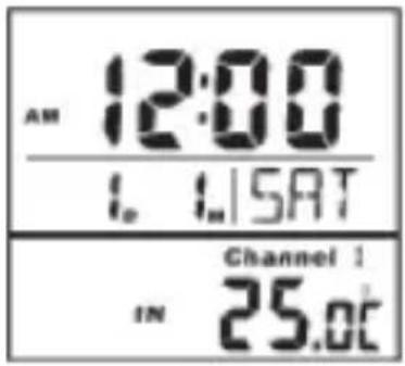
To change between indoor and outdoor temperature display, press the TEMPERATURE SELECT button.
Outdoor Temperature
The CR-A149 comes equipped with a wireless outdoor temperature sensor. The outdoor sensor will check the outdoor temperature every 6 seconds.
The outdoor temperature range is -20 – 60°C or -4 – 140°F.
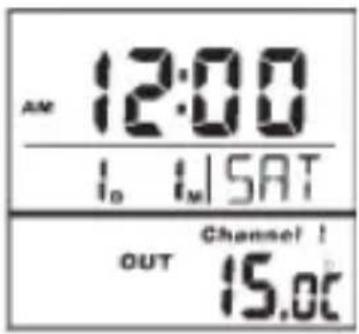
To change between indoor and outdoor temperature display, press the TEMPERATURE SELECT button.
Wireless Outdoor Temperature Sensor
The outdoor temperature sensor features an LCD display (1) and low battery level indicator (2).
The outdoor temperature sensor requires 2 x "AAA" batteries.
Remove the screws on the battery compartment (5) cover.
Set the temperature display unit switch (3) to °C or °F. The unit may also be reset at this time by pressing the reset button (4).
Load the batteries into the compartment in the orientation indicated by the diagram.
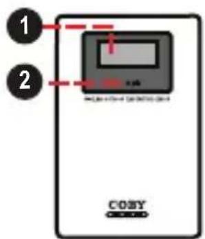
FrontRear
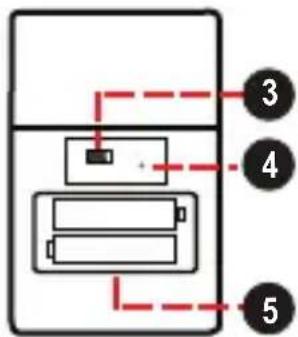
TEMPERATURE READING
For best operation:
◆ Load the batteries in the outdoor sensor before powering on the main unit.
Although the outdoor sensor is weatherproof, it should be placed in an area protected from direct sunlight, rain, and snow.
Place the main unit as close to the outdoor sensor as possible. The maximum distance between the main unit and outdoor sensor is 15 to 20 meters (50 to 65 feet).

The transmission range may be affected greatly by building materials and obstacles between the main and remote unit. Try different positions to obtain the best reception.
Low temperatures will decrease the batteries voltage and effective transmission range.
Interference from other household devices (e.g., door bells, home security systems, wireless telephone systems, and wireless network routers) may cause temporary reception failure. This will not affect the general performance of the product as transmission and reception of temperature readings will resume once the interference recedes.
PROJECTION SYSTEM
The CR-A149 contains two built-in projectors that can display the time and temperature on the ceiling or wall of a darkened room.
- Press the TEMPERATURE PROJECTION button to turn the temperature projector on or off.
◆ Press the CLOCK PROJECTION button to turn the clock projector on or off.
Turn the dials on the projection mechanism to focus the image on the ceiling or wall.

The maximum projection distance is between 3 and 9 feet.
RADIO MODE
Basic Operation
To turn the radio on, press the POWER button. (To turn the radio off, press the POWER button again.)
◆ Set the RADIO BAND switch to:
✨ AM: Listen to AM broadcasts.
✨ FM: Listen to FM broadcasts.
To adjust the volume level, turn the Volume Level dial
Tuning
✦ Turn the Radio Tuning Dial to tune to a desired broadcast station.
The current station is displayed by the Radio Tuning Indicator/Radio Frequency Band.
Reception
For FM broadcasts, extend the FM antenna fully and adjust its position for best reception (the FM wire antenna is located on the rear of the unit).
For AM broadcasts, the unit should be positioned for best signal strength (the AM antenna is built into the unit).
TROUBLESHOOTING
If you have a problem with this device, please read the troubleshooting guide below and check our website at www.cobyusa.com for Frequently Asked Questions (FAQs) and firmware updates. If these resources do not resolve the problem, please contact Technical Support.
COBY Electronics Technical Support
Address: 56-65 Rust St.
Maspeth, NY 11378
Hours: 8:30 AM–11:00 PM EST, seven days a week
Phone: 800-681-2629 or 718-416-3197
Email: techsupport@cobyusa.com
Web: www.cobyusa.com
There is no power to the device.
◆ Ensure that the power cord is securely connected to the unit and the proper wall outlet.
There is no sound.
♦ Try adjusting the volume.
◆ Ensure that nothing is connected to the AUDIO IN jack.
The sound is distorted.
The unit may be positioned too closely to a large appliance (e.g., a TV or refrigerator). If possible, turn the appliance off or move the unit to another location.
◆ Ensure that the radio is in broadcast reception range.
♦ Decrease the volume level.
SPECIFICATIONS
Power Supply AC 120V \~60Hz
5W
Battery Backup 3V Flat Lithium CR2025 x 3
Remote Sensor 1.5V "AAA" x 2
Tuning System
AM: 530 - 1710kHz
FM: 88 - 108MHz
RCC Carrier Frequency 60kHz
RCC Station WWVB
Audio Output Full-Range Speaker
Output Power 350mW
Speaker Impedance 8Ω
Specifications and manual are subject to change without notice.
NOTES
NOTES
COBY Electronics Corp.
56-65 Rust Street
Maspeth, NY 11378
www.cobyusa.com
www.ecoby.com
- Projection AM/FM Alarm Atomic Clock Radio with Temperature Display
- INSTRUCTION MANUAL
- PRECAUTIONS
- For Customer Use:
- WARNING:
- CAUTION:
- IMPORTANT SAFETY INSTRUCTIONS
- TABLE OF CONTENTS
- PRECAUTIONS 2
- IMPORTANT SAFETY INSTRUCTIONS .... 3
- TABLE OF CONTENTS ...... 6
- FEATURES 7
- GETTING STARTED 8
- CLOCK/ALARM MODE 12
- TEMPERATURE READING 16
- PROJECTION SYSTEM 18
- RADIO MODE 19
- TROUBLESHOOTING 20
- SPECIFICATIONS 21
- FEATURES
- GETTING STARTED
- CR-A149 at a Glance
- Top View
- Front View
- Rear View
- Right View
- Left View
- Power Connection
- AC Power
- Battery Backup
- Reset
- Preparing the CR-A149 for Use
- CLOCK/ALARM MODE
- Setting the Clock Time and Date
- Setting the Alarm Timer
- Turning the Alarm Timer On/Off (Alarm Mode)
- Snooze Function
- Setting the Sleep Timer
- TEMPERATURE READING
- Indoor Temperature
- Outdoor Temperature
- Wireless Outdoor Temperature Sensor
- For best operation:
- PROJECTION SYSTEM
- RADIO MODE
- Basic Operation
- Tuning
- Reception
- TROUBLESHOOTING
- COBY Electronics Technical Support
- There is no power to the device.
- There is no sound.
- The sound is distorted.
- SPECIFICATIONS
- NOTES
- COBY Electronics Corp.
Brand : COBY
Model : CR-A149
Category : Alarm clock radio