
1766 - Coffee grinder BLACK & DECKER - Free user manual and instructions
Find the device manual for free 1766 BLACK & DECKER in PDF.


| Product Type | 6-inch Bench Grinder |
| Model | 1766 |
| Brand | Black & Decker |
| Arbor Size | 1/2 inch |
| No-Load Speed | 3450 RPM |
| Power Source | 120V AC, 60 Hz |
| Wheel Diameter | 6 inches |
| Wheel Face Width | Up to 5/8 inch |
| Motor Type | B&D built motor |
| Switch Type | Rocker switch (ON/OFF) |
| Construction Material | Cast iron base and guards |
| Weight | Approximately 12 lbs (5.4 kg) |
| Dimensions (L x W x H) | 14 x 10 x 10 inches (35.6 x 25.4 x 25.4 cm) |
| Included Accessories | 2 tool rests, 2 spark guards, 2 eye shields, mounting template |
| Primary Functions | Grinding, buffing, wire brushing (with appropriate accessories) |
| Safety Features | Wheel guards, eye shields, spark guards, grounding plug |
| Mounting | Bench mount required; bolts not included |
| Maintenance | No periodic lubrication; bearings are sealed |
| Repair Parts Availability | Through Black & Decker authorized service centers |
| Warranty | 1-year free maintenance and full warranty against defects |
| Compatible Accessories (Grinding Wheels) | 6" diameter, 1/2" arbor, max safe speed 4136 RPM |
| Compatible Accessories (Buffing Wheel) | 6" diameter, 5/8" face, 3600 RPM |
| Compatible Accessories (Wire Brush) | 6" diameter, 1/2" arbor, 5/8" face, 3600 RPM |
| Extension Cord Requirement | 3-wire grounding type; gauge depends on length and amperage |
| Manual Part Number | 154408 |
Frequently Asked Questions - 1766 BLACK & DECKER
User questions about 1766 BLACK & DECKER
0 question about this device. Answer the ones you know or ask your own.
Ask a new question about this device
Download the instructions for your Coffee grinder in PDF format for free! Find your manual 1766 - BLACK & DECKER and take your electronic device back in hand. On this page are published all the documents necessary for the use of your device. 1766 by BLACK & DECKER.
USER MANUAL 1766 BLACK & DECKER
154408 manual 4/30/02 10:16 AM Page 2
Black & Decker (U.S.) Inc. • 701 East Joppa Road, Towson, Maryland 21286
Printed in U.S.A. (AUG95-1) Form No. 154408 Copyright © 1995

Instruction Manual
1766 6" Bench Grinder
1788 8" Bench Grinder
Getting the most out of your tool.
Please take time to read this manual and pay particular attention to the safety rules we've provided for your protection. If you have any questions about your tool please call:
1-800-9-BD TOOL
(1-800-923-8665)

1766 - 6" Bench Grinder 1/2" Arbor, 3450 RPM
1788 - 8" Bench Grinder 5/8" Arbor, 3600 RPM
IMPORTANT SAFETY INSTRUCTIONS
WARNING: When using electric tools, basic safety precautions should always be followed to reduce risk of fire, electric shock, and personal injury, including the following:
READ ALL INSTRUCTIONS
Grounding Instructions
This tool should be grounded while in use to protect the operator from electric shock. The tool is equipped with a 3-conductor cord and 3-prong grounding type plug to fit the proper grounding type receptacle. The green (or green and yellow) conductor in the cord is the grounding wire. Never connect the green (or green and yellow) wire to a live terminal. If your unit is intended for use on less than 150 V, it has a plug that looks like that shown in sketch A. If it is for use on 150 to 250 V, it has a plug that looks like that shown in sketch D. An adapter, sketches B and C, is available for connecting sketch A type plugs to 2-prong receptacles. The green-colored rigid ear, lug, or the like, extending from the adapter must be connected to a permanent ground, such as a properly grounded outlet box. No adapter is available for a plug as shown in sketch D. ADAPTER SHOWN IN FIGURES B and C IS NOT FOR USE IN CANADA. Use only 3-wire extension cords that have 3-prong grounding-type plugs and 3-pole receptacles that accept the tool's plug. Replace or repair damaged cords.

Safety Instructions For All Tools
- KEEP WORK AREA CLEAN. Cluttered areas and benches invite injuries.
- CONSIDER WORK AREA ENVIRONMENT. Don't expose power tools to rain. Don't use power tools in damp or wet locations. Keep work area well lit. Do not use tool in presence of flammable liquids or gases.
- GUARD AGAINST ELECTRIC SHOCK. Prevent body contact with grounded surfaces. For example: pipes, radiators, ranges, and refrigerator enclosures.
- KEEP CHILDREN AWAY. Do not let visitors contact tool or extension cord. All visitors should be kept away from work area.
- STORE IDLE TOOLS. When not in use, tools should be stored in dry, and high or locked-up place — out of reach of children.
- DON'T FORCE TOOL. It will do the job better and safer at the rate for which it was intended.
- USE RIGHT TOOL. Don't force small tool or attachment to do the job of a heavy-duty tool. Don't use tool for purpose not intended.
- DRESS PROPERLY. Do not wear loose clothing or jewelry. They can be caught in moving parts. Rubber gloves and non-skid footwear are recommended when working outdoors. Wear protective hair covering to contain long hair.
• USE SAFETY GLASSES. Also use face or dust mask if operation is dusty. - DON'T ABUSE CORD. Never carry tool by cord or yank it to disconnect from receptacle. Keep cord from heat, oil, and sharp edges.
- SECURE WORK. Use clamps or a vise to hold work. It's safer than using your hand and it frees both hands to operate tool.
- DON'T OVERREACH. Keep proper footing and balance at all times.
- MAINTAIN TOOLS WITH CARE. Keep tools sharp and clean for better and safer performance. Follow instructions for lubricating and changing accessories. Inspect tool cords periodically and if damaged, have repaired by authorized service facility. Inspect extension cords periodically and replace if damaged. Keep handles dry, clean, and free from oil and grease.
- DISCONNECT OR LOCK OFF TOOLS when not in use, before servicing, and when changing accessories, such as blades, bits, cutters.
- REMOVE ADJUSTING KEYS AND WRENCHES. Form habit of checking to see that keys and adjusting wrenches are removed from tool before turning it on.
- AVOID UNINTENTIONAL STARTING. Don't carry tool with finger on switch. Be
sure switch is off when plugging in.
- EXTENSION CORDS. Make sure your extension cord is in good condition. When using an extension cord, be sure to use one heavy enough to carry the current your product will draw. An undersized cord will cause a drop in line voltage resulting in loss of power and overheating. The following table shows the correct size to use depending on cord length and nameplate ampere rating. If in doubt, use the next heavier gage. The smaller the gage number, the heavier the cord.
Minimum Gage for Cord Sets
| Volts Total Length of Cord in Feet |
| 120V 0-25 26-50 51-100 101-150 |
| 240V 0-50 51-100 101-200 201-300 |
Ampere Rating
| More Than | Not | more | AWG | |||||||
| 0 | - | 6 | 1 | 8 | 1 | 6 | 1 | 6 | 1 | 4 |
| 6 | - | 1 | 0 | 18 | 16 | 14 | 12 | |||
| 10 | - | 12 | 16 | 16 | 14 | 12 | ||||
| 12 | - | 16 | 14 | 12 | Not Recommended |
- OUTDOOR USE EXTENSION CORDS. When tool is used outdoors, use only extension cords intended for use outdoors and so marked.
- STAY ALERT. Watch what you are doing. Use common sense. Do not operate tool when you are tired.
- CHECK DAMAGED PARTS. Before further use of the tool, a guard or other part that is damaged should be carefully checked to determine that it will operate properly and perform its intended function. Check for alignment of moving parts, binding of moving parts, breakage of parts, mounting, and any other conditions that may affect its operation. A guard or other part that is damaged should be properly repaired or replaced by an authorized service center unless otherwise indicated elsewhere in this instruction manual. Have defective switches replaced by authorized service center. Do not use tool if switch does not turn it on and off.
SAVE THESE INSTRUCTIONS
Additional Safety Instructions for Grinders
- Always use guards and eye shields. Always wear safety glasses or other eye protection when operating this tool and keep the eye shields mounted in their proper position on the wheel guard.
- Replace a cracked wheel immediately. Handle grinding wheels carefully to avoid bumping or dropping. DO NOT use a grinding wheel that has been dropped. Before using, inspect recommended accessory for cracks or flaws. If such a crack or flaw is evident, discard the accessory. The accessory should also be inspected whenever you think the tool may have been dropped.
- Before mounting a new wheel, be sure that it is marked with an RPM that is the same as, or higher than, the no-load speed of the grinder as marked on the nameplate. Keep tool rests and spark shields adjusted.
- Never start a grinder with anyone, including the operator, standing in line with the wheel. After installing a replacement wheel, stand to one side and allow it to revolve freely for about one minute.
- Do not grind on the sides of grinding wheels unless they are the special wheels designed specifically for this purpose.
- Do not overtighten wheel nut.
- Use only clamp washer furnished with this grinder.
- Bolt bench grinder to a bench or pedestal to prevent movement. SEE PAGE 5 FOR BENCH MOUNTING INSTRUCTIONS.
- Use accessories only in the proper and intended manner.
SAVE THESE INSTRUCTIONS
Motor
Your B&D tool is powered by a B&D built motor. Be sure your power supply agrees with the nameplate marking. Voltage decrease of more than 10% will cause loss of power and overheating. All B&D tools are factory tested; if this tool does not operate, check the power supply.
Switch
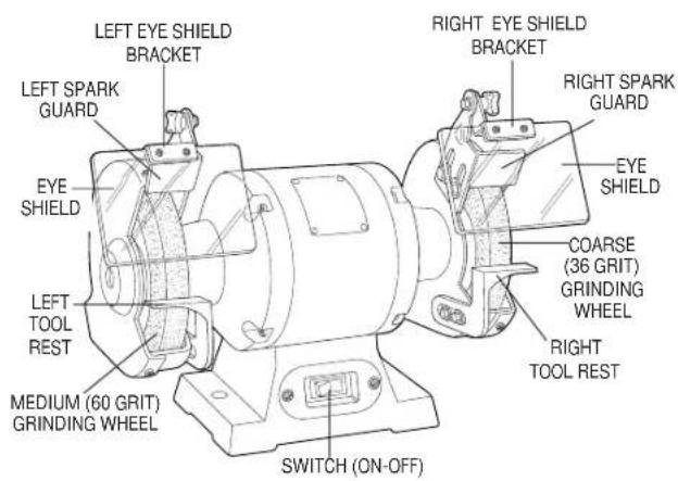
The switch is located on the front of the grinder near the bottom. To turn the tool on, depress the rocker switch near the word "ON". To turn the tool off, depress the rocker switch near the word "OFF".
Installing Tool Rests
TURN OFF TOOL AND DISCONNECT FROM POWER SUPPLY.
Remove the tool rests from the top portion of the poly-foam carton liner and install them to the wheel guards as shown in Figures 1A (1766) and 1B (1788). Use the bolts and washers from the plastic bag to secure them in place.
NOTE: There is a left and a right tool rest. When in actual use, the tool rests should be adjusted to within 1/8" of the grinding wheel or other accessory being used.
Installing Spark Guards and Eye Shield Brackets
TURN OFF TOOL AND DISCONNECT FROM POWER SUPPLY.
The combination spark guard and eye shield brackets are assembled and in a plastic bag. They are identified L for left and R for right. Refer to Figure 2 to install them to the bench grinder using the two screws in the wheel guard (in some cases these screws will be in the plastic bag). Adjust the edge of the spark guard to within 1/16" of the grinding wheel or other accessory as shown in the Figure. Tighten the two screws securely.
FIGURE 1A - 1766

FIGURE 1B - 1788


Installing Eye Shields
TURN OFF TOOL AND DISCONNECT FROM POWER SUPPLY.
Remove the steel strip from the top surface of each eye shield by removing the two screws. Install the shields, (they are identical and will fit either side) to the brackets, as shown in Figure 3. Tighten screws securely. Adjust eye shields so they are between the wheels and your eyes.
EYE SHIELDS ARE NOT DESIGNED TO REPLACE SAFETY GLASSES.
Tighten the shields in place by tightening the plastic knob in the bracket assembly. Remove protective paper cover.
Operating Instructions
To operate the grinder, put on safety glasses and turn the tool on. Allow it to reach full speed (3600 RPM for 1788, 3450 RPM for 1766) before grinding. Hold the workpiece firmly and against the tool rest. Hold very small pieces with pliers or other suitable clamps. Feed the work smoothly and evenly into the grinding wheel. Move the work slowly and avoid jamming the work against the wheel. As the wheel tends to slow down you should occasionally release the pressure to let the wheel return to full speed.
Grind only on face of the grinding wheel and never the side of it. (Some wheels are designed for side grinding and will say so on their blotters.)
CAUTION: Prolonged grinding will cause most materials to become hot. Use care when handling them.
Lubrication
Bench grinder spindles are mounted on ball bearings. No periodic lubrication is required.

IMPORTANT!
To assure product safety and reliability, particularly for double insulated tools, repairs, maintenance and adjustment (excluding maintenance described in this manual) should be performed by B&D service centers or authorized service centers, using identical B&D replacement parts.
Bench Mounting
TURN OFF TOOL AND DISCONNECT FROM POWER SUPPLY.
Mounting the grinder securely to a bench is strongly recommended in order
6"
to prevent movement of the grinder when pressure is applied against a grinding wheel. To mount your bench grinder, follow the steps below:
-
Cut out the template on the dotted line and tape it down to your workbench where you want to mount the tool. Don't forget about the availability of an electric socket. The word "FRONT" indicates the position of the front of the grinder.
-
Using a centerpunch, mark the centers of the two holes shown in the template.
-
Remove the template and drill the appropriate size holes in the places you marked. a. If fastening to a metal surface drill 1/4" holes and use 1/4" hex head machine screws and nuts.
b. If fastening to a wood surface drill pilot holes and use 1/4" hex head wood screws. (Hardware not included).
-
Be sure to use screws with heads large enough so that they don't go completely through the base of the grinder. If needed, flat washers can be used to correct such a problem.
-
When tightening down on the screws, be careful to avoid compressing the rubber feet too much. If they are over compressed they will not be able to do their job of absorbing vibration.
NEVER ATTEMPT TO USE YOUR BENCH GRINDER UNLESS IT IS FIRMLY BOLTED TO A WORKBENCH OR OTHER RIGID FRAME.
Changing Accessories
TURN OFF TOOL AND DISCONNECT FROM POWER SUPPLY.
CHANGE ACCESSORIES WHEN THE SPARK GUARD CAN NO LONGER BE ADJUSTED TO 1/16" FROM THE
FRONT
WHEEL.
(For 1766: USE ONLY WHEELS THAT MEASURE 6" IN DIAMETER. THIS TOOL HAS 1/2" ARBORS ON BOTH SIDES)
(For 1788: USE ONLY WHEELS THAT MEASURE 8" IN DIAMETER. THIS TOOL HAS 5/8" ARBORS ON BOTH SIDES.)
Follow the steps below to remove the replace an accessory.
- Raise the eye shield up, out of the way.
- Loosen and pull the tool rest out as far as possible. Do not remove it.
- Loosen and pull the spark guard out as far as possible. Do not remove it.
-
Remove the screws from the wheel cover and remove cover.
-
Using hex or adjustable wrenches of the appropriate sizes, grasp the two hex nuts holding the wheels to the arbor shaft at each end of the tool. To remove the wheel from the right side of the tool, turn the right side hex nut counterclockwise, while holding the left side hex nut stationary. To remove the wheel from the left, turn the left side hex nut clockwise while holding the right side hex nut stationary.
-
Remove the wheel washer and the wheel.
-
Inspect the wheel for cracks, chips or any other visible damage (other than normal wear) and discard if such damage is found. Inspect the blotter for damage. If the blotter is missing or severely damaged, replace it with a piece of thin cardboard or blotter paper cut in the same shape. NEVER USE A WHEEL WITHOUT A BLOTTER.
-
Install the new wheel or other accessory. Be sure that both wheel washers are in place (concave sides toward wheel). See Figure 4. (for 1766 see Figures 4 and 5).
-
Hold as before and tighten the nut firmly but do not overtighten. Overtightening can crack a grinding wheel.
-
Replace the wheel cover and its screws.
-
Adjust the spark guard to 1/16" from the wheel and tighten it securely.
- Adjust the tool rest to 1/8" from the wheel and tighten securely.
- Adjust the eye shield to a point between your eyes and the wheel. The bench grinder is now ready to use.
- Follow the above steps to install buffing wheels and wire wheel brushes as well as grinding wheels.
Accessories
Recommended accessories for use with your tool are available at extra cost


from your distributor or local service center.
CAUTION: The use of any non-recommended accessory may be hazardous.
If you need assistance in locating any accessory call 1-800-9-BD TOOL: (1-800-923-8665) or contact Black & Decker (U.S.) Inc., Consumer Services Department, 626 Hanover Pike, P.O. Box 618, Hampstead, MD 21074.
1766
GRINDING WHEELS MAX. SAFE SPEED
5/8" Face, 6" dia. 60 grit medium grinding wheel 4136 RPM
3/4" Face, 6" dia. 60 grit medium grinding wheel 4136 RPM
5.8" Face, 6" dia. 36 grit coarse grinding wheel 4136 RPM
1/2" Face, 6" dia. 60 grit medium grinding wheel 3825 RPM
BUFFING WHEELS
5/8" Face, 6" dia. cotton buffing wheel 3600 RPM
WIRE WHEEL BRUSHES
1/2" arbor, 5/8" Face, 6" dia. 3600 RPM
1788
GRINDING WHEELS MAX. SAFE SPEED
7/8" & 1" Face, 8" dia. 60 grit medium grinding wheel 3600 RPM
7/8" & 1" Face, 8" dia. 36 grit coarse grinding wheel 3600 RPM
BUFFING WHEEL
5/8" arbor, 8" dia. cotton buffing wheel 3600 RPM
WIRE WHEEL BRUSHES
5/8" arbor, 5/8"-1 1/4" Face, 8" dia. 3600 RPM
Every B&D tool is of the highest quality.
If you wish to contact us regarding this product, please call toll free between 8:00am and 8:00pm ET, seven days a week:
1-800-9-BD TOOL
(1-800-923-8665)
One Year Free Maintenance
All B&D tools for Industry and Construction are covered under a one year free maintenance program where B&D will inspect your tool for safety and provide necessary maintenance or repairs, including normal wear and tear parts, for one year, FREE OF CHARGE.
Full Warranty
All B&D tools for Industry and Construction are warranted to be free of any defects in materials or workmanship. Upon thorough examination of tool, B&D will repair or replace, at our option, any product that is determined to be defective.
Conditions
The service/safety check and the warranty do not apply to: repairs made or attempted by anyone other than an authorized B&D service location; misuse, abuse, neglect, improper application of the tool; missing parts; or normal wear and tear (after first year of ownership). Please return the complete unit, transportation prepaid, to any B&D factory owned or B&D authorized service center location (list provided with tool or see Yellow Pages under "Tools Electric").
- Instruction Manual
- Getting the most out of your tool.
- IMPORTANT SAFETY INSTRUCTIONS
- READ ALL INSTRUCTIONS
- Grounding Instructions
- Safety Instructions For All Tools
- SAVE THESE INSTRUCTIONS
- Additional Safety Instructions for Grinders
- Motor
- Switch
- Installing Tool Rests
- Installing Spark Guards and Eye Shield Brackets
- Installing Eye Shields
- Operating Instructions
- Lubrication
- IMPORTANT!
- Bench Mounting
- 6"
- Changing Accessories
- FRONT
- WHEEL.
- Accessories
- One Year Free Maintenance
- Full Warranty
- Conditions
Brand : BLACK & DECKER
Model : 1766
Category : Coffee grinder