
P2RL-SP - Alarm system System Sensor - Free user manual and instructions
Find the device manual for free P2RL-SP System Sensor in PDF.


| Type | 2-Wire Wall Mount Selectable Output Horn Strobe |
| Dimensions (Standard) | Length: 5.6 in (143 mm), Width: 4.7 in (119 mm), Depth: 1.25 in (32 mm) |
| Operating Voltage Range | 8-17.5 V (12 V nominal) or 16-33 V (24 V nominal / FWR) |
| Strobe Flash Rate | 1 flash per second |
| Candela Settings (Wall) | 15, 30, 75, 95, 110, 135, 185 cd |
| Horn Tones | 8 field-selectable: Temporal, Non-Temporal, 3.1 kHz Temporal, 3.1 kHz Non-Temporal, each with High/Low volume |
| Operating Temperature | 32 °F to 120 °F (0 °C to 49 °C) |
| Humidity Range | 10% to 93% non-condensing |
| Wire Gauge | 12 to 18 AWG |
| Mounting Compatibility | 4 in x 4 in x 1.5 in, Single Gang, Double Gang, 4 in Octagon; optional Surface Mount Back Box (SBBRL/WL) |
| Synchronization | Built-in System Sensor synchronization protocol; compatible with MDL3 Sync Module or FACP with System Sensor protocol |
| Special Features | Shorting spring for continuity check, tamper-resistant Torx screw, backward compatible with previous generation |
| Warranty | 3-year limited warranty |
| Standards | ANSI/UL 464 (public mode horn), ANSI/UL 1638 (public mode strobe), NFPA 72 compliant |
| FCC Compliance | Class B digital device, Part 15 |
Frequently Asked Questions - P2RL-SP System Sensor
User questions about P2RL-SP System Sensor
0 question about this device. Answer the ones you know or ask your own.
Ask a new question about this device
Download the instructions for your Alarm system in PDF format for free! Find your manual P2RL-SP - System Sensor and take your electronic device back in hand. On this page are published all the documents necessary for the use of your device. P2RL-SP by System Sensor.
USER MANUAL P2RL-SP System Sensor
Selectable Output Horn Strobes, Chime Strobes and Strobes – Wall Mount
For use with the following models:
Standard Wall Mount Horn Strobes: P2RL, P2WL, P2RL-P, P2WL-P, P2RL-SP, P2WL-SP
Compact Wall Mount Horn Strobes: P2GRL, P2GWL
Standard Wall Mount Chime Strobes: CHSRL, CHSWL
Standard Wall Mount Strobes: SRL, SWL, SRL-P, SWL-P, SRL-SP, SWL-CLR-ALERT
Compact Wall Mount Strobes: SGRL, SGWL
PRODUCT SPECIFICATIONS
Standard Operating Temperature: 32°F to 120°F (0°C to 49°C)
Humidity Range: 10 to 93% Non-condensing
Strobe Flash Rate 1 flash per second
Nominal Voltage: Regulated 12VDC or regulated 24DC/FWR
Operating Voltage Range: 8 to 17.5V (12V nominal) or 16 to 33V (24V nominal)
Operating Voltage with MDL3 Sync Module: 8.5 to 17.5V (12V nominal) or 16.5 to 33V (24V nominal)
Input terminal wire gauge: 12 to 18 AWG
DIMENSIONS FOR PRODUCTS AND ACCESSORIES
| WALL PRODUCTS Length | Width | Depth | |
| Standard Strobe, Chime Strobe and Horn Strobe | 5.6" (143mm) | 4.7" (119mm) | 1.25" (32mm) |
| Compact Strobe and Horn Strobe | 5.26" (133 mm) | 3.46" (88 mm) | 1.93 (49 mm) |
| Standard device with SBBRL/WL Surface Mount Back Box | 5.9" (149 mm) | 4.9" (125 mm) | 1.85" (47 mm) |
| Compact device with SBBGRL/WL Surface Mount Back Box | 5.5" (140 mm) | 3.7" (94 mm) | 1.6" (39 mm) |
| NOTE: SBBRL/WL Surface Mount Back Box intended only for standard horn strobes, chime strobes and strobes.SBBGRL/WL Surface Mount Back Box intended for compact horn strobes and strobes. | |||
MOUNTING BOX OPTIONS
Standard 2-Wire Indoor Products:
4" x 4" x 1½", Single Gang, Double Gang, 4" Octagon, SBBRL/WL (wall), SBBGRL/WL (wall)
Compact 2-Wire Indoor Products:
Single Gang, SBBGRL/WL (wall)
NOTICE: This manual shall be left with the owner/user of this equipment.
BEFORE INSTALLING
Please read the System Sensor Audible Visible Application Reference Guide, which provides detailed information on notification devices, wiring and special applications. Copies of this manual are available from System Sensor. NFPA 72 and NEMA guidelines should be observed.
Important: The notification appliance used must be tested and maintained following NFPA 72 requirements.
GENERAL DESCRIPTION
System Sensor series of notification appliances offer a wide range of audible and visible devices for life safety notification. Our 2-wire horn strobes, chime strobes and strobes come with 8 field selectable tone and volume combinations and 7 field selectable candela settings. Intended for indoor applications and approved for wall mount installations only. Available in two attractive mounting designs, standard and compact (horn strobe and strobe only).
2-wire horn strobes and strobes are public mode notification appliances intended to alert occupants of a life safety event. The 2-wire chime strobe is a private mode notification appliance. The horn is listed to ANSI/UL 464 requirements (public mode) and the strobe is listed to ANSI/UL 1638 (public mode). 2-wire chime strobe is a private mode notification appliances intended to alert trained personnel to investigate a life safety event and take appropriate actions. The chime portion of the chime strobe is listed to ANSI/UL 464 (private mode) and the strobe portion is listed to ANSI/UL 1638 (private mode).
System Sensor notification appliances are designed to be used in either 12 VDC, 24VDC, or 24V FWR (full wave rectified) systems. System Sensor AV devices can be activated by a compatible fire alarm control panel or power supply. Refer to the appropriate fire alarm control panel manufacturer or power supply for more information.
System Sensor wall 2-wire horn strobes, 2-wire chime strobes, and strobes are electrically backward compatible with the previous generation, since 1996, of notification appliances. They come enabled with System Sensor synchronization protocol which requires connections to a power supply capable of generating the System Sensor synchronization pulses, a FACP NAC output configured to System Sensor synchronization protocol, or the use of MDL3 module to generate the synchronization protocol.
FIRE ALARM SYSTEM CONSIDERATIONS
The National Fire Alarm and Signaling Code, NFPA 72, requires that all notification appliances, used for building evacuation installed after July 1, 1996, produce temporal coded signals. Signals other than those used for evacuation purposes do not have to produce the temporal coded signal. System Sensor recommends spacing notification appliances in compliance with NFPA 72.
SYSTEM DESIGN
The system designer must make sure that the total current draw by the devices on the loop does not exceed the current capability of the panel supply, and that the last device on the circuit is operated within its rated voltage. The current draw information for making these calculations can be found in the tables within the manual. For convenience and accuracy, use the voltage drop calculator on the System Sensor website (www.systemsensor.com).
When calculating the voltage available to the last device, it is necessary to consider the voltage due to the resistance of the wire. The thicker the wire, the smaller the voltage drop. Wire resistance tables can be obtained from electrical handbooks. Note that if Class A wiring is installed, the wire length may be up to twice as long as it would be for circuits that are not fault tolerant. The total number of strobes on a single NAC must not exceed 69 for 24 volt applications.
AVAILABLE TONES
System Sensor offers a wide variety of tones for your life safety needs, including temporal 3 pattern ( 1/2 second on, 1/2 second off, 1/2 second on, 1/2 second off, 1/2 second on, 11/2 off and repeat) which is specified by ANSI and NFPA 72 for standard emergency evacuation signaling.
To select the tone, turn the rotary switch on the back of the product to the desired setting. (See Figure 1.)
Available horn settings can be found in Table 1. Available chime settings can be found in Table 2.
TABLE 1. HORN TONES
| Pos | Tone | Volume Setting |
| 1 | Temporal | High |
| 2 | Temporal | Low |
| 3 | Non-Temporal | High |
| 4 | Non-Temporal | Low |
| 5 | 3.1 KHz Temporal | High |
| 6 | 3.1 KHz Temporal | Low |
| 7 | 3.1 KHz Non-Temporal | High |
| 8 | 3.1 KHz Non-Temporal | Low |
TABLE 2. CHIME TONES
| Pos | Tone | Volume Setting |
| 1 | 1 Second Chime | High |
| 2 | 1 Second Chime | Low |
| 3 | 1/4 Second Chime | High |
| 4 | 1/4 Second Chime | Low |
| 5 | Temporal Chime | High |
| 6 | Temporal Chime | Low |
| 7 | 5 Second Whoop | High |
| 8 | 5 Second Whoop | Low |
AVAILABLE CANDELA SETTINGS
System Sensor offers a wide range of candela settings for your life safety needs. In order to select your candela output, adjust the slide switch on the rear of the product to the desired candela setting on the selector switch. (See Figure 2.)
The candela setting can also be verified by looking into the small window on the front of the unit. See Table 3 for candela settings for wall products. All products meet the light output profiles specified in the appropriate UI. Standards. (See Figures 3 and 4.)
CURRENT DRAW AND AUDIBILITY RATINGS
For the strobe, the current draw for each setting is listed in Table 3. For the horn strobe, the current draw and audibility settings are listed in Table 4. For the chime strobe, the current draw and audibility settings are listed in Table 5.
FIGURE 1. AUDIO SELECTOR

AUDIO SELECT
FIGURE 2. CANDELA SELECTOR

A0486-00
TABLE 3. WALL-MOUNT STROBE CURRENT DRAW (mA)
| Candela | 8-17.5 Volts | 16-33 Volts | |
| DC DC FWR | |||
| 15 | 88 | 43 | 60 |
| 30 | 143 | 63 | 83 |
| 75 - | 107 | 136 | |
| 95 - | 121 | 155 | |
| 110 | - | 148 | 179 |
| 135 | - | 172 | 209 |
| 185 | - | 222 | 257 |
NOTE: Products set at 15 and 30 candela automatically work on either 12V or 24V power supplies. The products are not listed for 12V DC operation when set to any other candela settings.
FIGURE 3. LIGHT OUTPUT - FIGURE 4. VERTICAL
HORIZONTAL DISPERSION DISPERSION- WALL TO FLOOR
| Degrees* | Percent of Rating |
| 0 100 0 100 | |
| 5-25 90 5-30 90 | |
| 30-45 75 35 65 | |
| 50 55 40 46 | |
| 55 | 45 45 34 |
| 60 | 40 50 27 |
| 65 | 35 55 22 |
| 70 35 60 18 | |
| 75 | 30 |
| 80 | 30 |
| 85 | 25 75 13 |
| 90 | 25 80 12 |
| Compound 45 to the left | 24 85 12 |
| Compound 45 to the right | 24 90 12 |
| Degrees* | Percent of Rating |
| 65 16 | |
| 70 | 15 |
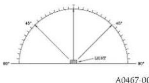

* Tolerance of ±1 degree is permitted.
WIRING AND MOUNTING
All wiring must be installed in compliance with the National Electric Code and the local codes as well as the authority having jurisdiction. Wiring must not be of such length or wire size which would cause the notification appliance to operate outside of its published specifications. Improper connections can prevent the system from alerting occupants in the event of an emergency. Wire sizes up to 12 AWG (2.5 mm°) may be used with the mounting plate. The mounting plate ships with the terminals set for 12 AWG wiring.
Make wire connections by stripping about 3/8 " of insulation from the end of the wire. Then slide the bare end of the wire under the appropriate clamping plate and tighten the clamping plate screw.
We provide a wire strip guide. See Figure 5 for wiring terminals and strip guide reference.
CAUTION
Factory finish should not be altered: Do not paint!
CAUTION
Do not over tighten mounting plate screws; this may cause mounting plate to flex.
FIGURE 5. WIRING TERMINALS, SHORTING SPRING, AND STRIP GUIDE

A0475-01
SYSTEM WIRING
The 2-wire horn strobe, chime strobe and strobe only require two wires for power and supervision. (See Figure 6.) Please consult your FACP manufacturer or power supply manufacturer for specific wiring configurations and special cases.
FIGURE 6.2-WIRE CIRCUIT

A0367-02
SHORTING SPRING FEATURE
System Sensor notification appliances come with a shorting spring that is provided between terminals 2 and 3 of the mounting plate to enable system continuity checks after the system has been wired, but prior to installation of the final product. (See Figure 5.) This spring will automatically disengage when the product is installed, to enable supervision of the final system.
MOUNTING
-
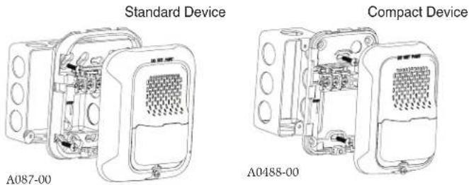
Attach mounting plate to junction box. The standard mounting plate is compatible with 4" square, single gang, double gang, and 4" octagon junction boxes. The compact mounting plate is compatible with single gang junction boxes. (See Figures 7 and 8, respectively.)
-
Connect field wiring according to terminal designations. (See Figures 5 and 6.)
-
If the product is not to be installed at this point, use the protective dust cover to prevent contamination of the wiring terminals on the mounting plate.
-
To attach product to mounting plate, hook tabs on the top of the product housing into the grooves on mounting plate. Then, hinge the product into
FIGURES 7 AND 8. MOUNTING
FIGURES 9 AND 10. SURFACE MOUNT BACK BOX MOUNTING:

TABLE 4. WALL-MOUNT HORN STROBE CURRENT DRAW (mA) AND SOUND OUTPUT (dBA)
| Current draw (mA) | Sound Output (dBA) | ||||||||||||||||||||
| Pos | Tone | Volume Setting | 8-17.5 VDC | 16-33 VDC 16-33 FWR | 8-17.5 V | 16-33 V | |||||||||||||||
| 15 | 30 | 15 | 30 | 75 | 95 | 110 | 135 | 185 | 15 | 30 | 75 | 95 | 110 | 135 | 185 | DC DC | FWR | ||||
| 1 | Temporal | High | 98 | 158 | 54 | 74 | 121 | 142 | 162 | 196 | 245 | 83 | 107 | 156 | 177 | 198 | 234 | 287 | 84 | 89 | 89 |
| 2 | Temporal | Low | 93 | 154 | 44 | 65 | 111 | 133 | 157 | 184 | 235 | 68 | 91 | 145 | 165 | 185 | 223 | 271 | 75 | 83 | 83 |
| 3 | Non-Temporal | High | 106 | 166 | 73 | 94 | 139 | 160 | 182 | 211 | 262 | 111 | 135 | 185 | 207 | 230 | 264 | 316 | 85 | 90 | 90 |
| 4 | Non-Temporal | Low | 93 | 156 | 51 | 71 | 119 | 139 | 162 | 190 | 239 | 79 | 104 | 157 | 175 | 197 | 235 | 283 | 76 | 84 | 84 |
| 5 | 3.1 KHz Temporal | High | 93 | 156 | 53 | 73 | 119 | 140 | 164 | 190 | 242 | 81 | 105 | 155 | 177 | 196 | 234 | 284 | 83 | 88 | 88 |
| 6 | 3.1 KHz Temporal | Low | 91 | 154 | 45 | 66 | 112 | 133 | 160 | 185 | 235 | 68 | 90 | 145 | 166 | 186 | 222 | 276 | 76 | 82 | 82 |
| 7 | 3.1 KHz Non-Temporal | High | 99 | 162 | 69 | 90 | 135 | 157 | 175 | 208 | 261 | 104 | 131 | 177 | 204 | 230 | 264 | 326 | 84 | 89 | 89 |
| 8 | 3.1 KHz Non-Temporal | Low | 93 | 156 | 52 | 72 | 119 | 138 | 162 | 192 | 242 | 77 | 102 | 156 | 177 | 199 | 234 | 291 | 77 | 83 | 83 |
NOTE: Products set at 15 and 30 candela automatically work on either 12V or 24V power supplies. The products are not listed for 12VDC operation when set to any other candela settings.
TABLE 5. WALL MOUNT CHIME STROBE CURRENT DRAW (mA) AND SOUND OUTPUT (dBA)
| Current draw (mA) | Sound Output (dBA) | ||||||||||||||||||||
| Pos | Chime Tone | Volume Setting | 8-17.5 VDC | 16-33 VDC 16-33 FWR | 8-17.5 V | 16-33 V | |||||||||||||||
| 15 | 30 | 15 | 30 | 75 | 95 | 110 | 135 | 185 | 15 | 30 | 75 | 95 | 110 | 135 | 185 | DC DC | FWR | ||||
| 1 | 1 Second | High | 90 | 154 | 51 | 71 | 116 | 136 | 161 | 202 | 242 | 70 | 90 | 160 | 176 | 197 | 233 | 275 | 61 | 62 | 62 |
| 2 | 1 Second | Low | 89 | 154 | 50 | 70 | 115 | 136 | 154 | 199 | 238 | 67 | 88 | 158 | 175 | 191 | 232 | 271 | 56 | 55 | 55 |
| 3 | 1/4 Second | High | 90 | 154 | 52 | 72 | 117 | 137 | 168 | 201 | 242 | 69 | 93 | 159 | 175 | 198 | 233 | 272 | 67 | 70 | 70 |
| 4 | 1/4 Second | Low | 89 | 153 | 49 | 70 | 115 | 136 | 165 | 199 | 241 | 68 | 93 | 154 | 169 | 196 | 232 | 270 | 61 | 61 | 61 |
| 5 | Temporal | High | 88 | 153 | 49 | 69 | 112 | 137 | 168 | 201 | 246 | 65 | 90 | 145 | 170 | 189 | 228 | 283 | 64 | 66 | 66 |
| 6 | Temporal | Low | 88 | 152 | 47 | 68 | 111 | 136 | 167 | 196 | 241 | 64 | 89 | 142 | 170 | 188 | 219 | 282 | 59 | 60 | 60 |
| 7 | 5 Second Whoop | High | 91 | 154 | 52 | 70 | 113 | 132 | 176 | 206 | 243 | 70 | 93 | 145 | 168 | 187 | 223 | 278 | 76 | 78 | 78 |
| 8 | 5 Second Whoop | Low | 87 | 149 | 46 | 66 | 108 | 130 | 170 | 202 | 240 | 62 | 84 | 137 | 159 | 180 | 216 | 272 | 62 | 64 | 64 |
NOTE: Products set at 15 and 30 candela automatically work on either 12V or 24V power supplies. The products are not listed for 12VDC operation when set to any other candela settings.
position to engage the pins on the product with the terminals on the mounting plate. Make sure that the tabs on the back of the product housing fully engage with the mounting plate.
- Secure product by tightening the single mounting screw in the front of the product housing.
SURFACE MOUNT BACK BOX MOUNTING
- The surface mount back box may be secured directly to the wall or ceiling. A grounding bracket with ground screw capability is provided if needed. For standard size devices see Figure 9, and for compact devices see Figure 10.
- The wall mount back box must be mounted with the up arrow pointing up. (See Figure 12.)
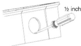
- Threaded knockout holes are provided for the sides of the box for 1/2 inch conduit adapter. Knockout holes in the back of the box can be used for 1/2 inch rear entry.
- To remove the 1/2 inch knockout, we recommend you use a flat head screw driver, place the blade of the flat head screwdriver in the inner edge of the knockout. Strike the screwdriver as you work your way around as shown in Figure 13.
NOTE: For 1/2 in. installation, use caution not to strike the knockout near the top edge of the surface mount back box.
- V500 and V700 raceway knockouts are also provided. Use V500 for low profile applications and V700 for high profile applications.
- To remove the knockout turn pliers up, as shown in Figure 13.
TAMPER SCREW
For tamper resistance, the standard captive screw may be replaced with the enclosed Torx screw.
- To remove the captive screw, back out the screw and apply pressure to the back of the screw until it disengages from the housing. Replace with the supplied Torx screw. (See Figure 11.)
FIGURE 11. TAMPER SCREW

A0478-00
FIGURE 12. SMBB UP ARROW
A0481-00

FIGURE 13. KNOCKOUT AND V500/V700 REMOVAL FOR SURFACE MOUNT BACK BOX
A0482-00

Please refer to insert for the Limitations of Fire Alarm Systems
WARNING
THE LIMITATIONS OF HORN/STROBES
The horn and/or strobe will not work without power. The horn/strobe gets its power from the fire/security panel monitoring the alarm system. If power is cut off for any reason, the horn/strobe will not provide the desired audio or visual warning.
The horn may not be heard. The loudness of the horn meets (or exceeds) current Underwriters Laboratories' standards. However, the horn may not alert a sound sleeper or one who has recently used drugs or has been drinking alcoholic beverages. The horn may not be heard if it is placed on a different floor from the person in hazard or if placed too far away to be heard over the ambient noise such as traffic, air conditioners, machinery or music appliances that may prevent alert persons from hearing the alarm. The horn may not be heard by persons who are hearing impaired.
NOTE: Strobes must be powered continuously for horn operation.
The signal strobe may not be seen. The electronic visual warning signal uses an extremely reliable xenon flash tube. It flashes at least once every second. The strobe must not be installed in direct sunlight or areas of high light intensity (over 60 foot candles) where the visual flash might be disregarded or not seen. The strobe may not be seen by the visually impaired.
The signal strobe may cause seizures. Individuals who have positive photoic response to visual stimuli with seizures, such as persons with epilepsy, should avoid prolonged exposure to environments in which strobe signals, including this strobe, are activated.
The signal strobe cannot operate from coded power supplies. Coded power supplies produce interrupted power. The strobe must have an uninterrupted source of power in order to operate correctly. System Sensor recommends that the horn and signal strobe always be used in combination so that the risks from any of the above limitations are minimized.
THREE-YEAR LIMITED WARRANTY
System Sensor warrants its enclosed product to be free from defects in materials and workmanship under normal use and service for a period of three years from date of manufacture. System Sensor makes no other express warranty for this product. No agent, representative, dealer, or employee of the Company has the authority to increase or alter the obligations or limitations of this Warranty. The Company's obligation of this Warranty shall be limited to the replacement of any part of the product which is found to be defective in materials or workmanship under normal use and service during the three year period commencing with the date of manufacture. After phoning System Sensor's toll free number 800-SENSOR2 (736-7672) for a Return Authorization number, send defective units postage prepaid to: Honeywell, 12220 Rojas Drive, Suite 700, El Paso TX 79936.
Please include a note describing the malfunction and suspected cause of failure. The Company shall not be obligated to replace units which are found to be defective because of damage, unreasonable use, modifications, or alterations occurring after the date of manufacture. In no case shall the Company be liable for any consequential or incidental damages for breach of this or any other Warranty, expressed or implied whatsoever, even if the loss or damage is caused by the Company's negligence or fault. Some states do not allow the exclusion or limitation of incidental or consequential damages, so the above limitation or exclusion may not apply to you. This Warranty gives you specific legal rights, and you may also have other rights which vary from state to state.
FCC STATEMENT
System Sensor Strobes and Horn/Strobes have been tested and found to comply with the limits for a Class B digital device, pursuant to part 15 of the FCC Rules. These limits are designed to provide reasonable protection against harmful interference when the equipment is operated in a commercial environment. This equipment generates, uses, and
can radiate radio frequency energy and, if not installed and used in accordance with the instruction manual, may cause harmful interference to radio communications. Operation of this equipment in a residential area is likely to cause harmful interference in which case the user will be required to correct the interference at his own expense.
System Sensor ® is a registered trademark of Honeywell International, Inc.

- SELECTABLE OUTPUT HORN STROBES, CHIME STROBES AND STROBES – WALL MOUNT
- PRODUCT SPECIFICATIONS
- MOUNTING BOX OPTIONS
- BEFORE INSTALLING
- GENERAL DESCRIPTION
- FIRE ALARM SYSTEM CONSIDERATIONS
- SYSTEM DESIGN
- AVAILABLE TONES
- AVAILABLE CANDELA SETTINGS
- CURRENT DRAW AND AUDIBILITY RATINGS
- WIRING AND MOUNTING
- CAUTION
- SYSTEM WIRING
- SHORTING SPRING FEATURE
- MOUNTING
- SURFACE MOUNT BACK BOX MOUNTING
- TAMPER SCREW
- PLEASE REFER TO INSERT FOR THE LIMITATIONS OF FIRE ALARM SYSTEMS
- WARNING
- THE LIMITATIONS OF HORN/STROBES
- THREE-YEAR LIMITED WARRANTY
- FCC STATEMENT
Brand : System Sensor
Model : P2RL-SP
Category : Alarm system