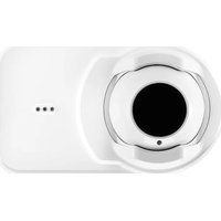
OSI-R-SS - Smoke detector System Sensor - Free user manual and instructions
Find the device manual for free OSI-R-SS System Sensor in PDF.


| Product Type | Photoelectric Smoke Detector |
| Model | OSI-R-SS |
| Brand | System Sensor |
| Dimensions | 4.1 in (104 mm) diameter, 2.1 in (53 mm) height |
| Weight | 0.3 lb (136 g) |
| Power Supply | 12-24 VDC, 100 mA max |
| Operating Temperature | 32°F to 120°F (0°C to 49°C) |
| Humidity Range | 0% to 93% non-condensing |
| Detection Method | Photoelectric (scattered light) |
| Alarm Output | Form C relay, 2 A at 30 VDC |
| Remote Output | Optional remote indicator (RA-400Z) |
| Main Functions | Smoke detection, local alarm, remote signaling, drift compensation |
| Maintenance | Clean dust from vents annually; test monthly |
| Safety Certifications | UL 268, FM, CSFM listed |
| Spare Parts | None required; replace detector every 10 years |
| Repairability | Non-repairable; replace unit if faulty |
| General Information | For use with compatible fire alarm control panels; plug-in base (included) |
Frequently Asked Questions - OSI-R-SS System Sensor
User questions about OSI-R-SS System Sensor
0 question about this device. Answer the ones you know or ask your own.
Ask a new question about this device
Download the instructions for your Smoke detector in PDF format for free! Find your manual OSI-R-SS - System Sensor and take your electronic device back in hand. On this page are published all the documents necessary for the use of your device. OSI-R-SS by System Sensor.
USER MANUAL OSI-R-SS System Sensor
OSI-R-SS, OSI-RA-SS Single-ended Reflected Type Projected Imaging Beam Smoke Detector - Conventional
Installation Guide
October 2018
Document No.: E56-6572-001 (33777_01)
Intellectual Property and Copyright
This document includes registered and unregistered trademarks. All trademarks displayed are the trademarks of their respective owners. Your use of this document does not constitute or create a license or any other right to use the name and/or trademark and/or label.
This document is subject to copyright owned by HPSS (Honeywell Products & Solutions Sarl). You agree not to copy, communicate to the public, adapt, distribute, transfer, sell, modify or publish any contents of this document without the express prior written consent of System Sensor.
Disclaimer
The contents of this document is provided on an “as is” basis. No representation or warranty (either express or implied) is made as to the completeness, accuracy or reliability of the contents of this document. The manufacturer reserves the right to change designs or specifications without obligation and without further notice. Except as otherwise provided, all warranties, express or implied, including without limitation any implied warranties of merchantability and fitness for a particular purpose are expressly excluded.
General Warning
This product must only be installed, configured and used strictly in accordance with the General Terms and Conditions, User Manual and product documents available from System Sensor. All proper health and safety precautions must be taken during the installation, commissioning and maintenance of the product. The system should not be connected to a power source until all the components have been installed. Proper safety precautions must be taken during tests and maintenance of the products when these are still connected to the power source. Failure to do so or tampering with the electronics inside the products can result in an electric shock causing injury or death and may cause equipment damage. System Sensor is not responsible and cannot be held accountable for any liability that may arise due to improper use of the equipment and/or failure to take proper precautions.
Critical Product Security
Open Source Software
This product contains open source software provided by third parties. It does not necessarily use all of the third party software components. Go to http://www.security.honeywell.com/opensource/ for a detailed list of the third party software used and the associated open source license agreement(s).
Firmware Updates
This device supports firmware upgrades via its USB port. When performing a firmware update the new firmware update file should be downloaded from the System Sensor website and saved to a USB memory device that has had all of its content removed.
Approved firmware version: S03-0089-000.
Device and System Security
Before installing this product ensure that the two security seals on the packaging are unbroken and the product has not been tampered with since leaving the factory. Do not install this product if there are any indications of tampering. If there are any signs of tampering the product should be returned to the point of purchase.
It is the responsibility of the system owner to ensure that all system components, i.e. devices, panels, wiring etc., are adequately protected to avoid tampering of the system that could result in information disclosure, spoofing, and integrity violation.
This device utilizes Secure Boot to validate the device's software using a hardware root of trust and cryptographic signatures. If the software cannot be validated the device will generate a trouble condition in the system.
Liability
You agree to install, configure and use the products strictly in accordance with the User Manual and product documents available from System Sensor.
System Sensor is not liable to you or any other person for incidental, indirect, or consequential loss, expense or damages of any kind including without limitation, loss of business, loss of profits or loss of data arising out of your use of the products. Without limiting this general disclaimer the following specific warnings and disclaimers also apply:
Fitness for Purpose
You agree that you have been provided with a reasonable opportunity to appraise the products and have made your own independent assessment of the fitness or suitability of the products for your purpose. You acknowledge
that you have not relied on any oral or written information, representation or advice given by or on behalf of System Sensor or its representatives.
Total Liability
To the fullest extent permitted by law that any limitation or exclusion cannot apply, the total liability of System Sensor in relation to the products is limited to:
i. in the case of services, the cost of having the services supplied again; or
ii. in the case of goods, the lowest cost of replacing the goods, acquiring equivalent goods or having the goods repaired.
Indemnification
You agree to fully indemnify and hold System Sensor harmless for any claim, cost, demand or damage (including legal costs on a full indemnity basis) incurred or which may be incurred arising from your use of the products.
Miscellaneous
If any provision outlined above is found to be invalid or unenforceable by a court of law, such invalidity or unenforceability will not affect the remainder which will continue in full force and effect. All rights not expressly granted are reserved.
Document Conventions
The following typographic conventions are used in this document:
| Convention | Description |
| Italics Used | to donate: references to other parts of this document or other documents. Used for the result of an action. |
Contact Us
| North America 1-800-SENSOR2 | |
| www.systemsensor.com | |
Codes and Standards Information for Smoke Detection
It is strongly recommended that this document is read in conjunction with the appropriate local codes and standards for smoke detection and electrical connections. This document contains generic product information and some sections may not comply with all local codes and standards. In these cases, the local codes and standards must take precedence. The information below was correct at time of printing but may now be out of date. Check with your local codes, standards and listings for the current restrictions.
Control Panel Compatibility
Please refer to the operation manual for the UL listed control panel for specific operation. Connect these projected beam smoke detectors to listed-compatible control panels only.
Product Listings
Model OSI-R-SS
• UL
• FM
- CSFM
Model OSI-RA-SS
• ULC
• FM
Table of Contents
1 Specifications .5....
2 Before Installation 7
3 General Description 9
4 Special Applications...11.....
5 Approved Accessories 13
5.1 6500MMK 13
5.2 BEAMHKR 13
5.3 RTS151KEY (Test Station) 13
6 Package Contents.... 15
7 Detector Placement.... 17
7.1 Example for spacing according to NFPA 72.... 17
8 Mounting Locations.... 19
9 Mounting Instructions.... 21
9.1 Mounting the Reflector 21
9.2 Mounting the Imager 22
10 Mounting Considerations for Single Ended Beam Detectors 23
11 Wiring Installation Guidelines 25
12 Installation/Alignment 29
12.1 Pre-alignment Checklist 29
12.2 Coarse Alignment 29
12.3 Fine Adjustment 30
12.4 Completing the Installation.... 31
12.5 Final Verification 31
13 Testing and Determining the Sensitivity of the Unit 33
13.1 Calibrated Test Filter 33
13.2 Remote Test Station 33
14 Operation After A Power Failure 35
15 Maintenance 37
16 Painting 39
17 Special Note Regarding Smoke Detector Guards 41
A Appendix I. Operation Modes and Troubleshooting Guide OSI-R-SS, OSI-RA-SS: 43
B Appendix II. Reflector Drilling Template 45
1 Specifications
| General Value | |
| Range: 16.4 to 328 Feet (5 | to 100m) |
| Sensitivity: Automatic sensitivity threshold level setting at start up. | |
| Spacing: 30 to 60 Feet (9.1 | to 18.3m) - Observe National and local regulations |
| Response Time: ALARM - 20 seconds typical; TROUBLE - 30 seconds typical | |
| Trouble Conditions: Beam Blockage (96% or More Obscuration)Improper Initial AlignmentSelf-compensation limit reached (service needed)In Alignment mode | |
| Test/Reset Features: Electronic simulated smoke test from ground levelSensitivity FilterRemote Test and Reset Switch Capability | |
| Indicators: ALARM - Remote | Output, Local LED (red)TROUBLE - Remote Output, Local LED (yellow), Blink Pattern Indicates Trouble DiagnosticsNORMAL OPERATION - Local LED (flashing green once every 5 seconds)ALIGNMENT AIDS - Laser pointer and optical intuitive alignment guidance with directional arrowsRELAYS - Alarm; Trouble |
| Environmental | Value |
| Temperature: | -4°F to 131°F ( -20°C to +55°C ). Product UL listed for use from 0°C to 37.8°C ( 32°F to 100°F ).Note: For applications below 32°F ( 0°C ), refer to section 4. |
| Humidity: | 0% to 95% RH Non-condensing |
| Mechanical | Value |
| Shipping Weight: | Complete unit: 3.91 lbs (1.77kg) |
| Shipping Size: | 10+7/8” X 8+7/8” X 7” (26.28 cm x 21.2 cm x17.78 cm) |
| Mounting: | Wall only without optional accessories |
| Wiring: | Plug-in Terminal Blocks (14 AWG / 2.08 mm 2 ) |
| Adjustment Angle: | Detector 50° horizontal and 20° vertical beam alignmentReflector ±10° Horizontal and Vertical |
| Paintable Trim Ring: | May be painted using enamel or acrylic type paints |
| Electrical Value | |
| Voltage: 10.2 to 32 VDC (12 or 24VDC nominal) | |
| Maximum Ripple Voltage: 6.0 volts (Peak-to-peak);Note: ripple must not fall below minimum operating voltage specification | |
| Current @24 VDC: Maximum Standby Current@32 VDC 7mA@24 VDC 11mA@12 VDC 20mA@10.2 VDC 50mAMaximum Alarm Current (LED on)@32 VDC 11mA@24 VDC 15mA@12 VDC 24mA@10.2 VDC 54mA | |
| Relay Contacts: 0.5A at 30 VDC | |
| Reset Time: 500 msec maximum | |
| Start-up Time (after power up): | 30 seconds maximum |
| Remote Outputs: VOLTAGE | - 10.2 to 32 VDC;Note: Output voltage same as device input voltage CURRENT - 15mA maximum; 6mA minimum;Note: Output current is limited by 2.2Kohm resistor |
| Remote annunciatorRTS151KEY/RTS151KIT | VOLTAGE - 10.2 to 32 VDCCURRENT - min 9 mA - max 11 mA |
2 Before Installation
Please thoroughly read this guide and applicable sections of OSID Global Application Note, document no. (25686). This manual is available online at www.systemsensor.com.
This page is intentionally left blank.
3 General Description
The OSI-R-SS, OSI-RA-SS is a long range projected beam smoke imaging detector designed to provide open area protection. It is to be used with listed (UL, ULC, etc.), control panels only. The detector consists of a transmitter/receiver unit and a reflector. Smoke entering the area between the transmitter/receiver and reflector causes a reduction in signal. When the obscuration reaches the alarm threshold (automatically set at the transmitter/receiver unit), the detector generates an alarm signal. Complete blockage of the beam causes a trouble signal. Slow changes in obscuration due to a build-up of dirt or dust on the lens of the detector compensated for by a Microcontroller that continuously monitors the signal strength and periodically updates the alarm and trouble thresholds. When the self-compensation circuit reaches its limit, the detector generates a trouble signal, indicating the need for service.
Three LEDs on the detector indicate the current status: a red LED for alarm, a yellow LED for trouble, and blinking green LED for standby operation. The alarm signal latches and can be reset by a momentary power interruption or by activating the remote reset input to the detector if using the remote test/reset station mod RTS151KEY.
The yellow LED will blink in specific patterns to provide a diagnostic aid when diagnosing the cause of a trouble signal. Trouble signals automatically reset upon removing the cause of trouble. Red and yellow LEDs can be remotely connected to the remote Alarm and Trouble outputs. These outputs mimic the functions of detector's red and yellow LEDs.
After commissioning the 4 arrows will indicate the level of automatically set sensitivity.
Each detector contains one change over relay contact for alarm signals and one change over relay contact trouble signals. The trouble relay is fail safe and will open if power is removed from the detector. Thus, an additional EOL power supervision relay is not necessary.
The trouble contacts from all the beam detectors on one initiating circuit must be connected after the last indicating device on the loop. This prevents a single beam detector in trouble from disabling other initiating devices on the same loop.
This page is intentionally left blank.
4 Special Applications
Due to the inherent capabilities of projected type beam detectors they are often installed in locations where spot-type detection is impractical. Projected type beam smoke detectors are ideally suited for environmental conditions that might include high ceilings or areas with difficult access to the ceiling. Often these conditions present special problems for the installation of spot-type detectors and even greater problems for their proper maintenance. Due to the inherent flexibility of mounting locations and large coverage area of projected type beam detectors often the conditions above can be addressed or minimized. Some examples of applications for beam detectors might include aircraft hangars, cold storage warehouses, shipping warehouses, enclosed parking facilities, sporting arenas and stadiums or concert halls. Some of these environments might be considered not suitable for spot-type smoke detectors.
Before installing the transmitter/receiver unit or reflector in these types of applications special consideration should be given to ensure proper operation of the beam detector. The beam detector should not be installed environments where heavy condensation or icing is likely. Condensation or icing of the reflector surface or t outer surface of the transmitter/receiver unit will obscure the light beam resulting in a nuisance alarm. If elevated humidity levels and rapidly changing temperatures can be expected then condensation will likely form and the application should not be considered acceptable for the beam detector.
In environments where a mild condensation is expected, the standard on-board lens heaters can be initiated by activating the heating switch located in the detector.
The beam detector should not be installed in locations where the transmitter/receiver unit, the reflector, or the optical pathway between them may be exposed to outdoor conditions such as rain, snow, sleet, or fog.
These conditions will impair the proper operation of the detector and must be avoided.
This page is intentionally left blank.
5 Approved Accessories
The following accessories can be purchased separately for use with this beam detector.
5.1 6500MMK

The 6500MMK allows reflected beam detectors and reflectors to be mounted to either a vertical wall or the ceiling. The kit allows for additional alignment range in cases where the detector and reflector cannot be mounted within 10° of each other. The kit includes the hardware necessary to mount either a single transmitter/receiver unit or a single reflector.
5.2 BEAMHKR

The BEAMHKR allows the reflector to operate in environments prone to the formation of condensation. Condensation forming on the reflector may result in trouble or false alarm conditions. BEAMHKR will lessen the likelihood of condensation by maintaining the reflector at a temperature that is slightly higher than surrounding air. The kit requires a 24V power supply.
5.3 RTS151KEY (Test Station)

The remote test accessory allows for the beam detector to be tested and reset remotely from ground level. The test accessory provides test and reset functions and green and red LEDs that mimic the LEDs on the detector.
This page is intentionally left blank.
6 Package Contents
• 1 Transmitter/Receiver Unit
• 1 Paintable Trim Ring
• 1 Reflector
• 4 Plug-in Terminal Blocks
• 1 OSI-R-SS, OSI-RA-SS Quick Start Guide
This page is intentionally left blank.
7 Detector Placement
This section of the manual discusses the placement of projected beam detectors.
Though this information is based upon industry expertise, it is intended to be used only as a technical guid Always comply with the requirements of applicable codes and standards such as, NFPA 72, National Fire Alarm Code, BS 5839-1 NFS 61.970, R7, AS1670.1 and GB50166, etc. as well as directives of the Authorit Having Jurisdiction (AHJ). For general information on the placement of detectors, read OSID Global Application Note, document no. (25686).
Projected beam detectors are usually located with their beams parallel to the ceiling. However, they can be mounted vertically or at any angle to protect the area involved. Since beam detectors sense the smoke build up over a distance, they are ideal for locations with high ceilings. They can also be mounted on a wall or ceiling below the level of a spot type detector, reducing the effects of air stratification. Some typical location would include large areas with high ceilings such as atriums, warehouses, and factories.
Note: Projected beam smoke detectors should always be mounted to stable mounting surfaces. For more information refer to sections 8.
Some fire codes specify spacing on a given centre-to-centre distance between detectors under ideal conditions. This spacing is based on rooms with smooth ceilings and no physical obstructions between the contents being protected and the detectors. Moreover, they are also based on a maximum ceiling height, and on the assumption that the value and the combustible nature of the contents of the room being protected can not warrant greater protection or closer spacing.
7.1 Example for spacing according to NFPA 72
As an example for NFPA 72, in a room with a smooth ceiling, detectors should be spaced horizontally between 30 and 60 feet (9.1 to 18.3m). One-half that spacing between the beam and the sidewall may be as a guide. See Figure 7-1. The beam detector can be mounted with the transmitter/receiver on one wall at the reflector on the opposite wall, or both suspended from the ceiling, or any wall/ceiling combination. In the case of the ceiling mount, the distance from the end walls should not exceed one-quarter of the selected spacing (7.5 ft. [2.3m] maximum if the spacing is 30 ft. [9.1m]). See Figure 7-2.
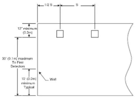
Figure 7-1: Smooth Ceiling (Side View)
![graph TD A["1/4 S maximum"] --> B["Box"] B --> C["1/2 S maximum"] C --> D["ReflectorTx/Rx"] D --> E["S"] E --> F["16 ft. (5m) minimum 328 ft. (100m) maximum"] F --> G["Reflector"]](/content/2026/06/1371334/images/13e083e2f38079761ed24fee106417d7f7783f9325b9b8b5de4583dfe3ffc803.jpg)
Figure 7-2: Smooth Ceiling (Top View)
In the case of peaked or sloped ceilings, codes may specify spacing of detectors by using horizontal spacing from the peak of the roof or ceiling. Figure 7-3 and Figure 7-4 show the spacing for both the shed type a peaked type sloped ceilings.
On smooth ceilings, beam smoke detectors should generally be mounted a minimum of 12 inches (0.3m) from the ceiling or beneath structural obstructions such as joists, ducts, etc. See Figure 7-1 In addition, beam smoke detectors should be mounted vertically at least 10 feet (3.0 m) from the floor to avoid common obstructions from normal building usage. In many cases, however, the location and sensitivity of the detectors shall be the result of an engineering evaluation that includes the following: ceiling heights above 3 feet (9.1 m) – refer to OSID Global Application Note, document no. (25686) for more information regarding the effects of stratification, structural features, size and shape of the room and bays, occupancy and uses of the area, ceiling height, ceiling shape, surface and obstructions, ventilation, ambient environment, burning characteristics of the combustible materials present, and the configuration of the contents in the area to be protected.
As a rule, reflective objects such as ductwork or windows should be a minimum of +/- 2° out of the center the beam path of the beam.

Figure 7-3: Sloped Ceiling (Shed Type) Figure 7-4: Sloped Ceiling (Peaked Type)
8 Mounting Locations
Beam detectors require a stable mounting surface for proper operation. A surface that moves, shifts, vibrates or warps over time will make the system prone to nuisance alarm or trouble conditions. Initial selection of a proper mounting surface will eliminate false alarms and nuisance trouble signals.
Mount the detector on a stable mounting surface, such as brick, concrete, a sturdy load-bearing wall, suppo column, structural beam, or other surface that is not expected to experience vibration or large movement ov time. DO NOT MOUNT the beam detector on corrugated metal walls, sheet metal walls, external building sheathing, external siding, suspended ceilings, steel web trusses, rafters, non-structural beam, joists, or other such surfaces.
In cases where only one stable mounting surface as defined above can be used, the transmitter/receiver un should be mounted to the stable surface and the reflector should be mounted to the less stable surface. The reflector has a much greater tolerance for the unstable mounting locations defined above.
This page is intentionally left blank.
9 Mounting Instructions
9.1 Mounting the Reflector
Mount the reflector first.
The reflector can be mounted to the wall using the supplied drilling template see (Appendix II. Reflector Drilling Template). The reflector has 4 mounting holes, one in each corner.
All four-hole locations should be used to provide a secure mounting. The reflector must be mounted such that it is within 10° in both the X and Y planes of the transmitter/receiver unit. See Figure 9-1 and Figure 9-2. reflector must also be mounted such that the plane of the reflector is perpendicular to the optical line of sign, the transmitter/receiver unit. The maximum tolerance for non-perpendicular mounting locations is 10° . See Figure 9-3.
If the reflector cannot be mounted within 10° of the transmitter/receiver unit then the multi-mount kit (6500MMK) may be used to provide greater angular adjustment of the transmitter/receiver unit. If the perpendicular plane of the reflector cannot be mounted within 10° of the optical line of sight then the multi-mount kit can be used for the reflector.

Figure 9-1: Reflector Mounting Guidelines

Figure 9-2: Reflector Mounting Guidelines

Figure 9-3: Reflector Mounting Guidelines
9.2 Mounting the Imager
The transmitter/receiver unit can be surface mounted, Cable knock-outs are provided top, bottom and back in the back box.
The transmitter/receiver unit may be mounted over a recessed junction box.
The cavity behind the detector is then used for routing of the wiring from the junction box to the terminal b on the detector by drilling holes through the detector's back box.
The transmitter/receiver unit should be mounted to the wall such that the unit covers the recessed junction box in the wall completely.
The transmitter/receiver unit can be mounted to the wall using the backbox pilot holes for 4" junction box. detector base has 5 pilot mounting keyholes spread around the base, see Figure 9-4. Any suitable number locations should be used to provide a secure mounting.
The outer housing of the beam detector is held to the base using three screws. To mount the detector, yo must remove the outer housing first.

Figure 9-4: Mounting pilot holes
10 Mounting Considerations for Single Ended Beam Detectors
There must be a permanent clear line of vision between the detector and the reflector. Reflective objects m not be near the line of vision between the detector and reflector. Reflective objects too near to the line of can reflect the light beam from the transmitter to the receiver. If this occurs, the detector will not be able t distinguish these reflections from those of the reflector and the protected space will be compromised.
Reflective objects such as ductwork or windows should be a minimum of 15 inches (38.1cm) from the path the beam (TBC). In cases where reflective objects cannot be avoided, the complete reflector blockage test can be used to determine if the installation is acceptable.
For more information refer to section 13 and 15.
Light sources of extreme intensity such as sunlight and halogen lamps, if directed at the receiver, can cause dramatic signal change resulting in fault signals. To prevent this problem direct sunlight into the transmitter/receiver unit should be avoided. There should be a minimum of 10° between the pathway of the light source and detector and the line of sight between detector and reflector.
Operation of the detector through panes of glass should be avoided. Since single ended beam detectors operate on a reflection principle, a pane of glass perpendicular to the line of sight between the detector and reflector can reflect the light beam from the transmitter to the receiver. If the application requires operation through glass, use the dual ended imaging smoke beam detector from the OSID family offering.
Where high ceilings (more than 30 feet or 9.1 meters) are present additional beam smoke detectors mounted at multiple heights may be required to detect smoke at lower levels. For more information refer to section 7
This page is intentionally left blank.
11 Wiring Installation Guidelines
Always install all wiring in compliance with the National Electrical Codes, and/or the applicable local codes, and any special requirements of the local authority having jurisdiction. Proper wire gauges and suitable means for strain relief should be used. The conductors used to connect beam smoke detectors to control panels and accessory devices should be color-coded to reduce the likelihood of wiring errors. Improper connections can prevent a system from responding properly in the event of a fire.
Installation wire used for the beam detector shall be no smaller than 22 AWGF or bestmsystem performance, all wiring should be twisted pair and installed in separate grounded conduit. Do NOT mix fire system wiring in the same conduit as any other electrical wiring.
When installing the beam smoke detector in applications where the head unit will be mounted to either a w or the ceiling using the multi-mount kits (6500MMK) and flexible conduit will be used. The multi-mount kit 6500MMK must be installed with the cable before wring the unit.

Figure 11-1: Detector Mounting Guidelines
When the detector has been mounted over a recessed junction box, all wiring should be routed out of the and behind the detector to the bottom of the detector where the terminal blocks are located. When installing the wiring in the junction box be sure to leave enough wire in the box to connect to the terminal blocks. (Approximately 9" [23cm) of wire outside of the junction box will be required for proper installation). All wiring the detector is done via pluggable terminal blocks. To properly make electrical connections strip approximately 1/4" (6mm) of insulation from the end of the wire, sliding the bare end of the wire under the clamping plate screw.
Figure 11-2 shows the proper wiring diagram for either class A or class B operation.
Figure 11-3 shows all the wiring connections to the transmitter/receiver unit.
Figure 11-4 shows the connections that are necessary when using one of the optional remote test stations.
Figure 11-5 shows the remote outputs for trouble and alarm.
![graph TD subgraph Power + A["POWER IN (+) POWER OUT (+)"] --> B["POWER IN (-) POWER OUT (-)"] end subgraph INITIATING + C["ALARM COM ALARM COM"] --> D["ALARM COM ALARM COM"] E["ALARM NO ALARM NO"] --> F["ALARM NO ALARM NO"] end subgraph INITIATING - G["TROUBLE COM TROUBLE NC AUX (-) REMOTE ALARM OUT…](/content/2026/06/1371334/images/1fbea725a34bf8539858c93042adc3290a6ad08001e7c20e92f547c6b74241df.jpg)
NOTE: If other sensors are installed on the same loop, a listed end of line power supervision module is required.
Figure 11-2: Wiring Diagram
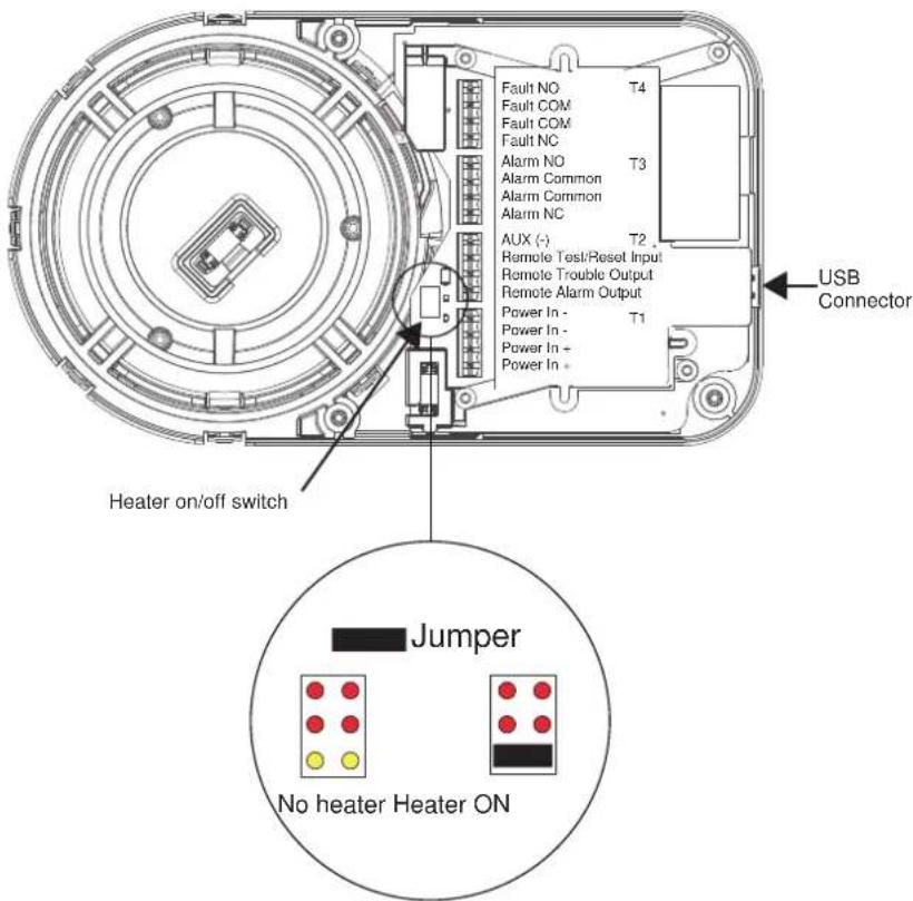
Figure 11-3: Wiring Connections at Detector
Warning: Disable the zone or system before applying power to the beam detector to prevent unwanted alarms. When applying power to the beam detector before the alignment procedure has been completed the detector will signal a trouble condition.
![graph TD A["OSI-R Terminals"] --> B["T2-1 Remote Alarm Output"] A --> C["T2-2 Remote Trouble Output"] A --> D["T2-3 Remote Test/Reset Input"] A --> E["T2-4 AUX -"] B --> F["RTS151/Key Terminals T1"] C --> G["External Jumper T3"] D --> H["External Resistor T4"] E --> I["10k ohm External Resistor T5"]](/content/2026/06/1371334/images/1c5ff38b9a592c347bf0d660ff0bdf6586f5112c06943a66422359b8838b8fe3.jpg)
Figure 11-4: Wiring Diagram (RTS451 or RTS151)
![graph TD A["Alarm Signal Circuit"] -->|T2-1| B["Red LED"] C["Trouble Signal Circuit"] -->|T2-2| D["Yellow LED"] E[" "] --> F["Red LED"] G[" "] --> H["Yellow LED"] I[" "] --> J["Red LED"] K[" "] --> L["Yellow LED"] M[" "] --> N["Red LED"]](/content/2026/06/1371334/images/3818e0342a1ae222d2ec655f4ad57cf727e14bbfcb79f1dbcfa2d687b3c68a98.jpg)
Figure 11-5: Wiring Diagram (Remote LEDs)
This page is intentionally left blank.
12 Installation/Alignment
Please make sure to complete all steps to ensure a successful installation.
Proper application, mounting, alignment, and set-up will minimize false alarms and nuisance trouble signals.
12.1 Pre-alignment Checklist
- Ensure that both the detector and reflector are mounted securely to stable surfaces.
- Ensure that all wiring is correct.
- Ensure that terminal blocks are fully seated into their receptacles on the detector.
- Complete any wiring dressing to minimize movement to the detector once the alignment procedure is completed.
- Ensure that the line of sight between the detector and reflector is clear and that reflective objects are not too near. See mounting instructions for more details.
- Remove the protective film from the lens surface of the imager.
- Ensure that both the detector and reflector are mounted within their operational parameters for off axis angles. See Mounting Instructions for more details.
- Disable the zone or system to prevent unwanted alarms before applying power.
- Ensure power to the detector is "ON".
You are now ready to begin the alignment procedure.
12.2 Coarse Alignment
Ensure that neither you nor any other objects are in the line of sight between the detector and the reflecto
Make sure the eyeball locking mechanism is unlocked. The lever is now in the 3 o'clock position and the eyeball moves freely.

By powering up the unit, the detector goes in alignment mode.
If the reflector is not in the field of view of the imager all 4 arrows will blink red.
For longer distances or in heavy lit environments use the OSP-002 Laser Alignment tool to roughly align the OSI-R-SS, OSI-RA-SS eyeball with the reflector. Make sure there are no people or objects obstructing your view of the reflector. This is also a good time to confirm that there are no obstructions or reflective objects within 15" (38.1cm) of the beam's path.
Insert the OSP-002 in the slot provided in the eyeball at 06.00 and move the eyeball.
The eyeball moves freely 50° horizontally and 20° vertically.
Gently move the eyeball till the red laser spot is on or near the reflector.
Once on the reflector, the laser dot will be clearly visible.
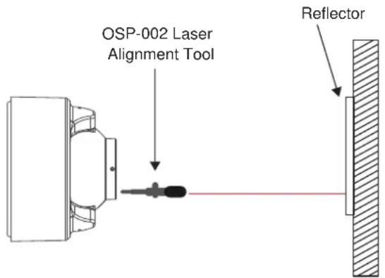
Figure 12-1: Coarse Alignment
12.3 Fine Adjustment
It is important to be well aligned as the IR power drops rapidly out of the centre of the beam.
The maximum beam size is dependent on the distance (D) between detector and reflector and can be calculated as 0.07x D.
Example, at 70 m/230 ft., the diameter of the beam will be +/- 5m/16.4 ft.

Figure 12-2: Beam Power Distribution
The 4 arrows will intuitively guide the user to optimal eyeball alignment. All arrows and the middle green LI must blink green for the eyeball to be optimal aligned. Likely the alignment process will start with all arrows red.
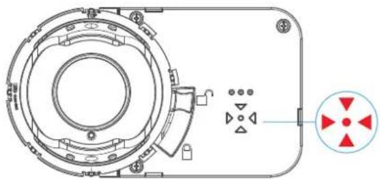
Figure 12-3: Arrow Array
Gently move the eyeball and let the arrow's colour, changing colour red to orange to green, as the alignment improves guide you till the all arrows and the middle LED turn green.
Example:
![graph LR A["Reflector"] --> B["Maximum beam power"] B --> C["Maximum beam size"] C --> D["Direction to move eyeball"] D --> E["Fully aligned"]](/content/2026/06/1371334/images/8254d95f9f32664b3678394a5a23e89a4650e97c06b4c6d7aea7217e96756b29.jpg)
Figure 12-4: Arrow Array Color Alignment Guidance
The unit is now optimal aligned. Now gently lock the eyeball by moving the lever down till the eyeball is locked. The lever is now in the 5 o'clock position and you feel the resistance of the locked position.
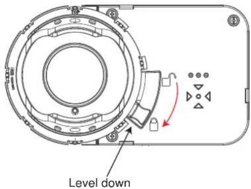
Figure 12-5: Locking and Securing the Eyeball
By locking the eyeball an internal switch is activated and the detector will now start its initiation or commissioning process. A normal commissioning process takes roughly 10 seconds. During the commissioning process, the beam path has to remain clear from object intrusions.
In this process cycle the detector will measure the size of the reflector in its FOV and determine the distar between detector and reflector. Based on this measurement, the sensitivity will be automatically set to the optimum sensitivity for the specific distance.
The process is finalised when the 4 arrows and the middle green LED stop blinking green. Before going in operational mode, the detector will show its set sensitivity. This is shown by blinking the 4 arrows. The number of blinks is, reflecting the % of selected obscuration/sensitivity. The key is; 1 blink = 25%, 2 blinks 30%, 3 blinks = 40% and 4 blinks= 50%. After 5 seconds, the scenario will be repeated a second time an than, the arrows LEDs go out and the front OK LED blinks green. The detector is now in operation and w correctly.
12.4 Completing the Installation
The paintable cover can now be snapped over the front to secure the locking lever and to hide the alignm LEDS and locking mechanism.
If the cover was painted, ensure that the paint is completely dry before installing. Mark the set sensitivity of the inside the cover for later use.
12.5 Final Verification
- Block the entire reflector with an opaque material. Nearly any non-reflective opaque material will do, including the installation sheet or the cardboard packaging inserts.
The detector should enter a trouble condition, indicated by the fault relay and the yellow LED (see A Appendix I. Operation Modes and Troubleshooting Guide OSI-R-SS, OSI-RA-SS: ) after 30 seconds. If the detector does not enter a trouble condition, there is a problem with the installation. Refer to troubleshooting section in A Appendix I. Operation Modes and Troubleshooting Guide OSI-R-SS, OSI-RA-SS: . for assistance.
- Complete by testing the detector using the test filter to create an alarm.
Note: Before testing, notify the proper authorities that the smoke detector system is undergoing maintenance, and therefore the system will be temporarily out of service. Disable the zone or system undergoing maintenance to prevent unwanted alarms.
Before testing the detector, check for the presence of the flashing green OK LED at the receiver, making s not to disturb or block the beam. If it does not flash and the detector is not in trouble or alarm, power ha lost to the detector (check the wiring).
This page is intentionally left blank.
13 Testing and Determining the Sensitivity of the
13.1 Calibrated Test Filter
13.1.1 Testing at the Imager
A quick test can be performed at the imager side by using the red acrylic test filter, OSP-004.
- Place the filter in front of the imager's lens. The detector should enter alarm within 1 minute.
- The detector can be reset with the remote reset or by momentarily interrupting power.
- Notify the proper authorities that the system is back on line.
At each reset action, the detector will show its set sensitivity.
After the RED alarm LED is off, the yellow alignment arrows on the front will indicate the set sensitivity by number of blinks from the arrows to indicate the set level.
The key is; 1 blink = 25%, 2 blinks = 30%, 3 blinks = 40% and 4 blinks = 50%.
After 5 seconds, the scenario will be repeated a second time.
After this, the detector will now be in normal working condition.
13.1.2 Testing at the Reflector
A thorough test should be performed at the reflector side, see "Testing at the Imager". The sensitivity of the detector must be noted during the quick test at the end of the initial set-up procedure.
- The sensitivity of the detector can be verified using the test filter to cover the reflector. The detector can be reset with the remote reset or by momentarily interrupting power.
- Notify the proper authorities that the system is back on line.
If the detector fails this test several steps should be taken to determine if the detector is faulty or simply n to be re-adjusted before returning the unit.
These steps include:
- Verify all wiring connections and appropriate power is applied to the detector.
- Verify that the optical line of sight is free from obstructions and reflective objects.
- Apply the maintenance procedure in this manual. Repeat the test procedure.
- If the detector still fails the test procedure proceed with step 4.
- Repeat the alignment procedure in this manual. If the alignment procedure is successful repeat the test procedure. If the detector still fails the test it should be returned.
13.2 Remote Test Station
The detector can be tested remotely using the remote test station.
Follow instructions included with the test station for proper use. See Figure 11-4 (Remote Test Station) for wiring diagram.
When activating the test, the detector will reduce the power output of the IR signal to the point where it dr below the automatically set sensitivity at the detector.
The detector will remain in alarm condition for as long as the test switch is activated. The detector can be reset by selecting the reset position on the RTS151KEY.
The remote fault LED will blink the set sensitivity of the detector. The number of blinks, similar to number of blinks from the arrows, will represent the set sensitivity and the sequence is repeated every 3 seconds till the detector is reset.
The LEDs at the remote test station will mimic the detector front LEDs.
Note: For the OSI-R-SS, OSI-RA-SS this test does not satisfy the requirements of NFPA72 for periodic maintenance and sensitivity verification of beam type detectors.
For the OSI-R-SS, OSI-RA-SS this test in conjunction with the complete reflector blockage test (see step 4 the Installation/Alignment procedure in this manual) does satisfy the requirements of NFPA72 for periodic maintenance and sensitivity verification of beam type detectors.
If the detector fails this test several steps should be taken to determine if the detector is faulty or simply r to be re-adjusted before returning the unit for repair. These steps include:
- Verify all wiring connections and appropriate power is applied to the detector.
- Verify that the optical line of sight is free from obstructions and reflective objects.
- Apply the maintenance procedure in this manual. Repeat the test procedure. If the detector still fails the test procedure proceed with step 4.
- Repeat the alignment procedure in this manual. If the alignment procedure is successful repeat the test procedure. If the detector still fails the test it should be returned.
Detectors must be tested after installation and following periodic maintenance.
Congratulations. You have completed the final installation and alignment procedure.
14 Operation After A Power Failure
The detector has the reflector location/position, set sensitivity and other commissioning parameters permanently memorised after the initialisation process.
After a power failure of any duration, when the supply is restored the detector will check the possible new situation versus it memorised data.
If the reflector is found in the same position and all parameters are within acceptable limits, the detector will resume its operation and go out of fault condition.
If any significant parameters have changed, it will remain in a fault condition and a re-initialisation will be required.
This page is intentionally left blank.
15 Maintenance
Note: Before cleaning the detector, notify the proper authorities that the smoke detector system is undergoing maintenance, and therefore the system will be temporarily out of service. Disable the zone or system undergoing maintenance to prevent unwanted alarms.
- Carefully clean the outer housing lens face. A damp soft cloth with a mild soap may be used. Avoid products with solvents or ammonia.
- Carefully clean the reflector. A damp soft cloth with a mild soap may be used. Avoid products with solvents or ammonia.
- Notify the proper authorities that the system is back on line.
This page is intentionally left blank.
16 Painting
The outer aesthetic ring may be painted using a spray or brush type paint of appropriate type. For more information refer to section 1.
Note: Never paint the flat lens surface of the imager.
This page is intentionally left blank.
17 Special Note Regarding Smoke Detector Guards
Smoke detectors are not to be used with detector guards unless the combination has been evaluated and found suitable for that purpose.
This page is intentionally left blank.
A Appendix I. Operation Modes and Troubleshooting Guide OSI-R-SS, OSI-RA-S
| Modes | Red and Remote Alarm Output | Yellow and Remote Trouble Output | Green Initiating means Comments and Troubleshooting Tips | |
| Power On Off Blink Off Apply Power from discharged state. | All wiring correctly done.Address switches set. | |||
| Alignment | Off Blink Off Lever | in 3:00 position and commissioning is active. | Ready to perform alignment.Follow guidance from the 4 arrows to correctly align. | |
| Initializing/Commissioning | Off Blink Off Lock | lever in 6:00 position to start | commissioning. | Commissioning and setting sensitivity.Do not interrupt beam. |
| Normal | Off | Off | Blink | Successful completion of initialization or detector reset.Initializing finished.Detector operates normal in quiescent conditionDetector successfully reset. |
| Alarm | On | Off | Off | Smoke, Test Filter or RTS151KEY Test Station.Blinks till reset from FACP or RTS151KEY. |
| Trouble-Drift Compensation | Off | 3 Quick Blinks | Blink | Long Term Drift Reference Out of 20% Range.Reduced IR Signal.Clean detector and reflector. |
| Trouble-Beam Blockage | Off 4 Quick Blinks | Blink Beam blockage or detector out of alignment.Remove blockage or re-align detector.Faulty unit. | ||
| Trouble-Imager saturation | Off 5 Quick Blinks | Blink Imager saturated.Sunlight or very strong light into detector or reflector.Re-position detector or reflector.Remove light source. | ||
| Test activated-Pass Result | On | Blinks the set sensitivity by number of blinks (1-4). Repeats every 3 seconds till reset. | Off FACP or RTS151KEY.Remains in alarm until reset by FACP or RTS151KEY.Arrows blink sensitivity level that was selected automatically. | |
Blink patterns
- OK/Green:
- Imager will flash green once every 5 seconds.
- Alarm/Red:
- Imager red solid on.
- Faults/Yellow:
• Number of pulses identifies type of fault.
• Rhythm; every pulse 15ms ON/15ms OFF, repeat after 2 seconds till fault has disappeared.
- Blinks only highest priority fault.
B Appendix II. Reflector Drilling Template

FCC STATEMENT
This device complies with part 15 of the FCC Rules. Operation is subject to the following two conditions: (1) This device may not cause harmful interference, and (2) this device must accept any interference received, including interference that may cause undesired operation.
Note: This equipment has been tested and found to comply with the limits for a Class B digital device, pursuant to Part 15 of the FCC Rules. These limits are designed to provide reasonable protection against harmful interference in a residential installation. This equipment generates, uses and can radiate radio frequency energy and, if not installed and used in accordance with the instructions, may cause harmful interference to radio communications. However, there is no guarantee that interference will not occur in a particular installation.
If this equipment does cause harmful interference to radio or television reception, which can be determined turning the equipment off and on, the user is encouraged to try to correct the interference by one or more following measures:
- Reorient or relocate the receiving antenna.
- Increase the separation between the equipment and receiver.
- Connect the equipment into an outlet on a circuit different from that to which the receiver is connected.
- Consult the dealer or an experienced radio/TV technician for help.
THREE-YEAR LIMITED WARRANTY
System Sensor warrants its enclosed smoke detector to be free from defects in materials and workmanship under normal use and service for a period of three years from date of manufacture. System Sensor makes other express warranty for this smoke detector.
No agent, representative, dealer, or employee of the Company has the authority to increase or alter the obligations or limitations of this Warranty. The Company's obligation of this Warranty shall be limited to the repair or replacement of any part of the smoke detector which is found to be defective in materials or workmanship under normal use and service during the three year period commencing with the date of manufacture.
After phoning System Sensor's toll free number 800-SENSOR2 (736-7672) for a Return Authorization number send defective units postage prepaid to: Honeywell, 12220 Rojas Drive, Suite 700, El Paso TX 79936, USA Please include a note describing the malfunction and suspected cause of failure. The Company shall not be obligated to repair or replace units which are found to be defective because of damage, unreasonable use, modifications, or alterations occurring after the date of manufacture. In no case shall the Company be liable for any consequential or incidental damages for breach of this or any other Warranty, expressed or implied whatsoever, even if the loss or damage is caused by the Company's negligence or fault. Some states do r allow the exclusion or limitation of incidental or consequential damages, so the above limitation or exclusion may not apply to you. This Warranty gives you specific legal rights, and you may also have other rights wI vary from state to state.


- OSI-R-SS, OSI-RA-SS SINGLE-ENDED REFLECTED TYPE PROJECTED IMAGING BEAM SMOKE DETECTOR - CONVENTIONAL
- INTELLECTUAL PROPERTY AND COPYRIGHT
- DISCLAIMER
- GENERAL WARNING
- CRITICAL PRODUCT SECURITY
- OPEN SOURCE SOFTWARE
- FIRMWARE UPDATES
- DEVICE AND SYSTEM SECURITY
- LIABILITY
- FITNESS FOR PURPOSE
- TOTAL LIABILITY
- INDEMNIFICATION
- MISCELLANEOUS
- DOCUMENT CONVENTIONS
- CONTACT US
- CODES AND STANDARDS INFORMATION FOR SMOKE DETECTION
- CONTROL PANEL COMPATIBILITY
- PRODUCT LISTINGS
- TABLE OF CONTENTS
- 1 SPECIFICATIONS
- 2 BEFORE INSTALLATION
- 3 GENERAL DESCRIPTION
- 4 SPECIAL APPLICATIONS
- 5 APPROVED ACCESSORIES
- 5.1 6500MMK
- 5.2 BEAMHKR
- 5.3 RTS151KEY (TEST STATION)
- 6 PACKAGE CONTENTS
- 7 DETECTOR PLACEMENT
- 7.1 EXAMPLE FOR SPACING ACCORDING TO NFPA 72
- 8 MOUNTING LOCATIONS
- 9 MOUNTING INSTRUCTIONS
- 9.1 MOUNTING THE REFLECTOR
- 9.2 MOUNTING THE IMAGER
- 10 MOUNTING CONSIDERATIONS FOR SINGLE ENDED BEAM DETECTORS
- 11 WIRING INSTALLATION GUIDELINES
- 12 INSTALLATION/ALIGNMENT
- 12.1 PRE-ALIGNMENT CHECKLIST
- 12.2 COARSE ALIGNMENT
- 12.3 FINE ADJUSTMENT
- 12.4 COMPLETING THE INSTALLATION
- 12.5 FINAL VERIFICATION
- 13 TESTING AND DETERMINING THE SENSITIVITY OF THE
- 13.1 CALIBRATED TEST FILTER
- 13.1.1 TESTING AT THE IMAGER
- 13.1.2 TESTING AT THE REFLECTOR
- 13.2 REMOTE TEST STATION
- 14 OPERATION AFTER A POWER FAILURE
- 15 MAINTENANCE
- 16 PAINTING
- 17 SPECIAL NOTE REGARDING SMOKE DETECTOR GUARDS
- BLINK PATTERNS
- B APPENDIX II. REFLECTOR DRILLING TEMPLATE
- FCC STATEMENT
- THREE-YEAR LIMITED WARRANTY
Brand : System Sensor
Model : OSI-R-SS
Category : Smoke detector