
2WTA-B - Smoke detector System Sensor - Free user manual and instructions
Find the device manual for free 2WTA-B System Sensor in PDF.


| Product Type | Photoelectric Smoke Detector (2-wire with sounder) |
| Brand | System Sensor |
| Model | 2WTA-B |
| Dimensions (including base) | 5.3 in diameter x 2.0 in height |
| Weight | 7.1 oz |
| Operating Voltage (Nominal) | 12/24 V (min 8.5 V, max 35 V) |
| Standby Current | 50 μA average |
| Alarm Current | 130 mA max (direct power) |
| Audible Alarm | 85 dBA min at 3 ft, temporal pattern (ANSI S3.41) |
| Operating Temperature Range | 32 to 100°F (0 to 37.8°C) |
| Operating Humidity Range | 0 to 95% RH non-condensing |
| Sensing Technology | Photoelectric with optical chamber and microprocessor |
| Thermal Detection | Fixed temperature 135°F (57.2°C) |
| Freeze Detection | Trouble indication below 41°F (5°C) |
| Sounder | Piezoelectric horn, 85 dBA min |
| Tamper Resistant | Yes, requires tool for removal |
| Remote Annunciator Output | 7 mA maximum, compatible with RA400Z/RA100Z |
| Maintenance Signal | Yes, via i3 Ready panel or 2W-MOD2 |
| Loop Test | EZ Walk loop test feature |
| Cleaning | Annual vacuuming or canned air |
| Warranty | 3 years limited from date of manufacture |
Frequently Asked Questions - 2WTA-B System Sensor
User questions about 2WTA-B System Sensor
0 question about this device. Answer the ones you know or ask your own.
Ask a new question about this device
Download the instructions for your Smoke detector in PDF format for free! Find your manual 2WTA-B - System Sensor and take your electronic device back in hand. On this page are published all the documents necessary for the use of your device. 2WTA-B by System Sensor.
USER MANUAL 2WTA-B System Sensor
ELECTRICAL SPECIFICATIONS
| 2-wire 4-wire | |||
| System Voltage -Nominal: 12/24 12/24 V(Non-polarized for 2WTR-B and 4WTR-B) | |||
| Min.: 8.5 10 V | |||
| Max.: | 35 35 | V | |
| Max. Ripple Voltage: | 30 30 | % peak to peak of applied voltage | |
| Avg. Standby Current: | 50 | 50 | μA average |
| Peak Standby Current: | 100 | — μA | |
| Max. Alarm Current | |||
| 4WTA-B, 4WTR-B: | — 35 | mA | |
| 4WTAR-B, 4WITAR-B: | — 50 | mA | |
| 2WTR-B: | 130 | — mA panel must limit current | |
| 2WTA-B: | 130* | ||
| Alarm Contact Ratings: | — | 0.5 | A @ 30 V AC/DC |
| Form C Contact Ratings: | 2 | 2 | A @ 30 V AC/DC |
| Audible Signal(temp-3 tone): | 85 | 85 | dBA min. in alarm or supply polarity reversed (Sounder units only) |
| Remote Annunciator Output: | 7 — mA maximum | ||
| EOL Relay: | — | 12/24 | EOLR-1 |
| Reset Time (min): | 0.3 0.3 seconds | ||
| Max. Start-up Capacitance: | 0.1 — μF | ||
| Max. Initial Start-up Time: | 45 | 15 | seconds |
| AlarmVerification** Start-up Time: | 15 | 15 | seconds |
*Direct Power (Non-reverse Polarity): 130 mA limited by panel.
Reverse Polarity Power: 30mA for the 2WTA-B in alarm; 12mA for all other 2WTA-B units on the loop. Add 25mA for the RRS-MOD reversing relay alarm current.
**Assumes the panel's alarm verification reset time is 10 seconds or less. Should the alarm verification reset exceed 10 seconds, use the maximum initial start-up time.
PHYSICAL SPECIFICATIONS
| Heat Sensor: | 135°F (57.2°C) |
| Freeze Trouble: | 41°F (5°C) |
| Operating Temperature Range: | 32 to 100°F (0 to 37.8°C) |
| Operating Humidity Range: | 0 to 95% RH non-condensing |
| Storage Temperature Range: | -4 to 158°F (-20 to 70°C) |
| Diameter (including base): | 5.3 inches |
| Height (including base): | 2.0 inches |
| Weight: | 7.1 oz. |
BEFORE INSTALLING
Please read thoroughly System Sensor's Applications Guide for System Smoke Detectors (SPAG91), which provides detailed information on detector spacing, placement, zoning, wiring, and special applications. This is available online from System Sensor's web site: www.systemsensor.com.
NOTICE: This manual shall be left with the owner/user of this equipment.
IMPORTANT: This detector must be tested and maintained regularly following National Fire Protection Association (NFPA) 72 National Fire Alarm Code requirements. At a minimum, cleaning should be performed annually.
GENERAL DESCRIPTION
Models 2WTR-B and 2WTA-B are 2-wire photoelectric smoke detectors; models 4WTR-B, 4WTA-B, 4WTAR-B, and 4WITAR-B are 4-wire photoelectric smoke detectors. All models incorporate a state-of-the-art optical sensing chamber and an advanced microprocessor. The microprocessor allows the detector to automatically adjust its sensitivity back to the factory setting when it becomes more sensitive due to contaminants settling in its chamber. In order for this feature to work properly, the chamber must never be opened while power is applied to the smoke detector. This includes cleaning, maintenance or screen replacement. All models also feature a restorable, built-in, fixed temperature (135°F) thermal detector and are also capable of sensing a freeze condition if the temperature is below 41°F.
Models 2WTA-B, 4WTA-B, 4WTAR-B, and 4WITAR-B contain a piezoelectric horn which generates the ANSI S3.41 temporal pattern in an alarm condition.
All detectors on a zone will sound when the power supply to them is reversed. The RRS-MOD can be used for the power supply reversal function. The RRS-MOD also enables all the detectors' sounders on a zone to be synchronized and allows the zone to be silenced from the panel by entering the alarm silence key at the keypad.
The detector that initiated the alarm condition will have its red LED and Form C relays (if applicable) latched until reset by panel.
The model 4WITAR-B photoelectronic smoke sensor is isolated from the fixed-temperature heat sensor, providing a self-resetting, local audible smoke alarm that does not alarm at the panel. Only the fixed-temperature heat sensor will cause the 4WITAR-B to initiate an alarm at the panel and the relay to change its state.
NOTE: In order for all i3 sounder detectors on a loop to sound when the panel alarms, the supply voltage polarity must be reversed. A reversing relay, System Sensor model number RRS-MOD, must be used. The RRS-MOD is designed to allow all i3 Series detectors in the same loop to sound when one of the detectors goes into alarm. In addition, the RRS-MOD will synchronize all of the i3 Series sounder smoke detectors on the loop. Some panels may require the use of programmable outputs. Refer to System Sensor literature for further information on the RRS-MOD.
All i 3 Series detectors are designed to provide open area protection. Two-wire models must be used with compatible UL Listed panels only.
When used with an “i 3 Ready” control panel or the i 3 Series 2W-MOD2 module (refer to installation manual), the 2WTR-B and 2WTA-B are capable of generating a “maintenance needed” signal. The 2W-MOD2 can indicate a need for cleaning, replacement, or a freeze trouble at the control panel or module.
WARNING
The 2W-MOD2 has replaced the previous model number 2W-MOD. To ensure proper remote maintenance signaling capabilities, do not use the 2W-MOD with i 3 model numbers 2WTR-B and 2WTA-B.
Installation of the 2WTR-B, 2WTA-B, 4WTR-B, 4WTA-B, 4WTAR-B, and 4WITAR-B detectors is simplified by the use of a mounting base that may be pre-wired to the system, allowing the detector to be easily installed or removed. The mounting base installation is further simplified by the incorporation of features compatible with drywall fasteners.
Two LEDs on the detector provide a local visual indication of the detector's status:
TABLE 1: DETECTOR LED MODES
| Green LED Red LED | ||
| Power-up Blink 10 sec | Blink 10 sec | |
| Normal (standby) Blink | 5 sec — | |
| Out of sensitivity — Blink | 5 sec | |
| Freeze Trouble — Blink | 10 sec | |
| Alarm — Solid |
During an initial power-up delay, the red and green LEDs will blink synchronously once every ten seconds. It will take approximately 80 seconds for the detector to finish the power-up cycle (see Table 2).
TABLE 2: POWER-UP SEQUENCE FOR LED STATUS INDICATION*
| Condition Duration | |
| Initial LED Status Indication 80 seconds | |
| Initial LED Status Indication(if excessive electrical noise is present) | 4 minutes |
*Refer to Electrical Specifications for start-up time in conjunction with panel alarm verification.
NOTE: If, during power-up, the detector determines there is excessive electrical noise in the system such as those caused by improper grounding of the system or the conduit, both LEDs will blink for up to 4 minutes before displaying detector status (see Table 2).
After power-up has completed and the detector is functioning normally within its listed sensitivity range, the green LED blinks once every five seconds. If the detector is in need of maintenance because its sensitivity has shifted outside the listed limits, the red LED blinks once every five seconds. When the detector is in the alarm mode, the red LED latches on. The LED indication must not be used in lieu of the tests specified under Testing. In a freeze trouble condition, the red LED will blink once every 10 seconds (refer to Table 1).
To measure the detector's sensitivity, the i3 Series Model SENS-RDR Infrared Sensitivity Reader tool (see Figure 4) should be used. Refer to instructions manual D100-98-00 for the proper use of the SENS-RDR.
Models 2WTR-B and 2WTA-B also include an output that allows an optional Model RA400Z/RA100Z Remote Annunciator to be connected.
MOUNTING
General spacing guidelines are 30 × 30 , with each detector covering 900 ft 2 under maximum conditions.
Consult NFPA 72, the local Authority Having Jurisdiction (AHJ), and/or applicable codes for specific information regarding the spacing and placement of smoke detectors.
Each i 3 Series detector is supplied with a mounting base that can be ceiling- or wall-mounted:
- To a single gang box, or
- To a 31/2-inch or 4-inch octagonal box, or
- To a 4-inch square box with a plaster ring, or
- Direct mount or to ceiling using drywall fasteners.
FIGURE 1: MOUNTING OF DETECTOR

The r3 Series heads and bases are keyed so that all heads will only fit into their respective bases. One model 4-wire relay base will accept the 4WTR-B, 4WTAR-B and 4WITAR-B detector heads and no others. The 2WTR-B, 2WTA-B and 4WTA-B will only fit into their respective mounting bases and no others. The heads and bases are clearly identified as either 2-wire or 4-wire. When mounting the r3 Series, ensure that the head is mounted to the correct base, and the test switch is aligned with the tamper release tab.
TAMPER-RESISTANT FEATURE
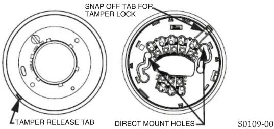
The 1 Series detectors include a tamper-resistant feature that prevents removal from the mounting base without the use of a tool. To engage the tamper-resistant feature, cut the small plastic tab located on the mounting base (Figure 2), and then install the detector. To remove the detector from the base once it has been made tamper resistant, use a small screwdriver to depress the square tamper release tab, located on the skirt of the mounting base, and turn the detector counterclockwise.
INSTALLATION GUIDELINES
The i 3 Series detectors represent an advancement over the previous sounder and Form C relay models and are designed to be used with the 2W-MOD2 and RRS-MOD only. Do not mix detector models on a zone.
FIGURE 2: TAMPER-RESISTANT FEATURE
WIRING INSTALLATION GUIDELINES
All wiring must be installed in compliance with the NFPA 70, National Electrical Code, applicable state and local codes, and any special requirements of the local Authority Having Jurisdiction.
Proper wire gauges should be used. The conductors used to connect smoke detectors to the alarm control panel and accessory devices should be color-coded to reduce the likelihood of wiring errors. Improper connections can prevent a system from responding properly in the event of a fire.
The screw terminals in the mounting base will accept 14–22 gauge wire. For best system performance, all wiring should be installed in separate grounded conduit; do not mix fire alarm system wiring in the same conduit as any other electrical wiring. Twisted pair may be used to provide additional protection against extraneous electrical interference.
Wire connections are made by stripping approximately 1/4-inch of insulation from the end of the feed wire, inserting it into the proper base terminal, and tightening the screw to secure the wire in place. Do not put wires more than 2 gauge apart under the same clamping plate.
TWO-WIRE COMPATIBILITY
System Sensor two-wire smoke detectors are marked with a compatibility identifier located on the label on the back of the product. For two-wire models 2WTR-B and 2WTA-B, connect detectors only to compatible alarm control panels as identified by System Sensor's two-wire compatibility chart, available at www.systemsensor.com.
NOTE: Models 2WTR-B and 2WTA-B are not to be installed on initiating circuits containing other makes/models of smoke detectors.
NOTE: Style D initiating circuits require the use of a 2W-MOD2 for models 2WTR-B and 2WTA-B.
WIRING DIAGRAMS
FIGURE 3A: WIRING DIAGRAM, 2WTR-B AND 2WTA-B

S0122-00
NOTE: FOR ALL COMPATIBLE ADEMCO PANELS, DO NOT EXCEED 30 OHMS LINE IMPEDANCE.
NOTE: ONLY ONE 2WTR-B DETECTOR PER ZONE CAN BE USED.
NOTE: Only one 2WTA-B detector shall be installed on a zone, unless the panel switches the zone to a reverse polarity, non-current limited power supply. For panels that do not provide this feature, a reversing relay, System Sensor model RRS-MOD, may be used. When utilized with the 2WTA-B, it allows for more than one detector to be utilized on a loop. Some panels may require the use of programmable outputs. Refer to System Sensor literature for further information on the RRS-MOD. The 2WTA-B detector shall not be mixed with other 2-wire detectors on the same zone.
CAUTION
Any 2-wire i 3 smoke detector (2W-B, 2WT-B, 2WTA-B, or 2WTR-B) wired in the Style D initiating device circuit (IDC) configuration requires the use of a 2W-MOD2 module. This is because fire alarm control panels vary by manufacturer on the implementation of Style D circuits. Therefore, the only way to insure proper operation of 2-wire i 3 smoke detectors (2W-B, 2WT-B, 2WTA-B, or 2WTR-B) on Style D IDC's is to use a 2W-MOD2 module. Refer to the 2W-MOD2 installation manual, document D500-46-00, for Style D wiring diagrams. The 2W-MOD2 installation manual may be downloaded from the System Sensor web site at www.systemsensor.com.
FIGURE 3B: WIRING DIAGRAM, 4WTR-B, 4WTA-B, 4WTAR-B, AND 4WITAR-B

S0123-01
INSTALLATION
WARNING
Remove power from alarm control unit or initiating device circuits before installing detectors.
NOTE: To install units so that corresponding LEDs are lined up, refer to the "Green LED" indicator on the base.
- Wire the mounting base screw terminals per Figure 3a or Figure 3b, as applicable.
-
Place detector on the base and rotate clockwise. The detector will drop into the base and lock into place with a "click".
-
After all detectors have been installed, apply power to the alarm control unit.
- Test each detector as described in Testing.
- Reset all the detectors at the alarm control unit.
- Notify the proper authorities that the system is in operation.
CAUTION
Dust covers are an effective way to limit the entry of dust into the smoke detector sensing chamber during construction. However, they may not completely prevent airborne dust particles from entering the detector. Therefore, System Sensor recommends the removal of detectors before beginning construction or other dust producing activity. When returning the system to service, be sure to remove the dust covers from any detectors that were left in place during construction.
CAUTION
Smoke detectors are not to be used with detector guards unless the combination has been evaluated and found suitable for that purpose.
CAUTION
When using the RRS-MOD with model 2WTA-B, do not mix the 2WTA-B with other model smoke detectors and dry contact closure devices, including mechanical heat detectors, manual pull stations and waterflow switches. Such mixing can cause a direct short on the auxiliary power terminals, damaging the control panel's internal circuitry and/or damage devices connected to the initiating device circuit.
TESTING
Detectors must be tested after installation and following maintenance.
NOTE: Before testing, notify the proper authorities that maintenance is being performed and the system will be temporarily out of service. Disable the zone or system undergoing maintenance to prevent any unwanted alarms.
Ensure proper wiring and power is applied. After power up, allow 80 seconds for the detector to stabilize before testing.
Test P Series detectors as follows:
A. TEST SWITCH
- An opening for the recessed test switch is located on the detector housing (See Figure 4).
- Insert a small screwdriver or allen wrench (0.18" max.) into the test switch opening; push and hold.
- If the detector is within the listed sensitivity limits, the detector's red LED should light within one second.
FIGURE 4: RECESSED TEST SWITCH OPENING AND SENS-RDR POSITION

S0110-00
B. SMOKE ENTRY TEST
Canned aerosol simulated smoke (canned smoke agent) may be used for smoke entry testing of the smoke detector. Tested and approved aerosol smoke products are:
| MANUFACTURER MODEL | |
| Home Safeguard Industries | 25S, 30S |
| SDi | CHEK02 and CHEK06 |
| SDi | SOLOA4 |
| SDi | SMOKESABRE-01 |
When used properly, the canned smoke agent will cause the smoke detector to go into alarm. Refer to the manufacturer's published instructions for proper use of the canned smoke agent.
CAUTION
Canned aerosol simulated smoke (canned smoke agent) formulas will vary by manufacturer. Misuse or overuse of these products may have long term adverse effects on the smoke detector. Consult the canned smoke agent manufacturer's published instructions for any further warnings or caution statements.
C. DIRECT HEAT METHOD
Using a 1000-1500 watt hair dryer, direct the heat toward either of the thermistors. Hold the heat source about 12 inches from the detector to avoid damage to the plastic.
NOTE: For the above tests, the detector will reset only after the power source has been momentarily interrupted. It is not necessary to reset the model 4WITAR-B, when smoke is used to initiate the alarm.
When testing the 4WITAR-B model, pressing the test switch will result in a non-latching local alarm that does not alarm at the control panel. Once the test button is released, the unit will return to its standby condition. Only the fixed-temperature heat sensor will cause the 4WITAR-B to initiate an alarm at the panel.
If a detector fails any of the above test methods, its wiring should be checked and it should be cleaned as outlined in the Maintenance section. If the detector still fails, it should be replaced.
Notify the proper authorities when the system is back in service.
LOOP VERIFICATION (MODELS 2WTR-B AND 2WTA-B ONLY)
Loop verification is provided by the EZ Walk loop test feature. This feature is for use with i3 Series compatible control panels or the i3 Series 2W-MOD2 module only. The EZ Walk loop test verifies the initiating loop wiring and provides visual status indication at each detector. Refer to System Sensor literature for further information on the 2W-MOD2.
WARNING
The 2W-MOD2 has replaced the previous model number 2W-MOD. To ensure proper EZ Walk Test capabilities, do not use the 2W-MOD with 1 model numbers 2WTR-B and 2WTA-B.
TABLE 3: EZ WALK TEST DETECTOR MODES
| Green LED Red LED | ||
| Proper Operation Double blink 5 sec — | ||
| Out of Sensitivity — Double Blink 5 sec | ||
| Freeze Condition — Double Blink 10 sec | ||
NOTE: The EZ Walk loop test must not be used instead of alarm testing.
MAINTENANCE
NOTE: Before performing maintenance on the detector, notify the proper authorities that maintenance is being performed and the system will be temporarily out of service. Disable the zone or system undergoing maintenance to prevent any unwanted alarms. Power must be removed from the detector before performing maintenance of any kind.
- Remove the detector cover by turning counterclockwise. (See Figure 5.)
- Vacuum the cover or use canned air to remove any dust or debris.
- Remove the top half of the screen/sensing chamber by lifting straight up. (See Figure 5.)
- Vacuum or use canned air to remove any dust or particles that are present on both chamber halves.
- Replace the top half of the screen/sensing chamber by aligning the arrow on the screen/sensing chamber with the arrow on the housing. Press down firmly until the screen/sensing chamber is fully seated.
- Replace the detector cover by placing it over the screen/sensing chamber and turning it clockwise until it snaps into place.
- Reinstall the detector and test. (See the Testing section.)
- Notify the proper authorities when the system is back in service.
FIGURE 5: REMOVING SCREEN/SENSING CHAMBER

Please refer to insert for the Limitations of Fire Alarm Systems
THREE-YEAR LIMITED WARRANTY
System Sensor warrants its enclosed product to be free from defects in materials and workmanship under normal use and service for a period of three years from date of manufacture. System Sensor makes no other express warranty for the enclosed product. No agent, representative, dealer, or employee of the Company has the authority to increase or alter the obligations or limitations of this Warranty. The Company's obligation of this Warranty shall be limited to the replacement of any part of the product which is found to be defective in materials or workmanship under normal use and service during the three year period commencing with the date of manufacture. After phoning System Sensor's toll free number 800-SENSOR2 (736-7672) for a Return Authorization number, send defective units postage prepaid to: Honeywell, 12220 Rojas Drive, Suite 700, El Paso
TX 79936, USA. Please include a note describing the malfunction and suspected cause of failure. The Company shall not be obligated to replace units which are found to be defective because of damage, unreasonable use, modifications, or alterations occurring after the date of manufacture. In no case shall the Company be liable for any consequential or incidental damages for breach of this or any other Warranty, expressed or implied whatsoever, even if the loss or damage is caused by the Company's negligence or fault. Some states do not allow the exclusion or limitation of incidental or consequential damages, so the above limitation or exclusion may not apply to you. This Warranty gives you specific legal rights, and you may also have other rights which vary from state to state.
FCC STATEMENT
This device complies with part 15 of the FCC Rules. Operation is subject to the following two conditions: (1) This device may not cause harmful interference, and (2) this device must accept any interference received, including interference that may cause undesired operation.
NOTE: This equipment has been tested and found to comply with the limits for a Class B digital device, pursuant to Part 15 of the FCC Rules. These limits are designed to provide reasonable protection against harmful interference in a residential installation. This equipment generates, uses and can radiate radio frequency energy and, if not installed and used in accordance with the instructions, may cause harmful interference to radio communications. However, there is no guarantee that interference will not occur in a particular installation. If this equipment does cause harmful interference to radio or television reception, which can be determined by turning the equipment off and on, the user is encouraged to try to correct the interference by one or more of the following measures:
- Reorient or relocate the receiving antenna.
- Increase the separation between the equipment and receiver.
- Connect the equipment into an outlet on a circuit different from that to which the receiver is connected.
- Consult the dealer or an experienced radio/TV technician for help.
i 3 is a trademark of and System Sensor and Honeywell are registered trademarks of Honeywell International, Inc.


- BEFORE INSTALLING
- GENERAL DESCRIPTION
- WARNING
- MOUNTING
- TAMPER-RESISTANT FEATURE
- INSTALLATION GUIDELINES
- WIRING INSTALLATION GUIDELINES
- TWO-WIRE COMPATIBILITY
- WIRING DIAGRAMS
- FIGURE 3A: WIRING DIAGRAM, 2WTR-B AND 2WTA-B
- CAUTION
- INSTALLATION
- TESTING
- TEST SWITCH
- SMOKE ENTRY TEST
- DIRECT HEAT METHOD
- LOOP VERIFICATION (MODELS 2WTR-B AND 2WTA-B ONLY)
- MAINTENANCE
- PLEASE REFER TO INSERT FOR THE LIMITATIONS OF FIRE ALARM SYSTEMS
- THREE-YEAR LIMITED WARRANTY
- FCC STATEMENT
Brand : System Sensor
Model : 2WTA-B
Category : Smoke detector