BEAM-MMK - Detector System Sensor - Free user manual and instructions
Find the device manual for free BEAM-MMK System Sensor in PDF.


| Product Type | Reflective Beam Smoke Detector |
| Brand | System Sensor |
| Model | BEAM-MMK |
| Detection Range | 30 to 100 meters (98 to 328 feet) |
| Operating Voltage | 24 VDC (18-32 VDC) |
| Current Consumption | 20 mA (standby), 60 mA (alarm) |
| Temperature Range | -10°C to 55°C (14°F to 131°F) |
| Humidity Range | 0-95% non-condensing |
| Dimensions (Detector Unit) | 200 x 200 x 100 mm (7.9 x 7.9 x 3.9 in) |
| Weight | 0.5 kg (1.1 lb) |
| Enclosure Material | Polycarbonate, gray |
| Alarm Output | Form C relay (SPDT), 2 A @ 30 VDC |
| Sensitivity Levels | 4 selectable levels (low, med, high, very high) |
| Alignment | Built-in laser alignment tool |
| LED Indicators | Red (alarm), green (power/standby), yellow (trouble) |
| Wire Connections | Screw terminals, 12-22 AWG |
| Certifications | UL, FM, CSFM (pending) |
| Application | Indoor use, open areas with high ceilings |
| Maintenance | Clean optics annually with soft cloth |
| Warranty | 5 years limited |
Frequently Asked Questions - BEAM-MMK System Sensor
User questions about BEAM-MMK System Sensor
0 question about this device. Answer the ones you know or ask your own.
Ask a new question about this device
Download the instructions for your Detector in PDF format for free! Find your manual BEAM-MMK - System Sensor and take your electronic device back in hand. On this page are published all the documents necessary for the use of your device. BEAM-MMK by System Sensor.
USER MANUAL BEAM-MMK System Sensor
Notice: This manual should be left with the owner/user of this equipment.
GENERAL DESCRIPTION
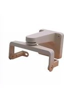
The BEAMMMK allows reflected beam detectors and reflectors to be mounted to either a vertical wall or the ceiling. The kit allows for additional alignment range in cases where the detector and reflector cannot be mounted within 10° of each other. The kit includes the hardware necessary to mount either a single transmitter/receiver unit or a single reflector. (To mount the transmitter/receiver the surface mount kit, BEAMSMK, must also be used). If the transmitter/receiver and the reflector require additional alignment range two kits are required. The kit is not compatible with the long-range reflector kit (BEAMLRK).
The kit includes the following parts:
Qty. Description
1 Ceiling mount bracket inside
1 Ceiling mount bracket outside
1 Wall mount bracket
1 "U" bracket
2 “L” bracket
1 Horizontal adjustment screw (ceiling) #10-24 × 2 1/4 "
1 Horizontal adjustment screw (wall) #10-24 × 1 3 /8"
2 Allen screw #10-24 × 1/2 "
2 Allen screw #10-24 × 5/8"
2 Fender washer plastic
2 Fender washer metal
2 Washer plastic #10
2 Washer metal #10
2 Washer metal split-lock #10
2 Hex nut #10-24
1 Allen wrench
MOUNTING BRACKETS
Install a ceiling or wall bracket so that when mounted, the transmitter/receiver and the reflector will have a clear line of sight between them.
The ceiling bracket is composed of two parts that should be assembled with the inside part between the ceiling and the outside part as shown in Figure 1. The brackets should be mounted so that the slot in the front of each bracket is facing the other bracket. Mount the brackets only on solid structures of the building. To avoid unwanted alarms due to wall movement, do not mount to flexible walls, such as sheet metal walls (see Mounting Locations section of the transmitter/receiver manual for more details).
FIGURE 1. CEILING MOUNT BRACKET ASSEMBLY:

MOUNTING AND WIRING INSTRUCTIONS:
TRANSMITTER/RECEIVER
The BEAMSMK accessory must be used with the transmitter/receiver to provide wiring entry. Refer to Figures 2 through 4 for this step.
- Read the installation instructions of the beam detector to determine the appropriate size and number of wires to be used.
- Drill the appropriate holes for the flexible conduit using the drill centers provided on either the sides or the back of the surface mount base. See Figure 2 for details. Note that the top of the surface mount base contains mounting bosses for the "L" brackets used in the next step. Conduit sizes of 1/2'' or 3/4'' are acceptable.
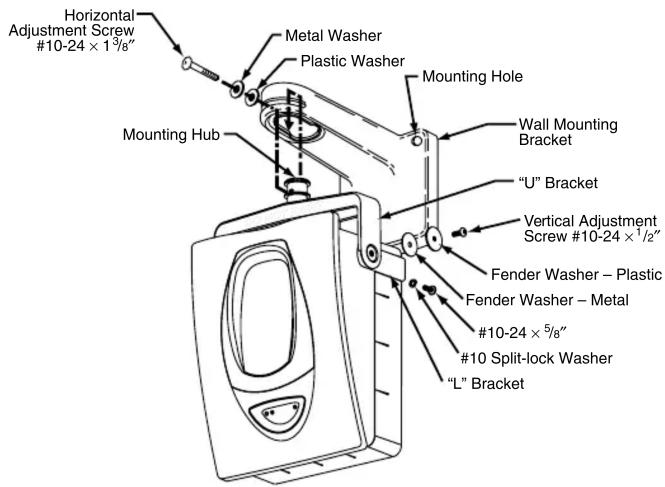
- Assemble the "L" brackets to the surface mount base using the two #10-24 × 5 / 8 " screws and two #10 split-lock washers provided. See Figure 3 for details. The screws should be fully tightened.
- Assemble the "U" bracket to the "L" brackets using the two #10-24 × 1/2 " screws and fender washers provided. See Figure 3 for details. The "U" bracket should be assembled to the "L" brackets so that the words "DO NOT PAINT" appear in the front of the assembly. Tighten the screws until almost snug. The assembly should tilt freely in either direction. The screws will be fully tightened later when the alignment is performed.
- Insert the flange of the "U" bracket into the keyed hole of the wall or ceiling mount bracket. Slide the bracket forward into position. The surface mount base should now hang from the bracket.
- Insert the correct screw and washer combination (either wall or ceiling mount) through the slot and into the hole of the mounting bracket flange. Tighten the screw until almost snug. The assembly should still
turn freely in both directions. The screw will be fully tightened later when the alignment is performed.
- Pull the wiring and the flexible conduit through the drilled hole(s). Attach nut(s) (not included) to conduit fitting and tighten.
NOTE: Be sure to leave enough wire to reach the transmitter/receiver unit when attached to the surface mount base. Be sure to leave enough flexible conduit so that the transmitter/receiver unit can be adjusted to aim at the reflector.
- Attach the transmitter/receiver unit securely to the base using the four #8-32 × 1/2" screws supplied with the BEAMSMK accessory.
- Adjust the transmitter/receiver unit so that it is aiming directly at the reflector. Once aimed correctly fully tighten both vertical and horizontal adjustment screws.
NOTE: For proper operation of the beam detector it must be securely mounted to ensure no subsequent movement of the beam detector will occur after the installation is completed. See “Detector Placement and Mounting” sections of the beam detector manual for further details.
FIGURE 2. BEAMSMK WIRING LOCATIONS:

FIGURE 3. WALL MOUNTING TRANSMITTER/RECEIVER UNIT:
C0312-00
- Complete the installation of the transmitter/receiver unit using the instructions included with the beam detector.
- Test the system as indicated in the beam detector instructions.
MOUNTING INSTRUCTIONS: REFLECTOR
Refer to Figure 4 for this step.
- Assemble the "L" brackets to the reflector using the two # 10 - 24×5 / 8 screws, two #10 split-lock washers, and two #10 locknuts provided. See Figure 4 for details. The screws should be fully tightened.
- Assemble the "U" bracket to the "L" brackets using the two #10-24 × 1/2" screws and fender washers provided. See Figure 4 for details. The "U" bracket should be assembled to the "L" brackets so that the words "DO NOT PAINT" appear in the front of the assembly. Tighten the screws until almost snug. The assembly should tilt freely in either direction. The screws will be fully tightened later when the alignment is performed.
- Insert the flange of the "U" bracket into the keyed hole of the wall or ceiling mount bracket. Slide the bracket forward into position. The reflector should now hang from the bracket.
- Insert the correct screw and washer combination (either wall or ceiling mount) through the slot and into the hole of the mounting bracket flange. Tighten the screw until almost snug. The assembly should still turn freely in both directions. The screw will be fully tightened later when the alignment is performed.
- Adjust the reflector so that it is aiming directly at the transmitter/receiver unit. Once aimed correctly fully tighten both vertical and horizontal adjustment screws.
NOTE: For proper operation of the beam detector the reflector must be securely mounted to ensure no subsequent movement will occur after the installation is completed. See “Detector Placement and Mounting” sections of the beam detector manual for further details.
- Test the system as indicated in the beam detector instructions.
FIGURE 4. CEILING MOUNTING REFLECTOR:


Brand : System Sensor
Model : BEAM-MMK
Category : Detector