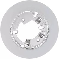
B300-6-BP - Detector System Sensor - Free user manual and instructions
Find the device manual for free B300-6-BP System Sensor in PDF.


| Product Type | 6-inch Plug-in Detector Base |
| Model | B300-6-BP |
| Brand | System Sensor |
| Base Diameter | 6.1 inches (155 mm) |
| Base Height | 0.76 inches (19 mm) |
| Operating Voltage | 15 to 32 VDC |
| Standby Current | 170 μA |
| Listings | UL268 |
| Compatible Detectors | Refer to Base/Sensor Cross Reference Chart at systemsensor.com |
| Wiring Terminals | Screw terminals for Power (+/-) and Remote Annunciator |
| Mounting Compatibility | 4-inch square (with/without plaster rings), 4-inch octagon, 3.5-inch octagon, single gang boxes |
| Tamper-Resist Feature | Yes, with breakable tab |
| Remote Annunciator Support | Yes, model RA100Z |
| Wire Gauge Range | 18 AWG to 12 AWG (0.823 mm² to 3.31 mm²) |
| Maximum Wire Size Under Terminal | Up to 12 AWG with proper stripping |
| Communication | Over power lines (+ and -) |
| Application | Intelligent fire alarm systems |
| Standards Compliance | NFPA 72 guidelines |
| Warranty | Three-year limited from date of manufacture |
| Maintenance | Clean detector at least once a year |
| Decorative Ring | Removable trim ring with snap-on |
| Terminal Layout | Terminal 1: Power (-), Remote Annunciator (-); Terminal 2: Power (+); Terminal 3: Remote Annunciator (+) |
Frequently Asked Questions - B300-6-BP System Sensor
User questions about B300-6-BP System Sensor
0 question about this device. Answer the ones you know or ask your own.
Ask a new question about this device
Download the instructions for your Detector in PDF format for free! Find your manual B300-6-BP - System Sensor and take your electronic device back in hand. On this page are published all the documents necessary for the use of your device. B300-6-BP by System Sensor.
USER MANUAL B300-6-BP System Sensor
B300-6 and B300-6-IV
6" Plug-in Detector Bases
3825 Ohio Avenue, St. Charles, Illinois 60174
1-800-SENSOR2, FAX: 630-377-6495
www.systemsensor.com
SPECIFICATIONS
Base Diameter: 6.1 inches (155 mm)
Base Height: 0.76 inches (19 mm)
Operating Temperature:
Electrical Ratings:
Operating Voltage: 15 to 32 VDC
Standby Current: 170 μA
Listings: UL268
Refer to applicable sensor Operating Temperature Range using the Base/Sensor Cross Reference Chart at systemsensor.com.
BEFORE INSTALLING
Please read the System Smoke Detectors Application Guide, which provides detailed information on detector spacing, placement, zoning, wiring, and special applications. Copies of this application guide are available from System Sensor. NFPA 72 guidelines should be observed.
NOTICE: This manual should be left with the owner/user of this equipment.
IMPORTANT: The detector used with this base must be tested and maintained regularly following NFPA 72 requirements. The detector should be cleaned at least once a year.
GENERAL DESCRIPTION
The B300-6 and B300-6-IV are plug-in detector bases intended for use in an intelligent system, with screw terminals provided for power (+ and -), and remote annunciator connections. Communication takes place over the power lines (+ and -).
BASE TERMINALS
NO. FUNCTION
1 Power (−), Remote Annunciator (−) 2 Power (+) 3 Remote Annunciator (+)
FIGURE 1. TERMINAL LAYOUT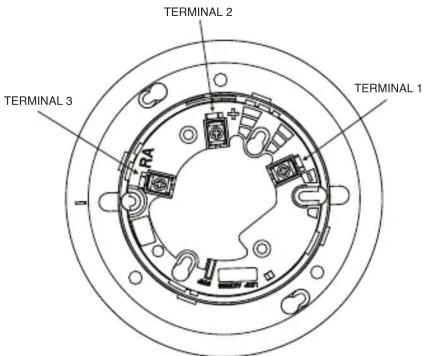
C0127-07
MOUNTING
This detector base mounts directly to 4-inch square (with and without plaster rings), 4-inch octagon, 3-1/2-inch octagon, and single gang junction boxes. To mount, remove the decorative ring by turning it in either direction to unhook the snaps, then separate the ring from the base. Install the base on the box using the screws supplied with the junction box and the appropriate mounting slots in the base.
Place the decorative trim ring on the base and rotate it in either direction until it snaps into place. (See Figure 2.)
FIGURE 2. MOUNTING DETECTOR TO BOX
C2036-01
INSTALLATION AND WIRING GUIDELINES (SEE FIGURE 3)
All wiring must be installed in compliance with all applicable local codes and any special requirements of the authority having jurisdiction. Proper wire gauges should be used. The conductors used to connect smoke detectors to control panels and accessory devices should be color-coded to reduce the likelihood of wiring errors. Improper connections can prevent a system from responding properly in the event of a fire.
For signal wiring (the wiring between interconnected detectors), it is recommended that the wire be no smaller than 18 AWG (0.823 mm²). Wire sizes up to 12 AWG (3.31 mm²) may be used with the base.
Make electrical connections by stripping about 3/8 inch (10 mm) of insulation from the end of the wire (use strip gauge molded in base). Then slide the wire under the clamping plate and tighten the clamping plate screw. Do not loop the wire under the clamping plate. (See Figure 4.)
Check the zone wiring of all bases in the system before installing the detectors. This includes checking the wiring for continuity, correct polarity, ground fault testing and performing a dielectric test.
The base includes an area for recording the zone, address, and type of detector being installed. This information is useful for setting the detector head address and for verification of the detector type required for that location.
Once all detector bases have been wired and mounted, and the loop wiring has been checked, the detector heads may be installed in the bases.
TAMPER-RESIST FEATURE
NOTE: Do not use the tamper-resist feature if a removal tool will be used.
The detector base includes a tamper-resist feature that prevents removal of the detector without using a small screwdriver or similar tool.
To activate this feature, use needle-nose pliers to break the tab on the detector base as shown in Figure 5A. Then, install the detector.
To remove the detector from the base once the tamper-resist feature has been activated, remove the decorative ring by rotating it in either direction and pulling it away from the base. Then, insert a small screwdriver into the notch, as indicated in Figure 5B, and press the plastic lever toward the mounting surface before rotating the detector counterclockwise for removal.
The tamper-resist feature can be defeated by breaking and removing the plastic lever from the base. However, this prevents the feature from being used again.
REMOTE ANNUNCIATOR (RA100Z)
Connect the remote annunciator between terminals 1 and 3 using the spade lug terminal included. The spade lug terminal is connected to the base terminal as shown in Figure 6.
It is not acceptable to have three stripped wires under the same wiring terminal unless they are separated by a washer or equivalent means. The spade lug supplied with the model RA100Z is considered an equivalent means. See Figure 3 for proper installation.
FIGURE 3. TYPICAL WIRING DIAGRAM FOR 2-WIRE LOOP
FIGURE 4. TERMINAL WIRE INSTALLATION
FIGURE 5A. ACTIVATE TAMPER-RESIST FEATURE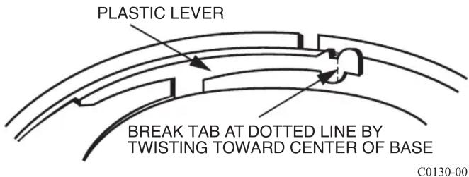
FIGURE 5B. DETECTOR REMOVAL
FIGURE 6. CONNECTION TO REMOTE ANNUNCIATOR TERMINAL

Please refer to insert for the Limitations of Fire Alarm Systems
THREE-YEAR LIMITED WARRANTY
System Sensor warrants its enclosed smoke detector base to be free from defects in materials and workmanship under normal use and service for a period of three years from date of manufacture. System Sensor makes no other express warranty for this smoke detector base. No agent, representative, dealer, or employee of the Company has the authority to increase or alter the obligations or limitations of this Warranty. The Company's obligation of this Warranty shall be limited to the repair or replacement of any part of the smoke detector base which is found to be defective in materials or workmanship under normal use and service during the three year period commencing with the date of manufacture. After phoning System Sensor's toll free number 800-SENSOR2 (736-7672) for a Return Authorization number, send defective units postage prepaid to: Honeywell,
12220 Rojas Drive, Suite 700, El Paso TX 79936 USA. Please include a note describing the malfunction and suspected cause of failure. The Company shall not be obligated to repair or replace units which are found to be defective because of damage, unreasonable use, modifications, or alterations occurring after the date of manufacture. In no case shall the Company be liable for any consequential or incidental damages for breach of this or any other Warranty, expressed or implied whatsoever, even if the loss or damage is caused by the Company's negligence or fault. Some states do not allow the exclusion or limitation of incidental or consequential damages, so the above limitation or exclusion may not apply to you. This Warranty gives you specific legal rights, and you may also have other rights which vary from state to state.
System Sensor® is a registered trademark of Honeywell International, Inc.
2 I56-6566-001
©2017 System Sensor. 11/17/2017

- B300-6 AND B300-6-IV
- 6" PLUG-IN DETECTOR BASES
- SPECIFICATIONS
- BEFORE INSTALLING
- GENERAL DESCRIPTION
- BASE TERMINALS
- MOUNTING
- INSTALLATION AND WIRING GUIDELINES (SEE FIGURE 3)
- TAMPER-RESIST FEATURE
- REMOTE ANNUNCIATOR (RA100Z)
- PLEASE REFER TO INSERT FOR THE LIMITATIONS OF FIRE ALARM SYSTEMS
- THREE-YEAR LIMITED WARRANTY
Brand : System Sensor
Model : B300-6-BP
Category : Detector