
Skyline 70 - Tripod Miller - Free user manual and instructions
Find the device manual for free Skyline 70 Miller in PDF.


| Product Type | Tripod with Fluid Head |
| Brand | Miller |
| Model | Skyline 70 |
| Maximum Load Capacity | 20 kg (44 lbs) |
| Minimum Height | 30 cm (11.8 in) |
| Maximum Height | 160 cm (63 in) |
| Leg Sections | 3 |
| Leg Lock Type | Twist lock (quick-release) |
| Leg Material | Carbon fiber |
| Head Type | Fluid drag head |
| Bubble Level | Yes (included) |
| Weight | 3.5 kg (7.7 lbs) |
| Folded Length | 70 cm (27.6 in) |
| Warranty | 2 years |
| Recommended Use | Professional video and cine cameras |
| Maintenance | Clean with a soft dry cloth; store in a dry place; avoid solvents. |
| Safety | Do not exceed maximum load; ensure leg locks are firmly tightened before use. |
| Spare Parts | Available through authorized dealers; contact Miller support. |
| General Information | Designed for smooth pan and tilt operation; compatible with 75mm bowl. |
Frequently Asked Questions - Skyline 70 Miller
User questions about Skyline 70 Miller
0 question about this device. Answer the ones you know or ask your own.
Ask a new question about this device
Download the instructions for your Tripod in PDF format for free! Find your manual Skyline 70 - Miller and take your electronic device back in hand. On this page are published all the documents necessary for the use of your device. Skyline 70 by Miller.
USER MANUAL Skyline 70 Miller
natural_image
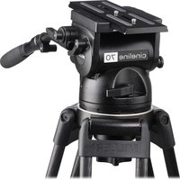
Black studio Skyline 70 camera tripod with attached camera module and stand (no visible text or symbols on device body)Features and Controls

Features and Controls

Introduction Safety Instructions
Thank you for purchasing the Skyline 70 Fluid Head. The Skyline 70 Fluid Head has been designed to suit payload capacities of EFP, OB and Studio camera systems.
The robust design and construction of the Skyline 70 Fluid Head offers maximum stability, accuracy and durability and includes precision ball bearing mounted Fluid Drag Plate system in the Pan and Tilt assembly to deliver true fluid drag performance over the entire temperature and payload range.
The Fluid Drag and the Counterbalance system were designed to provide excellent control and repeatability and offer progressive equal increments of drag and torque.
The Skyline 70 Fluid Head also offers Illuminated Pan, Tilt, Counterbalance settings and Bubble level.
The Skyline 70 Fluid Head will give best performance when used on Miller ∅150 HD Tripods. This will ensure maximum system stability to suit any professional set-up. The Skyline 70 Fluid Head will suit most industry standard 150 mm tripods as well, please refer to manufactures' manual for mounting details.
Please use this manual to familiarise yourself with the operation of the Skyline 70 Fluid Head and observe these instructions to prevent any damage to your equipment. Ensure that all equipment is operating correctly and free from defects and damage, also please ensure that the tripod is steady, secure and that the bowl is approximately horizontal when attaching the camera. The operator is responsible for the safe operation of this piece of equipment.
- Do not exceed the maximum payload capacity of the Fluid Head.
- Do not leave the camera unattended on the Fluid Head.
- Do not release the SLIDING PLATFORM LOCK whilst the camera is at an angle.
- Do not adjust the tripod whilst the camera is attached to the Fluid Head.
- Ensure PAN HANDLE CLAMP and CLAMP NUT is securely tightened.
- Apply TILT LOCK when adding/removing equipment from the camera or when attaching/removing the camera from the Fluid Head.
- Hold camera securely whilst changing Counterbalance, Pan Drag or Tilt Drag settings.
- Hold the camera securely whilst releasing the RELEASE KNOB.
- Hold camera securely whilst adjusting the CLAMP NUT to level the Fluid Head.
Technical Data
Weight 6.0 kg (13.2 lbs)
Payload Range 4.5 - 37.5 kg (9.9 - 82.5 lbs)
Maximum Capacity 40 kg (88 lbs)
Tilt Drag 7 Selectable fluid drag positions + 0
Tilt Range + 90° / -75°
Tilt Lock Positive Lock caliper brake system plus Safety Lock.
Pan Drag 7 Selectable fluid drag positions + 0
Pan Range 360°
Pan Lock Positive Lock caliper brake system
Counterbalance 8 Selectable positions (see System performance graph)
Camera Platform Quick release camera plate with 120 mm (4.72") travel and 2 x 3/8" camera screws.
Mounting Base ∅150 (5.9") mm Ball Levelling with 3 x M5 holes for Flat Base Mounting.
Ball Level Range 15°
Handle 2 x telescopic pan handles with adjustable reach & angle.
Temperature range -40°C to +65°C
Construction Lightweight diecast Aluminium alloy, moulded reinforced plastics
Sealing Water & Dust resistant
Finish Matt black (low sheen) durable powder coated with anti-corrosive pre treatment
Warranty 3 Years.
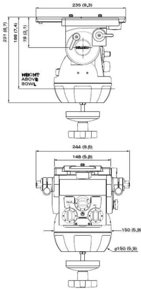
Fig. 3
Operating Instructions
The operating instructions are described in six steps. Please read and understand these instructions before using this equipment. Do not omit any steps.
1 Fluid Head Set-up
1.1 Loosen the PAN HANDLE CLAMP fully then rotate the PAN HANDLE until it is approximately perpendicular to the THREADED STUD (fig. 4) and tighten the PAN HANDLE CLAMP - avoid contact wear between the serrations on the Fluid Head and the PAN HANDLE CLAMP, if this occurs then unwind the PAN HANDLE CLAMP further.
1.2 Ensure that the TRIPOD BOWL is approximately horizontal. Place the Fluid Head into the TRIPOD BOWL, adjust the BUBBLE LEVEL (fig. 4) such that the bubble is inside the black circle and tighten the CLAMP NUT.
1.3 Set the initial control settings as follows - see Figure 1 & 2:
- Select Counterbalance to position 8 (top setting).
- Select Pan & Tilt Drag to position 0.
- Tighten the PAN LOCK, TILT LOCK and the SLIDING PLATFORM LOCK.

Fig. 4
Operating Instructions
2 Camera Set-up
2.1 Remove the CAMERA PLATE by pulling down the SAFETY TAB while rotating the QUICK RELEASE KNOB to the left. The CAMERA PLATE should pop out.
2.2 Refer to the Camera's owners manual for correct method of attachment to the CAMERA PLATE.
2.3 Attach camera accessories and the battery to the camera, it is recommended to estimate the camera's Centre of Gravity (C of G) for the purpose of correctly positioning the camera on the CAMERA PLATE. The camera's C of G can be estimated by placing the camera on to a round rod and then shifting it backwards or forwards until a balance point - C of G - is achieved. It is recommended to identify this point on the camera as it will be useful in step 2.6.
2.4 Attach the CAMERA PLATE to the camera and securely tighten the screws.
2.5 Align the CAMERA PLATE with the SLIDING PLATFORM and slide it in until the safety mechanism is engaged.
2.6 Release the SLIDING PLATFORM LOCK and slide the SLIDING PLATFORM such that the camera's C of G is directly above the centre axis of the Fluid Head and tighten the SLIDING PLATFORM LOCK (fig.5). If this can not be achieved then reposition the CAMERA PLATE on the Camera - step 2.4. This will ensure that the system has maximum stability.
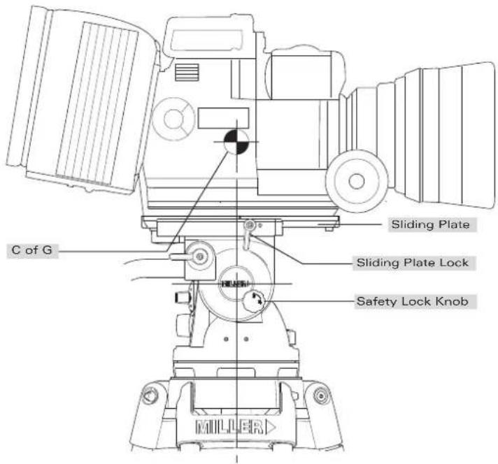
Fig. 5
Operating Instructions
3 Counterbalance Control
The counterbalance system was designed to neutralise the effect of the camera weight when it is tilted. The Skyline 70 Fluid Head offers an 8 position counterbalance system which can be operated via the COUNTERBALANCE SELECTOR (fig. 2). The COUNTERBALANCE SELECTOR must be operated when the SLIDING PLATFORM is in a horizontal position. After changing the Counterbalance setting it may be necessary to tilt the camera back and forth to ensure that the CB spring has engaged. The camera must be held securely while changing the Counterbalance setting.
3.1 For safety ensure that Counterbalance position 8 is selected.
3.2 Hold the camera and release the TILT LOCK, then gently tilt the camera from a horizontal position forward then backward and observe its response. If the Camera 'Springs Back' to the horizontal position then a lower Counterbalance setting is required, select Counterbalance position 7 and recheck, select lower setting again if necessary. Correct counterbalance setting has been achieved when minimum effort is required to move the camera over the entire tilt range.
TIP Fine tuning can be achieved by adjusting the SLIDING PLATFORM - see step 2.6.
Counterbalance Performance
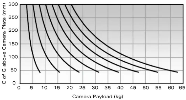
line
| Camera Payload (kg) | C of G above Camera Plate (mm) | | ------------------- | ------------------------------ | | 0 | 300 | | 5 | 250 | | 10 | 200 | | 15 | 150 | | 20 | 100 | | 25 | 75 | | 30 | 50 | | 35 | 25 | | 40 | 10 | | 45 | 5 | | 50 | 2.5 | | 55 | 1 | | 60 | 0.5 | | 65 | 0.25 |Fig. 6
Operating Instructions
4 Pan / Tilt Drag Control
The Skyline 70 Fluid Head offers 7 selectable positions of fluid drag + zero setting in the Pan and Tilt. The settings are equally stepped from light drag in position 1 up to heavy drag in position 7, the drag plates are completely disengaged in position zero.
- Do not Pan or Tilt the Fluid Head whilst adjusting PAN or TILT DRAG CONTROL or whilst the PAN & TIL DRAG CONTROL is between settings.
- The drag setting can be changed at any tilt or pan angle.
5 Pan / Tilt Lock Control
The Skyline 70 Fluid Head offers high capacity caliper disc brake system to hold the Fluid Head in a fixed pan and/or tilt position. Camera position will not change when applying or releasing the Pan / Tilt locks.
- Do not pan or tilt the Fluid Head whilst the PAN or the TILT LOCK is partially applied.
6 Illumination
The Skyline 70 Fluid Head offers illumination of the PAN, TILT, COUNTERBALANCE CONTROLS AND BUBBLE LEVEL when the low ambient light conditions exist. Illumination can be achieved by pressing the ILLUMINATION BUTTON once. The light will switch off after 10 seconds.
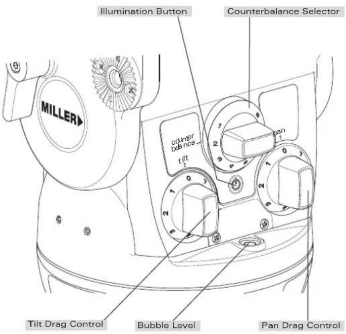
Fig. 7
Maintenance
The Skyline 70 Fluid Head offers high quality surface coatings. Miller recommends keeping the Fluid Head clean at all times by using soft brushes and lint free cloth to wipe over the surfaces.
- Do not immerse the Fluid Head in any liquid.
- Do not use stiff brushes, abrasives, harsh detergents and solvents.
Battery Replacement
The Skyline 70 Fluid Head uses a single GP23A type - 12 Volt battery for Illumination. Miller recommends the following batteries to provide long life performance - GP23A, Duracell MN21/23 or Vinnic L1028.
1 Using a Phillips Head #1 screw driver, remove the RETAINING SCREWS and the BATTERY DOOR.
2 Using a small flat screw driver remove the battery.
3 Align the new battery as shown on the back of the BATTERY DOOR and place into the BATTERY HOUSING, then push down the battery into place. A small flat screw driver may be used to push down the battery into the BATTERY HOUSING.
4 Align the BATTERY DOOR into the body then tighten the screws lightly.

Fig. 8
Storage Service, Sales and Support
The Skyline 70 Fluid Head can be stored for extended periods; Miller recommends storage in a Miller Soft Case and the following:
- Remove battery.
- Clean the external surfaces.
- Keep in a dry place away from direct sunlight.
- Loosen off PAN & TILT LOCK.
Spare Parts and Accessories
| ITEM ITEM NO. | |
| Battery 12V P3798 | |
| Camera Plate Assembly (Includes 2 x 3/8" screws) | #1060 |
| Camera screw 3/8" P0037 | |
| Camera screw 1/4" P0036 | |
| Telescopic Pan Handle assembly (including Handle Clamp) | #694 |
| Telescopic Pan Handle #692 | |
| Multi Hard Case with wheels #318 | |
| Clamp nut P8459 | |
| Accessory Mounting Bracket Ass'y #1221 | |
| Accessory Mounting Adaptor Ass'y #1217 | |
| Mitchell Flat Base Adaptor #1226 | |
Warranty
Please refer to warranty card for complete details.
Miller Authorised Service Agents must carry out all service and repair work. Failure to observe this requirement may void warranty. It is advisable to notify Miller or a Miller Authorised
Service Agent if a change of performance is observed as a result of dropping or rough usage. For information regarding sales and service of Miller products or for your nearest Miller representative please contact us via our website or at the following:
MILLER CAMERA SUPPORT EQUIPMENT
30 Hotham Parade, Artarmon, Sydney,
NSW 2064 Australia
Tel: +61 2 9439 6377 Fax: +61 2 9438 2819
Email: sales@miller.com.au
MILLER Camera Support (LLC) USA
218 Little Falls Road, Cedar Grove, New Jersey 07009-1231 USA
Tel: (973) 857 8300 Fax: (973) 857 8188
Email: sales@millertripods.us
MILLER FLUID HEADS (EUROPE) LTD.
Unit 12A, Shepperton Business Park
Govett Avenue, Shepperton, Middlesex TW17 8BA
United Kingdom
Tel: +44 (0)1243 555255 Fax: +44 (0)1243 555 001
Email: sales@millertripods-europe.com
www.millertripods.com
MILLER
www.millertripods.com
MILLER CAMERA SUPPORT EQUIPMENT
30 Hotham Parade
Artarmon, Sydney
NSW 2064 Australia
Tel: +61 2 9439 6377
Fax: +61 2 9438 2819

- Features and Controls
- Introduction Safety Instructions
- Technical Data
- Operating Instructions
- Fluid Head Set-up
- Camera Set-up
- Counterbalance Control
- Pan / Tilt Drag Control
- Pan / Tilt Lock Control
- Illumination
- Maintenance
- Battery Replacement
- Storage Service, Sales and Support
- Warranty
- MILLER CAMERA SUPPORT EQUIPMENT
- MILLER Camera Support (LLC) USA
- MILLER FLUID HEADS (EUROPE) LTD.
- MILLER
- www.millertripods.com
Brand : Miller
Model : Skyline 70
Category : Tripod