HD 150 - Tripod Miller - Free user manual and instructions
Find the device manual for free HD 150 Miller in PDF.

| Type | Tripod |
| Brand | Miller |
| Model | HD 150 |
| Material | Aluminum alloy |
| Height (max) | 170 cm (approx.) |
| Height (min) | 70 cm (approx.) |
| Weight | 10 kg (approx.) |
| Maximum Load | 30 kg |
| Leg Sections | 3 |
| Locking System | Flip locks with safety catches |
| Head Type | Fluid head (compatible) |
| Bubble Level | Yes |
| Spreader | Mid-level spreader |
| Rubber Feet | Yes, replaceable |
| Transport Case | Not included |
| Warranty | 5 years (manufacturer) |
| Compatibility | Miller HD series heads |
| Cleaning Instructions | Wipe with damp cloth, avoid solvents |
| Storage Temperature | -20°C to 60°C |
Frequently Asked Questions - HD 150 Miller
User questions about HD 150 Miller
0 question about this device. Answer the ones you know or ask your own.
Ask a new question about this device
Download the instructions for your Tripod in PDF format for free! Find your manual HD 150 - Miller and take your electronic device back in hand. On this page are published all the documents necessary for the use of your device. HD 150 by Miller.
USER MANUAL HD 150 Miller
natural_image
3D rendering of a cylindrical mechanical device with black and gray components (no text or symbols visible)
100mm Bowl Models
925 2-stage Carbon Fiber
931 1-stage Alloy
932 1-stage Alloy Studio
935 MINI 1-stage Alloy
150mm Bowl Models
937 2-stage Carbon Fiber
943 1-Stage Alloy
944 1-Stage Alloy Studio
945 MINI 1-Stage Alloy

ACCESSORIES & COMPONENTS SE
Cat # Description
180 Studio HD Dolly
483 Studio HD Dolly with Cable Guards and Track Lock
175 Rubber Feet (set of 3)
993 Mid Level Spreader
974 Softcase for HD 100 & HD 150 2-stage
P4816 Transport Clip
WARRANTY
Please refer to warranty card for complete details

VICE, SALES & SUPPORT
Miller Authorised Service Agents must carry out all service and repair work. Failure to observe this requirement may void warranty. It is advisable to notify Miller or a Miller Authorised Service Agent if a change of performance is observed as a result of dropping or rough usage. For information regarding sales and service of Miller products, or for your nearest Miller representative please contact us via our website or at the following:
MILLER CAMERA SUPPORT EQUIPMENT
30 Hoffam Parada, Arbanon, Sydney
NSH 2064 Australia
Tel +51 28439 6377 Fax +61 2 0188 2810
Email: saks@miller.com.au
MILLER CAMERA SUPPORT LLC (USA)
215 Lille Falls Road, Cedar Grove
New Jersey 07029-1231 USA
Tel: 1873; 567-6320 Fax: 1878; SET 8185
- 18731 507 0165
MILLER FLUID HEADS (Europe) LTD.
Unit A2, Ford Lane Industrial Estal
Ford Lane, Ford
West Sussex BN18 CDF, United Kingdom
Tel +44 1243 565 256
8244 01243 565 03
смен. ваймен-дипуск-еurope.com
WEBSITE www.millertripods.com
D4392-6 0908
FEATURES AND CONTROLS
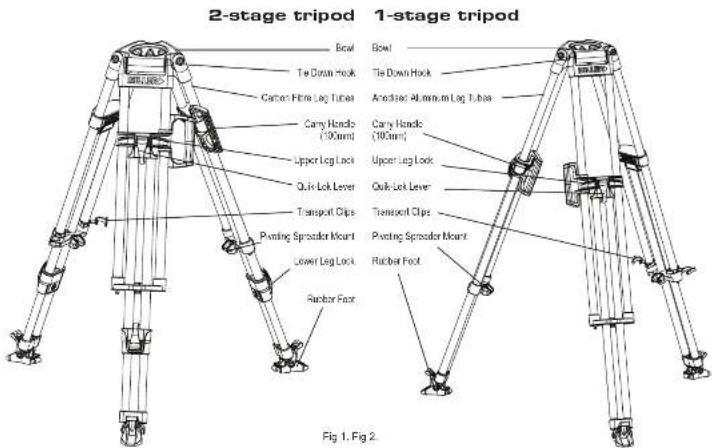
INTRODUCTION
Thank you for purchasing the HD Tripod. The HD Tripod has been designed to suit payload capacities from ENG up to full configuration EFP cameras. The HD Tripod is available with other a €100 mm or €150 mm bowl and as 1-Stage, 2-Stage, Studio or Mini models. The 2-Stage Tripod comes in ultralight, high strength carbon fibre tubing while the 1-Stage, Studio and the Mini Tripod comes in anodized alloy tubing. The HD Tripod is designed primarily to give excellent stability and durability. While many integrated features enable the user to operate the Tripod safely and easily - such as the Integrated Carry Handle (€100 mm bowl), Forever-Hat rubber fast and Fina height adjustable Mid-level aspirator.
The HD Tripod will give best performance when used with the Arrow Fluid Head range and OS-60 Fluid Head. This will ensure maximum system stability to suit any professional set-up. The HD Tripod will suit most industry standard ∅100 mm ∅150 mm Fluid Heads as well, please refer to manufacturers' manual for mounting details.
TECHNICAL DATA
C## 925 931 932 937 943 944 935 945
| Tone Configuration | 2-Stage | 1-Stage | Studio | 2-Stage | 1-Stage | Studio | Mini | Mini |
| Tone Vasceral | Carbon | Alcy | Alcy | Carbon | Alcy | Alcy | Alcy | Alcy |
| Bow Dra mm | 109 100 100 | 150 150 | 150 100 150 | |||||
| Maximum Load kg (lb) | 95 (210) | 95 (210) | 95 (210) | 95 (210) | 95 (210) | 95 (210) | 95 (210) | 95 (210) |
| Weight kg (lb) | 4.5 (39) | 5.2 (11.5) | 4.7 (10.4) | 4.6 (10.2) | 5.35 (11.5) | 4.8 (10.6) | 4.3 (8.5) | 4.2 (9.3) |
| Max Height mm (in') | 1590 (62.6) | 1578 (52.2) | 1270 (50.0) | 1515 (63.6) | 1590 (62.8) | 1290 (50.4) | 590 (37.0) | 570 (38.2) |
| Min Height mm (in) | 450 (18.5) | 785 (30.8) | 590 (23.2) | 510 (20.1) | 920 (31.5) | 510 (24.0) | 350 (13.8) | 370 (14.5) |
| Transport Length mm (in) | 750 (29.5) | 930 (35.6) | 782 (30.8) | 750 (28.5) | 940 (37.0) | 780 (31.1) | 655 (25.4) | 650 (25.5) |
TRIPOD SET-UP
- Before setting-up the tripod, the Mid Level Spreader must be attached.
- Remove tripod from the Softcase and unlock the Transport Clips.
- Place the Tripod Feet on level surface (if possible) and release the Quk Lok Upper Lever on each log.
- Lift the top of the tripod to a desired height and then apply the Quik Lok Upper Lever on each leg.
- Release the Quik Lok Lower Lever on each leg (2-Stage model), then lift the tripod to a desired height and apply the Quik Lok Lower Lever on each leg.
- Spread the Tripod Legs apart, check that the Tripod Bowl is approximately level to the ground.
- Check that the tripod is secure.
TRIPOD PULL DOWN
Remove the camera from the Fluid Head.1
Retract the spreader arms fully. 2.
Hold and lift off the ground by two legs, then bring the legs awards 3. While holding the top of the tripod, release the Quik Lok Upper Lever 4. and Quik Lok Lower Lever (2-Stage model) on each leg then lower completely.
Apply the Quik Lok Upper Lever and Quik Lok Lower Lever on each 5. log
Attach both Transport Clips and return the tripod to the Sollicase.5.
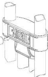
TRANSPORT CLIPS
The 2 Transport Clips (Fig.3) are designed to hold the HD tripod's three legs together during transport. Their spring-loaded design means they are easily gripped and detached
for set up, and just as easily snapped back on to the logs for transporting tripod. The Transport Cipe must be securely attached before transporting the tripod.
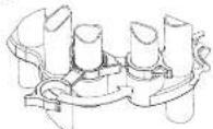
Fig 3.
CARRY HANDLE
Miller's 2-part Carry Handle (patented) (Fig 4.) is perfectly positioned to balance the tripod with the head attached.
NOTE: 1-Stage & 2-Stage 100mm tirpod models only
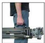
Fig 4.
LEG LOCK ADJUSTMENT
Over time the leg locks may need adjusting to prevent leg sippage.
Adjust the Upper Leg Lock Assembly in a locked position using 13mm Socket (Fig 5.)
- Extend the upper stage half way and lock the Upper Lever.
- Turn the Upper Leg lock adjuster clockwise 1/8th of a turn. Release Sprint Lok Upper Lever and ensure that stage slides freely.
- When adjusted correctly Log Lock Lover should only have a small amount of "free play" before locking action commences. If this free play is excessive repeat the steps above.
(Upper leg lock illustrated)
3m SOCKET
WARNING: ALWAYS ADJUST WITH LEVER IN LOCKED POSITION, ADJUST LOCK IN SMALL INCREMENTS, DO NOT OVER-TIGHTEN.
Fig 5.
natural_image
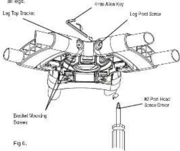
Technical line drawing of a mechanical component with cylindrical ends and a central circular feature (no text or symbols)LEG TO BOWL ADJUSTMENT
The leg to bowl pilot joint on the HD tripod should have no lateral or free play movement and should swing with a firm, smooth resistance. Adjustment is usually not required, however, should it become necessary, the following procedure must be observed. (Fig 6.)
-
Leg to Bowl Adjustment to eliminate lateral, or free play movement. Using a cross head screwdriver, ensure Bracket Mounting Screws on both sides of the Leg Top Bracket are light. Reighten if necessary. Check all legs.
-
Leg pivot or 'swing' adjustment to ensure firm, smooth resistance. Tighten the Leg Pivot Scrows on each side of the Leg Top Bracket using a 4mm alien key until a smooth resistance is maintained. Check
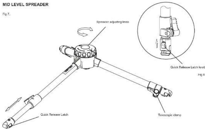
SPREADER
Mid Level Spreader (Fig 7.)
The Mid-Level Spreader allows the setting of the Tripods footprint and fine height adjustment. The tripod height and overall footprint can be adjusted by turning the Spreader Adjusting knob or by adjusting the length of the telescopic spreador arms.
Spreader Set-up
- Turn the Spreader Adjusting Knob counter-clock wise to the open position.
- Stand the Tripod upright with legs spread out equally.
- Release the Telescopic Clamp on the spreader arm then latch the Quick Release Latch on to the Pivoting Spreader Mount, repeat for the remaining two arms.
- Bring each Tripod leg in such that the corresponding Spreader arm is fully retracted then lock the Telescopic Clamp, repeat for each Spreader arm.
- Bring the Tripod legs towards the centre position, if resistance is felt do not force the Tripod legs, spread out the Tripod legs and make sure that the Spreader arms are fully retracted.
Spreader Pull Down
- Remove the Camera and the Fluid Head from the Tripod.
- Stand the Tripod upright with lags spread out equally and the Mid Level Spreader in the open position.
- Pull back the Quick Release Latch knob (Fig 8.) and lift the Spreader arm from the Ploting Spreader Mount, repeat for the remaining two arms
SAFETY
Ensure that all equipment is operating correctly and free from defects and damage, also please ensure that the tripod is steady, secure and that the bowl is approximately horizontal when attaching the camera. The operator is responsible for the safe operation of this equipment.
- Do not exceed the maximum payload capacity of the Tripad.
- Do not leave the camera unattended on the Fluid Head.
- Do not adjust the tripod Leg locks whilst the camera is attached to the Fluid Head
- Do not move the Tripod whilst the camera is attached to the Fluid Head.
- Do not remove the Mid Level Spreader or Ground Spreader whilst the camera and fluid head is attached.
MAINTENANCE
Regularly inspect the tripod, paying particular attention to any tube damage, leg lock adjustment, leg top adjustment, condition of the bowl rim, spreader mounting points, carry handle and feet.
Keep grit and dirt out of Sprint Loks as much as possible, including behind levers. Regularly clean the tripod with a clean damp rag or soft brush. Wipe off all sand, dust and salt spray.
Do not clean with solvents, cleaning fluids, lubricants, polishes, abrasives or wire brushes.
Transport and store the tripod in Miller case wherever possible. Store the tripod in a dry place, away from direct sunlight.