
MVW6200KW - Washing machine MAYTAG - Free user manual and instructions
Find the device manual for free MVW6200KW MAYTAG in PDF.


| Product Type | Top-load washing machine |
| Capacity | 4.2 cubic feet (119 L) |
| Height | 106 cm |
| Width | 68.6 cm |
| Depth | 68.6 cm |
| Weight | 75 kg |
| Power supply | 120 V, 60 Hz, 15 A |
| Maximum spin speed | 700 rpm |
| Wash programs | Normal, Delicate, Rinse & Spin, Heavy Duty, Quick |
| Special functions | PowerWash, 6th Sense, AutoSensing, Extra Rinse |
| Drum material | Stainless steel |
| Noise level (wash) | 55 dB |
| Noise level (spin) | 68 dB |
| Water consumption (per cycle) | Approximately 90 L |
| Energy consumption (per cycle) | 0.35 kWh |
| Warranty | 2 years parts and labor |
| Repairability | Repairability index: 8.5 / 10 |
| Maintenance | Regular cleaning of the filter and door seal |
| Safety | Child lock, automatic shut-off in case of imbalance |
| Spare parts available | d>Belts, pumps, agitators, control panels
Frequently Asked Questions - MVW6200KW MAYTAG
User questions about MVW6200KW MAYTAG
0 question about this device. Answer the ones you know or ask your own.
Ask a new question about this device
Download the instructions for your Washing machine in PDF format for free! Find your manual MVW6200KW - MAYTAG and take your electronic device back in hand. On this page are published all the documents necessary for the use of your device. MVW6200KW by MAYTAG.
USER MANUAL MVW6200KW MAYTAG
Electrical Shock Hazard
Only authorized technicians should perform diagnostic voltage measurements.
After performing voltage measurements, disconnect power before servicing.
Failure to follow these instructions can result in death or electrical shock.
WARNING

Electrical Shock Hazard
Disconnect power before servicing.
Replace all parts and panels before operating.
Failure to do so can result in death or electrical shock.
Voltage Measurement Safety Information
When performing live voltage measurements, you must do the following:
■verify the controls are in the off position so that the appliance does not start when energized.
■Allow enough space to perform the voltage measurements without obstructions.
- Keep other people a safe distance away from the appliance to prevent potential injury.
■Always use the proper testing equipment.
■After voltage measurements, always disconnect power before servicing.
IMPORTANT: Electrostatic Discharge (ESD) Sensitive Electronics
ESD problems are present everywhere. Most people begin to feel an ESD discharge at approximately 3000 V. It takes as little as 10 V to destroy, damage, or weaken the main control assembly. The new main control assembly may appear to work well after repair is finished, but a malfunction may occur at a later date due to ESD stress.
■Use an anti-static wrist strap. Connect wrist strap to green earth connection point or unpainted metal in the appliance.
- OR -
Touch your finger repeatedly to a green ground connection point or unpainted metal in the appliance.
Before removing the part from its package, touch the anti-static bag to a green ground connection point or unpainted metal in the appliance.
■void touching electronic parts or terminal contacts; handle electronic control assembly by edges only.
When repackaging main control assembly in anti-static bag, observe above instructions.
IMPORTANT SAFETY NOTICE — “For Technicians only”
This service data sheet is intended for use by persons having electrical, electronic, and mechanical experience and knowledge at a level generally considered acceptable in the appliance repair trade. Any attempt to repair a major appliance may result in personal injury and property damage. The manufacturer or seller cannot be responsible, nor assume any liability for injury or damage of any kind arising from the use of this data sheet.
FOR SERVICE TECHNICIAN'S USE ONLY
Contents
GENERAL INFORMATION 3-8
Washer Safety 4
Product Specifications.... 5-6
Maytag® Model Number Nomenclature 7
Model Number and Serial Number Label Location 8
Tech sheet Location 8
Service Guide 9-18
Service Guide....10
Activating Service Mode....10
Reading Binary codes 11
Button Activation & Encoder Test....12
Service Test Mode....12
Service Test Mode Chart/Component Activation....13
Software Version Display....14
Diagnostic Cycle Chart....15
Faults & Error Codes 16–18
Troubleshooting 19-28
Troubleshooting Guide....20–22
Main Control (ACU) Board Connectors and Pinouts....23
Troubleshooting Tests....24–28
Component Locations 28
Component Access 29-40
Removing the Console 30
Removing the User Interface (UI)....31
Removing the Water Inlet Valve....32
Removing the Main Control 32
Removing the Bulk Dispenser 33
Removing the Tub Ring, Impeller, and Basket......34
Removing the Lid Lock....37
Removing the Lid and Hinge....38
Removing the Shifter....39
Removing the Drain Pump....40
Removing the Drive Belt and Motor....40
Removing the Splutch 41
Removing the Gearcase 42
FOR SERVICE TECHNICIAN'S USE ONLY
GENERAL INFORMATION
This section (page 4-8) provides general safety, parts, and information for the "Maytag® 4.8 cu. ft. Top Load Washer."
■Washer Safety
■Product Specifications
Product Features
- Control Panel
■Model Number Nomenclature
■Model Number and Serial Number Label Location
■Tech Sheet Location
WASHER SAFETY
Your safety and the safety of others are very important.
We have provided many important safety messages in this manual and on your appliance. Always read and obey all safety messages.

This is the safety alert symbol.
This symbol alerts you to potential hazards that can kill or hurt you and others.
All safety messages will follow the safety alert symbol and either the word "DANGER" or "WARNING."
These words mean:
DANGER
You can be killed or seriously injured if you don't immediately follow instructions.
WARNING
You can be killed or seriously injured if you don't follow instructions.
All safety messages will tell you what the potential hazard is, tell you how to reduce the chance of injury, and tell you what can happen if the instructions are not followed.
IMPORTANT SAFETY INSTRUCTIONS
WARNING: To reduce the risk of fire, electric shock, or injury to persons when using your appliance, follow basic precautions, including the following:
- Read all instructions before using the appliance.
Do not wash articles that have been previously cleaned in, washed in, soaked in, or spotted with gasoline, dry-cleaning solvents, or other flammable or explosive substances, as they give off vapors that could ignite or explode.
Do not add gasoline, dry-cleaning solvents, or other flammable or explosive substances to the wash water. These substances give off vapors that could ignite or explode.
■Under certain conditions, hydrogen gas may be produced in a hot-water system that has not been used for 2 weeks or more. HYDROGEN GAS IS EXPLOSIVE. If the hot-water system has not been used for such a period, before using a washing machine, turn on all hot-water faucets and let the water flow from each for several minutes. This will release any accumulated hydrogen gas. As the gas is flammable, do not smoke or use an open flame during this time.
■Do not allow children to play on or in the appliance. Close supervision of children is necessary when the appliance is used near children.
■Before the appliance is removed from service or discarded, remove the door.
■Do not reach into the appliance if the tub or agitator is moving.
■Do not install or store this appliance where it will be exposed to the weather.
■Do not tamper with controls.
Do not repair or replace any part of the appliance or attempt any servicing unless specifically recommended in the user maintenance instructions or in published user-repair instructions that you understand and have the skills to carry out.
- Do not use replacement parts that have not been recommended by the manufacturer (e.g. parts made at home using a 3D printer).
■See the Installation Instructions for grounding requirements and installation.
SAVE THESE INSTRUCTIONS
WARNING
Certain internal parts are intentionally not grounded and may present a risk of electric shock only during servicing. Service Personnel – Do not contact the thermostat bracket while the appliance is energized.
FOR SERVICE TECHNICIAN'S USE ONLY
PRODUCT SPECIFICATIONS
Maytag® 4.8 cu. ft. Top Load Washer
| Dimensions | |
| Capacity (DOE) US (cu. ft.) 4.8 | |
| Capacity IEC CAN (cu. ft) 5 | 12 |
| Depth with Door Open 90 Degree (IN, inches) 27 | 12 |
| Depth (IN, inches) 27 | 12 |
| Height to Top of Cabinet (IN, inches) 38 | |
| Height with Lid Open 57 | 12 |
| Height (IN, inches) 42 | |
| Maximum Height (IN, inches) 42 | ^11/16 |
| Minimum Height (IN, inches) 42 | |
| Width (IN, inches) 27 | 12 |
| Exterior | |
| Adjustable Feet Yes | |
| Lid/Door Finish | Edge Glass |
| Lid/Door Lock | Yes |
| Lid/Door Swing | NA |
| Slow Close Lid | Yes |
| Window | Yes |
| Details | |
| Advanced Vibration ControlTM | Yes |
| Automated Dispenser | Drawer |
| Automatic Load Size Sensing Technology | Yes |
| Dispense System | Single Dose, Detergent, Fabric Softener, Bleach |
| Out of Balance Sensing | Yes |
| Suspension System | 4 Springs, 4 Dampers, Liquid Filled Upper Balance Ring |
| Drum Material | Stainless Steel |
| Drum Rear/Base Material | Plastic |
| Hoses Included | Drain Hose |
| Motor Drive Type | Belt |
| Motor Horsepower 1/3 HP | |
| Wash Action | Impeller |
| Maximum Spin Speed (RPM) | 750 |
| Controls | |
| Automatic Temperature Controls | Yes |
| Control Type | Knobs |
| Electronic Display Type | LED |
| Location of Controls | Rear Console |
| Feedback-Status Indicators Done, Rinse, Sensing, Spin, Wash | |
| LED Color | White |
FOR SERVICE TECHNICIAN'S USE ONLY
PRODUCT SPECIFICATIONS
Maytag® 4.8 cu. ft. Top Load Washer
| Cycles | |
| Number of Wash Cycles 10 | |
| Washer Cycle Selections Bulky Items, Clean Washer with affresh | ^® , Delicates, Drain and Spin, Heavy Duty, Normal, Quick Wash, Towels, Whites, Wrinkle Control |
| Options | |
| Number of Washer Options 4 | |
| Washer Option Selections Deep Fill, Extra Rinse, Fabric Softener, Temperature | |
| Modifiers | |
| Number of Soil Levels 3 | |
| Soil Selections Light, Normal, Heavy | |
| Number of Wash/Rinse Temperatures 5 | |
| Temperature Selections Hot, Cold, Tap Cold, Cool, Warm | |
| Number of Rinse Options 2 | |
| Rinse Temperature Cold | |
| Number of Water Levels 3 | |
| Water Levels | Auto, High, Medium |
| Number of Spin Speeds | 3 |
| Pre Soak | No |
| Features | |
| Pedestal Options | No |
| Sound Package | No |
| Water Faucet | N/A |
| Certifications | |
| CUL | Yes |
| Energy Rating (kWh/year) 340 | |
| UL | Yes |
| IMEF | 1127 |
| IWF | 612 |
| Electrical | |
| Ampere | 6 |
| Hertz (HZ) | 60 |
| Power Cord Included | Yes |
| Volts | 120 |
MAYTAG® MODEL NUMBER NOMENCLATURE
MODEL NUMBER M V W 6200 K W
Brand
M = Maytag
Access/Fuel
H = Horizontal (Front load)
V = Vertical (Top load)
G = Gas
E = Electric
W = Workspace
Product Type
B = Combo
D = Dryer
P = Pedestal
T = Thin Twin/Stack
W = Washer
Capacity
6XXX = 4.7 cu.ft.
7XXX = 5.2 cu.ft.
8XXX = 5.3 cu.ft.
Year
K = 2020
Color
W = White
FOR SERVICE TECHNICIAN'S USE ONLY
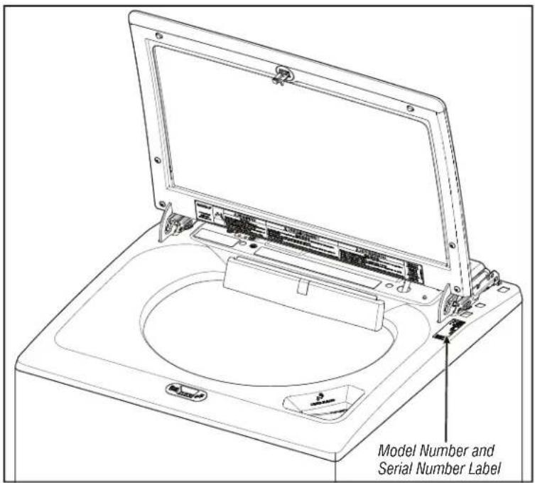
MODEL NUMBER AND SERIAL NUMBER LABEL LOCATION
The Model Number and Serial Number Label location is as shown below:
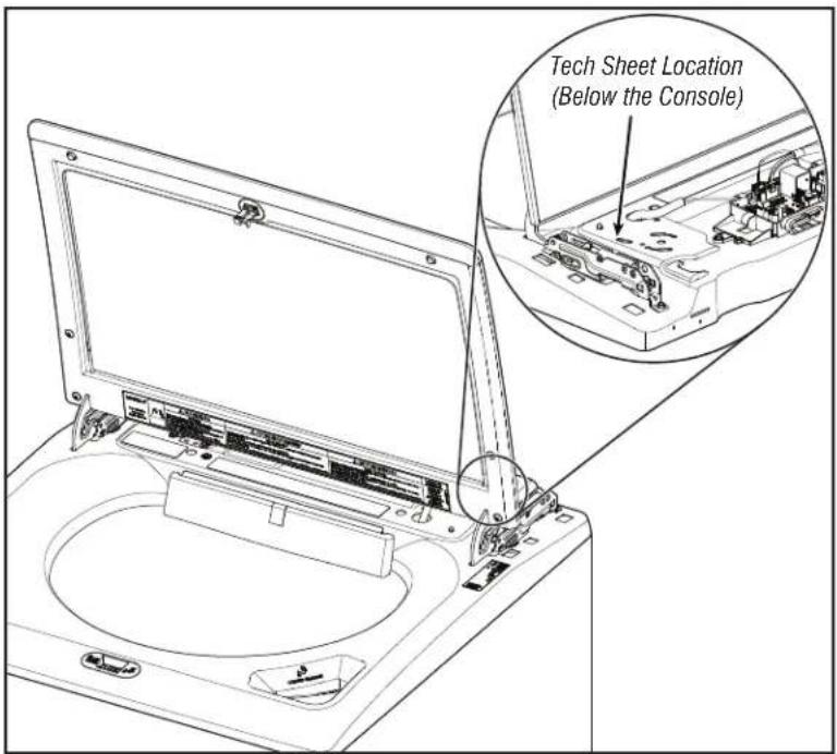
TECH SHEET LOCATION
The Tech Sheet Location is as shown below:
FOR SERVICE TECHNICIAN'S USE ONLY
SERVICE GUIDE
This section (page 10-18) provides general safety, parts, and information for the "Maytag® 4.8 cu. ft. Top Load Washer."
Service Guide
■Activating Service Mode
■Reading Binary codes
■Button Activation & Encoder Test
■Service Test Mode
■Service Test Mode Chart/Component Activation
■Software Version Display
■Diagnostic Cycle Chart
■Faults & Error Codes
SERVICE GUIDE
Before servicing, check the following:
■Make sure there is power at the wall outlet.
■Has a household fuse blown or circuit breaker tripped? Was a regular fuse used? Inform customer that a time-delay fuse is required.
Are both hot and cold water faucets open and water supply hoses unobstructed?
■Make sure drain hose is not sealed into drain pipe, and that there is an air gap for ventilation. Ensure drain height is between 39" (991 mm) and 8' (2.4 m) above the floor.
All tests/checks should be made with a VOM (volt-ohm-milliammeter) or DVM (digital-voltmeter) having a sensitivity of 20,000 Ω per VDC or greater.
■Resistance checks must be made with washer unplugged or power disconnected.
IMPORTANT: Avoid using large diameter probes when checking harness connectors as the probes may damage the connectors upon insertion.
Check all harnesses and connections before replacing components. Look for connectors not fully seated, broken or loose wires and terminals, or wires not pressed into connectors far enough to engage metal barbs.
A potential cause of a control not washer functioning is corrosion or contamination on connections. Use an ohmmeter to check for continuity across suspected connections.
■To properly check voltage:
- Unplug appliance or disconnect power.
- Attach voltage measurement probes to proper connectors.
- Plug in appliance or reconnect power and verify voltage reading.
- Unplug appliance or disconnect power after completing voltage measurements.
DIAGNOSTIC LED - MAIN CONTROL (ACU)
A troubleshooting tool has been implemented onto the main control board—a diagnostic LED.
LED Flashing – The Control is detecting correct incoming line voltage and the processor is functioning.
LED OFF or ON – Control malfunction. Perform TEST #1: Main Control (ACU), to verify main control functionality.
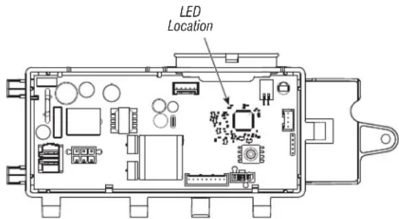
Figure 1 - Diagnostic LED
SERVICE MODE
These tests allow factory or service personnel to test and verify all inputs to the main control board. You may want to do a quick and overall checkup of the washer with these tests before going to specific troubleshooting tests.
ACTIVATING SERVICE MODE
- Be sure the washer is in standby mode (plugged in with all LEDs off).
- Follow the steps below within 8 seconds:
• Press and Release Key 1
• Press and Release Key 2
• Press and Release Key 3
- Repeat this 3 button sequence 2 more times
- If this test mode has been entered successfully, all indicators on the HMI will be illuminated for 1 second then will be turned OFF. After this, if there are no saved fault codes, the STATUS indicators (Sense, Soak, Wash and Done) will blink two times and then all the indicators will be turned OFF.
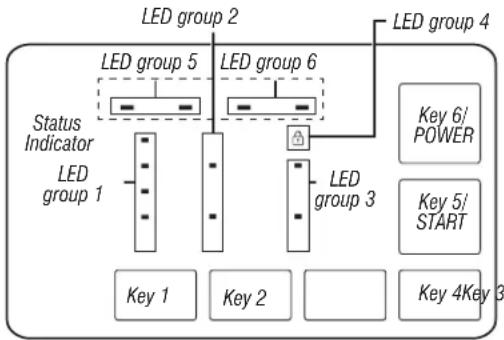
flowchart
graph TD
    A["LED group 1"] --> B["Status Indicator"]
    B --> C["LED group 2"]
    B --> D["LED group 3"]
    B --> E["LED group 4"]
    C --> F["Key 1"]
    D --> G["Key 2"]
    E --> H["Key 4"]
    I["LED group 5"] --> J["LED group 6"]
    K["LED group 3"] --> L["LED group 4"]
    M["Key 6/ POWER"] --> N["LED group 4"]
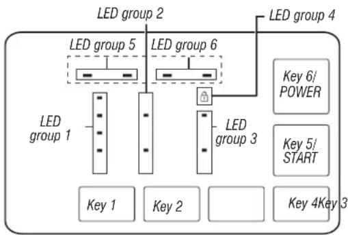
Figure 2: Diagram of the HMI screen and navigational buttons.
Unsuccessful Activation
If entry into Diagnostic mode is unsuccessful, refer to the following indications and actions:
Indication: None of the LEDs will turn on.
Action: Turn on the appliance by pressing the POWER Button or rotating the knob and select any cycle.
LEDs turn on after pressing the POWER Button or turning the knob, then try to enter Service mode again: repeat step 2 mentioned in activating sequence and complete it within 8 seconds. If these re-entry procedures fail to enter into Diagnostic mode, there is likely a faulty button in the HMI. Replace the HMI.
# no LEDs come on after selecting the cycle, go to TEST #1: Main Control (ACU).
Activation with Saved Fault Codes
If there is a saved fault code, it will be flashing in the display. Review the Fault/Error Codes table on page 16 for the recommended procedure. If there is no saved fault code. All LEDs will turn OFF.
FOR SERVICE TECHNICIAN'S USE ONLY
| SERVICE DIAGNOSTIC MENU TABLE | ||
| Button Press Function Behavior | ||
| Key 1 - Momentary press - Enter Button Activation & Encoder test | ||
| - Press and hold for 5 seconds. - Exits Service Diagnostics | ||
| Key 2 - Momentary press - Activates Service Test Mode | ||
| - Press and hold for 5 seconds. - Software Version Display | ||
| Key 3 - Momentary press - Displays Next Error Code | ||
| - Press and hold for 5 seconds. - Clears the Error Codes | ||
- See "Activating Service Diagnostic Mode" to activate these buttons.
READING BINARY CODES
• LED ON means 1
- LED OFF means 0
• The status bar will blink 2x, to display a FxEx code.
- The first LEDs blinking will represent the F-number, and the Lid Lock LED/LED 4 will be ON.
- The Second LEDs blinking will represent the E-number, and the Lid Lock LED/LED 4 will be OFF.
LED group 5 LED group 6
| Value | |
| 0 0 0 0 0 | |
| 0 0 0 1 1 | |
| 0 0 1 0 2 | |
| 0 0 1 1 3 | |
| 0 1 0 0 4 | |
| 0 1 0 1 5 | |
| 0 1 1 0 6 | |
| 0 1 1 1 7 | |
| 1 0 0 0 8 | |
| 1 0 0 1 9 |

Example: F3E2
- Wash and Done are ON
- All are OFF
- Wash is ON
- All are OFF
- Back to step 1
FOR SERVICE TECHNICIAN'S USE ONLY
BUTTON ACTIVATION & ENCODER TEST
NOTE: The Service Diagnostic mode must be activated before entering the Button Activation & Encoder Test; see procedure on page 10.
Entry Procedure
Press and release Key 1 used to activate Service Diagnostic mode. The following test will be available:
DIAGNOSTIC: Button Activation & Encoder Test
The Encoder Test will be active immediately after successfully entering into the Button Activation & Encoder Test:
When the Encoder Test starts, one of the LED from status indicator group will be turned ON.
Rotate the knob CW/CCW from the current position until a full knob rotation is completed. Notice that the LEDs from Status indicator group will turn ON/OFF while the knob is rotated. After the Encoder Test is completed, all the LEDs will be turned ON and the Button Activation test will be active.
Button Activation Test
Pressing each button will toggle ON/OFF its corresponding LEDs:
LED group 1 will toggle ON/OFF with Key 1.
LED group 2 will toggle ON/OFF with Key 2.
LED group 3 will toggle ON/OFF with Key 3.
LED group 4 will toggle ON/OFF with Key 4.
LED group 5 will toggle ON/OFF with Key 5/START.
LED group 6 will toggle ON/OFF with Key 6/POWER.
# LEDs do not toggle ON/OFF after pressing buttons and rotating the cycle selector knob go to TEST: #4 HMI.
Exit Procedure
To exit Button Activation & Encoder test, press and hold Key 1 used to activate Service Diagnostic mode.
SERVICE TEST MODE
NOTE: The Service Diagnostic mode must be activated before entering Service test mode; see procedure on page 10.
NOTE: If, at any point, the user presses the POWER button or opens the door when not requested by the test sequence during Service test mode, the washer exits to standby mode.
NOTE: Door must be closed to perform test.
Active Fault Code Display in Service Test Mode
If the display begins flashing while in Service test mode, it is displaying an active fault code. Active fault codes are codes that are currently detected. Only one active fault code can be displayed at a time.
Entry Procedure
To enter Service test mode, press and release Key 2 used to activate the Service Diagnostic mode then press and release the START button. All LEDs will turn ON indicating that the Service test mode entry was successful.
Perform All Tests: After pressing the START button, the test sequence from page 13 will start.
Exit Procedure
When the test is complete, press the POWER button to exit Service test mode and return to standby mode.
FOR SERVICE TECHNICIAN'S USE ONLY
SERVICE TEST MODE CHART/COMPONENT ACTIVATION
| Step# Action Component HMI response | |||
| 1 | User enters Service test mode through Service Diagnostics by pressing releasing Key 2 used in entry sequence. | Door must be closed. All LEDs are OFF and machine is waiting for the START button to be pressed. | |
| 2 | Press and release the START button to begin the test. Water valves test starts automatically. | Water Valves Test Sequence:Cold Water Valve Opens for 10 seconds or until 70 mm water is filled and then closes.Hot Water Valve Opens for 10 seconds and closes. | Sense LED from Status Indicators is ON during this sequence. |
| 3 | Drain pump test starts automatically.Press Key 1 to repeat the Water Valve test sequence.Press Key 2 to skip the Drain Pump test sequence. | Drain Pump Test Sequence:Drain Pump Turns ON for 45 seconds or till reaching 3 mm water column in the tub. | Soak Phase LED from status indicator is ON during this sequence. |
| 4 | Wash Sequence starts automatically.Press Key 1 to repeat the Drain test sequence.Press Key 2 to skip the wash test sequence. | Wash Test Sequence:Lid Lock closes.Shifter changes its position to wash.Wash action performed for 5 seconds in both CW/CCW.Lid Unlocks. | Wash LED from Status Indicators is ON during this sequence. |
| 5 | Spin Test sequence starts automatically.Press Key 1 to repeat wash test sequence.Press Key 2 to skip spin test sequence. | Spin Test Sequence:Lid Lock closes.Shifter changes its position to spin.Slow spin at 140 rpm for 5 seconds.Medium spin at 300 rpm for 5 secondsFinal spin at 500 rpm for 30 seconds or skip after 25 seconds if 500 rpm not reached.Lid Unlocks after basket speed comes to less than 60 rpm. | Done LED from Status Indicators is ON during this sequence. |
| 6 | End of Service Cycle starts automatically.Press Key 1 to repeat spin test sequence.Press Key 2 to skip water valves test sequence.No key press will take to Service mode. | End of cycle sequence:Shifter turn to wash. | All LEDs from Status Indicators is ON during this sequence. |
FOR SERVICE TECHNICIAN'S USE ONLY
SOFTWARE VERSION DISPLAY
NOTE: The Software Version Display mode will time out after 5 minutes of user inactivity and return to standby mode.
Entry Procedure
To enter Software Version Display, press and hold Key 2 used to activate the Service Diagnostic mode for 5 seconds. Upon entry, the display will automatically cycle through the following information:
| Component Identifier Value | display | |
| ACU Application Firmware 1 | XX:YY:ZZ | |
| HMI Application Firmware 2 | XX:YY:ZZ | |
| Setting File 3 PN1:PN2:PN3 | :PN4:PN5: | PN6:PN7:PN8 |
■Where XX.YY.ZZ corresponds to the 3 sets of 2 digit numbers that describe a software version and PN1.PN2.PN3.PN4.PN5.PN6.PN7.PN8 is the 8 digit settings file part number.
The ACU, HMI and Settings file information will be displayed in the LEDs (SENSE, SOAK, WASH, and DONE) in binary format. Consider SENSE LED the most significant bit.
The identifier value of the component information will be displayed in LED Group1/TEMPERATURE Group in binary format. Consider HOT LED from top as the most significant bit. (For Example: Cold LED blinks, then the Identifier is 1. Cold and Cool LED blinks, then the Identifier is 3).
■LED ON = 1, LED OFF = 0.
Exit Procedure
Pressing the POWER button will exit Software Version Display and return washer to standby mode.
FAULT/ERROR CODES
Refer to service fault/error codes on page 16.
Fault/Error Code Display Method
flowchart
graph TD
    A["LED group 1"] --> B["LED group 2"]
    A --> C["LED group 3"]
    D["LED group 4"] --> E["LED group 5"]
    D --> F["LED group 6"]
    G["Key 1"] --> H["Key 2"]
    I["Key 2"] --> J["Key 3"]
    K["Key 4"] --> L["Key 5"]
    M["Key 6"] --> N["POWER"]
Fault codes are composed by a F# and an E#. The F# has two digits and indicates the suspect System/Category. The E# has two digits and indicates the suspect Component system.
The fault codes are displayed in binary format at the LEDs (SENSE, SOAK, WASH, and DONE). When the LED is ON it represents a binary 1 and when the LED is OFF it represents a binary 0.
Refer to "Reading Binary Codes".
- When the F# digits are displayed, the LID LOCK LED will be turned ON. - When the E# digits are displayed, the LID LOCK LED will be turned OFF. Up to five Fault/Error codes may be stored. Additional presses of Key 3 will cause the system to display the next fault code. If there are no fault codes saved, the LEDs will blink two times for each Key 3 press.
Advancing Through Saved Fault/Error Codes
Procedure for advancing through saved fault codes:
| Press and release Key 3 used to activate service diagnostics | Most recent fault code is displayed. |
| Repeat Second most recent fault code is displayed. | |
| Repeat Third most recent fault code is displayed. | |
| Repeat Fourth most recent fault code is displayed. | |
| Repeat Fifth most recent fault code is displayed. | |
| Repeat Back to the most recent fault code. | |
Clearing Fault Codes
To clear stored fault codes, enter Service Diagnostic mode. Then press and hold Key 3 used to enter Service Diagnostic mode for 5 seconds. Once the stored fault codes are successfully erased, the LEDs will blink two times.
EXITING SERVICE DIAGNOSTIC MODE
Use below method to exit diagnostic mode.
- Pressing the POWER button once.
FOR SERVICE TECHNICIAN'S USE ONLY
DIAGNOSTIC CYCLE CHART
It is recommended to take note of, then clear the Fault History before running the Diagnostic Cycle.
NOTE: The basket must be empty during this test. Some loads will not be available on all models.
| Step | Washer Function Recommended | Procedure Estimated Time (s) | |
| 1 | Warm water fills through the Detergent valve | If no water, use Water Valve test sequence to manually turn on and test the hot and cold water valves. | 60 |
| 2 | Hot water fills through the Detergent valve | If no water, use Water Valve test sequence to manually turn on and test the valve. 5 | |
| 3 | Cold water fills through the Detergent valve | If no water, use Water valve test sequence to manually turn on and test the valve. 5 | |
| 4 | Drain pump turns on | If water is not draining, use Drain Pump test sequence to manually turn on and test the drain pump. | 15 |
| 5 | Lid locks | Lid must be closed. If lid does not lock, use Wash test sequence to manually test the lid lock. | 5 |
| 6 | Shift to Wash Use Wash test sequence to manually test the shifter. 30 | ||
| 7 | Wash Use Wash test sequence to manually test the motor operation in both direction. 5 | ||
| 8 | Shift to Spin Use Spin test sequence to manually test the shifter. 30 | ||
| 9 | Spin up to 500 RPM then stop | Use Spin test sequence to manually test the motor. | 200 |
| 10 | Unlock lid | If lid does not unlock, use service Water valve test sequence to manually test the lid lock. | 5 |
Total test time in minutes is expected to be between 4 - 7 minutes.
Steps 1-3 will display Sense LED. Step 4 will display Soak LED. Steps 5-7 will display Wash LED. Steps 8-10 will display Done LED.
FOR SERVICE TECHNICIAN'S USE ONLY
FAULTS AND ERROR CODES
Faults marked with “‡” will stop the cycle execution. If no action is taken within 5–10 minutes, the display will turn off.
All faults can be viewed in the 'Fault History' section of Service mode.
| Code Description Explanation and Recommended Procedure | ||
| F0E2 Oversuds † | Fault is displayed when suds prevent the basket from spinning up to speed or the pressure sensor detects rising suds level. The main control will flush water in an attempt to clear suds. If the water flush is unable to correct the problem, this may indicate:Not using HE detergent.Excessive detergent usage.Check pressure hose connection from tub to main control. Is hose pinched, kinked, plugged, or leaking air?Mechanical friction on drive mechanism or basket (items between basket and tub). | |
| F0E3 Overload | Fault is displayed when the main control detects a load size that exceeds the washer's capacity OR basket cannot be turned. This may signify:Load size exceeds washer capacity. Remove excess laundry, then restart the cycle.Mechanical friction on drive mechanism or basket (items between basket and tub). | |
| F0E4 | Spin Limited by Water Temperature | Fault is displayed when the water temperature is too high to have spin at final speed. Speed will be limited to 500 RPM.Check water valve function. See TEST #2: Valves. |
| F0E5 Off | Balance Load | Fault is stored when an off balance condition is detected.Check for weak suspension. Basket should not bounce up and down more than once when pushed.Items should be distributed evenly when loading. |
| F0E7 | Load Detected When Running Clean Washer Cycle‡ | Fault is displayed when clothes are detected in the basket when clean washer cycle is selected.Remove any load from the basket before running clean washer cycle. |
| F0E8 Water Ring † | Fault is displayed when too much residual water is detected.Run Drain and Spin Cycle. | |
| F0E9 OB | Pause ‡ | Fault is displayed when an off balance condition is detected and after user interventions.Check for weak suspension. Basket should not bounce up and down more than once when pushed.Items should be distributed evenly when loading. |
| F1E1 Main Control (ACU) Fault ‡ | Fault is displayed indicating a main control (ACU) fault.See TEST #1: Main Control (ACU). | |
| F2E1 HMI Stuck Button | Fault is stored indicating that the user interface is detecting that a button is continuously activated.See TEST #4: HMI. | |
| F2E2 HMI Disconnected ‡ | Fault is displayed if the HMI is disconnected from the ACU.See TEST #4: HMI. | |
| F3E2 Pressure System Fault ‡ | Fault is displayed when the main control detects an out of range or absent pressure signal.Check pressure hose connection from tub to main control. Is hose pinched, kinked, plugged, or leaking air?See TEST #6: Water Level. | |
| F3E3 | Inlet Water Temperature Fault† | Fault is stored when the inlet thermistor is detected to be open or shorted.See TEST #5: Temperature Thermistor. |
| F5E1 | Lid Switch Fault - Lid Is Open† | Fault is displayed if lid is in locked state, but lid switch is open; control not sensing the strike in the lid lock.User presses START with lid open.The main control cannot detect the lid switch opening and closing properly.See TEST #8: Lid Lock. |
FOR SERVICE TECHNICIAN'S USE ONLY
FAULTS AND ERROR CODES
Faults marked with “‡” will stop the cycle execution. If no action is taken within 5–10 minutes, the display will turn off.
All faults can be viewed in the 'Fault History' section of Service mode.
| Code Description Explanation and Recommended Procedure | ||
| F5E3 | Lid Lock Will Not Unlock‡ | Fault is displayed when one of the following conditions occurs:Excessive force on lid is preventing lock bolt from retracting.Wash media buildup is preventing lock bolt from retracting.Main control cannot determine if lid lock is in an unlocked state.See TEST #8: Lid Lock. |
| Lid Lock Will Not Lock† | Fault is displayed when one of the following conditions occurs:Check lid lock for obstructions.See TEST #8: Lid Lock. | |
| F5E4 | Lid Not Opened Between Cycles† | Fault is displayed when one of the following conditions occurs:User presses START with lid open.User presses START after a predetermined number of consecutive washer cycles without opening lid.The main control cannot detect the lid switch opening and closing properly.See TEST #8: Lid Lock. |
| F6E1 | Communication Error: HMI Cannot Hear ACU† | Fault is displayed when communication between the HMI and the ACU has not been detected.Check continuity in the HMI harness.CompleteTEST #1: Main Control (ACU) andTEST: #4 HMI. |
| F7E1 | Tachometer missing or Wrong Signal† | Fault is stored when the ACU cannot read the speed or power from the tachometer.Check connections to the ACU.CompleteTEST #1: Main Control (ACU).Complete Sensor Feedback Motor Speed Tachometer test. |
| F7E3 | Basket Engaged During Wash | Fault is stored when the main control determines the shifter is not engaging the basket for spin or disengaging it for wash.Check shifter connectors.Check for clothing or another item wedged between the impeller and the basket that could bind them together.Check that the shifter slider moves freely.SeeTEST #3a: Drive System – Shifter. |
| F7E4 | Basket Re-engagement Failure | |
| F7E6 Motor Circuit Open | Fault is stored when main control detects one or more of the motor lines is open.Check motor circuit.SeeTEST #1: Main Control (ACU),TEST #3: Drive SystemorTEST #3b: Drive System – Motor. | |
| F7E7 | Motor unable to reach target RPM | Fault is stored when motor cannot reach the target RPM.Check basket for obstructions.SeeTEST #1: Main Control (ACU),TEST #3b: Drive System – Motor. |
| F8E1 Long Fill ‡ | Fault is displayed when the water level does not change for a period of time OR water is present but the control does not detect the water level changing.Is water supply connected and turned on?Are hose screens plugged?Is water siphoning out of the drain hose?Check for proper drain hose installation.Low water pressure; fill times longer than 10 minutes.Is the pressure hose connection from the tub to the main control pinched, kinked, plugged, or leaking air?SeeTEST #2: ValvesandTEST #6: Water Level. | |
FOR SERVICE TECHNICIAN'S USE ONLY
FAULTS AND ERROR CODES
Faults marked with “‡” will stop the cycle execution. If no action is taken within 5–10 minutes, the display will turn off.
All faults can be viewed in the 'Fault History' section of Service mode.
| Code | Description Explanation and | Recommended Procedure |
| F8E3 | Overflow or Flood Condition ‡ | Fault is displayed when main control senses water level that exceeds washer capacity.Check pressure hose connection from tub to main control. Is hose pinched, kinked, plugged, or leaking air?Check for proper drain hose installation. Is water siphoning out of the drain hose? Drain hose must not be more than 4.5" (114 mm) into the drain pipe. Make sure drain hose is not sealed into drain pipe, and that there is an air gap for ventilation. Ensure that drain height is between 39" (991 mm) and 8' (2.4 m) above the floor.May signify problem with water inlet valves.Pressure transducer fault on main control.SeeTEST #2: Valves and TEST #6: Water Level. |
| F8E6 | Water Hazard † | Fault is displayed when main control senses water in the tub and the lid has been left open for more than 10 minutes.Check pressure hose connection from tub to main control. Is hose pinched, kinked, plugged, or leaking air?Check for proper drain hose installation. Is water siphoning out of the drain hose? Drain hose must not be more than 4.5" (114 mm) into the drain pipe. Make sure drain hose is not sealed into drain pipe, and that there is an air gap for ventilation. Ensure that drain height is between 39" (981 mm) and 8' (2.4 m) above the floor.May signify problem with water inlet valves.Pressure transducer fault on main control.May signify problem with lid lock.SeeTEST #2: Valves, TEST #6: Water Level, or TEST #8: Lid Lock. |
| F9E1 | Drain Pump System Problem - Long Drain† | Fault is displayed when the water level does not change after the drain pump is on.Is the drain hose or the drain pump clogged?Is the drain hose height greater than 8' (2.4 m)?Is the pressure hose connection from the tub to the main control pinched, kinked, plugged, or leaking air?Too much detergent.Is the pump running? If not, seeTEST #7: Drain Pump. |
FOR SERVICE TECHNICIAN'S USE ONLY
TROUBLESHOOTING
This section (page 20-28) provides general safety, parts, and information for the "Maytag® 4.8 cu. ft. Top Load Washer."
Troubleshooting Guide
■Main Control (ACU) Board Connectors and Pinouts
Troubleshooting Tests
■Component Locations
FOR SERVICE TECHNICIAN'S USE ONLY
TROUBLESHOOTING GUIDE
NOTE: Always check for Faults and Error Codes first. Some tests will require accessing components.
See figures. 7 & 8 for Component Locations. For detailed troubleshooting procedures, refer to "Troubleshooting Tests."
| Problem Possible | Cause Checks & Tests | |
| Won't Power UpNo operationNo keypad responseNo LEDs or display | No power to washer.Connections between main control and HMI. | Check power at outlet, check circuit breakers, fuses, or junction box connections. |
| Connection problem between AC plug and main control. | Check the AC power cord for continuity. | |
| User Interface problem. Check connections and continuity between main control and HMI. See TEST #4: HMI. | ||
| Main Control problem. See TEST #1: Main Control (ACU). | ||
| Won't Start CycleNo response when START is pressed | Lid lock mechanism not functioning. | 1. Lid not closed due to interference.2. Lock not closed due to interference.3. See TEST #8: Lid Lock. |
| Connections between main control and HMI. Check connections and continuity between main control and HMI. | ||
| User Interface problem. See TEST #4: HMI. | _ | |
| Main Control problem. See TEST #1: Main Control (ACU). | ||
| HMI Won't Accept Selections | Connections between main control and HMI. Check connections and continuity between main control and HMI. | |
| User Interface problem. See TEST #4: HMI. | _ | |
| Main Control problem. See TEST #1: Main Control (ACU). | ||
| Won't Fill | No water supplied to washer. 1. Check water connections to washer.2. Verify that hot and cold water supply is on. | |
| Plugged filter/screen. | Check for plugged filter or screen in the water valve or hoses. | |
| Drain hose installation. Check for proper drain hose installation. | ||
| Valve problem. | See TEST #2: Valves. | |
| Main Control problem. See TEST #1: Main Control (ACU). | ||
| Overfills | Pressure hose. | See TEST #6: Water Level. |
| Valve problem. | See TEST #2: Valves. | |
| Washer requires calibration. | Perform Service Calibration. | |
| Pressure transducer on main control. | See TEST #1: Main Control (ACU). | |
| Won't Dispense Fabric Softener Or Oxi (Oxi not on all models) | No water supplied to washer. 1. Check water connections to washer.2. Verify that hot and cold water supply is on. | |
| Obstruction in dispenser. | Clean obstruction from dispenser. | |
| Valve problem. | See TEST #2: Valves. | |
| Main Control problem. See TEST #1: Main Control (ACU). | ||
FOR SERVICE TECHNICIAN'S USE ONLY
TROUBLESHOOTING GUIDE
NOTE: Always check for Faults and Error Codes first. Some tests will require accessing components.
See figures. 7 & 8 for Component Locations. For detailed troubleshooting procedures, refer to "Troubleshooting Tests."
| Problem Possible | Cause Checks & Tests | |
| Incorrect Water Temperature | Water hose installation. Make sure inlet hoses are connected properly. | |
| Temperature thermistor. See TEST #5: Temperature Thermistor. | ||
| Valve problem. See TEST #2: Valves. | ||
| Main Control problem. See TEST #1: Main Control (ACU). | ||
| Won't Agitate | Water covering the impeller? See TEST #6: Water Level. | |
| Is lid lock showing open during the cycle? See TEST #8: Lid Lock. | ||
| Harness connections. Check harness connections between main control and drive system. | ||
| Shifter problem. See TEST #3a: Drive System - Shifter. | ||
| Motor problem. See TEST #3b: Drive System - Motor. | ||
| Main Control problem. See TEST #1: Main Control (ACU). | ||
| Won't Spin | Is lid lock showing open during the cycle? | See TEST #8: Lid Lock. |
| Harness connections. Check harness connections between main control and drive system. | ||
| Shifter problem. See TEST #3a: Drive System - Shifter. | ||
| Motor problem. See TEST #3b: Drive System - Motor. | ||
| Main Control problem. See TEST #1: Main Control (ACU). | ||
| Won't Drain` | Drain hose installation. | Check for proper drain hose installation. Make sure it is not inserted more than 4.5" (114 mm). Make sure drain hose is not sealed into drain pipe, and that there is an air gap for ventilation. |
| Standpipe position. | Ensure drain height is between 39" (991 mm) and 8" (2.4 m) above the floor. | |
| Plugged drain hose. | Check drain hose for obstructions. | |
| Obstructions to drain pump. | Check tub sump under impeller plate & basket for obstructions. | |
| Harness connections. Check harness connections between main control and drain pump. | ||
| Drain pump. | See TEST #7: Drain Pump. | |
| Main Control problem. | See TEST #1: Main Control (ACU). | |
| Cycle Time Longer Than Expected | Oversuds. | 1. Verify use of HE detergent.2. Excessive detergent usage. |
| Off balance. | 1. Load is off balance.2. Balance ring water leak. | |
| Drain hose installation. | Check for proper drain hose installation. Make sure it is not inserted more than 4.5" (114 mm). Make sure drain hose is not sealed into drain pipe, and that there is an air gap for ventilation. | |
| Standpipe position. | Ensure drain height is between 39" (991 mm) and 8' (2.4 m) above the floor. | |
| Draining slowly. | Check for pump or drain hose obstructions. | |
| Water pressure drop. | Results in longer fill time. | |
| Friction or drag on drive. | Check motor and bearings; check for items between tub and basket. | |
| Weak suspension. | Basket should not bounce up and down more than once when pushed. | |
FOR SERVICE TECHNICIAN'S USE ONLY
TROUBLESHOOTING GUIDE
NOTE: Always check for Faults and Error Codes first. Some tests will require accessing components.
See figures. 7 & 8 for Component Locations. For detailed troubleshooting procedures, refer to "Troubleshooting Tests."
| Problem Possible | Cause Checks & Tests | |
| Poor Wash PerformancePlease see “Quick Reference Guide” | Oversuds. 1. Verify use of HE detergent. | 2. Excessive detergent usage. |
| Load is Tangling. 1. Washer not loaded properly. | 2. Perform Service Calibration. | |
| Incorrect water level. 1. Perform Service Calibration. | 2. See TEST #2: Valves.3. See TEST #6: Water Level. | |
| Clothes wet after cycle is complete (not water saturated, but very damp). | 1. Overloaded washer.2. Oversuds (see above).3. Items caught in tub sump.4. Weak suspension.5. Shifter not moving into position.6. Cold/Rinse water > 105°F (40.5°C).7. See TEST #7: Drain Pump.8. See TEST #3b: Drive System – Motor. | |
| Load not rinsed. 1. Check proper water supply. | 2. Not using HE detergent.3. Washer not loaded properly.4. Shifter not moving into spin position.5. See TEST #2: Valves.6. See TEST #3b: Drive System – Motor. | |
| Not cleaning clothes. 1. Washer not loaded properly. | 2. Not using HE detergent.3. Not using correct cycle.4. Shifter not moving into position.5. See TEST #3b: Drive System – Motor. | |
| Fabric damage. 1. Washer overloaded. | 2. Bleach added incorrectly.3. Sharp items in tub. | |
| Wrong option or cycle selection. Refer customer to | “Quick Reference Guide”. |
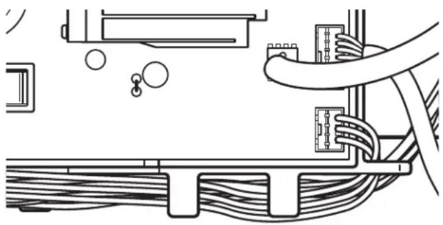
Troubleshooting Pinched Wires in the Harness
natural_image
Diagram of a cable connection setup with wires and connectors (no text or labels)Figure 3 - Troubleshooting pinched wires in Harness
IMPORTANT: Verify that the harness is routed under the guides in the main control (ACU) as shown above before re-installing the console.
MAIN CONTROL (ACU) BOARD CONNECTORS AND PINOUTS
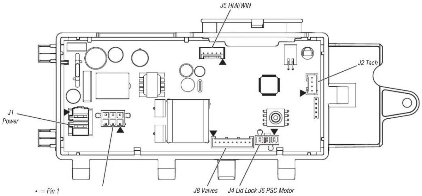
Figure 4 - Main Control (ACU)
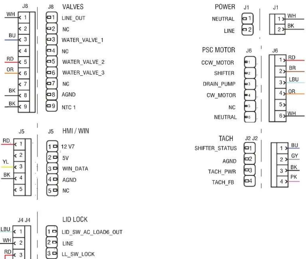
Figure 5 - Connector and Pinouts
TROUBLESHOOTING TESTS
TEST #1: Main Control (ACU)
This test checks for incoming and outgoing power to and from main control. This test assumes that proper voltage is present at the outlet.
- Unplug washer or disconnect power.
- Remove console to access main control.
- Verify that all connectors are inserted all the way into the main control.
-
With a voltmeter set to AC, connect black probe to J1-1 (Neutral) and red probe to J1-2 (Line). Plug in washer or reconnect power.
120 VAC is present, go to step 5.
120 VAC is not present, check the AC power cord for continuity (See Figure 7.) -
Is the "Diagnostic LED" flashing or continuously "ON" or "OFF"? See Figure 1 for LED location).
Flashing: (+5 VDC present and micro operating) proceed to HMI Test.
ON: (+5 VDC but micro failure) continue to step 8.
OFF: (+5 VDC missing or micro failure) continue to step 6. -
Check if console HMI is affecting the main control DC supply.
a. Unplug washer or disconnect power.
b. Remove connector J5 from main control.
c. Plug in washer or reconnect power.
- Perform voltage checks inside header J5 on the board – do not short pins together.
a. With a voltmeter set to DC, connect black probe to J5-4 (Circuit Gnd) and red probe to J5-1 (+12 VDC).
DC voltage is not present, go to step 8.
the DC voltage is present, but the diagnostic LED is not flashing, continue to step 8.
- Main Control has malfunctioned.
a. Unplug washer or disconnect power.
b. Replace the main control.
c. Reassemble all parts and panels.
d. Plug in washer or reconnect power. Perform Service Diagnostic cycle to verify repair.
TEST #2: Valves
This test checks the electrical connections to the valves, and the valves themselves.
-
Check the relays and electrical connections to the valves by performing Water Valve test sequence under Component Activation. Each test activates and deactivates the selected valve. The following steps assume one (or more) valve(s) did not turn on.
-
For the valve(s) in question check the individual solenoid valves.
a. Unplug washer or disconnect power.
b. Remove console to access main control.
c. Remove connector J8 from main control. Refer to Figure 7 - Main Control.
d. Check harness continuity and connection to solenoid valves.
- Check resistance of the valve coils across the following J8 connector pinouts:
| Valve Pinout | |
| Fabric Softener J8, 1 & 6 | |
| Hot J8, 1 & 5 | |
| Cold J8, 1 & 3 |
Resistance should be 890–1090 Ω.
resistance readings are tens of ohms outside of range, replace the valve assembly.
# resistance readings are within range, replace main control and perform Service Diagnostics to verify repair.
TEST #3: Drive System
- Enter Service mode and view Fault Codes. If F7E1, F7E3, F7E4, F7E6 or F7E7 faults are shown then there is likely a motor or shifter related issue Take note of the faults and clear the faults.
- Once the error codes are cleared, enter Component Activation mode and run the Slow Agitation test; if the motor runs after 15–20 seconds, there is not a problem with the motor, control, or motor wiring harness connections.
- Next, within Component Activation mode, run the Spin Low Speed cycle. If the motor hums briefly and then shuts down, go to Fault Code display mode and check for fault codes.
- After running agitation and spin test, check for fault codes.
TEST #3a: Drive System – Shifter
This test checks connections, shifter coil, and harness.
NOTE: Lid must be closed and locked for the motor to agitate or spin.
IMPORTANT: Drain water from tub before accessing bottom of washer.
Functional Check:
- Check the shifter and electrical connections by performing both the Spin and Wash test under Component Activation Mode. The following steps assume that this step was unsuccessful.
- Unplug washer or disconnect power.
- The motor and shifter should be able to be turned independently of each other. If they are locked together, there is a shifter slider issue. Proceed to step 11.
basket and impeller turn freely, go to step 4.
¶ basket and/or impeller do not turn freely, determine what is causing the mechanical friction or lockup.
4. Remove console to access main control.
5. Visually check that the J2 and J6 connectors are inserted all the way into the main control.
visual checks pass, go to step 6.
connector is not inserted properly, reconnect J2 and J6 and repeat step 1.
Shifter Motor:
NOTE: Before starting the electrical check, verify that the cam on the splutch is moving freely and not binding.
FOR SERVICE TECHNICIAN'S USE ONLY
- Remove connector J6 from main control. With an ohmmeter, verify resistance of the shifter motor across the following J6 connector pinouts:
Resistance should be 2 kΩ to 3.5 kΩ.
Component J6 Connector Pinout
Shifter J6, 2 & 6
values are correct, reconnect J6 and proceed to step 7.
values are open or out of range, go to step 12.
- With a voltmeter set to AC, connect the black probe to J6-2 and red probe to J6-6. Plug in washer or reconnect power. Activate shifter motor by switching the shifter output ON and OFF. Energize outputs using Component Activation mode.
NOTE: Motor must be stopped to toggle the shifter. Alternately, Spin and Agitate can be commanded to switch shifter in Component Activation mode.
IMPORTANT: Lid must be closed to run the Spin and Wash tests.
120 VAC is present, go to step 8.
120 VAC is not present, go to step 11.
Shifter Switch:
- With a voltmeter set to DC, connect the black probe to J2-2 (Circuit Gnd) and red probe to J2-1 (Shifter Switch). In Component Activation mode, switch between Spin and Agitate modes. Voltage should toggle between 0 and +5 VDC.
SPIN = +5 VDC
AGITATE = 0 VDC
if voltage corresponds to setting, go to step 9.
If voltage does not switch, go to step 11.
Optical Sensor:
- With a voltmeter set to DC, connect the black probe to J2-2 (Circuit Gnd) and a red probe to J2-3 (Tach Pwr).
+12 VDC is present, go to step 10.
+12 VDC is not present, go to step 16. - Activate Motor Speed Tachometer from Sensor Feedback. Slowly turn the basket by hand.
NOTE: Spinning the basket too fast will result in a safety fault for the lid lock. The screen will display the basket speed in RPM.
the tachometer is not verified, go to step 11.
the tachometer is verified, go to step 16. - Unplug washer or disconnect power.
- Tilt washer back to access the bottom of the washer and the drive motor area.
- Visually check the electrical connections to the shifter.
visual check passes, go to step 14.
If connections are loose, reconnect the electrical connections and repeat step 1.
14. With an ohmmeter, check the harness for continuity between the shifter and main control using the pinouts in the following chart.
if there is continuity, go to step 15.
there is no continuity, replace the lower washer harness and repeat step 1.
Shifter to Main Control & Drain Pump
| Shifter Pin 1 to Main Control J2-4 |
| Shifter Pin 2 to Main Control J2-3 |
| Shifter Pin 3 to Main Control J6-6 |
| Shifter Pin 4 to Main Control J2-1 |
| Shifter Pin 5 to Main Control J2-2 |
| Shifter Pin 6 to Main Control J6-2 |
- Replace the shifter assembly.
a. Unplug washer or disconnect power.
b. Replace shifter assembly.
c. Reassemble all parts and panels.
d. Plug in washer or reconnect power. Calibrate washer and perform Automatic Test to verify repair.
- If the preceding steps did not correct the problem, replace the main control.
a. Unplug washer or disconnect power.
b. Replace the main control.
c. Reassemble all parts and panels.
d. Plug in washer or reconnect power. Calibrate washer and perform Automatic Test to verify repair.
TEST #3b: Drive System – Motor
This test checks the motor, motor windings, wiring, and start capacitor.
IMPORTANT: Drain water from tub before accessing bottom of washer.
- Check the motor and electrical connections by performing the wash test sequence under Component Activation. Verify that the basket is spinning in a clockwise direction while performing Low, Mid or High Spin Speed test under Component Activation. The following steps assume that this step was unsuccessful.
- Unplug washer or disconnect power.
- Check to see if basket will turn freely.
# basket turns freely, go to step 4.
basket does not turn freely, determine what is causing the mechanical friction or lockup.
- Remove console to access main control.
- Visually check that the J2 and J6 connectors are inserted all the way into the main control.
# visual checks pass, go to step 6.
# visual checks fail, reconnect connectors and repeat step 1.
- Plug in washer or reconnect power. Run the Motor Slow Wash test under Component Activation.
- With a voltmeter set to AC, connect black probe to J6-6 (Neutral) and red probe to J6-4 (CW Winding).
120 VAC is cycling ON during CW rotation, go to step 8.
120 VAC is not present, go to TEST #1: Main Control (ACU).
- With a voltmeter set to AC, connect black probe to J10-6 (Neutral), red probe to J6-1 (CCW Winding).
120 VAC is cycling ON during CCW rotation, go to step 9.
120 VAC is not present, go to TEST #1: Main Control (ACU).
-
Unplug washer or disconnect power.
-
Remove connector J6 from main control. With an ohmmeter, check resistance of motor windings across the following J6 connector pinouts:
| Motor Winding J10 | Pinout Resistance | |
| CW Winding J6, 4 | & 6 5-9.5 Ω | |
| CCW Winding J6, 1 | & 6 5-9.5 Ω |
# values are open or out of range, go to step 11.
# values are correct, go to step 15.
- Tilt washer back to access drive system.
FOR SERVICE TECHNICIAN'S USE ONLY
- Visually check the mounting bracket and electrical connections to the motor and shifter.
visual check passes, go to step 13.
connections are loose, reconnect the electrical connections, reassemble motor cover, and repeat step 1.
- With an ohmmeter, check the harness for continuity between the main control, motor, and run capacitor using the following test points.
Motor Harness Check
| Motor Connector Pin-1 to Chassis GND |
| Motor Connector Pin-4 to Main Control J6-1Motor Connector Pin-4 to Motor Capacitor Pin 1 |
| Motor Connector Pin-3 to Main Control J6-4Motor Connector Pin-3 to Motor Capacitor Pin 3 |
| Motor Connector Pin-2 to Main Control J6-6 |
where is continuity, go to step 14.
where is no continuity, replace the lower machine harness and repeat step 1.
- With an ohmmeter, check resistance of motor windings at the following motor connections.
| Motor Winding Pin | put Resistance | |
| CW Winding Pins | 3 & 2 5-9.5 Ω | |
| CCW Winding Pins | 4 & 2 5-9.5 Ω |
# values are open or out of range, replace motor.
# values are correct, go to step 15.
- Test Motor Run Capacitor.
NOTE: A faulty capacitor may cause the motor to "hum", not start, or turn slowly.
a. Discharge the capacitor by touching the leads of a 20,000 Ω resistor to the two terminals.
b. Disconnect the wires from the capacitor terminals.
c. With an ohmmeter, measure across the terminals and note reading. If a steady increase in resistance is noted, continue to step 16.
The capacitor is either shorted or open, replace capacitor, calibrate, and repeat step 1.
- If the preceding steps did not correct the motor problem, replace the main control.
a. Unplug washer or disconnect power.
b. Replace the main control.
c. Reassemble all parts and panels.
d. Plug in washer or reconnect power. Calibrate washer and perform the Diagnostic Cycle or Component Activation to verify repair.
TEST #4: HMI
Conduct each test within HMI test in Service mode including Key, LED, and Encoder Tests. This procedure is performed when any of the following situations occurs during the HMI Tests.
Key presses do not display correctly on the HMI.
The LED group indicators doesn't lit up.
Encoder turns do not display correctly on the HMI.
- Unplug washer or disconnect power.
-
Access the console's electronic assemblies and visually check that the J5 connector is inserted all the way into the main control and that the HMI harness connector is fully seated on the HMI. Ensure the ribbon cables are properly connected on both ends.
-
If both visual checks pass, follow procedure under TEST #1: Main Control (ACU) to verify supply voltages.
- Verify the continuity of the HMI harness.
| ACU PIN Color HMI PIN | ||
| J5-1 Red J1-1 | ||
| J5-3 Yellow J1-2 | ||
| J5-4 | Black | J1-3 |
# continuity fails, replace the HMI harness and go to step 5.
# continuity passes, replace the user interface and go to step 5.
- Reassemble all parts and panels.
- Plug in washer or reconnect power.
- To verify repair, activate the Service mode, and then perform HMI test.
TEST #5: Temperature Thermistor
This test checks valves, main control, temperature thermistor, and wiring.
- Check the thermistor by performing the Inlet Thermistor test under Sensor Feedback mode in Service mode on page 10.
- The screen will display the inlet thermistor temperature in degrees Celsius. The cold valve will open and the displayed temperature will drop. Then the hot valve will open and the displayed temperature will increase.
the machine operates as expected then the thermistor is operating correctly.
The temperature increases first then decreases, check the hose connections and repeat.
The displayed temperature does not act as described then proceed to step 3.
- Unplug washer or disconnect power.
- Remove console to access main control.
- Remove connector J8 from the main control. With an ohmmeter, measure the resistance of the temperature thermistor between pins J8-9 and J8-8. Verify that the approximate resistance, shown in the table below, is within ambient temperature range.
THERMISTOR RESISTANCE
| Approx. Temperature | Approximate Resistance | |
| °F | °C | kΩ |
| 32 0 | 163 | |
| 41 5 | 127 | |
| 50 | 10 | 100 |
| 59 | 15 | 79 |
| 68 | 20 | 62 |
| 77 | 25 | 50 |
| 86 | 30 | 40 |
| 95 | 35 | 33 |
| 104 40 | 27 | |
| 113 45 | 22 | |
| 122 50 | 18 | |
| 131 55 | 15 | |
| 140 60 | 12 | |
| 149 65 | 10 | |
FOR SERVICE TECHNICIAN'S USE ONLY
the resistance is within the range shown in the table, go to step 6.
the resistance is infinite or close to zero, replace the valve assembly.
NOTE: Most thermistor errors are a result of the resistance being out of range. If the temperature thermistor malfunctions, the washer will default to pre-programmed wash settings.
- If the thermistor is good, replace main control and perform step 1 again to verify repair.
TEST #6: Water Level
This test checks the water level sensing components.
NOTE: Usually, if the pressure transducer malfunctions, the washer will generate a long fill, or long drain error (F8E1 or F9E1).
- Check the functionality of the pressure transducer by running by running the Water Level Pressure Sensor cycle within Service Sensor Feedback.
- Verify that the valves open and the basket begins to fill. The screen should display the water level rising as the basket fills, then decreasing as the basket drains.
NOTE: The water level in the basket might not raise high enough to be visible but that is normal. - If step 2 behaves correctly skip to step 9, otherwise continue to step 4.
- Unplug washer or disconnect power.
- Remove console to access main control.
- Check hose connection between the pressure transducer on the main control and the pressure dome attached to the tub.
- Check to ensure hose is routed correctly in the lower cabinet and not pinched or crimped inside the console or by the back panel.
- Verify there is no water, suds, or debris in the hose or dome. Disconnect hose from main control and blow into hose to clear water, suds, or debris.
- Check hose for leaks. Replace if needed.
- If the preceding steps did not correct the problem, replace main control and perform Service Diagnostics. Run Water Level Pressure Sensor cycle within Service Sensor Feedback to verify.
TEST #7: Drain Pump
Perform the following checks if washer does not drain.
IMPORTANT: Drain water from tub before accessing the bottom of the washer.
- Check for obstructions in the usual areas. Clean and then perform step 2.
-
Check the drain pump and electrical connections by turning on the drain pump in Service Component Activation mode. The following steps assume that this step was unsuccessful.
-
Unplug washer or disconnect power.
-
Remove console to access main control.
-
Visually check that the J6 connector is inserted all the way into the main control.
# visual check passes, go to step 6.
connector is not inserted properly, reconnect J6 and repeat step 2.
- Remove connector J6 from main control. With an ohmmeter, verify resistance values shown below across the following J6 connector pinouts:
Component J15 Pinout Resistance
| Drain Pump J6, 3 & 6 17.8-21.8 Ω |
# values are open or out of range, go to step 7.
If values are correct, go to step 11.
-
Tilt washer back to access drain pump. Verify pump is free from obstructions.
-
Visually check the electrical connections at the drain pump.
# visual check passes, go to step 9.
connections are loose, reconnect the electrical connections and repeat step 2.
- With an ohmmeter, check harness for continuity between the drain pump and main control. See chart below:
Main Control to Drain Pump
| Drain Pump Pin 1 to Main Control J6-3 (Lt. Blue Wire) |
| Drain Pump Pin 3 to Main Control J6-6 (White Wire) |
where is continuity, go to step 10.
If there is no continuity, replace the lower washer harness and repeat step 2.
- With an ohmmeter, measure the resistance across the two pump terminals. Resistance should be as shown in the chart below:
Component Resistance
| Drain Pump 17.8-21.8 Ω |
# values are open or out of range, replace the pump motor.
the resistance at the pump motor is correct, go to step 11.
- If the preceding steps did not correct the drain problem, replace the main control.
a. Unplug washer or disconnect power.
b. Replace the main control.
c. Reassemble all parts and panels.
d. Plug in washer or reconnect power. Perform Service Diagnostics to verify repair.
TEST #8: Lid Lock
Perform the following checks if the washer does not lock (or unlock).
- Check the lid lock by performing Lid Lock test under Service Load Control mode in Service Diagnostic mode. The following steps assume that this step was unsuccessful.
- Unplug washer or disconnect power.
- Remove console to access main control.
- Visually check that the J4 connector is inserted all the way into the main control.
# visual check passes, go to step 5.
connector is not inserted properly, reconnect J4 and repeat step 1.
- Check the lid lock motor winding and switches by removing J4 from the main control and checking the resistance values shown in the following table:
LID LOCK RESISTANCE
| Component Resistance Contacts Measured | |||
| Lock Switch Solenoid | 50-160 Ω J4-2 J4-3 | ||
| Lock Switch | Locked = 0 ΩUnlocked = Open | J4-1 J4-2 | |
| Lid Switch | Lid Open = Open Circuit | J4-2 J4-1 | |
# resistance values are good, go to step 6.
If switch measurements do not match the values shown in the table for unlocked (or locked) condition, a problem exists in the lid lock. Replace the lid lock mechanism.
NOTE: Ensure that the protective corrugated tubing passes through the hole in the top and that the push mount clip is connected to the top from below. Additionally, route the lid lock wires through the retaining clips on the ACU.
FOR SERVICE TECHNICIAN'S USE ONLY
- If the preceding steps did not correct the lock problem, replace the main control.
a. Unplug washer or disconnect power.
b. Replace the main control.
c. Reassemble all parts and panels.
d. Plug in washer or reconnect power. Perform Service Diagnostics to verify repair.
COMPONENT LOCATIONS
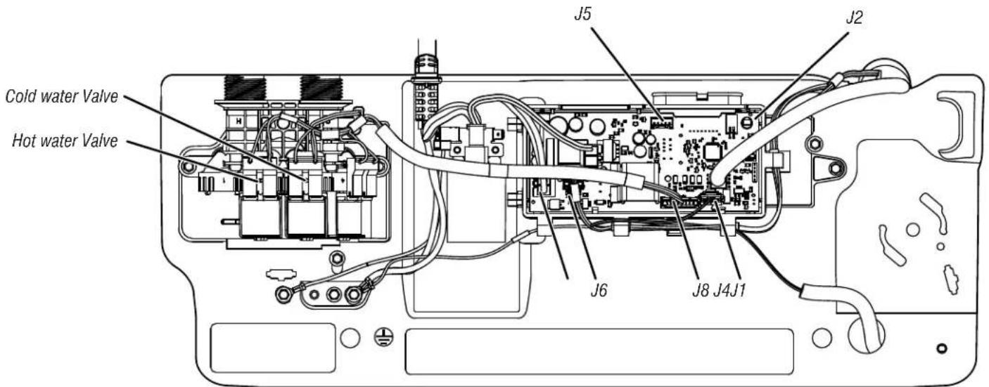
Figure 7 - Main Control (ACU)
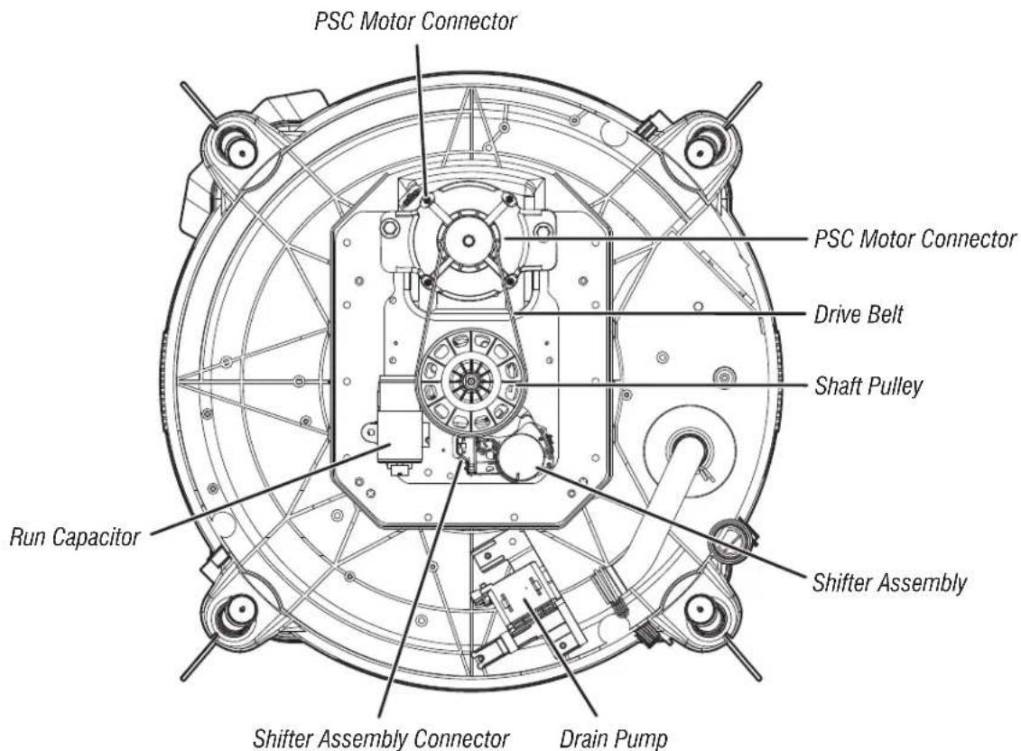
Figure 8 - Bottom View - PSC
FOR SERVICE TECHNICIAN'S USE ONLY
COMPONENT ACCESS
This section (page 28-41) provides service parts access, removal, and replacement instructions for the "Maytag ^® 4.8 cu. ft. Top Load Washer."
■Removing the Console
■Removing the User Interface (UI)
■Removing the Water Inlet Valve
■Removing the Main Control
■Removing the Bulk Dispenser
■Removing the Tub Ring, Impeller, and Basket
■Removing the Lid Lock
■Removing the Lid and Hinge
■Removing the Shifter
■Removing the Drain Pump
■Removing the Drive Belt and Motor
■Removing the Splutch
■Removing the Gearcase
FOR SERVICE TECHNICIAN'S USE ONLY
Removing the Console
WARNING
Electrical Shock Hazard
Disconnect power before servicing.
Replace all parts and panels before operating.
Failure to do so can result in death or electrical shock.
- Unplug washer or disconnect power.
- Turn off the water supply to the washer.
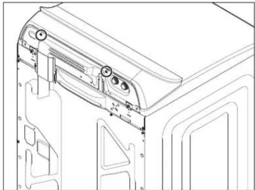
- Remove two (2) 1/4" (6 mm) hex-head/TORX ^+ T20 screws from the rear of the console.
natural_image
Technical line drawing of a mechanical assembly with mounting brackets and internal components (no text or symbols)- Raise the Lid.
- While pushing back and up on the console, slide thin plastic putty knife (or thin plastic cake knife) between the console and Top Panel.
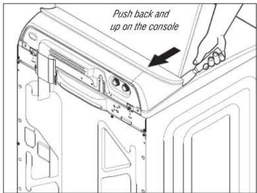
- Depress the console clip by pushing straight back with the putty knife while lifting the console to separate from the Top Panel.
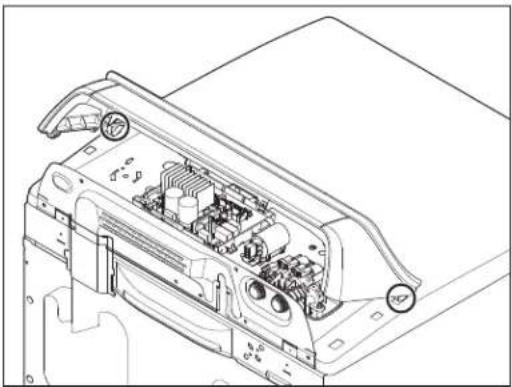
natural_image
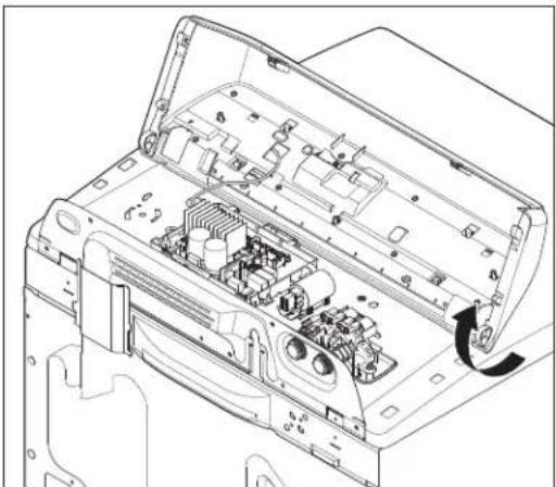
Technical line drawing of an internal electronic device casing with visible circuitry and ports (no text or labels)- Close the lid.
- Tilt console forward to access.
natural_image
Technical line drawing of an open electronic device casing with internal components and a curved arrow indicating rotation (no text or symbols)†®Torx is a registered trademark of Acument Intellectual Properties, LLC.
Removing the User Interface (UI)
WARNING
Electrical Shock Hazard
Disconnect power before servicing.
Replace all parts and panels before operating.
Failure to do so can result in death or electrical shock.
- Unplug washer or disconnect power.
- Complete the steps 1-8 from section Removing the Console.
- Disconnect the 3-wire UI harness from the ACU by depressing the tab and lifting it.
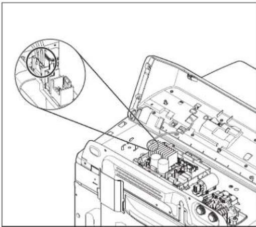
natural_image
Technical line drawing of an open electronic device with internal components and a magnified inset showing internal structure (no text or symbols)- Remove the eight (8) 1/4" (6 mm) hex-head screws securing the UI to the console.
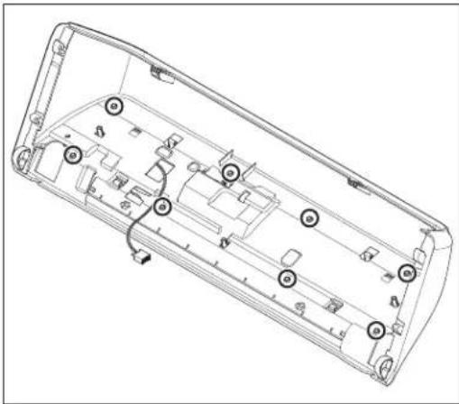
natural_image
Technical line drawing of a rectangular electronic device casing with internal components and mounting holes (no text or symbols)- Using a flat blade screwdriver, gently, depress the four (4) plastic mounting clips to release the UI from console.
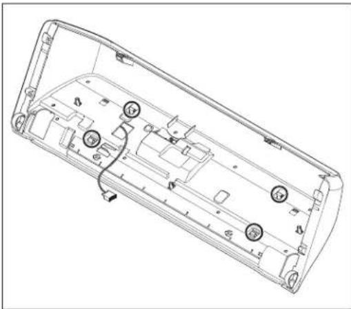
natural_image
Technical line drawing of a device casing with internal components and mounting holes (no text or symbols)- Lift the console shell and remove from UI to access.
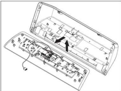
natural_image
Technical line drawing of a device interior showing internal components and wiring (no text or symbols)REASSEMBLY NOTE: When reinstalling the User Interface to the console, only hand tighten the eight (8) hex-head screws until snug. Using a power driver will strip the screw holes and stress the capacitive touch user interface.
FOR SERVICE TECHNICIAN'S USE ONLY
Removing the Water Inlet Valve
WARNING

Electrical Shock Hazard
Disconnect power before servicing.
Replace all parts and panels before operating.
Failure to do so can result in death or electrical shock.
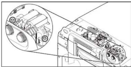
NOTE: The water inlet valve is replaced as an assembly, which includes all four valves, bracket, and valve assembly harness.
- Unplug washer or disconnect power.
- Turn off the water supply to the washer.
- Disconnect hot and cold inlet water hoses.
- Complete the steps 1-8 from section Removing the Console.
- Disconnect the Water Inlet Valve connector from the ACU (connector varies depending on model, features, and control board).
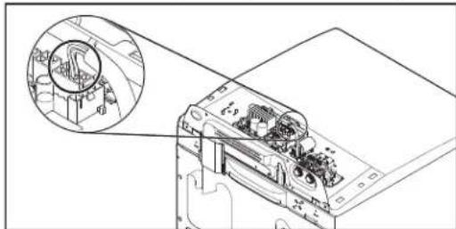
natural_image
Technical line drawing of a mechanical assembly with a magnified inset showing internal components (no text or symbols)- Using a 1/4" nut driver, remove the two (2) hex-head screws (one on each side) securing the water inlet valve to the Top Panel of the washer.
natural_image
Technical line drawing of a mechanical assembly with internal components and a magnified inset (no text or symbols)Removing the Main Control
WARNING

Electrical Shock Hazard
Disconnect power before servicing.
Replace all parts and panels before operating.
Failure to do so can result in death or electrical shock.
NOTE: ACU may vary depending on model number and features.
- Unplug washer or disconnect power.
- Turn off the water supply to the washer.
- Complete the steps 1-8 from section Removing the Console.
- Remove pressure hose from ACU.
- Disconnect all connectors from the ACU.
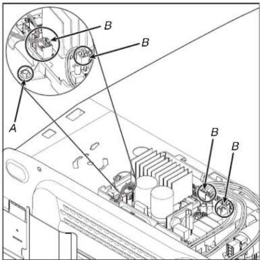
A. ACU Screw B. ACU Connectors
- Using a 1/4" nut driver, remove the hex-head screw securing the ACU to the Top Panel of the washer as shown in above figure. Slide ACU to the left and lift to remove.
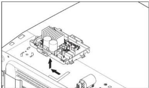
natural_image
Technical line drawing of an electronic circuit board with internal components and directional arrows (no text or symbols)FOR SERVICE TECHNICIAN'S USE ONLY
Removing the Bulk Dispenser
WARNING
Electrical Shock Hazard
Disconnect power before servicing.
Replace all parts and panels before operating.
Failure to do so can result in death or electrical shock.
- Unplug washer or disconnect power.
- Turn off the water supply to the washer.
- Complete the steps 1-8 from section Removing the Console.
- Using a 1/4" nut driver remove the ACU screw and slide ACU to the left.
- Remove 1/4" (6 mm) screw as shown in below figure.
- Push in on harness retainer and lift to disconnect bulk dispense reed switch harness.
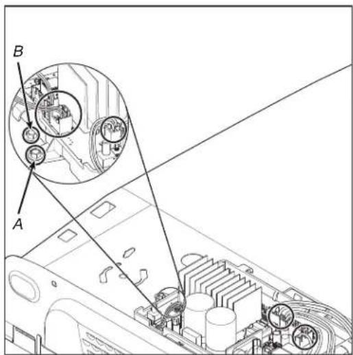
A. ACU Screw B. Dispenser Housing Screw
- Remove 1/4" (6 mm) screw as shown in below figure.
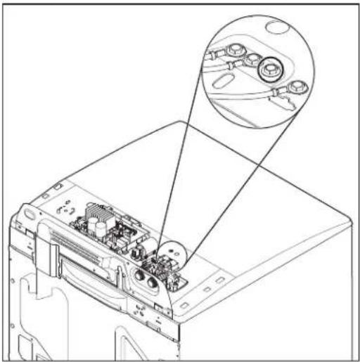
natural_image
Technical line drawing of a computer monitor internal structure with an inset showing internal components (no text or symbols)- Remove inlet valve assembly by removing two (2) 1/4" (6 mm) screws and disconnecting valve harness from ACU. Lift the valve assembly and remove from dispenser housing.
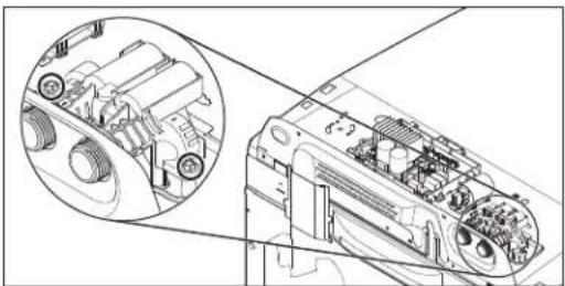
natural_image
Technical line drawing of a mechanical assembly with internal components and a magnified inset (no text or symbols)- Complete the steps 1-8 from section Lifting the Top Panel.
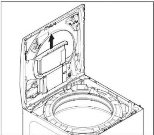
- Lift the bulk drawer and remove it from housing.
natural_image
Technical line drawing of a mechanical assembly with no visible text or symbolsFOR SERVICE TECHNICIAN'S USE ONLY
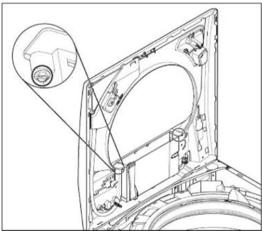
- Remove two (2) 1/4" (6 mm) screws holding dispenser housing to bezel.
natural_image
Technical line drawing of a mechanical assembly with no visible text or symbols-
Using pliers, disconnect fabric softener hose clamp as shown in below figure.
-
Using pliers, disconnect two (2) hose clamps at bulk dispenser pump as shown in below figure.
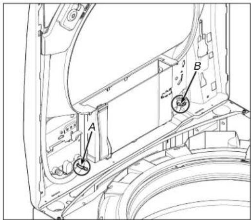
A. Fabric Softener Hose Clamp
B. Clamps at Bulk Dispenser Pump (2)
-
Bulk dispenser housing can now be removed and replaced.
-
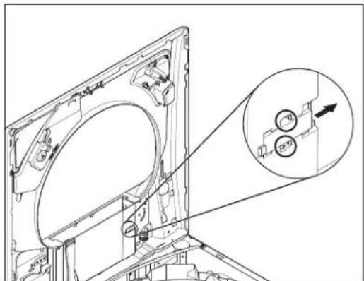
To remove reed switch only use a small screwdriver to push in on tabs and slide to the right.
natural_image
Technical line drawing of a mechanical assembly with an inset showing circular components (no text or symbols)Removing the Tub Ring, Impeller, and Basket
WARNING

Electrical Shock Hazard
Disconnect power before servicing.
Replace all parts and panels before operating.
Failure to do so can result in death or electrical shock.
Lifting the Top Panel
NOTE: There is a new catch at the front left and right of the top panel that needs to be disengaged to remove top panel.
-
Unplug washer or disconnect power.
-
Turn off water supply to washer.
-
Disconnect hot and cold inlet water hoses.
-
Tape lid down.
-
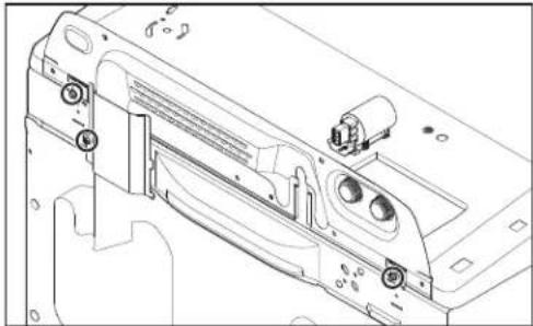
Remove three (3) 1/4" (6 mm) hex-head mounting screws from the rear of the console as indicated. Remove harness cover and set aside.
natural_image
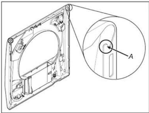
Technical line drawing of a mechanical assembly with mounting holes and internal components (no text or symbols)- To remove the top panel, a tool such as a stiff putty knife must be used to bend up the hook so the tab (Figure B) will be freed from the slot. This allows the top to be slid forward and removed. It is important to insert the putty knife behind the hook (Figure A), not in front of it. Please use care when using these tools to avoid damaging the finish on the consumers unit.
NOTE: Wrap a tape around a putty knife or add a tape to chassis to avoid the damage when pushing the knife down.
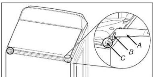
Figure A
A. Putty Knife
B. Hook
C. Slot
FOR SERVICE TECHNICIAN'S USE ONLY
natural_image
Technical line drawing of a mechanical component with an inset view showing a circular feature labeled 'A' (no text or symbols present)Figure B
A. Tab on Underside of Top Panel
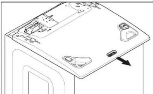
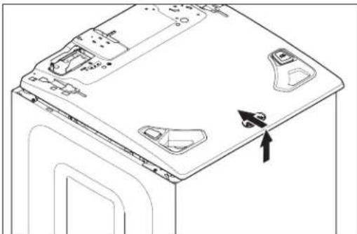
- Slide the Top Panel forward about 1/2" (13 mm).
natural_image
Technical line drawing of a device casing with mounting holes and a directional arrow indicating movement (no text or symbols)- Raise the Top Panel about 1/4" (6 mm). While keeping it lifted, push the Top Panel back about 1/4" (6 mm).
natural_image
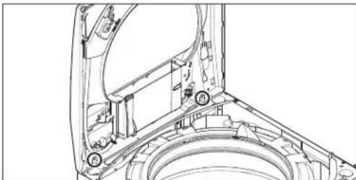
Line drawing of a washing machine front panel with mounting holes and a directional arrow indicating motion (no text or symbols)- Tilt the Top Panel up and make sure that the rear tabs slide into the slots as shown in below figure.
natural_image
Technical line drawing of a mechanical assembly with no visible text or symbolsRemoving the Tub Ring
NOTE: Due to the increase in size and depth of the tub ring, the working space between the tub ring and side panel is very limited.
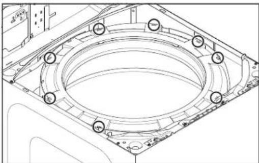
- Locate the eight (8) tub ring clips as shown in below figure. Unclip each clip with a "stubby" flat blade screwdriver.
natural_image
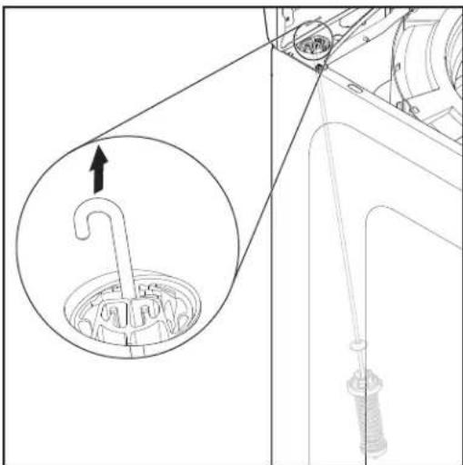
Technical line drawing of a mechanical component with circular features and mounting holes (no text or symbols)- Lift the left-rear suspension rod and disconnect it from the rear brace. This will allow more room to access the two (2) clips located on both sides of the bleach well. Remove tub ring from washer.
natural_image
Technical diagram showing a mechanical assembly with an inset close-up of a curved component (no text or symbols)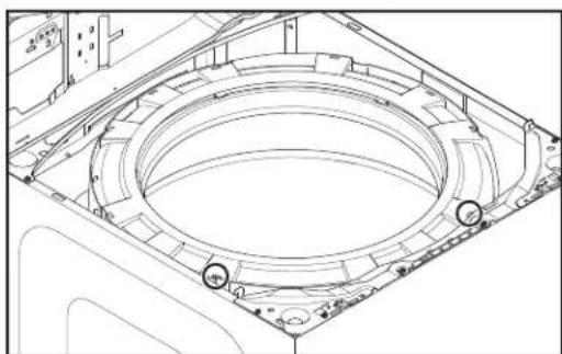
natural_image
Technical line drawing of a mechanical component with concentric circular features and mounting holes (no text or symbols)FOR SERVICE TECHNICIAN'S USE ONLY
Removing the Impeller
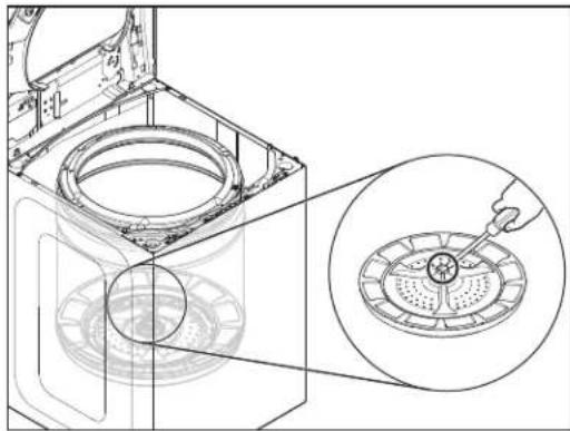
- Insert the blade from a small screwdriver into the slot in the impeller cap, pry the cap up and remove.
natural_image
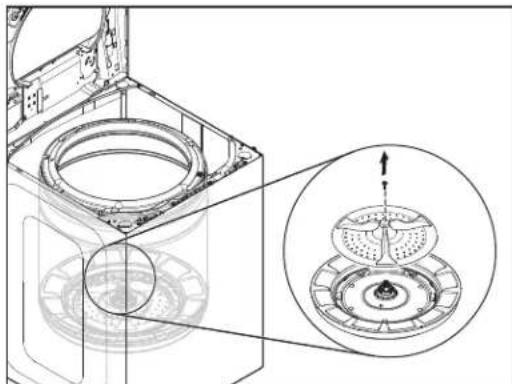
Technical line drawing of a washing machine interior with an inset showing a circular component being inserted (no text or symbols present)- Remove the 7/16" (11 mm) hex-head bolt from the impeller, then lift and remove the impeller from the basket.
natural_image
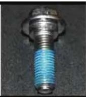
Technical line drawing of a washing machine casing with internal components and a magnified inset showing internal structure (no text or symbols)REASSEMBLY NOTE: Any time the impeller bolt is removed, Loctite ^® adhesive (Threadlocker Blue 242 ^® or similar adhesive) must be reapplied, otherwise the bolt will eventually work itself resulting in a second call.
Removing the Basket
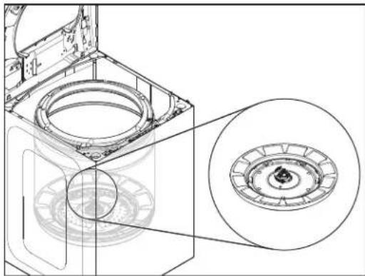
- Using a spanner/wrench and hammer, tap wrench with hammer until nut becomes loose. Remove spanner nut.
natural_image
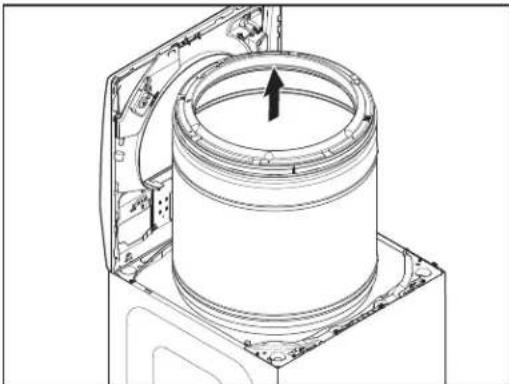
Technical line drawing of a washing machine casing with internal components and a close-up inset showing the circular component (no text or symbols)- Lift the basket out of the washer.
natural_image
Technical line drawing of a mechanical component with a cylindrical housing and mounting bracket (no text or symbols)REASSEMBLY NOTE: When re-installing the basket, screw on spanner nut until it is finger tight. Then, using a mallet or hammer, tighten an additional 3/4 turn (see below figure). Do NOT apply Loctite ^® to spanner nut. Applying Loctite ^® to the spanner nut will make it virtually impossible to remove again.
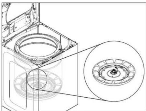
natural_image
Technical line drawing of a washing machine casing with internal components and a close-up inset showing the circular component (no text or symbols)Removing the Lid Lock
WARNING
Electrical Shock Hazard
Disconnect power before servicing.
Replace all parts and panels before operating.
Failure to do so can result in death or electrical shock.
- Unplug washer or disconnect power.
- Turn off water supply to washer.
- Disconnect hot and cold inlet water hoses.
- Complete the steps 1-8 from section Removing the Console.
- Disconnect the Lid Lock connector from the Main Control.(Connector number varies depending on model features).
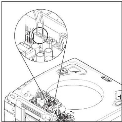
natural_image
Technical line drawing of a mechanical assembly with an inset close-up showing internal components (no text or symbols)- Feed the Lid Lock harness through the opening in the washer Top Panel.
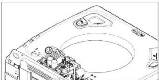
natural_image
Technical line drawing of a mechanical component with internal parts and mounting holes (no text or symbols)- Disconnect push-mount clip from Top Panel.
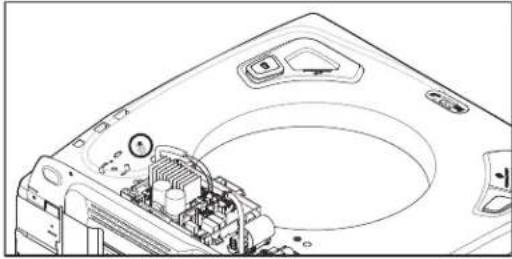
natural_image
Technical line drawing of a computer hard drive with visible circuit board and mounting points (no text or symbols)-
Complete the steps 1-8 from section Lifting the Top Panel.
-
Remove the Lid Lock harness from the clips on right side of Top Panel as shown in below figure.
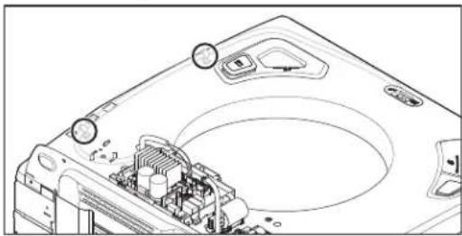
natural_image
Technical line drawing of a computer motherboard with visible circuitry and mounting points (no text or symbols)- Remove the lid lock bezel by pressing the retaining tabs away from the lock.
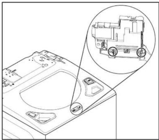
natural_image
Technical line drawing of a washing machine with a magnified inset showing internal components (no text or symbols)- Remove the Lid Lock from the Top Panel by pressing down on the tab as shown in below figure.
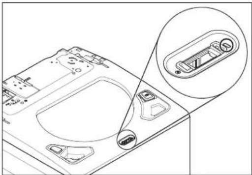
natural_image
Technical line drawing of a mechanical component with an inset close-up view showing internal components (no text or symbols)FOR SERVICE TECHNICIAN'S USE ONLY
- Slide the lid lock to the left and then down to remove.
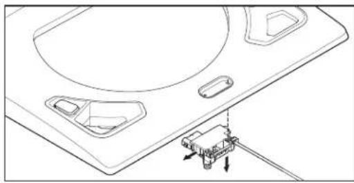
natural_image
Technical line drawing of a device with mounting brackets and a connector (no text or symbols)Removing the Lid and Hinge
WARNING
Electrical Shock Hazard
Disconnect power before servicing.
Replace all parts and panels before operating.
Failure to do so can result in death or electrical shock.
Top Load Washer Glass Lid Removal
- Remove the four (4) TORX T20 screws holding the lid to the hinges.
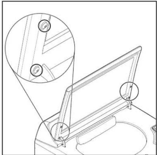
natural_image
Line drawing of a mirror table with an inset close-up showing the mirror structure (no text or symbols)- Lift the lid up and off of the hinges.
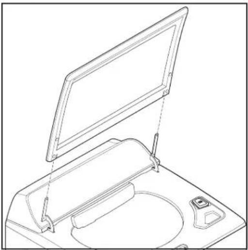
natural_image
Line drawing of a mechanical device with an open lid and base plate (no text or symbols)Top Load Washer Hinge Removal
WARNING
Electrical Shock Hazard
Disconnect power before servicing.
Replace all parts and panels before operating.
Failure to do so can result in death or electrical shock.
- Complete the steps 1-8 from section Removing the Console.
- Complete the steps 1-2 from section Remove the Lid.
- Remove the 1/4" (6 mm) hex head screw holding the hinge in place.
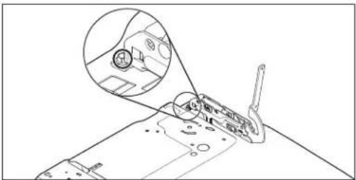
natural_image
Technical line drawing of a mechanical component with an inset close-up showing internal components (no text or symbols)FOR SERVICE TECHNICIAN'S USE ONLY
- Slide the hinge back and lift it to remove.
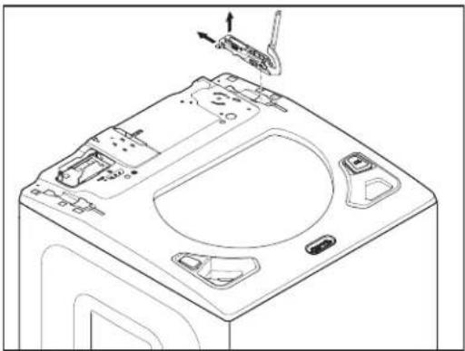
natural_image
Line drawing of a washing machine front panel with handle and control buttons (no text or symbols)Removing the Shifter
WARNING
Electrical Shock Hazard
Disconnect power before servicing.
Replace all parts and panels before operating.
Failure to do so can result in death or electrical shock.
WARNING
Excessive Weight Hazard
Use two or more people to move and install washer.
Failure to do so can result in back or other injury.
- Unplug washer or disconnect power.
- Turn off the water supply to the washer.
- Use cardboard or padding to lay washer on the front cabinet.
- Remove the two (2) mounting screws and then remove the pulley cover.
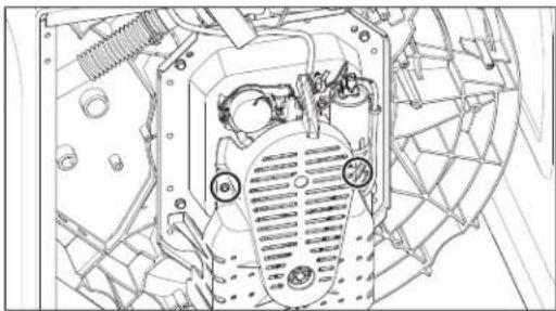
natural_image
Technical line drawing of a mechanical component with no visible text or symbols- Remove the harness from the shifter.
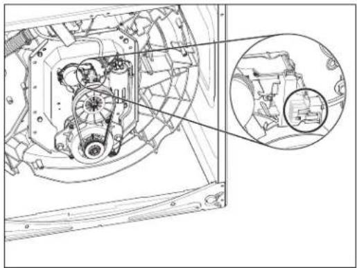
natural_image
Technical line drawing of a mechanical assembly with internal components and a magnified inset showing detail (no text or symbols)- Remove the two (2) mounting screws as shown in below figure.
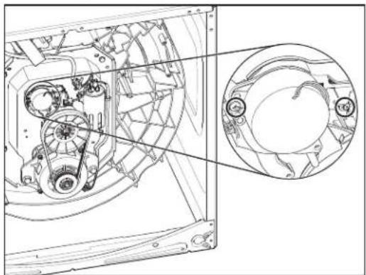
natural_image
Technical line drawing of a mechanical assembly with internal components and a circular inset view (no text or symbols)- Lift out the shifter.
FOR SERVICE TECHNICIAN'S USE ONLY
Removing the Drain Pump
WARNING
Electrical Shock Hazard
Disconnect power before servicing.
Replace all parts and panels before operating.
Failure to do so can result in death or electrical shock.
WARNING
Excessive Weight Hazard
Use two or more people to move and install washer.
Failure to do so can result in back or other injury.
- Unplug washer or disconnect power.
- Turn off the water supply to the washer.
- Use cardboard or padding to lay washer on the front cabinet.
- Disconnect hoses to drain pump.
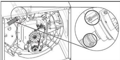
natural_image
Technical line drawing of a mechanical assembly with internal components and a magnified inset showing internal parts (no text or symbols)- Remove the harness from the pump motor.
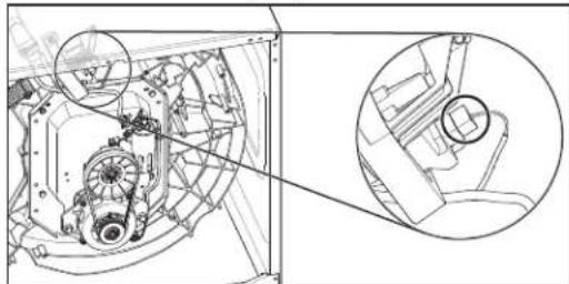
natural_image
Technical line drawing of a mechanical assembly with two views: top shows internal components, bottom shows close-up of a circular component (no text or symbols)- Remove three (3) mounting screws.
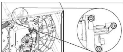
natural_image
Technical line drawing of a mechanical assembly with an inset close-up view (no text or symbols)- Remove pump assembly by lifting up and away from the tub.
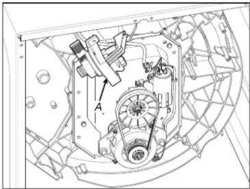
A. Drain Pump
Removing the Drive Belt and Motor
WARNING
Electrical Shock Hazard
Disconnect power before servicing.
Replace all parts and panels before operating.
Failure to do so can result in death or electrical shock.
WARNING
Excessive Weight Hazard
Use two or more people to move and install washer.
Failure to do so can result in back or other injury.
- Unplug washer or disconnect power.
- Turn off the water supply to the washer.
- Use cardboard or padding to lay washer on the front cabinet.
- Remove the two (2) mounting screws followed by pulley cover.
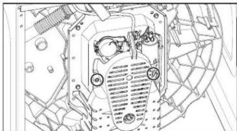
natural_image
Technical line drawing of a mechanical component with no visible text or symbolsFOR SERVICE TECHNICIAN'S USE ONLY
- To remove the belt, pull out on the belt and turn the splutch pulley until the belt slides off.
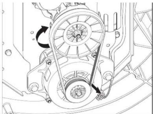
natural_image
Technical line drawing of a mechanical assembly with pulleys and gears (no text or symbols)- Unplug the harness and remove the two (2) mounting bolts. Now you can remove the motor.
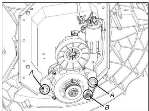
A. Motor Screws B. Motor Harness (Lower)
Removing the Splutch
WARNING

Electrical Shock Hazard
Disconnect power before servicing.
Replace all parts and panels before operating.
Failure to do so can result in death or electrical shock.
WARNING
Excessive Weight Hazard
Use two or more people to move and install washer.
Failure to do so can result in back or other injury.
- Unplug washer or disconnect power.
- Turn off the water supply to the washer.
- Complete the steps 1-6 from section Removing the Drive Belt and Motor.
- Hold the splutch pulley and remove the mounting nut.
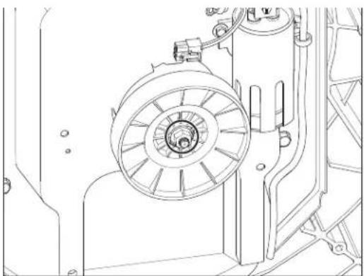
natural_image
Technical line drawing of a mechanical assembly with no visible text or symbols- Lift off the pulley.
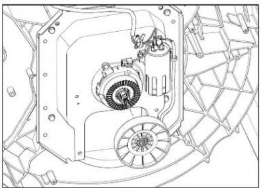
natural_image
Technical line drawing of a mechanical assembly with gears and housing (no text or symbols)FOR SERVICE TECHNICIAN'S USE ONLY
- Complete the steps 1-7 from section Removing the Shifter to remove the shifter.
- Unsnap the tabs that secure the splutch housing and lift off.
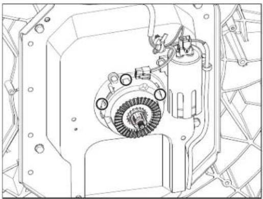
natural_image
Technical line drawing of a mechanical assembly with gears and housing (no text or symbols)Removing the Gearcase
WARNING

Electrical Shock Hazard
Disconnect power before servicing.
Replace all parts and panels before operating.
Failure to do so can result in death or electrical shock.
WARNING
Excessive Weight Hazard
Use two or more people to move and install washer.
Failure to do so can result in back or other injury.
- Unplug washer or disconnect power.
- Turn off the water supply to the washer.
- Complete the steps 1-2 from section Removing the Impeller.
- Complete the steps 1-2 from section Removing the Basket.
- Use cardboard or padding to lay washer on the front cabinet.
- Complete the steps 1-6 from section Removing the Drive Belt and Motor.
- Complete the steps from 1-7 Removing the Splutch.
-
Complete the steps 1-7 from section Removing the Shifter.
-
Remove the capacitor by disconnecting harness and removing mounting screws as shown in below figures.
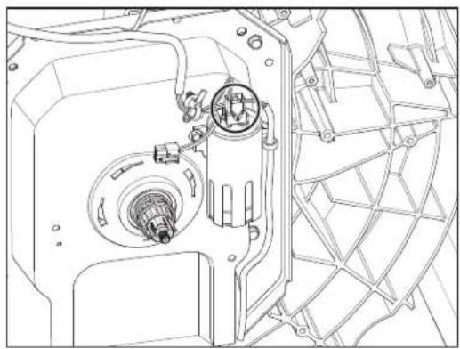
natural_image
Technical line drawing of a mechanical assembly with internal components (no text or symbols)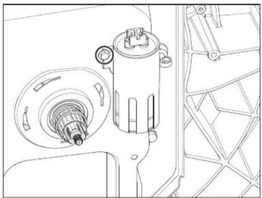
natural_image
Technical line drawing of a mechanical assembly with gears and housing (no text or symbols)-
Complete the steps 1-7 from section Removing the Drain Pump.
-
Remove the four (4) mounting bolts.
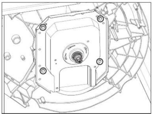
natural_image
Technical line drawing of a mechanical assembly with mounting holes and internal components (no text or symbols)- Pull the gearcase out of the tub.
FOR SERVICE TECHNICIAN'S USE ONLY
As an alternative to the previous steps, the belt, motor, splutch, shifter, and capacitor may also be removed along with the gearcase as outlined below:
- Unplug washer or disconnect power.
- Turn off the water supply to the washer.
- Remove the basket. See the section Removing the Basket.
- Use cardboard or padding to lay washer on the front cabinet.
- Unplug the harness from the motor.
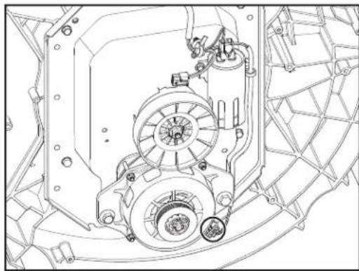
natural_image
Technical line drawing of a mechanical assembly with no visible text or symbols- Unplug the harness from Shifter.
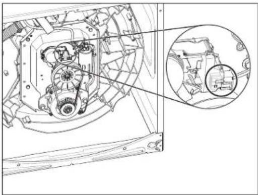
natural_image
Technical line drawing of a mechanical assembly with internal components and a magnified inset (no text or symbols)- Unplug the harness from the capacitor.
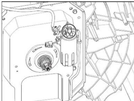
natural_image
Technical line drawing of a mechanical assembly with internal components (no text or symbols)- Remove the four (4) mounting bolts and pull the gearcase out of the tub
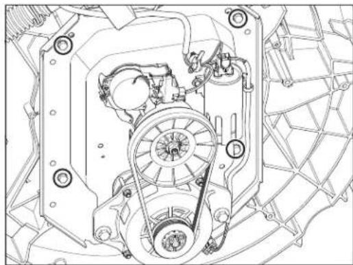
natural_image
Technical line drawing of a mechanical assembly with gears and housing (no text or symbols)NOTE: The tub and gearcase has eight (8) mounting holes. Only four (4) are used. If they strip out during reassembly, the other holes can be used to re-mount the gearcase.
FOR SERVICE TECHNICIAN'S USE ONLY
! DANGER

SPÉCIFICATIONS DU PRODUIT
SPÉCIFICATIONS DU PRODUIT
natural_image
Diagram of a cable connection setup with wires and connectors, no text or symbols presentnatural_image
Technical line drawing of a mechanical assembly with mounting brackets and internal components (no text or symbols)natural_image
Technical line drawing of an internal electronic device casing with visible circuitry and components (no text or labels)natural_image
Technical line drawing of an open electronic device casing with internal components and a black arrow indicating rotation (no text or symbols)natural_image
Technical line drawing of an open refrigerator with internal components and a magnified inset showing internal structure (no text or symbols)natural_image
Technical line drawing of a remote control panel with visible buttons and casing (no text or labels)natural_image
Technical line drawing of a device casing with internal components and mounting holes (no text or symbols)natural_image
Technical line drawing of a device casing with internal components and wiring (no text or symbols)natural_image
Technical line drawing of a mechanical assembly with an inset showing internal components (no text or symbols)natural_image
Technical line drawing of a mechanical assembly with internal components and a magnified inset (no text or symbols)natural_image
Isometric technical diagram of an electronic circuit board with internal components and directional arrows (no text or labels)natural_image
Technical line drawing of a computer monitor internal structure with an inset showing internal components (no text or symbols)natural_image
Technical line drawing of a mechanical assembly with internal components and a magnified inset (no text or symbols)natural_image
Technical line drawing of a mechanical assembly with no visible text or symbolsnatural_image
Technical line drawing of a mechanical assembly with no visible text or symbolsnatural_image
Technical line drawing of a mechanical assembly with an inset showing circular components (no text or symbols)natural_image
Technical line drawing of a mechanical assembly with mounting holes and internal components (no text or symbols)Figure A
natural_image
Technical line drawing of a mechanical component with an inset view showing a circular feature labeled 'A' (no text or symbols present)natural_image
Technical line drawing of a device casing with internal components and an arrow indicating direction (no text or symbols)natural_image
Technical line drawing of a front-mounted appliance with mounting holes and a directional arrow indicating motion (no text or symbols)natural_image
Technical line drawing of a mechanical assembly with no visible text or symbolsnatural_image
Technical line drawing of a mechanical component with circular features and mounting holes (no text or symbols)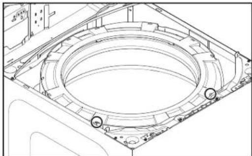
natural_image
Technical line drawing of a mechanical component with concentric circular features and mounting brackets (no text or symbols)natural_image
Technical line drawing of a washing machine interior with an inset showing a circular component being inserted (no text or symbols present)natural_image
Technical line drawing of a washing machine interior with a magnified inset showing internal components (no text or symbols)natural_image
Technical line drawing of a washing machine casing with internal components and a close-up inset showing the circular component (no text or symbols)natural_image
Technical line drawing of a mechanical assembly with a cylindrical component and mounting bracket (no text or symbols)natural_image
Technical line drawing of a washing machine casing with circular components and a magnified inset showing internal structure (no text or symbols)natural_image
Technical line drawing of a mechanical assembly with an inset close-up showing internal components (no text or symbols)natural_image
Technical line drawing of a mechanical device with no visible text or symbolsnatural_image
Technical line drawing of a computer motherboard showing internal components and casing (no text or symbols)natural_image
Technical line drawing of a computer motherboard showing internal components and mounting points (no text or labels)natural_image
Technical line drawing of a washing machine casing with a magnified inset showing internal components (no text or symbols)natural_image
Technical line drawing of a mechanical component with an inset close-up showing a button mechanism (no text or symbols)natural_image
Technical line drawing of a device with mounting holes and a small component inserted (no text or symbols)natural_image
Line drawing of a desk lamp with two circular insets showing structural details (no text or symbols)natural_image
Line drawing of a mechanical device with an open lid and internal components (no text or symbols)natural_image
Line drawing of a mechanical component with an inset close-up showing internal components (no text or symbols)natural_image
Line drawing of a washing machine front panel with handle and control buttons (no text or symbols)natural_image
Technical line drawing of a mechanical component with no visible text or symbolsnatural_image
Technical line drawing of a mechanical assembly with internal components and a magnified inset (no text or symbols)natural_image
Technical line drawing of a mechanical assembly with internal components and a close-up inset (no text or symbols)natural_image
Technical line drawing of a mechanical assembly with no visible text or symbolsnatural_image
Technical line drawing of a mechanical assembly with circular annotations highlighting features (no readable text or symbols)natural_image
Technical line drawing of a mechanical assembly with an inset close-up view (no text or symbols)A. Pompe de vidange
natural_image
Technical line drawing of a mechanical component with no visible text or symbolsnatural_image
Technical line drawing of a mechanical assembly with pulleys and gears (no text or symbols)natural_image
Technical line drawing of a mechanical assembly with no visible text or symbols- Retirer la poulie.
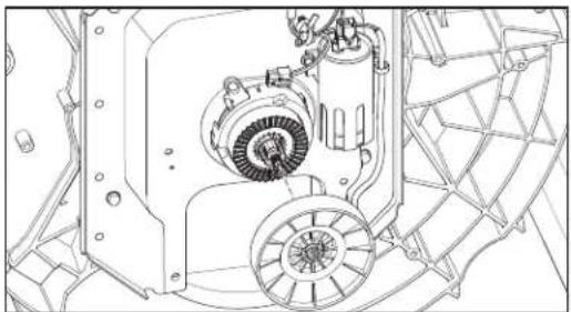
natural_image
Technical line drawing of a mechanical assembly with gears and housing (no text or symbols)natural_image
Technical line drawing of an electric motor assembly with cooling fan and mounting bracket (no text or labels)natural_image
Technical line drawing of a mechanical assembly with internal components (no text or symbols)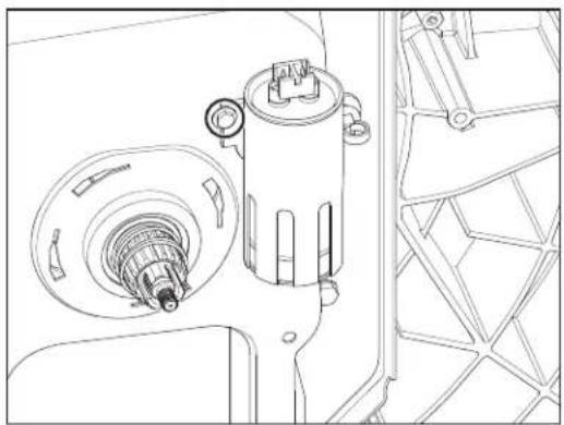
natural_image
Technical line drawing of a mechanical assembly with no visible text or symbolsnatural_image
Technical line drawing of a mechanical assembly with mounting holes and internal components (no text or symbols)natural_image
Technical line drawing of a mechanical assembly with no visible text or symbolsnatural_image
Technical line drawing of a mechanical assembly with internal components and a magnified inset (no text or symbols)natural_image
Technical line drawing of a mechanical assembly with internal components (no text or symbols)natural_image
Technical line drawing of a mechanical assembly with gears and housing (no text or symbols)natural_image
Diagram of a cable connection setup with wires and connectors, no text or symbols presentFigura 4: Control principal (ACU)
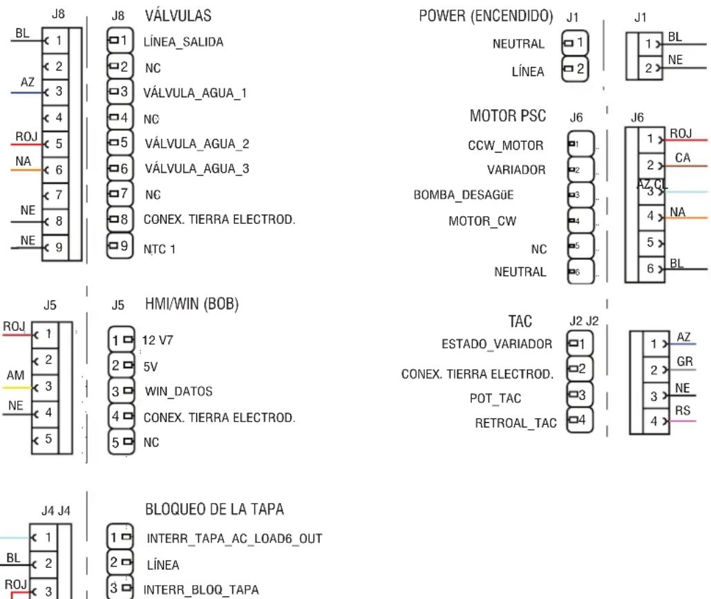
Figura 5: Conector y patillas
Figura 7: Control principal (ACU)
Conector del motor PSC
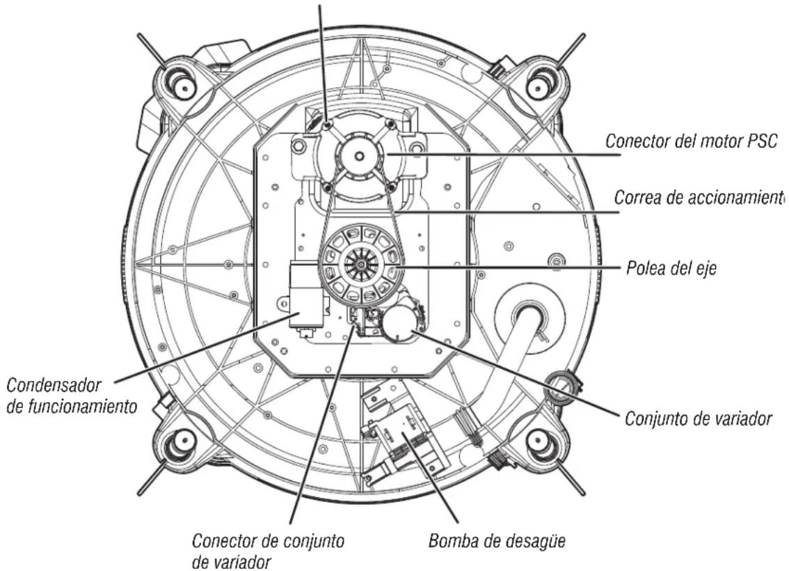
natural_image
Technical line drawing of a mechanical device with mounting brackets and internal components (no text or symbols)natural_image
Technical line drawing of an internal electronic device casing with visible circuitry and ports (no text or symbols)natural_image
Technical line drawing of an open electronic device casing with internal components and a curved arrow indicating rotation (no text or symbols)natural_image
Technical line drawing of an open refrigerator with internal components and a magnified inset showing internal structure (no text or symbols)natural_image
Technical line drawing of a remote control panel with visible buttons and casing (no text or symbols)natural_image
Technical line drawing of a device casing with internal components and mounting holes (no text or symbols)natural_image
Technical line drawing of a device interior showing internal components and wiring (no text or symbols)natural_image
Technical line drawing of a mechanical assembly with a magnified inset showing internal components (no text or symbols)natural_image
Technical line drawing of a mechanical assembly with internal components and a magnified inset (no text or symbols)natural_image
Technical line drawing of an electronic circuit board with internal components and directional arrows (no text or symbols)natural_image
Technical line drawing of a computer chassis with an inset showing internal components (no text or symbols)natural_image
Technical line drawing of a mechanical assembly with internal components and a magnified inset (no text or symbols)natural_image
Technical line drawing of a mechanical housing or enclosure with internal components and an arrow indicating direction (no text or symbols present)natural_image
Technical line drawing of a mechanical assembly with no visible text or symbolsnatural_image
Technical line drawing of a mechanical assembly with an inset showing a close-up of a component (no text or symbols present)natural_image
Technical line drawing of a mechanical component with mounting holes and internal structure (no text or symbols)natural_image
Technical line drawing of a mechanical component with an inset showing a close-up view of a component labeled A, B, and C (no text or symbols present)Figura A
A. Cuchillo para masilla
B. Gancho
C. Ranura
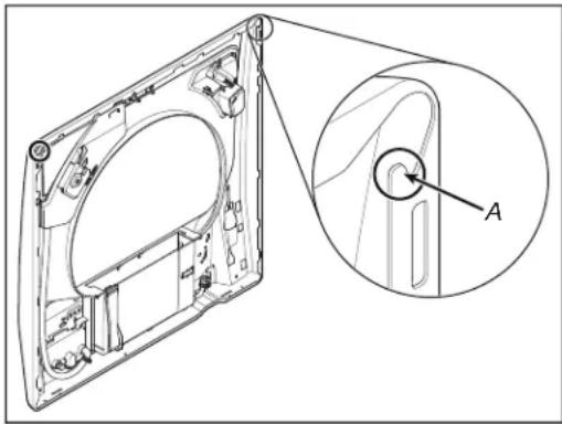
natural_image
Technical line drawing of a mechanical component with an inset view labeled 'A' (no text or symbols present)natural_image
Technical line drawing of a door frame with mounting holes and a car component, no text or symbols presentnatural_image
Technical line drawing of a front-mounted appliance with mounting holes and a directional arrow indicating motion (no text or symbols)natural_image
Technical line drawing of a mechanical assembly with no visible text or symbolsnatural_image
Technical line drawing of a circular mechanical component with mounting holes and internal channels (no text or symbols)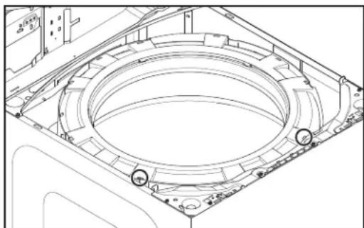
natural_image
Technical line drawing of a mechanical component with concentric circular features and mounting holes (no text or symbols)natural_image
Technical line drawing of a washing machine interior with an inset showing a circular component being inserted (no text or symbols present)natural_image
Technical line drawing of a washing machine interior with a magnified inset showing internal components (no text or symbols)natural_image
Technical line drawing of a washing machine casing with internal components and a close-up inset showing the circular component (no text or symbols)natural_image
Technical line drawing of a mechanical component with a cylindrical housing and an arrow indicating direction (no text or symbols)natural_image
Technical line drawing of a washing machine casing with internal components and a close-up inset showing the circular component (no text or symbols)natural_image
Technical line drawing of a mechanical assembly with internal components and a magnified inset showing a component detail (no text or symbols)natural_image
Technical line drawing of a computer motherboard showing CPU socket, buttons, and internal components (no text or labels)natural_image
Technical line drawing of a computer motherboard showing internal components like CPU socket and drive bays (no text or labels)natural_image
Technical line drawing of a computer motherboard showing key components like CPU socket and drive bays (no text or labels)natural_image
Technical line drawing of a washing machine with a close-up inset showing internal components (no text or symbols)natural_image
Technical line drawing of a washing machine component with an inset close-up showing the internal mechanism (no text or symbols)natural_image
Technical line drawing of a device with mounting holes and a small component inserted (no text or symbols)natural_image
Technical line drawing of a desk lamp with two circular components inserted, showing structural details (no text or symbols)natural_image
Line drawing of a mechanical device with a lid and base plate (no text or symbols)natural_image
Line drawing of a mechanical component with an inset close-up showing internal components (no text or symbols)natural_image
Line drawing of a washing machine front panel with handle and control buttons (no text or symbols)natural_image
Technical line drawing of a mechanical assembly with no visible text or symbolsnatural_image
Technical line drawing of a mechanical assembly with internal components and a magnified inset showing detail (no text or symbols)natural_image
Technical line drawing of a mechanical assembly with internal components and a magnified inset (no text or symbols)natural_image
Technical line drawing of a mechanical assembly with no visible text or symbolsnatural_image
Technical line drawing of a mechanical assembly with an inset close-up view (no text or symbols)natural_image
Technical line drawing of a mechanical assembly with internal components and a magnified inset showing a close-up view (no text or symbols)A. Bomba de desagüe
natural_image
Technical line drawing of a mechanical assembly with no visible text or symbolsnatural_image
Technical line drawing of a mechanical assembly with pulleys and gears (no text or symbols)natural_image
Technical line drawing of a mechanical assembly with no visible text or symbols- Levante la polea.
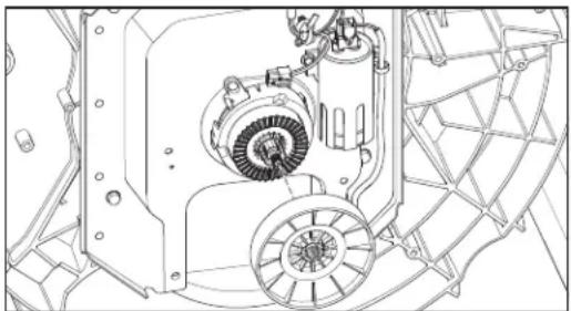
natural_image
Technical line drawing of a mechanical assembly with gears and housing (no text or symbols)natural_image
Technical line drawing of a mechanical assembly with gears and housing (no text or symbols)natural_image
Technical line drawing of a mechanical assembly with internal components (no text or symbols)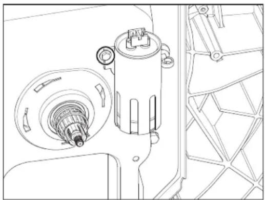
natural_image
Technical line drawing of a mechanical assembly with gears and housing (no text or symbols)natural_image
Technical line drawing of a mechanical assembly with mounting holes and internal components (no text or symbols)natural_image
Technical line drawing of a mechanical assembly with no visible text or symbolsnatural_image
Technical line drawing of a mechanical assembly with internal components and a magnified inset (no text or symbols)natural_image
Technical line drawing of a mechanical assembly with no visible text or symbolsnatural_image
Technical line drawing of a mechanical assembly with gears and housing (no text or symbols)- WARNING
- Voltage Measurement Safety Information
- IMPORTANT: Electrostatic Discharge (ESD) Sensitive Electronics
- IMPORTANT SAFETY NOTICE — “For Technicians only”
- FOR SERVICE TECHNICIAN'S USE ONLY
- Contents
- GENERAL INFORMATION 3-8
- Service Guide 9-18
- Troubleshooting 19-28
- Component Access 29-40
- GENERAL INFORMATION
- WASHER SAFETY
- Your safety and the safety of others are very important.
- DANGER
- IMPORTANT SAFETY INSTRUCTIONS
- SAVE THESE INSTRUCTIONS
- PRODUCT SPECIFICATIONS
- MAYTAG® MODEL NUMBER NOMENCLATURE
- MODEL NUMBER M V W 6200 K W
- MODEL NUMBER AND SERIAL NUMBER LABEL LOCATION
- TECH SHEET LOCATION
- SERVICE GUIDE
- DIAGNOSTIC LED - MAIN CONTROL (ACU)
- SERVICE MODE
- ACTIVATING SERVICE MODE
- Unsuccessful Activation
- Activation with Saved Fault Codes
- READING BINARY CODES
- BUTTON ACTIVATION & ENCODER TEST
- Entry Procedure
- DIAGNOSTIC: Button Activation & Encoder Test
- Button Activation Test
- Exit Procedure
- SERVICE TEST MODE
- Active Fault Code Display in Service Test Mode
- SOFTWARE VERSION DISPLAY
- FAULT/ERROR CODES
- Advancing Through Saved Fault/Error Codes
- Clearing Fault Codes
- EXITING SERVICE DIAGNOSTIC MODE
- DIAGNOSTIC CYCLE CHART
- FAULTS AND ERROR CODES
- TROUBLESHOOTING
- TROUBLESHOOTING GUIDE
- Troubleshooting Pinched Wires in the Harness
- TROUBLESHOOTING TESTS
- TEST #1: Main Control (ACU)
- TEST #2: Valves
- TEST #3: Drive System
- TEST #3a: Drive System – Shifter
- Functional Check:
- basket and impeller turn freely, go to step 4.
- visual checks pass, go to step 6.
- Shifter Motor:
- values are correct, reconnect J6 and proceed to step 7.
- values are open or out of range, go to step 12.
- Shifter Switch:
- Optical Sensor:
- visual check passes, go to step 14.
- there is no continuity, replace the lower washer harness and repeat step 1.
- TEST #3b: Drive System – Motor
- visual check passes, go to step 13.
- connections are loose, reconnect the electrical connections, reassemble motor cover, and repeat step 1.
- TEST #4: HMI
- TEST #5: Temperature Thermistor
- TEST #6: Water Level
- TEST #7: Drain Pump
- TEST #8: Lid Lock
- COMPONENT ACCESS
- Removing the Console
- Removing the User Interface (UI)
- Electrical Shock Hazard
- Removing the Water Inlet Valve
- Removing the Main Control
- Removing the Bulk Dispenser
- Removing the Tub Ring, Impeller, and Basket
- Lifting the Top Panel
- Removing the Tub Ring
- Removing the Impeller
- Removing the Basket
- Removing the Lid Lock
- Top Load Washer Glass Lid Removal
- Excessive Weight Hazard
- Removing the Drain Pump
- Removing the Drive Belt and Motor
- Removing the Splutch
- ! DANGER
- SPÉCIFICATIONS DU PRODUIT
Brand : MAYTAG
Model : MVW6200KW
Category : Washing machine