
XBS-CAN-AC-800 - Gate automation AccessPRO - Free user manual and instructions
Find the device manual for free XBS-CAN-AC-800 AccessPRO in PDF.


| Product Type | Automatic sliding gate opener |
| Brand | AccessPRO |
| Model | XBS-CAN-AC-800 |
| Power Supply | 110 VAC / 60 Hz |
| Motor Power | 280 W |
| Motor Current | 8 A |
| Motor Speed | 1400 r/min |
| Max Gate Weight | 800 kg |
| Thermal Protection Temperature | 120°C |
| Working Temperature Range | -20°C to 55°C |
| Limit Switch Type | Magnetic or mechanical (depending on version) |
| Control Board | Built-in with terminals for push button, photocell, alarm lamp |
| Auto-Closing | Available with adjustable pause time |
| Soft Start/Stop | Adjustable via trimmers |
| Resistance Force Adjustment | Via trimmer VR3 |
| Power Regulation | Adjustable via trimmer VR4 |
| Photocell Input | Yes (N.C.) |
| Alarm Lamp Output | Available |
| Transmitter Learning | Step-by-step and opening modes |
| Safety Devices | Photocells, sensitive edges (user supplied) |
| Maintenance | Regular inspection of cables, springs, mountings; disconnect power before cleaning |
| Replaceable Parts | Fuse, motor, limit switch, release handle |
| Installation Requirement | Must be installed by a professional |
Frequently Asked Questions - XBS-CAN-AC-800 AccessPRO
User questions about XBS-CAN-AC-800 AccessPRO
0 question about this device. Answer the ones you know or ask your own.
Ask a new question about this device
Download the instructions for your Gate automation in PDF format for free! Find your manual XBS-CAN-AC-800 - AccessPRO and take your electronic device back in hand. On this page are published all the documents necessary for the use of your device. XBS-CAN-AC-800 by AccessPRO.
USER MANUAL XBS-CAN-AC-800 AccessPRO
natural_image
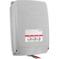
Exterior view of a white industrial electrical enclosure with mounting base (no text or symbols visible)XBS-CAN-AC-800
PLEASE READ THE MANUAL CAREFULLY BEFORE INSTALL AND USE
WARNING TO THE INSTALLER AND USER
1) CAUTION! For personal safety it is important to follow all the instructions carefully. Incorrect installation or misuse of the product may cause serious harm to people.
2) Keep the instructions in a safe place for future reference.
3) This product was designed and manufactured strictly for the use indicated in this document. Any other usage not expressly indicated in this Document, may damage the product and/or be a source of danger.
4) BS accepts no responsibility due to improper use of the automatic machine (opener) or use other than that intended.
5) Do not install the machine in an area subject to explosion hazard. Inflammable gasses or fumes are a serious safety hazard.
6) BS will not accept responsibility if the rules of good workmanship are disregarded in installing the closing elements to be motorised, if any deformation occurs during use of the said elements.
7) Before carrying out any work on the system, turn off the electricity supply.
8) The safety devices(e.g.photocells,sensitive edges, etc...) may be used to prevent any potential risk in dangerous areas where the moving mechanism is located, such as crushing, dragging, or shearing.
9) BS accepts no responsibility regarding safety and correct operation of the machine, should components made by manufacturers other than we be used in the system.
10) Do not make any alterations to the components of the automatic machine (opener and accessory).
11) The installer must supply full information regarding operation manual of the system in the event of any emergency and provide the system user with the "INSTRUCTION" included with the product.
12) Do not allow children or other people to stand near any moving part of the opener or door construction while in operation.
13) Keep transmitters away from children to prevent the machine from being activated accidentally.
14) The user must refrain from attempting to repair or adjust the system personally and should only contact professional personnel.
15) Frequently examine the installation, in particular check cables, springs and mountings for signs of wear, damage or imbalance. Do not use if repair or adjustment is needed since a fault in installation or an incorrectly balanced door may cause injury.
16) This appliance is not intended for use by persons (including children) with reduced physical, sensory or mental capabilities, or lack of experience and knowledge, unless they have been given supervision or instruction concerning use of the appliance by a person responsible for their safety.
17) If the supply cord is damaged, it must be replaced by the manufacturer, its service agent or similarly qualified persons in order to avoid a hazard.
18) Disconnect the supply when cleaning or other maintenance is being carried out, if the appliance is automatically controlled.
19) The temperature range marked on the drive should be suitable for the location.
20) The electrical cord plug must plug in indoor outlet or waterproof cover outlet
1. Instruction
| BS-CAN-I Complete kit |  Release key Release key |  Limit magnet/ Bracket Limit magnet/ Bracket |  | |
 Transmitters Transmitters |  Base plate Base plate | 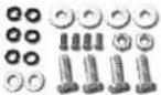 Accessories Accessories | BS-CAN-I | |
| BS-CAN-II Complete kit |  Release key Release key |  Limit stopper Limit stopper |  |
 Transmitters Transmitters |  Base plate Base plate |  Accessories Accessories | BS-CAN-II |
1.1 Dimension
BS-CAN-I

natural_image
3D rendering of a mechanical component with a gear and shaft (no text or symbols visible)Magnetic limit switch
BS-CAN-II

natural_image
3D rendering of a mechanical device with a gear and mounting base (no visible text or symbols)Mechanical limit switch

natural_image
Technical line drawing of a mechanical component with dimension annotations (no text or symbols)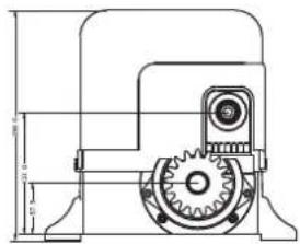
* Built-in control board.
* Terminals for Push button, Photocell, Alarm lamp.
* Auto-closing is available, time delay is adjustable.
1.2 Technical Specifications
| Model | XBS-CAN-AC |
| Description | AC MOTOR |
| Power supply | 110 VAC / 60 Hz |
| Power of Motor | 280W |
| Current | 8 A |
| Motor rotational speed | 1400r/min |
| Max weight of gate | ≤800kg |
| Thermal protection on motor winding | 120°C |
| Working environment | -20°C~55°C |
2. Installation
* Before using the machine, check power supply, grounding, voltage, etc.
* Check whether it is connected according to the demand of wiring diagram.
* The gate should be pulled easily and smoothly manually when the worm gears are released.
* The worm gears will be coupled before power on.
* The product must be installed by professional person.
2.1 Example of an installed automatic sliding gate
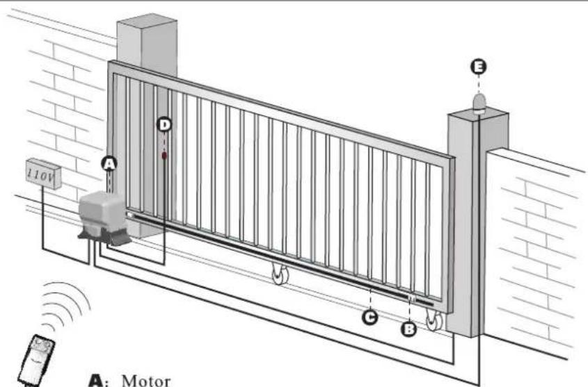
A: Motor
B: Limit stopper or Limit magnet
C: Rack
D: Photocell
E: Alarm lamp
Fig 2
2.2 Installation and adjustment
2.2.1 Install baseplate on the ground, then, fasten the sliding motor on the base-plate.
Key: Ensure baseplate on level position.

Fig 3
2.2.2 Install the limit stopper or limit magnet at proper position on the steel rack.


Before place the limit stoper or magnet on the rack, the gear box of the operator must be released. As per Fig 6A or fig 6B, Use the key turn clockwise to release the gear.

Move the gate manually to the open limit and close limit, mark the points on the Rack, then, fix the limit Stoppers or Magnets at the limit points on the Rack.
2.2.3 XBS-CAN-AC-800 standard installation layout
When the Operator is installed on Left Side.
Close Limit stopper or Magnet

Closed state
Open Limit stopper or Magnet

Open state

CONTROL BOARD
When the Operator is installed on Right Side.
Close Limit stopper or Magnet
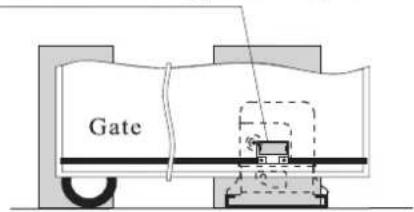
Closed state
Open Limit stopper or Magnet
Open state

CONTROL BOARD
Fig8
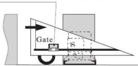
NOTE: Magnet must be 10mm\~20mm space from the operator, and must be same height with the Magnetic switch inside of the Operator.
- Layout of PCB and wiring diagram

Fig10
- VR3: Trimmer of resistance force
10.Photocell LED(N.C.) - VR2: Trimmer of pausing time
- Close limit LED(N.C.)
- VR1: Trimmer of slowing power
12.Open limit LED(N.C.) - VR4: Trimmer of power regulation
- Receiver
5.Push button
14.Fuse(0.2A) - Test button
15.Fuse(5A/220V, 8A/110V) - Learn button
- Transformer
- Status LED(Flash on running)
- Jumper for reverse function(ON:valid, OFF:invalid)

flowchart
graph TD
    A["Ant"] --> B["LIMIT"]
    B --> C["IR GND"]
    C --> D["OPN STP GND CLS PS"]
    D --> E["AC24V"]
    B --> F["Photo"]
    C --> G["STOP button"]
    C --> H["Close button"]
    C --> I["Push button"]
    F --> J["Receiver"]
    G --> J
    H --> J
    I --> J
    J --> K["Emitter"]
    style A fill:#f9f,stroke:#333
    style K fill:#ccf,stroke:#333
    style B fill:#cfc,stroke:#333
    style C fill:#fcc,stroke:#333
    style D fill:#cff,stroke:#333
    style E fill:#ffc,stroke:#333
    style F fill:#fcc,stroke:#333
    style G fill:#fcc,stroke:#333
    style H fill:#fcc,stroke:#333
    style I fill:#fcc,stroke:#333
    style J fill:#cff,stroke:#333
    style K fill:#ffc,stroke:#333
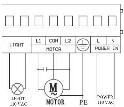
Fig 11
Dip-switch set up
 | Enable auto close |  | Disable auto close |
 | Enable soft start |  | Disable soft start |
 | Enable soft stop |  | Disable soft stop |
| [GD8] | Step by step mode |  | No use |

VR1

VR1: Trimmer of power adjustment during soft stop.
VR2: Trimmer of pausing time for Auto-closing at Open Limit.
VR3: Trimmer of resistance force.
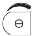
VR4: Trimmer of motor power adjustment.

VR4
Running time programming
After finish the installing and connecting, Power on, and Press "Test" for 3 second, the gate will open and close at the limit point one cycle, the running time is remembered by the control system.
If no limit stopper or limit magnet on the rack, you also can press "Test" when the gate open and close to the right limit points.
Transmitter's code setting
- Learning a button on transmitter for step by step operation:
Sortly press “LEARN” button on control board, “LEARN” LED light on, then press and hold the required button on transmitter till the “Learn” LED flashes and goes out.
- Learning a button on transmitter for opening operation:
Sortly press "LEARN" button twice on control board, "LEARN" LED flashes twice, then press another button on transmitter till the "LEARN" LED flashes and goes out.
This way, more transmitters can be learned.
Erasing the transmitter's code
Erasing transmitter codes: Press" LEARN " button and hold on to make the "LEARN" LED light till go out. Now, all codes of transmitters which had been learnt are cleared.
Trouble Shooting
| Number | Trouble | Cause | Shooting |
| 1 | motor can not work | *No power supply*Break fuse*Motor is damaged | *Check power supply*Change fuse*Change the motor |
| 2 | Can open but can not close | *Photocell is not connected properly*Photocell team is block off.*Photocell is broken. | *Connect the photocell properly*Clear out obstacle*Change a new device |
| 3 | Can open (close) but can not close (open) | *Position of limit switch is not correct*Limit switch is damaged | *Adjust position*Change limit switch |
| 4 | can not locate accurately | *Distance of limit switch is too large*Limit switch is wrong*Magnetic-steel's position is wrong | *Adjust position of limit switch*Change limit switch*Re-adjust the position |
| 5 | Release device | *Operating handle is broken*Worm gears are jammed | *Change the handle*Rotate the pinion |
| 6 | Push the “open” button but the gate close | *(DC)Whether “+MOTOR-” wires are connected wrong*(AC)Whether “L1” and “L2” wires are connected wrong | *Connect correctly according to wiring diagram |
| 7 | Motor can turn but can not work | *Clutch is released*Compression spring of clutch is dead | *Use the key to couple the clutch*Change the spring |

natural_image
Two interlocking gears with internal highlights, no text or symbols present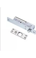
- WARNING TO THE INSTALLER AND USER
- Instruction
- Dimension
- Technical Specifications
- Installation
- Example of an installed automatic sliding gate
- Installation and adjustment
- XBS-CAN-AC-800 standard installation layout
- When the Operator is installed on Left Side.
- When the Operator is installed on Right Side.
- Dip-switch set up
- Running time programming
- Transmitter's code setting
- Erasing the transmitter's code
Brand : AccessPRO
Model : XBS-CAN-AC-800
Category : Gate automation