USER MANUAL BAC4255 Becken
MANUAL DE INSTRUÇÕES
BAC4255
BAC4255N
Dear client,
Thank you for purchasing this product.
The quality of this appliance has been certified by several laboratory tests. This instructions manual is provided to simplify the use of the appliance as well as to guarantee a safe use.
Please read carefully the instructions and safety measures described in this manual.
We sincerely hope you will be satisfied when using your new appliance.
INDEX
1. SAFETY INSTRUCTIONS 4
1.1. Power Supply 5
1.2. Power Cord and Other Cables 5
1.3. Humidity and Water 5
1.4. Cleaning 6
1.5. General Precautions 6
2. OPERATING INSTRUCTIONS 12
2.1. Product Description 12
2.2. Product Usage 12
2.3. Maintenance 53
2.4. Troubleshooting 55
2.5. Technical Specifications 56
3. POST-SALE SERVICE
57
4. ENVIRONMENTAL PROTECTION
57
1. SAFETY INSTRUCTIONS
 | WARNING |  |
| RISK OF ELECTRIC SHOCKDO NOT OPEN |
| Warning: to avoid the risk of electric shock, do not remove the cover. The interior does not contain any parts that can be repaired by the user. Ask for the Customer Support Service. |
Important Warnings
Before using your appliance read these instructions manual carefully and keep it in a safe place as you may need to consult it in the future.
Before turning on your appliance, and to ensure a safe and correct operation, do not use if:
- It has fallen to the ground;
- You notice any evidence of damage;
- Any anomaly occurs during its operation.
To avoid hazards or deterioration of your appliance through incorrect use it is advisable to read these instructions thoroughly.
Your appliance may not be used for other purposes than the ones intended and solely for household use. Any damage resulting from using the appliance outside this scope, any incorrect use, as well as any manual modifications to the product will not be covered and automatically voids the warranty.
[you can trust]
Assistance
In case of malfunction, take your appliance to the Customer Support Service for assistance.
This appliance can be used by children from the age of 8 and by people with reduced physical, sensorial or mental capabilities and/or lack of experience and knowledge if they have been given instructions on using the appliance safely and if they understand the hazards involved. Children may not play with the appliance. Cleaning and maintenance must not be carried out by children without supervision.
These instructions are also available at www.suporteworten.pt
1.1. Power Supply
Make sure the main voltage is compatible with the appliance's. If this is not the case, please consult the Customer Support Service.
1.2. Power Cord and Other Cables
Do not tangle the cord or pull it to disconnect the appliance. Also, keep the cord away from warm surfaces.
Never use the appliance if it has a damaged cable or socket.
Take it to the Customer Support Service for replacement.
1.3. Humidity and Water
Do not use your appliance in humid places. Do not allow the appliance to become wet under any circumstances as this may be dangerous. To avoid fire hazard or electric shock do not expose your appliance to humidity or water. Furthermore, do not place your appliance under water (e.g. for cleaning).
BECKEN
1.4. Cleaning
Before cleaning, be sure to switch off the appliance and remove the plug from the main power supply. Always allow the unit to cool down before cleaning.
To clean the exterior of the product, use a dry soft cloth only.
1.5. General Precautions
- Please follow the instructions in the user manual which will help you to properly install and operate this product and enjoy its advanced features. Please keep the instructions for future reference.
- Read all instructions before using the product.
- Maintenance and service operations are only to be carried out by authorized professionals.
- Any damage caused by manual modifications to the product is not covered by the warranty.
- If this product is used for other purposes than the ones originally intended, or if it is not correctly connected, the product may become damaged and the warranty will be voided.
- This symbol indicates that ignoring instructions may cause death or serious injury.
- Warning: To prevent death or injury to the user or other people and property damage, the following instructions must be followed. Incorrect operation due to ignoring of instructions may cause death, harm or damage.
- Installation must be performed according to the installation instructions. Improper installation can cause water leakage, electrical shock, or fire.
[you can trust]
- Use only the included accessories and parts, and specified tools for the installation. Using non-standard parts can cause water leakage, electrical shock, fire and injury or property damage.
- Make sure that the outlet you are using is grounded and has the appropriate voltage. The power cord is equipped with a three-prong grounding plug to protect against shock. Voltage information can be found on the nameplate of the unit.
- Your unit must be used in a properly grounded wall receptacle. If the wall receptacle you intend to use is not adequately grounded or protected by a time delay fuse or circuit breaker (the fuse or circuit breaker needed is determined by the maximum current of the unit. The maximum current is indicated on the nameplate located on unit), have a qualified electrician install the proper receptacle.
• Install the unit on a flat, sturdy surface. Failure to do so could result in damage or excessive noise and vibration.
- The unit must be kept free from obstruction to ensure proper function and to mitigate safety hazards.
- DO NOT modify the length of the power cord or use an extension cord to power the unit.
- DO NOT share a single outlet with other electrical appliances. Improper power supply can cause fire or electrical shock.
- DO NOT install your air conditioner in a wet room such as a bathroom or laundry room. Too much exposure to water can cause electrical components to short circuit.
- DO NOT install the unit in a location that may be exposed to combustible gas, as this could cause fire.
BECKEN
- The unit has wheels to facilitate moving. Make sure not to use the wheels on thick carpet or to roll over objects, as these could cause tipping.
- The appliance with electric heater shall have at least 1 meter space to the combustible materials.
- Do not touch the unit with wet or damp hands or when barefoot.
- If the air conditioner is knocked over during use, turn off the unit and unplug it from the main power supply immediately. Visually inspect the unit to ensure there is no damage. If you suspect the unit has been damaged, contact a technician or the Customer Support Service for assistance.
- During a thunderstorm, the power must be cut off to avoid damage to the machine due to lightning.
- Your air conditioner should be used in such a way that it is protected from moisture. e.g. condensation, splashed water, etc. Do not place or store your air conditioner where it can fall or be pulled into water or any other liquid. Unplug immediately if it occurs.
- All wiring must be performed strictly in accordance with the wiring diagram located inside of the unit.
- The unit's circuit board (PCB) is designed with a fuse to provide overcurrent protection. The specifications of the fuse are printed on the circuit board, such as: T 3.15A/250V, etc.
Cautions
- Do not remove any fixed covers. Never use this appliance if it is not working properly, or if it has been dropped or damaged.
- Do not run the cord under carpeting. Do not the cover cord with throw rugs, runners, or similar coverings. Do not route the cord
[you can trust]
under furniture or appliances. Arrange the cord away from traffic area and where it will not be tripped over.
- To reduce the risk of fire or electric shock, do not use this fan with any solid-state speed control device.
- The appliance shall be installed in accordance with national wiring regulations.
- Do not cover or obstruct the inlet or outlet grilles.
- Do not use this product for functions other than those described in this instruction manual.
- Disconnect the power if strange sounds, smell, or smoke comes from it.
- Do not press the buttons on the control panel with anything other than your fingers.
- Do not operate or stop the unit by inserting or pulling out the power cord plug.
- Do not use hazardous chemicals to clean or come into contact with the unit. Do not use the unit in the presence of inflammable substances or vapour such as alcohol, insecticides, petrol, etc.
• Always transport your air conditioner in a vertical position and stand it on a stable, level surface during use.
- Hold the plug by the head of the power plug when taking it out.
• Turn off the product when not in use.
Warnings
Do not use means to accelerate the defrosting process or to clean other than those recommended by the manufacturer.
- The appliance shall be stored in a room without continuously operating ignition sources (for example: open flames, an operating gas appliance or an operating electric heater)
- Do not pierce or burn.
- Be aware that refrigerants may not contain an odour.
- Appliance BAC4255 12BTUS should be installed, operated and stored in a room with a floor area larger than 11m^2 .
- Compliance with national gas regulations shall be observed.
- Keep ventilation openings clear of obstruction.
- The appliance shall be stored so as to prevent mechanical damage from occurring.
- A warning that the appliance shall be stored in a well-ventilated area where the room size corresponds to the room area as specified for operation.
- Any person involved with working on or breaking into a refrigerant circuit should hold a current valid certificate from an industry-accredited assessment authority, which authorises their competence to handle refrigerants safely in accordance with an industry recognised assessment specification.
- Servicing shall only be performed as recommended by the equipment manufacturer. Maintenance and repair requiring the assistance of other skilled personnel shall be carried out under the supervision of the person competent in the use of flammable refrigerants.
[you can trust]

Caution: Risk of fire/ flammable materials (Required for R32/R290 units only)

natural_image
Simple line drawing of an open book with no text or symbols visible
Important note: Read this manual carefully before installing or operating your new air conditioner unit. Make sure to save this manual for future reference
| Explanation of symbols displayed on the unit |
 | WARNING | This symbol shows that this unit uses a flammable refrigerant. If the refrigerant is leaked and exposed to an external ignition source, there is a risk of fire. |
 | CAUTION | This symbol shows that a service personnel should be handling this equipment with reference to the installation manual. |
 | CAUTION | This symbol shows that information is available such as the operating manual or installation manual. |
BECKEN
2. OPERATING INSTRUCTIONS
2.1. Product Description

2.2. Product usage
Warnings
- Transport of equipment containing flammable refrigerants. See transport regulations
- Marking of equipment using signs. See local regulations
- Disposal of equipment using flammable refrigerants. See national regulations.
- Storage of equipment/appliances.
The storage of equipment should be in accordance with the manufacturer's instructions.
- Storage of packed (unsold) equipment. Storage package protection should be constructed such that mechanical damage to the equipment inside the package will not cause a leak of the refrigerant charge.
[you can trust]
The maximum number of pieces of equipment permitted to be stored together will be determined by local regulations.
• Information on servicing
1. Area checks
Prior to beginning work on systems containing flammable refrigerants, safety checks are necessary to ensure that the risk of ignition is minimised. For repair to the refrigerating system, the following precautions shall be complied with prior to conducting work on the system.
2. Work procedure
Works shall be undertaken under a controlled procedure so as to minimise the risk of a flammable gas or vapour being present while the work is being performed.
3. General work area
All maintenance staff and others working in the local area shall be instructed on the nature of work being carried out. Work in confined spaces shall be avoided. The area around the work space shall be sectioned off. Ensure that the conditions within the area have been made safe by control of flammable material.
4. Checking for presence of refrigerant
The area shall be checked with an appropriate refrigerant detector prior to and during work, to ensure the technician is aware of potentially flammable atmospheres. Ensure that the leak detection equipment being used is suitable for use with flammable refrigerants, i.e. no sparking, adequately sealed or intrinsically safe.
5. Presence of fire extinguisher
If any hot work is to be conducted on the refrigeration equipment or any associated parts, appropriate fire extinguishing equipment shall be available on hand. Have a dry power or CO^2 fire extinguisher next to the charging area.
BECKEN
6. No ignition sources
No person carrying out work with a refrigeration system which involves exposing any pipe work that contains or has contained flammable refrigerant shall use any sources of ignition in such a manner that it may lead to risk of fire or explosion. All possible ignition sources, including cigarette smoking, should be kept sufficiently far away from the site of installation, repairing, removing and disposal, during which flammable refrigerant can possibly be released to the surrounding space. Prior to work taking place, the area around the equipment is to be surveyed to make sure that there are no flammable hazards or ignition risks. “NO SMOKING” signs shall be displayed.
7. Ventilated area
Ensure the work area is in the open or that it is adequately ventilated before breaking into the system or conducting any hot work. A degree of ventilation shall continue during the period that the work is carried out. The ventilation should safely disperse any released refrigerant and preferably expel it externally into the atmosphere.
8. Checks to the refrigeration equipment
Where electrical components are being changed, they shall be fit for the purpose and to the correct specification. At all times the manufacturer's maintenance and service guidelines shall be followed. If in doubt, consult the manufacturer's technical department for assistance. The following checks shall be applied to installations using flammable refrigerants:
- the charge size is in accordance with the room size within which the refrigerant containing parts are installed;
- the ventilation machinery and outlets are operating adequately and are not obstructed;
- if an indirect refrigerating circuit is being used, the secondary circuits shall be checked for the presence of refrigerant; marking to the equipment continues to be visible and legible.
[you can trust]
- marking and signs that are illegible shall be corrected;
- refrigeration pipe or components are installed in a position where they are unlikely to be exposed to any substance which may corrode refrigerant containing components, unless the components are constructed of materials which are inherently resistant to being
• corroded or are suitably protected against being so corroded.
9. Checks to electrical devices
Repair and maintenance to electrical components shall include initial safety checks and component inspection procedures. If a fault exists that could compromise safety, then no electrical supply shall be connected to the circuit until it is satisfactorily dealt with. If the fault cannot be corrected immediately but it is necessary to continue operation, and adequate temporary solution shall be used. This shall be reported to the owner of the equipment, so all parties are advised. Initial safety checks shall include:
- that capacitors are discharged: this shall be done in a safe manner to avoid possibility of sparking
- that there no live electrical components and wiring are exposed while charging, recovering or purging the system;
• that there is continuity of earth bonding.
10. Repairs to sealed components
10.1 During repairs to sealed components, all electrical supplies shall be disconnected from the equipment being worked upon prior to any removal of sealed covers, etc. If it is absolutely necessary to have an electrical supply to equipment during servicing, then a permanently operating form of leak detection shall be located at the most critical point to warn of a potentially hazardous situation.
BECKEN
10.2 Particular attention shall be paid to the following to ensure that by, working on electrical components, the casing is not altered in such a way that the level of protection is affected. This shall include damage to cables, excessive number of connections, terminals not made to original specification, damage to seals, incorrect fitting of glands, etc.
- Ensure that apparatus is mounted securely.
- Ensure that seals or sealing materials have not degraded in such a way that they no longer serve the purpose of preventing the ingress of flammable atmospheres. Replacement parts shall be in accordance with the manufacturer's specifications.
Note: the use of silicon sealant may inhibit the effectiveness of some types of leak detection equipment. Intrinsically safe components do not have to be isolated prior to working on them.
11. Repair to intrinsically safe components
Do not apply any permanent inductive or capacitance loads to the circuit without ensuring that this will not exceed the permissible voltage and current permitted for the equipment in use. Intrinsically safe components are the only types that can be worked on while live in the presence of a flammable atmosphere. The test apparatus shall be at the correct rating.
Replace components only with parts specified by the manufacturer. Other parts may result in the ignition of refrigerant in the atmosphere from a leak.
12. Cabling
Check that cabling will not be subject to wear, corrosion, excessive pressure, vibration, sharp edges or any other adverse environmental effects. The check shall also take into account the effects of aging or continual vibration from sources such as compressors or fans.
[you can trust]
13. Detection of flammable refrigerants
Under no circumstances shall potential sources of ignition be used when in the search for or detection of refrigerant leaks. A halide torch (or any other detector using a naked flame) shall not be used.
14. Leak detection methods
The following leak detection methods are deemed acceptable for systems containing flammable refrigerants. Electronic leak detectors shall be used to detect flammable refrigerants, but the sensitivity may not be adequate, or may need re-calibration (detection equipment shall be calibrated in a refrigerant-free area). Ensure that the detector is not a potential source of ignition and is suitable for the refrigerant. Leak detection equipment shall be set at a percentage of the LFL of the refrigerant and shall be calibrated to the refrigerant employed and the appropriate percentage of gas (25 % maximum) is confirmed. Leak detection fluids are suitable for use with most refrigerants but the use of detergents containing chlorine shall be avoided as the chlorine may react with the refrigerant and corrode the copper pipe-work.
If a leak is suspected, all naked flames shall be removed or extinguished. If a leakage of refrigerant is found which requires brazing, all of the refrigerant shall be recovered from the system, or isolated (by means of shut off valves) in a part of the system remote from the leak. Oxygen free nitrogen (OFN) shall then be purged through the system both before and during the brazing process.
15. Removal and evacuation
When accessing the refrigerant circuit to make repairs for any other purpose, conventional procedures shall be used. However, it is important that best practice is followed since flammability is a consideration. The following procedure shall be adhered to:
- remove refrigerant;
• purge the circuit with inert gas;
- evacuate;
BECKEN
• purge again with inert gas;
- open the circuit by cutting or brazing.
The refrigerant charge shall be recovered into the correct recovery cylinders. The system shall be flushed with OFN to render the unit safe. This process may need to be repeated several times. Compressed air or oxygen shall not be used for this task.
Flushing shall be achieved by breaking the vacuum in the system with OFN and continuing to fill it until the working pressure is achieved, then venting to atmosphere, and finally pulling down to a vacuum. This process shall be repeated until no refrigerant is in the system.
When the final OFN charge is used, the system shall be vented down to atmospheric pressure to enable work to take place. This operation is absolutely vital if brazing operations on the pipe-work are to take place. Ensure that the outlet for the vacuum pump is not closed to any ignition sources and there is ventilation available.
16. Charging procedures
In addition to conventional charging procedures, the following requirements shall be followed:
- Ensure that contamination of different refrigerants does not occur when using charging equipment. Hoses or lines shall be as short as possible to minimize the amount of refrigerant contained in them.
• Cylinders shall be kept upright.
- Ensure that the refrigeration system is earthed prior to charging the system with refrigerant.
- Label the system when charging is complete (if not already).
- Extreme care shall be taken not to overfill the refrigeration system.
- Prior to recharging the system it shall be pressure tested with OFN. The system shall be leak tested on completion of charging but prior
[you can trust]
to commissioning. A follow up leak test shall be carried out prior to leaving the site.
17. Decommissioning
Before carrying out this procedure, it is essential that the technician be completely familiar with the equipment and all its detail. It is recommended good practice that all refrigerants are recovered safely. Prior to the task being carried out, an oil and refrigerant sample shall be taken.
In case analysis is required prior to re-use of reclaimed refrigerant. It is essential that electrical power is available before the task is commenced.
a) Become familiar with the equipment and its operation.
b) Isolate system electrically
c) Before attempting the procedure ensure that:
- mechanical handling equipment is available, if required, for handling refrigerant cylinders;
- all personal protective equipment is available and being used correctly;
- the recovery process is supervised at all times by a competent person;
- recovery equipment and cylinders conform to the appropriate standards.
d) Pump down refrigerant system, if possible.
e) If a vacuum is not possible, make a manifold so that refrigerant can be removed from various parts of the system.
f) Make sure that cylinder is situated on the scales before recovery takes place.
BECKEN
g) Start the recovery machine and operate in accordance with manufacturer's instructions.
h) Do not overfill the cylinders (no more than 80 % of the volume liquid charge).
i) Do not exceed the maximum working pressure of the cylinder, even temporarily.
j) When the cylinders have been filled correctly and the process completed, make sure the cylinders and the equipment are removed from the site promptly and all isolation valves on the equipment are closed off.
k) Recovered refrigerant shall not be charged into another refrigeration system unless it has been cleaned and checked.
18. Labelling
Equipment shall be labelled stating that it has been de-commissioned and emptied of refrigerant. The label shall be dated and signed. Ensure that there are labels on the equipment stating the equipment contains flammable refrigerant.
19. Recovery
- When removing refrigerant from a system, either for service or decommissioning, it is recommended good practice that all refrigerants be removed safely.
- When transferring refrigerant into cylinders, ensure that only appropriate refrigerant recovery cylinders are used. Ensure that the correct numbers of cylinders for holding the total system charge are available. All cylinders to be used are designated for the recovered refrigerant and labelled for that refrigerant (i.e. special cylinders for the recovery of refrigerant). Cylinders shall be complete with pressure relief valve and associated shut-off valves in good working order.
[you can trust]
- Empty recovery cylinders are evacuated and, if possible, cooled before recovery occurs. The recovery equipment shall be in good working order with a set of instructions concerning the equipment that is at hand and shall be suitable for the recovery of flammable refrigerants. In addition, a set of calibrated weighing scales shall be available and in good working order.
- Hoses shall be complete with leak-free disconnect couplings and in good condition. Before using the recovery machine, check that it is in satisfactory working order, has been properly maintained and that any associated electrical components are sealed to prevent ignition in the event of a refrigerant release. Consult the manufacturer if in doubt.
- The recovered refrigerant shall be returned to the refrigerant supplier in the correct recovery cylinder, and the relevant Waste Transfer Note arranged. Do not mix refrigerants in recovery units and especially not in the cylinders.
- If compressors or compressor oils are to be removed, ensure that they have been evacuated to an acceptable level to make sure that flammable refrigerant does not remain within the lubricant. The evacuation process shall be carried out prior to returning the compressor to the suppliers. Only electric heating to the compressor body shall be employed to accelerate this process. When oil is drained from a system, it shall be carried out safely.
Note About Fluorinated Gasses
- Fluorinated greenhouse gases are contained in hermetically sealed equipment. For specific information on the type, the amount and the CO^2 equivalent in tonnes of the fluorinated greenhouse gas (on some models), please refer to the relevant label on the unit itself.
• Installation, service, maintenance and repair of this unit must be performed by a certified technician.
BECKEN
- Product uninstallation and recycling must be performed by a certified technician.
Installation
Choosing The Right Location
Your installation location should meet the following requirements:
- Make sure that you install your unit on an even surface to minimize noise and vibration.
- The unit must be installed near a grounded plug, and the Collection Tray Drain (found on the back of the unit) must be accessible.
- The unit should be located at least 30cm (12") from the nearest wall to ensure proper air conditioner.
- DO NOT cover the Intakes, Outlets or Remote Signal Receptor of the unit, as this could cause damage to the unit.
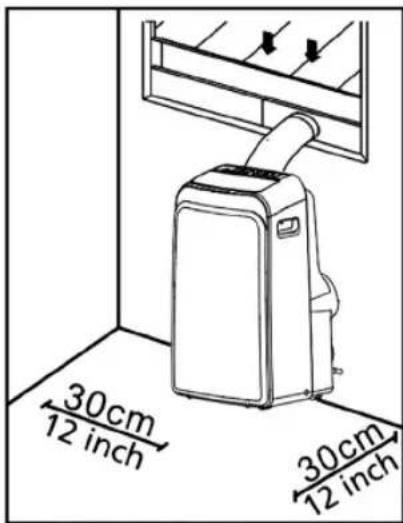
Recommend installation
Note: All the illustrations in the manual are for explanation purpose only. Your machine may be slightly different.
The unit can be controlled by the unit control panel alone or with the remote controller.

- Medium Philips screwdriver;
- Tape measure or ruler
- Knife or scissors;
- Saw (optional, to shorten window adaptor for narrow windows)
[you can trust]
Accessories
Check your window size and choose the fit window slider
| Part Description Quantity |
 | Unit Adaptor 1 | pc Bolt 1 pc | 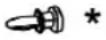 | | |
 | Exhaust Hose 1 | pc Security | 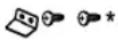 | Bracket and Screw | 1 set |
 | Window Slider Adaptor | 1 pc Drain Hose 1 pc  | | | |
|
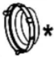 | Wall Exhaust Adaptor A (only for wall installation) | 1 pc | 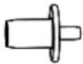 | Drain Hose Adaptor (only for heat pump mode) | 1 pc |
 | Wall Exhaust Adaptor B (with cap) (only for wall installation) | 1 pc Foam Seal A  | | (Adhesive) | 2 pc |
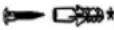 | Screw and anchor (only for wall installation) | 4 set Foam Seal B  | | (Adhesive) | 2 pc |
 | Window Slider A | 1 pc Foam Seal  | | (Non-adhesive) | 1 pc |
 | Window Slider B | 1 pc | 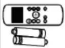 | Remote Controller and Battery | 1 set |
 | Power Cord Buckle | 1 pc |
Note: Items with * are optional. Slight variations in design may occur.
BECKEN
Window Installation Kit
Step One: Preparing the exhaust hose assembly
Press the exhaust hose into the window slider adaptor and unit adaptor, clamp automatically by elastic buckles of the adaptors.

Step Two: Install the exhaust hose assembly to the unit
Insert the unit adaptor of the Exhaust hose assembly into the lower groove of the unit's air outlet with the adaptor's hook aligned with the hole seat of the air outlet and slide down the exhaust hose assembly along the arrow direction for installation.

Step Three: Preparing the adjustable window slider
- Depending on your window's size, adjust the window slider's size.
- If the length of the window requires two window sliders, use the bolt to fasten the window sliders once they are adjusted to the proper length.
[you can trust]
- For some models, if the length of the window requires three window sliders (optional), use two bolts to fasten the window sliders once they are adjusted to proper length.

Note: once the exhaust hose assembly and adjustable window slider are prepared, choose from one of the following installation methods.
Method 1: Hung Window or Sliding Window Installation (optional)
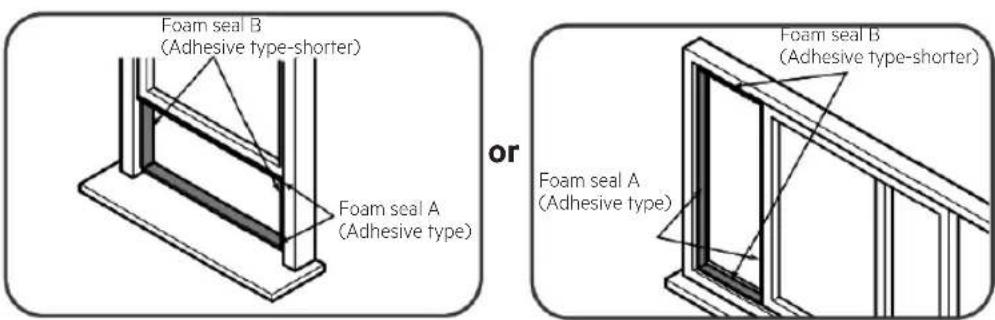
- Cut the adhesive foam seal A and B strips to the proper lengths, and attach them to the window sash and frame as shown.
BECKEN

- Insert the window slider assembly into the window opening.

- Cut the non-adhesive foam seal C strip to match the width of the window. Insert the seal between the glass and the window frame to prevent air and insects from getting into the room.

- If desired, install the security bracket with 2 screws as shown.
[you can trust]

natural_image
Two-panel illustration showing a device with a coiled hose connected to a window, labeled 'or' (no text or symbols on the devices themselves)
- Insert the window slider adaptor into the hole of the window slider.
Method 2: Wall Installation (optional)
- Cut a 125 mm (4.9 inch) hole into the wall for the wall exhaust adaptor B.
- Secure the wall exhaust adaptor B to the wall using the four anchors and screws provided in the kit.
- Connect the exhaust hose assembly(with wall exhaust adaptor A) to the wall exhaust adaptor B.
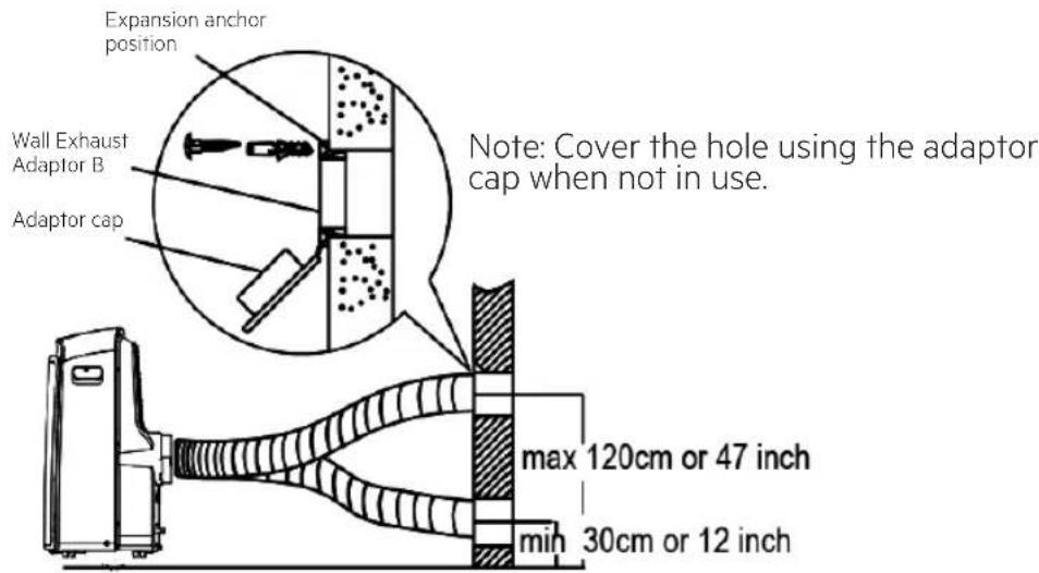
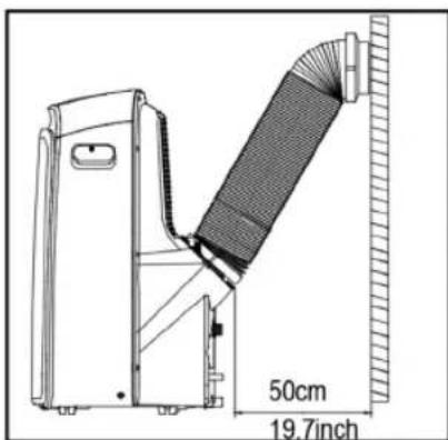
Note: to ensure proper function, DO NOT overextend or bend the hose. Make sure that there is no obstacle around the air outlet of the exhaust hose (in the range of 500 mm) in order to the exhaust system works properly. All figures in this manual are for illustrations purposes only. Your air conditioner may be slightly different, but the general shape will remain the same..
natural_image
Abstract black-and-white line drawing of intertwined loops (no text or symbols)

natural_image
Hand-drawn sketch of a coiled rope or tube with no text or symbols
Control Panel Operation
Note: the control panel may be look like one of the followings:
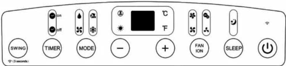
Note: on some models 🔒 is instead of °F. On some models ⚙ (WIRELESS light) is instead of • (power light).
Note: some features (ION, FOLLOW ME, HEAT, WIRELESS etc.) are optional. ION is not applicable for R32/R290 units
 | HEAT mode light |  | HIGH fan speed light | ### | FOLLOW ME light |
 | COOL mode light |  | MED fan speed light | ### | ION light |
 | FAN mode light |  | LOW fan speed light | ### | SLEEP light |
 | DRY mode light |  | AUTO fan speed light | ### | Degrees Celsius |
 | AUTO mode light |  | FILTER light | ### | Degrees Fahrenheit |
 | WIRELESS light |  | POWER MANAGEMENT light |  | LED display |
[you can trust]
Used to initiate the Auto swing feature. When the operation is ON, press the SWING button can stop the louver at the desired angle.

Used to initiate the Wireless function. When you use the Wireless function for the first time, press and hold the swing button for 3 seconds to initiate the Wireless connection mode. The LED DISPLAY shows 'AP' to indicate you can set the Wireless connection. If the connection (router) is successful within 8 minutes, the unit will exit the Wireless connection mode automatically and the Wireless indicator illuminates. If the connection fails within 8 minutes, the unit exits the Wireless connection mode automatically. After the Wireless connection is successful, you can press and hold the SWING and DOWN (-) buttons at the same time for 3 seconds to turn off the Wireless function and the LED DISPLAY shows 'OFF' for 3 seconds, press SWING and UP(+) buttons at the same time to turn the Wireless function on and the LED DISPLAY shows 'ON' for 3 seconds.
Note: when you restart the Wireless function, it may take a while to connect to the network automatically.
Used to initiate the AUTO ON start time and AUTO OFF stop time program, together with the + & - buttons. The timer on/off indicator light illuminates under the timer on/off settings.
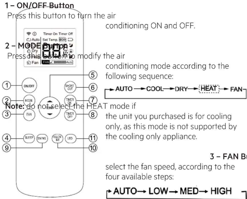
Selects the appropriate operating mode. Each time you press the button, a mode is selected in a sequence between AUTO, COOL, DRY, FAN and HEAT (cooling-only models do not have this mode).
The mode indicator light illuminates under the different mode settings.
■ Used to adjust (increasing/decreasing) temperature settings in 1°C / 1°F (or 2°F) increments in a range of 17°C / 62°F to 30°C / 86°F (or 88°F) or the TIMER setting in a range of 0\~24hrs.
Note: the control is capable of displaying temperature in degrees Fahrenheit or degrees Celsius. To convert from one to the other, press and hold the Up and Down buttons at the same time for 3 seconds.
FAN Fan/lon button (lon is optional)
ION Control the fan speed. Press to select the fan speed in four steps-LOW, MED, HIGH and AUTO. The fan speed indicator light illuminates under different fan settings. When select AUTO fan speed, all the fan indicator lights turn dark. On some models, when select AUTO fan speed, all the fan indicator lights illuminate (optional).
Note: press this button for 3 seconds to start the ION feature. The ion generator is energized and will help to remove pollen and impurities from the air, and trap them in the filter. Press it for 3 seconds again to stop the ION feature.
SLEEP Sleep (Eco) button
Used to initiate the SLEEP/ECO feature.

On/Off Power button

LED display
Iws the set temperature in °C or °F (some models do not display temperature in “°F”) and the Auto-timer settings. While on DRY and FAN modes, it shows the room temperature.
Shows Error codes and protection code:
E1 - Room temperature sensor error.
E2 - Evaporator temperature sensor error.
[you can trust]
E3 - Condenser temperature sensor error (on some models).
E4 - Display panel communication error.
EC - Refrigerant leakage detection malfunction (on some models).
P1 – Bottom tray is full – Connect the drain hose and drain the collected water away. If protection repeats, call for service.
Note: when one of the above malfunctions occur, turn off the unit and check for any obstructions. Restart the unit and if the malfunction is still present, turn off the unit and unplug the power cord. Contact the manufacturer or its service agents or a similar qualified person for service.
BECKEN
- The buttons design is based on standard models and might be slightly different from the actual one you purchase. However, the remote's actual shape will be the same.
- All functions described can be performed by this unit. If the unit cannot perform this feature, nothing happens when you press the corresponding button on the remote control.

[you can trust]
flowchart
graph TD
    A["1 - ON/OFF Button"] --> B["Press this button to turn the air"]
    B --> C["2 - MODE Button"]
    C --> D["Press this button to modify the air"]
    D --> E["3 - FAN Button"]
    E --> F["3 - MODE Button"]
    F --> G["NOTE: do not select the HEAT mode if"]
    G --> H["4 - Sleep"]
    G --> I["5 - Short Cut"]
    G --> J["6 - TIMER ON"]
    G --> K["7 - TIMER OFF"]
    G --> L["8 - LED"]
    G --> M["9 - FOLLOW ME"]
    G --> N["10 - AUTO → LOW → MED → HIGH"]
    style A fill:#f9f,stroke:#333
    style C fill:#ccf,stroke:#333
    style E fill:#cfc,stroke:#333
Note: you cannot change the fan speed
when in AUTO or DRY modes.
- Press this button to Activate/Deactivate the sleep function. It can stay at the most comfortable temperature and save energy. This function is available on COOL, HEAT or AUTO mode only.
- For further information, refer to SLEEP mode section.
Note: while the unit is running under SLEEP mode, this mode is cancelled if any of the MODE, FAN SPEED or ON/OFF buttons are pressed.
BECKEN
Press this button to raise the indoor temperature setting in 1^ C increments to 30^ C.
Press this button to lower the indoor temperature setting in 1^ C increments to 17^ C.
Note: temperature control is not available in FAN mode.
- Press this button to restore the current settings or resume previous settings.
- When powering the unit for the first time, pushing the SHORTCUT button will make the unit run on AUTO mode, at 26°C, at AUTO fan speed.
- Pressing this button when the remote control is on will make the system automatically revert to the previous settings including operating mode, setting temperature, fan speed level and sleep feature (if activated).
- Pressing this button for more than 2 seconds will make the system automatically restore the current operation settings including operating mode, setting temperature, fan speed level and sleep feature (if activated).
Press this button to start the auto-on timer sequence. Each press will increase the auto-time setting in 30-minute increments. When the setting time displays 10.0, each press will increase the auto-timed setting in 60-minute increments. To cancel the auto-time program, simply adjust the auto-on timer to 0.0.
[you can trust]
Press this button to start the auto-off timer sequence. Each press will increase the auto-time setting in 30-minute increments. When the setting time displays 10.0, each press will increase the auto-time setting in 60-minute increments. To cancel the auto-time program, simply adjust the auto-off timer to 0.0
Press this button to stop or start the horizontal auto swing fan feature or set the desired up/down air flow direction. The auto swing fan angles change by 6 degrees with each press. If the swing button is pressed continuously for more than 2 seconds, the feature is activated and will swing up and down automatically.
Press this button to Activate/Deactivate the Follow Me feature; the remote will display your location's current temperature. The remote control will send this signal to the air conditioning at 3-minute intervals until you press the Follow Me button again. The air conditioning will cancel the Follow Me feature automatically if it does not receive a signal at any 7 minutes intervals.
Press this button to Activate/Deactivate the indoor screen display. When pressing the button, the indoor screen display is cleared; pressing it again will light up the display.
Information are displayed when the remote control is powered up.

Mode display
AUTO COOL DRY HEAT
Displayed when data transmitted
① Displayed when remote control is ON
Battery display (low battery detection)
ECO Not available for this unit
TIMER ON Displayed when TIMER ON time is set
TIMER OFF Displayed when TIMER OFF time is set
Show set temperature, room temperature or timer under TIMER setting
Displayed when in Sleep Mode
# Displayed when in Follow me mode
Not available for this unit
Not available for this unit
[you can trust]
Fan speed indication

Note: All symbols in the figure are for illustration purposes only. During the actual operation, the display only shows the function symbols in use.
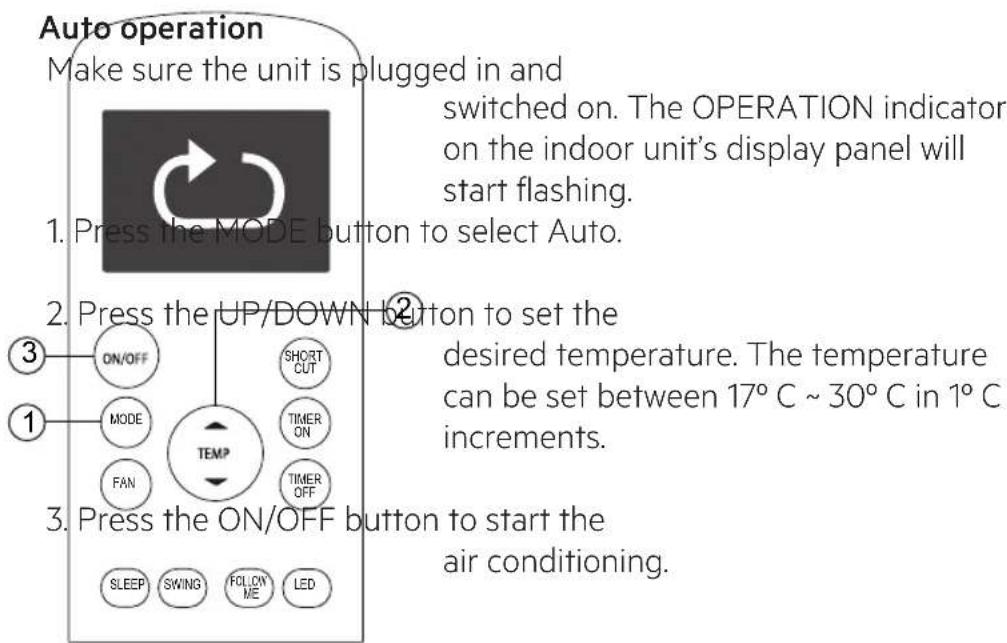
Note:
- In the AUTO mode, the air conditioning can automatically choose the Cooling, Fan or Heating mode by sensing the difference between the current ambient room temperature and the set temperature on the remote control.
BECKEN
- In the AUTO mode, you cannot change the fan speed, as this is automatically controlled.
- If the AUTO mode is not comfortable for you, you can choose another, more comfortable mode manually.
Cooling /Heating/Fan operation
Make sure the unit is plugged in and

switched on.
- Press the MODE button to select
COOL, HEAT (available in cooling & heating models only) or FAN mode.
- Press the UP/DOWN buttons to set the
desired temperature. The temperature can be set between 17^ C \~ 30^ C in 1^ C increments.
- Press the FAN button to select the fan
speed in four steps - Auto, Low, Med or High.

- Press the ON/OFF button to start the air conditioning.
Note: In the FAN mode, the set temperature is not displayed in the remote control and you are also unable to control the room temperature. In this case, only step 1, 3 and 4 may be performed.
Dehumidifying operation
Make sure the unit is plugged in and

switched on. The OPERATION indicator on the indoor unit's display panel will start flashing.
- Press the MODE button to select DRY mode.
③2. Press the UP/DOWN buttons to set the
desired temperature. The temperature can be set between 17^ C \~ 30^ C in 1^ C increments.
- Press the ON/OFF button to start the air conditioning.
Note:
In the Dehumidifying mode, you cannot change the fan speed, as this is automatically controlled.
Adjusting air flow direction
Use the SWING ◀▶ & 🔵 buttons to adjust the desired airflow direction.
-
Up/Down direction can be adjusted with the button on the remote control. The auto swing fan angles change by 6 degrees with each press. If the swing button is pressed continuously for more than 2 seconds, the feature is activated and will swing up and down automatically.
-
Left/Right direction can be adjusted with the ◀ button on the remote control. The auto swing fan angles change by 6 degrees with each press. If the swing button is pressed continuously for more than 2 seconds, the feature is activated and will swing up and down automatically.
Note: when the swing fan or its air direction affects the cooling or heating of the air conditioning, it will automatically change the swing/direction.
BECKEN
Timer operation
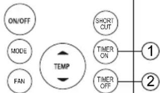
Press the TIMER
N button to set the unit's
auto-on timer. Press the TIMER OFF button to set the unit's auto-off timer.
Timer on
To set the Auto-on
timer.
- Press the TIMER
flowchart
graph TD
    A["ON/OFF"] --> B["MODE"]
    B --> C["FAN"]
    C --> D["TEMP"]
    D --> E["SHORT CUT"]
    E --> F["TIMER ON"]
    F --> G["1"]
    F --> H["2"]
ON button. The remote
control's LCD will show TIMER ON, the last Auto-on set time and the signal "H". It is now ready to reset the Auto-on timer to START the operation.
- Press the TIMER
ON button again to
set the desired Auto-on timer. The timer increases in 30-minute increments between 10 and 24 hours.
- After setting the TIMER ON, there will be a 1 second delay before the remote control transmits the signal to the air conditioning unit. Then, after approximately another 2 seconds, the signal "H" will disappear and the set temperature will re-appear on the LCD display window.
To set the Auto-off timer.
- Press the TIMER OFF button. The remote control's LCD will show TIMER OFF, the last Auto-off setting time and the signal "H". Now it is ready to reset the Auto-off timer to stop the operation.
- Press the TIMER OFF button again to set the desired Auto-off timer. The timer increases in 30-minute increments between 10 and 24 hours and in 1-hour increments between 10 and 24 hours.
- After setting the TIMER OFF, there will be a 1 second delay before the remote control transmits the signal to the air conditioning unit. Then, after approximately another 2 seconds, the signal "H" will disappear and the set temperature will re-appear on the LCD display window.
[you can trust]

CAUTION
- When you select the timer operation, the remote control automatically transmits the timer signal to the indoor unit for the specified time. Therefore, keep the remote control in a location where it can properly transmit the signal to the indoor unit.
- The timer function set by the remote control is limited to the following settings: 0.5, 1.0, 1.5, 2.0, 2.5, 3.0, 3.5, 4.0, 4.5, 5.0, 5.5, 6.0, 6.5, 7.0, 7.5, 8.0, 8.5, 9.0, 9.5, 10, 11, 12, 13, 14, 15, 16, 17, 18, 19, 20, 21, 22, 23 and 24.
Example of a timer setting

TIMER ON
(Auto-on Operation)
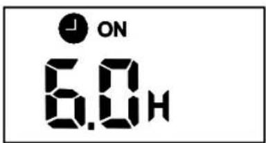
The TIMER ON feature is useful when you want the unit to turn on automatically before you return home. The air conditioning will automatically start operating at the set time.
To start the air conditioning within 6 hours, proceed accordingly:
- Press the TIMER ON button. The last setting of operation start and the signal "H" will show on the display area.
- Press the TIMER ON button to display "6.0H" on the remote control's TIMER ON display.
- Wait 3 seconds. The digital display area will show the temperature again. The “TIMER ON” indicator will remain on and this function is activated.


Set 10 hours later
TIMER OFF
(Auto-off Operation)
The TIMER OFF feature is useful when you want the unit to turn off automatically after you go to bed. The air conditioning will stop automatically at the set time.
Example:
To stop the air conditioning within 10 hours, proceed accordingly:
- Press the TIMER OFF button. The last setting of operation stop and the signal "H" will show on the display area.
- Press the TIMER OFF button to display "10H" on the remote control's TIMER OFF display.
[you can trust]
- Wait 3 seconds. The digital display area will show the temperature again. The "TIMER OFF" indicator will remain on and this function is activated.


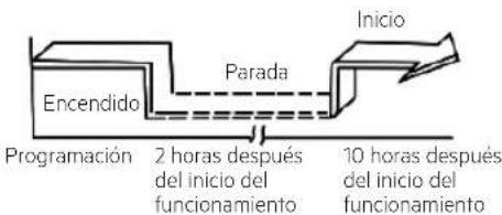
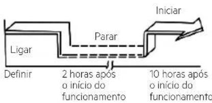
COMBINED TIMER (Setting both ON and OFF timers simultaneously)
(On → Stop → Start operation)
This feature is useful when you want to stop the air conditioning after you go to bed, and start it again in the morning when you wake up or when you return home.
Example:
To stop the air conditioning 2 hours after operation start and restart it 10 hours after.
-
Press the TIMER OFF button.
-
Press the TIMER OFF button again to display "2.0H" on the TIMER OFF display.
-
Press the TIMER ON button.
-
Press the TIMER ON button again to display "10H" on the TIMER ON display.
BECKEN
- Wait 3 seconds. The digital display area will show the temperature again. The "TIMER ON OFF" indicator will remain on and this function is activated.


flowchart
graph TD
    A["Start"] --> B["Set"]
    B --> C["2 hours later after setting"]
    C --> D["5 hours later after setting"]
    D --> E["StopOff"]
(Off → Start → Stop operation)
This feature is useful when you want to start the air conditioning before you wake up and stop it after you leave the house.
Example:
To start the air conditioning 2 hours after operation start, and stop it 5 hours after.
-
Press the TIMER ON button.
-
Press the TIMER ON button again to display "2.0H" on the TIMER ON display.
-
Press the TIMER OFF button.
-
Press the TIMER OFF button again to display "5.0H" on the TIMER OFF display.
-
Wait 3 seconds. The digital display area will show the temperature again. The "TIMER ON & TIMER OFF" indicator will remain on and this function is activated.
[you can trust]
Handling the remote control
Location of the remote control.
- Use the remote control within 8 meters from the unit, pointing it towards the receiver. Reception is confirmed by a beep.
CAUTION
- The air conditioning will not operate if curtains, doors or other materials block the signals from the remote control to the indoor unit.
- Prevent any liquid from falling into the remote control. Do not expose the remote control to direct sunlight or heat.
- If the infrared signal receiver on the indoor unit is exposed to direct sunlight, the air conditioning may not function properly. Use curtains to prevent the signal receiver from being under direct sunlight.
- If other electrical appliances react to the remote control, either move these appliances or consult your local dealer.
- Do not drop the remote control. Handle with care.
- Do not place heavy objects on the remote control, or step on it.
natural_image
Diagram showing a remote control device with an open rear panel and a close-up of its internal components (no text or symbols)
Using the remote control holder (optional)
- The remote control can be attached to a wall or pillar by using a remote control holder (not supplied, purchased separately).
- Before installing the remote control, check the air conditioning receives the signals properly.
• Install the remote control holder with two screws.
- To install or remove the remote control, move it up or down in the holder.

natural_image
Diagram of a device's internal components and battery assembly (no text or symbols)
Replacing the batteries
Replace the old batteries with new ones when the following cases, which signify exhausted batteries, occur:
• There is no beep sound when a signal is transmitted.
• Received indicator fades away.
[you can trust]
The remote control is powered by 2 dry batteries (R03/LR03X2) in the back part of the remote, protected by a cover.
- Remove the cover in the back part of the remote control.
- Remove the old batteries and insert the new batteries, placing the (+) and (-) poles correctly.
- Place the cover back on.
Note: When the batteries are removed, the remote control erases all programming. After inserting new batteries, the remote control must be reprogrammed.
CAUTION
- Do not mix old and new batteries or different types of batteries.
- Do not leave the batteries in the remote control if they are not going to be used for 2 or 3 months.
- Do not dispose of batteries as unsorted municipal waste. It is necessary to collected such waste separately for special processing.
Exhaust hose installation
The exhaust hose and adaptor must be installed or removed in accordance with the usage mode.
For COOL, HEAT (heat pump type) or AUTO modes, the exhaust hose must be installed.
For FAN, DEHUMIDIIFY or HEAT (electrical heat type) modes, the exhaust hose must be removed.
BECKEN
Operation Instructions
COOL operation
- Press the MODE button until the COOL indicator light comes on.
- Press the ADJUST buttons “+” or “-” to select your desired room temperature. The temperature can be set within a range of 17^ C \~ 30^ C / 62^ F \~ 86^ F (or 88^ F).
- Press the FAN SPEED button to choose the fan speed.
HEAT operation
- Press the MODE button until the HEAT indicator light comes on.
- Press the ADJUST buttons “+” or “-” to select your desired room temperature. The temperature can be set within a range of 17^ C \~ 30^ C / 62^ F \~ 86^ F (or 88^ F).
- Press the FAN SPEED button to choose the fan speed.
In some models, the fan speed cannot be adjusted under the HEAT mode.
DRY operation
- Press the MODE button until the DRY indicator light comes on.
- Under this mode, you cannot select a fan speed or adjust the temperature. The fan motor operates at LOW speed.
- Keep windows and doors closed for the best dehumidifying effect.
- Do not duct tape the window.
AUTO operation
- When you set the air conditioner to AUTO mode, it will automatically select cooling, heating (cooling-only models do not present this feature), or fan only operation depending on what temperature you have selected and the room temperature itself.
- The air conditioner will control the room temperature automatically to match the temperature you set.
- Under the AUTO mode, you cannot select the fan speed.
Note: under the AUTO mode, both the AUTO mode and the actual operation mode indicator lights show in some models.
[you can trust]
FAN operation
- Press the MODE button until the FAN indicator light comes on.
- Press the FAN SPEED button to choose the fan speed.
The temperature cannot be adjusted.
- Do not duct tape the window.
TIMER operation
- When the unit is on, press the TIMER button will start the Auto-off stop program; the TIMER OFF indicator light illuminates. Press the UP or DOWN button to set the timer. Press the TIMER button again within 5 seconds and the Auto-on start program is initiated.
And the TIMER ON indicator light illuminates. Press the UP or DOWN button to select the desired Auto-on start time.
- When the unit is off, press the TIMER button to initiate the Auto-on start program. Press it again within 5 seconds to and then Auto-off stop program is initiated.
- Press or hold the UP or DOWN button to change the Auto time by 0.5 hour increments, up to 10 hours, then at 1 hour increments up to 24 hours. The control will count down the time remaining until start.
- The system will automatically revert back to display the previous temperature setting if there is no operation in a 5 seconds period.
- Turning the unit ON or OFF at any time or adjusting the timer setting to 0.0 will cancel the Auto Start/Stop timer program.
SLEEP(ECO) operation
- Press this button and the selected temperature will increase (cooling) or decrease (heating) by 1^ C / 2^ F (or 1^ F) 30 minutes.
The temperature will then increase (cooling) or decrease (heating) by another 1^ C / 2^ F (or 1^ F) after an additional 30 minutes.
This new temperature will be maintained for 7 hours before it returns to the originally selected temperature. This ends the Sleep/Eco mode and the unit will continue to operate as originally programmed.
Note: This feature is unavailable under the FAN or DRY modes.
BECKEN
Other features
FOLLOW ME/TEMP. SENSING feature
Note: this feature can be activated from the remote control ONLY. The remote control serves as a remote thermostat allowing for the precise temperature control at its location. To activate the Follow Me/Temp. Sensing feature, point the remote control towards the unit and press the Follow Me/Temp. Sensing button. The remote control will send this signal to the air conditioner until press the Follow Me/Temp. Sensing button again. If the unit does not receive the Follow Me/Temp. Sensing signal during any 7 minutes interval, the unit will exit the Follow Me/Temp. Sensing mode.
Note: this feature is unavailable under the FAN or DRY modes.
AUTO-RESTART
If the unit breaks off unexpectedly due to the power cut, it will restart with the previous function setting automatically when the power resumes.
AIR FLOW DIRECTION ADJUSTMENT
The louver can be adjusted automatically. Adjust the air flow direction automatically:
- When the Power is ON, the louver opens fully.
- Press the SWING button on the panel or remote controller to initiate the Auto swing feature. The louver will swing up and down automatically.
- Please do not adjust the louver manually.
WAIT 3 MINUTES BEFORE RESUMING OPERATION
After the unit has stopped or turned off accidentally, its operation cannot restart for 3 minutes. This happens in order to protect the unit. Operation will automatically resume after 3 minutes.
POWER MANAGEMENT feature (on some models)
When the ambient temperature is lower than the setting temperature for a period of time, the unit will automatically start the power management feature. The compressor and fan motor stop.
[you can trust]
When the ambient temperature is higher than the setting temperature, the unit will automatically stop the power management feature.
The compressor and (or) fan motor will resume.
Note: for units with power management light, the light will illuminate under this feature.
Water drainage
- In dehumidifying modes, remove the upper drain plug from the back of the unit, install the drain connector (5/8" universal female mender) with 3/4" hose (locally purchased). For models without a drain connector, just attach the drain hose to the hole. Place the open end of the hose directly over the drain area in your basement floor.

- In heating pump mode, remove the lower drain plug from the back of the unit, install the drain connector (5/8" universal female mender) with 3/4" hose (locally purchased). For the models without drain connector, just attach the drain hose to the hole. Place the open end of the Hose adaptor directly over the drain area in your basement floor.
Note: make sure the hose is secure so there are no leaks.
Direct the hose toward the drain, making sure that there are no kinks that will stop the water flow. Place the end of the hose into the drain and make sure the end of the hose is down to let the water flow smoothly.
(See Figs with ☑Do never let it up.(See Figs with ).When the continuous drain hose is not used, ensure that the corresponding drain plug and knob are installed firmly to prevent leakage.

When the water level of the bottom tray reaches a predetermined level, the unit beeps 8 times and the digital display shows "P1". At this time, the air conditioner/dehumidification process will immediately stop. However, the fan motor will continue to operate (this is normal). Carefully move the unit to a drain location, remove the bottom drain plug and let the water drain away. Reinstall the bottom drain plug and restart the machine until the "P1" symbol disappears. If the error repeats, call the Customer Support Service.
Note: be sure to reinstall the bottom drain plug firmly to prevent leakage before using the unit.
[you can trust]
2.3. Maintenance
Warnings:
• Always unplug the unit before cleaning or servicing.
- DO NOT use flammable liquids or chemicals to clean the unit.
- DO NOT wash the unit under running water. Doing so causes electrical danger.
- DO NOT operate the machine if the power supply was damaged during cleaning. A damaged power cord must be replaced with a new cord from the manufacturer.
Clean the Air Filter
- Remove the air filter.

- Clean the air filter with a hand-held vacuum.
- Clean the grill with warm, soapy water. Be sure to use a mild detergent.
Caution
DO NOT operate the unit without filter because dirt and lint will clog it and reduce performance.
- Be sure to clean the air filter every 2 weeks for optimal performance.
- The water collection tray should be drained immediately after P1 error occurs, and before storage to prevent mold.
- In households with animals, you will have to periodically wipe down the grill to prevent blocked airflow due to animal hair.
Clean the unit
Clean the unit using a damp, lint-free cloth and mild detergent. Dry the unit with a dry, lint-free cloth.
Store the unit when not in use
- Drain the unit's water collection tray according to the instructions in the following section.
- Run the appliance on the FAN mode for 12 hours in a warm room to dry it and prevent mold.
- Turn off the appliance and unplug it.
- Clean the air filter according to the instructions in the previous section. Reinstall the clean, dry filter before storing.
- Remove the batteries from the remote control. Be sure to store the unit in a cool, dark place. Exposure to direct sunshine or extreme heat can shorten the unit's lifespan.
Note: the cabinet front may be dusted with an oil-free cloth or washed with a cloth dampened in a solution of warm water and mild liquid dishwashing detergent. Rinse thoroughly and wipe dry. Never use harsh cleansers, wax or polish on the cabinet front. Be sure to wring excess water from the cloth before wiping around the controls. Excess water in or around the controls may cause damage to the unit.
[you can trust]
2.4. Troubleshooting
Refer to the table below before asking for maintenance.
| Problem Possible Cause Troubleshooting | |
| The unit does not turn on when ON/OFF button is pressed | P1 Error Code The Water collection tray is full. Turn off the unit, drain the water from the Water collection tray and restart the unit. |
| In COOL mode: room temperature is lower than the set temperature | Reset the temperature |
| The unit does not cool well | The air filter is blocked with dust or animal hair | Turn off the unit and clean the filter according to instructions |
| Exhaust hose is not connected or is blocked | Turn off the unit, disconnect the hose, check for blockage and reconnect the hose |
| The unit is low on refrigerant | Call a service technician to inspect the unit and top off the refrigerant |
| Temperature setting is too high | Decrease the set temperature |
| Windows and doors in the room are open | Make sure all windows and doors are closed |
| The room area is too large | Double-check the cooling area |
| There are heat sources inside the room | Remove the heat sources if possible |
| The unit is noisy and vibrates too much | The ground is not level Place | the unit on a flat, level surface |
| The air filter is blocked with dust or animal hair | Turn off the unit and clean the filter according to instructions |
| The unit makes a gurgling sound | This sound is caused by the flow of refrigerant inside the unit | This is normal |
BECKEN has designed this appliance in order to guarantee maximum reliability. However, if a problem occurs do not attempt to open the appliance - there is a risk of electrical shock. If you are not able to solve the problem, please contact the Customer Support Service of any Worten, Modelo or Continente store in order to be assisted. Worten Equipamentos para o Lar provides a 2-year warranty for manufacturing defects from the date of purchase of the appliance.
WARNING: any attempt to repair the appliance without contacting the manufacturer or seller will void the warranty.
All users must be familiar with these instructions. Knowing what could go wrong can help prevent problems from occurring.
4. ENVIRONMENTAL PROTECTION
In order to protect the environment, we strive to reduce the volume of packaging used, limiting it to three easily sorted materials: cardboard, paper and plastic. The appliance is manufactured using recyclable materials after disassembled by a specialized company. Please comply with local regulations concerning the recycling of all materials.

natural_image
Symbol of a trash bin crossed with two crossed lines, no text or numbers present
Estimado cliente:
natural_image
Simple line drawing of an open book with no text or symbols visible
BECKEN
Accesorios
natural_image
Two-panel illustration showing a device with coiled tubing connected to a window, labeled 'or' (no text or symbols on the devices themselves)
natural_image
Diagram showing a remote control device and a device with two sensors, no text or symbols present
natural_image
Diagram of a device's internal components and battery assembly (no text or symbols)
natural_image
Symbol of a trash bin crossed with two crossed lines, no text or numbers present
[you can trust]
natural_image
Simple line drawing of an open book with no text or symbols visible
natural_image
Diagram showing two different setups: one with a pipe being inserted into a window, the other with a hose inserted into a window (no text or symbols present)
Baixa velocidade
Velocidade média
Alta velocidade
natural_image
Diagram showing a remote control device with two sensors inserted into a container, no text or symbols present.
natural_image
Diagram of a remote control panel with battery and switch components (no text or labels)
natural_image
Symbol of a trash bin crossed with two crossed lines, no text or numbers present
[you can trust]
Imported, produced and distributed by:
Worten Equipamentos p/o Lar S.A.