
XpressKit 451M - Remote control Viper - Free user manual and instructions
Find the device manual for free XpressKit 451M Viper in PDF.


| Brand | Viper (Directed Electronics) |
| Model | XpressKit 451M |
| Category | Remote Control / Door Lock Interface Module |
| Product Type | 3-Pin Plug Interface with DEI® System |
| Power Supply Voltage | 12V (Constant +12V required) |
| Maximum Current | 30A (for power door lock systems) |
| Lock Trigger | Green (-) Lock Trigger |
| Unlock Trigger | Blue (-) Unlock Trigger |
| Fuse Rating | 15A (on violet and violet/black common wire) |
| Relay Configuration | Built-in lock and unlock relays with SPDT contacts (87, 87a, 30) |
| Compatible Systems | Type A, B, C, D, E (see manual for details) |
| Wiring Harness | Built-in relay wiring harness included |
| Additional Components | Directed Resistor Interface Pack (assorted resistors) |
| Installation | Requires cutting and splicing of vehicle wires (see manual) |
| Maintenance | Keep dry; clean with a soft cloth if needed |
| Safety | Disconnect battery before installation; avoid short circuits |
Frequently Asked Questions - XpressKit 451M Viper
User questions about XpressKit 451M Viper
0 question about this device. Answer the ones you know or ask your own.
Ask a new question about this device
Download the instructions for your Remote control in PDF format for free! Find your manual XpressKit 451M - Viper and take your electronic device back in hand. On this page are published all the documents necessary for the use of your device. XpressKit 451M by Viper.
USER MANUAL XpressKit 451M Viper
3-PIN PLUG INTERFACE WITH DEI® SYSTEM

BUILT IN RELAY WIRING HARNESS

flowchart
graph TD
    A["LOCK RELAY"] --> B["WHITE/BLK LOCK #87a Normally Closed"]
    A --> C["GREEN/BLK LOCK #30 Common (Output)"]
    A --> D["VIOLET/BLK LOCK #87 Normally Open (Input)"]
    E["UNLOCK RELAY"] --> F["BROWN/BLK UNLOCK #87a Normally Closed"]
    E --> G["BLUE/BLK UNLOCK #30 Common (Output)"]
    E --> H["VIOLET UNLOCK #87 Normally Open (Input) VIOLET & VIOLET/BLK are common at Fuseholder"]
    B --> I["15A"]
    C --> I
    D --> I
    F --> I
    G --> I
    H --> I
The door lock relay module will interface with most electric power door lock systems drawing 30 amps or less, both relay-controlled and direct-wired reversing-polarity types. It can also drive aftermarket door lock actuators, which must be added in the driver's door of Saabs, Volvos, most Mazdas and Subarus, and pre-1985 Mercedes-Benz and Audi vehicles, among others. It can also directly operate post-1985 Mercedes-Benz and Audi vacuum-driven systems if driven by a system with selectable-duration pulses. (Three-second minimum required.)
Identifying the door lock switch system:
The easiest way to determine what type of door lock system you are working with is to remove the master locking switch itself, which is usually on the driver's door or on the center console. Once you have determined which type of factory door lock circuit you are working with, and the color codes of the switch wires to be used, you can usually simplify the installation by locating the same wires in the vehicle's kickpanel.
NOTE: The wires should be re-tested at this point to be sure they work the same at the kickpanel. If no central locking switch is found, the installation may require a door lock actuator.
There are five different types of common door lock circuits (some vehicles use more unusual systems):
Type A Three-wire (+) 12V pulse controlling factory lock relays
Type B Three-wire (-) ground pulse controlling factory lock relays
Type C Directly-wired (no factory relays) reversing-polarity switches
Type D Aftermarket-actuator-driven systems. These include slave systems without an actuator in the driver's door, but with factory actuators in all the other doors, since these can be controlled with the installation of an aftermarket actuator.
Type E Electrically-activated vacuum systems (Mercedes-Benz and Audi 1985 and newer). This requires special programming of the system.
NOTE: This is only possible with systems with selectable duration lock pulses. (Three-second minimum required).
At the switch:
- Three-wire switches will have either a constant ground input or a constant (+)12V input, along with the pulsed lock and unlock outputs to the factory relays.
- Direct-wired switches will have a (+) 12V constant input and one or two (-) ground inputs, along with two out put leads going directly to the motor.
WIRING DIAGRAM A: (+)12V pulses driving factory relays.

flowchart
graph TD
    A["FACTORY LOCK SWITCH"] --> B["LOCK"]
    B --> C["UNLOCK"]
    D["LOCK RELAY"] --> E["WHITE/BLK LOCK #87a Normally Closed"] --> F["NOT USED"]
    G["LOCK RELAY"] --> H["GREEN/BLK LOCK #30 Common (Output)"] --> I["VEHICLE (+) LOCK TRIGGER CIRCUIT"]
    J["LOCK RELAY"] --> K["VIOLET/BLK LOCK #87 Normally Open (Input)"] --> L["NOT USED"]
    M["UNLOCK RELAY"] --> N["BROWN/BLK UNLOCK #87a Normally Closed"] --> O["15A NOT USED"]
    P["UNLOCK RELAY"] --> Q["BLUE/BLK UNLOCK #30 Common (Output)"] --> R["VEHICLE (-) UNLOCK TRIGGER CIRCUIT"]
    S["VIOLET & VIOLET/BLK are common at Fuseholder"] --> T["VEHICLE FUSED +12 VOLT CONSTANT"]
    U["TO FACTORY RELAYS"] --> V["NOT USED"]
WIRING DIAGRAM B: (-) negative ground pulses driving factory relays.

flowchart
graph TD
    A["FACTORY LOCK SWITCH"] --> B["LOCK"]
    B --> C["UNLOCK"]
    A --> D["WHITE/BLK LOCK #87a Normally Closed"]
    A --> E["GREEN/BLK LOCK #30 Common (Output)"]
    A --> F["VIOLET/BLK LOCK #87 Normally Open (Input)"]
    A --> G["BROWN/BLK UNLOCK #87a Normally Closed"]
    A --> H["BLUE/BLK UNLOCK #30 Common (Output)"]
    A --> I["VIOLET UNLOCK #87 Normally Open (Input)"]
    A --> J["VIOLET & VIOLET/BLK are common at Fuseholder"]
    D --> K["NOT USED"]
    E --> L["VEHICLE (-) LOCK TRIGGER CIRCUIT"]
    F --> M["NOT USED"]
    G --> N["15A"]
    H --> O["TO CHASSIS GROUND"]
    I --> P["VEHICLE (-) UNLOCK TRIGGER CIRCUIT"]
    P --> Q["TO FACTORY RELAYS"]
WIRING DIAGRAM C: Directly-wired reversing-polarity switch circuits.
Use these instructions if the power door lock switch has four or five heavy-gauge wires. This type of switch has two outputs that rest at (-) ground.
NOTE: Interfacing with these systems will require you to cut two switched leads. The 451M module must duplicate the factory door lock switches' operation. Protect the violet/black wire of the module with a 20A fuse.
One of the wires from the switch is a constant (+) 12V power source. The violet/black wire of the door lock module can be connected to this for constant (+)12V, if desired.
In all cases, the brown/black and white/black inputs to the module must be connected to the switch side of the lock and unlock wires. The switch side is the side that still rests at ground after the wire is cut. If both sides seem to rest at ground after you have only cut one of the switch leads, cut the other switch lead and re-test.
IMPORTANT! If these are not connected properly, you will send (+)12 volts directly to (-) ground, possibly damaging the module or the factory switch.
WHITE/BLACK: Locate and cut the lock output of the switch. Test both sides of the wire for (-) ground with the switch in the middle position. Also test for (+)12V with the switch in the lock position. Connect this wire to the switch side of the cut lock wire.
GREEN/BLACK: Connect the green/black wire to the other side of the lock wire you have cut. This wire goes directly to the lock motor.
BROWN/BLACK: Locate and cut the unlock output of the switch. Test both sides of the wire for (-) ground with the switch in the middle position. Also test for (+)12V with the switch in the lock position. Connect the brown/black to the switch side of the cut lock wire.
BLUE/BLACK: Connect the blue/black wire to the other half of the cut unlock wire.
VIOLET/BLACK: This wire must be connected to a constant (+)12 volts. The best connection point for this wire is the constant (+) 12 volt supply for the door lock switch or directly to the(+) battery post with a fuse at the battery post.
NOTE: Most direct-wired power lock systems require 20-30 amps of current to operate. Connecting the violet/black wire to a poor source of voltage will keep the door locks from operating properly.

flowchart
graph TD
    A["LOCK"] --> B["UNLOCK"]
    B --> C["MOTOR (+) UNLOCK WIRE"]
    C --> D["CUT"]
    D --> E["+12V CONSTANT (15A CAPABLE)"]
    E --> F["15A"]
    F --> G["BROWN/BLK UNLOCK #87a Normally Closed"]
    G --> H["VIOLET/BLK LOCK #87 Normally Open (Input)"]
    H --> I["BLEU/BLK UNLOCK #30 Common (Output)"]
    I --> J["VIOLET UNLOCK #87 Normally Open (Input)"]
    J --> K["VIOLET & VIOLET/BLK are common at Fuseholder"]
    L["LOCK RELAY"] --> M["WHITE/BLK LOCK #87a Normally Closed"]
    N["GREEN/BLK LOCK #30 Common (Output)"] --> O["VIOLET/BLK LOCK #87 Normally Open (Input)"]
    P["UNLOCK RELAY"] --> Q["BROWN/BLK UNLOCK #87a Normally Closed"]
    R["UNLOCK RELAY"] --> S["BLEU/BLK UNLOCK #30 Common (Output)"]
    T["UNLOCK RELAY"] --> U["VIOLET UNLOCK #87 Normally Open (Input)"]
    V["UNLOCK RELAY"] --> W["VIOLET & VIOLET/BLK are common at Fuseholder"]
WIRING DIAGRAM D: AFTERMARKET ACTUATORS
Vehicles without factory power door locks require the installation of one actuator per door. This requires mounting the door lock actuator inside the door. Other vehicles may only require one actuator installed in the driver's door if all door locks are operated when the driver's lock is used.

flowchart
graph TD
    A["WHITE/BLK LOCK #87a Normally Closed"] --> B["CHASSIS GROUND"]
    C["GREEN/BLK LOCK #30 Common (Output)"] --> D["GREEN"]
    E["VIOLET/BLK LOCK #87 Normally Open (Input)"] --> F["CHASSIS GROUND"]
    G["BROWN/BLK UNLOCK #87a Normally Closed"] --> H["+12V FUSED 7.5A / MOTOR"]
    I["BLUE/BLK UNLOCK #30 Common (Output)"] --> J["15A"]
    K["VIOLET UNLOCK #87 Normally Open (Input) VIOLET & VIOLET/BLK are common at Fuseholder."] --> L["CHASSIS GROUND"]
    M["0"] --> N["BLUE"]
    O["#87"] --> P["#30"]
    Q["#87a"] --> R["#30"]
WIRING DIAGRAM E: MERCEDES-BENZ AND AUDI
In Mercedes-Benz and Audi vehicles manufactured in 1985 and later, the door locks are controlled by an electrically activated vacuum pump. This can be controlled by certain security systems if the following wiring scheme is followed and the system is programmed for Mercedes/Audi lock pulse lengths.
IMPORTANT! Remember that the violet jumper between the #87 lock terminal and the #87 unlock terminal must be cut.
The wire to be cut and interrupted in these cars will test to be resting at (-) ground when the doors are locked, and rest at (+)12V when the doors are unlocked.
This wire can be found in either kick panel in the Mercedes-Benz. It is blue in the driver's kick panel and green in the passenger kick panel. In Audis, the driver's side wire is often green/blue or green/red.

flowchart
graph TD
    A["TRIGGER WIRE IN CAR"] --> B["WHITE/BLK LOCK #87a Normally Closed"]
    B --> C["GREEN/BLK LOCK #30 Common (Output)"]
    C --> D["VIOLET/BLK LOCK #87 Normally Open (Input)"]
    D --> E["TO CHASSIS GROUND"]
    E --> F["TO ELECTRIC VACUUM PUMP"]
    G["LOCK RELAY"] --> H["#87"]
    H --> I["#30"]
    I --> J["#87a"]
    K["UNLOCK RELAY"] --> L["#30"]
    L --> M["#87a"]
    N["VIOLET UNLOCK #87 Normally Open (Input) VIOLET & VIOLET/BLK are common at Fuseholder"] --> O["15A"]
    O --> P["+ 12V FUSE"]
    Q["CUT"] --> E
    R["CUT"] --> E

Directed Resistor Interface Pack
The Directed Resistor Interface Pack is an assortment of resistors used to interface with most of today's multiplexed circuits.
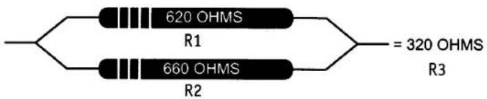
When using the Directed Resistor Interface Pack, some circuits may require a different resistance value than the resistors supplied. If necessary, different resistance values may be obtained by combining the resistors in a parallel or series connection, both of which will provide different values.
For example, if the 620 OHM resistor and the 660 OHM resistor are wired in parallel, the value is 320 OHMS. The same resistors wired in a series configuration will produce a value of 1280 OHMS. This allows greater flexibility with more values to use while interfacing with the multiplexed systems of today's vehicles.
Series Connection
In a series connection, the end value is the sum of Resistor 1 (R1) and Resistor 2 (R2). I.e., R1 + R2 = R3.

Parallel Connection
In a parallel connection, the end value is determined by Resistor 1 (R1) multiplied by Resistor 2 (R2). That total is then divided by the sum of R1 and R2. I.e., (R1 × R2)(R1 + R2) = R3
Please refer to DirectFax Doc. 1041.
Resistor Values
| Resistor Value (OHMS) | Colors |
| 249 | Red, Yellow, White, Black, Brown |
| 330 | Orange, Orange, Brown, Gold |
| 365 | Orange, Blue, Green, Black, Brown |
| 390 | Orange, White, Brown, Gold |
| 430 | Yellow, Orange, Brown, Gold |
| 470 | Yellow, Violet, Brown, Gold |
| 487 | Yellow, Gray, Violet, Black, Brown |
| 560 | Green, Blue, Brown, Gold |
| 620 | Blue, Red, Black, Black, Brown |
| 665 | Blue, Blue, Green, Black, Brown |
| 750 | Violet, Green, Brown, Gold |
| 820 | Gray, Red, Brown, Gold |
| 867 | Gray, Blue, Violet, Black, Brown |
| 931 | White, Orange, Brown, Black, Brown |
| 1000 | Brown, Black, Red, Gold |
| 1200 | Brown, Red, Red, Gold |
| 1500 | Brown, Green, Red, Gold |
| 1870 | Brown, Gray, Violet, Brown, Brown |
| 2000 | Red, Black, Red, Gold |
| 2700 | Red, Violet, Black, Brown, Brown |
| 3000 | Orange, Black, Red, Gold |
| 4020 | Yellow, Black, Red, Brown, Brown |
| 4700 | Yellow, Violet, Red, Gold |
| 5360 | Green, Orange, Blue, Brown, Brown |
| 7150 | Violet, Brown, Green, Brown, Brown |
| 7500 | Violet, Green, Red, Gold |
| 9100 | White, Brown, Red, Gold |
Vehicle Applications
| Vehicle | Polarity | Lock | Unlock | Arm | Disarm |
| '96 Caravan, Voyager, and Town & Country | (-) | 1500 ohm | 250 ohm | 4,020 ohm | 665 ohm |
| '95 and up Stratus, Cirrus, and Breeze | (+) | 1,500 ohm | |||
| '89 and up Probe | (+) | 4,700 ohm | |||
| '95 and up Millenia | (-) | 1,000 ohm | |||
| '99 Alero and Grand Am | (-) | 1,500 ohm | |||
| '98 and up LHS, 300M, Concorde, and Intrepid | (+) | 2,700 ohm | 620 ohm |


Brand : Viper
Model : XpressKit 451M
Category : Remote control