
XpressKit 507M Tilt Sensor - Remote control Viper - Free user manual and instructions
Find the device manual for free XpressKit 507M Tilt Sensor Viper in PDF.


| Brand | Viper |
| Model | XpressKit 507M |
| Product Type | Remote Control with Tilt Sensor |
| Dimensions (approx.) | 6.0 x 3.0 x 1.2 cm |
| Weight (approx.) | 50 g (including battery) |
| Power Source | 1 x CR2032 3V Lithium Coin Battery |
| Operating Frequency | 433.92 MHz (typical for Viper remotes) |
| Range (approx.) | Up to 100 meters in open area |
| Primary Functions | Arm/Disarm, Panic, Trunk Release, Tilt Sensor Alert |
| Tilt Sensor Sensitivity | Adjustable (4 levels) |
| LED Indicator | Red/Green for status feedback |
| Case Material | ABS Plastic |
| Water Resistance | Not water resistant; keep dry |
| Battery Life | Approximately 1 year with normal use |
| Low Battery Warning | LED flashes rapidly |
| Compatibility | Viper 507M compatible control modules |
| Pairing Method | Learn mode or onboard programming |
| Maintenance | Clean with soft, dry cloth. Do not use solvents. |
| Storage | Store in a cool, dry place away from direct sunlight |
| Safety | Keep out of reach of children. Contains small parts and battery. |
| Spare Parts Available | Replacement batteries (CR2032), silicone cases |
| Certifications | FCC, CE, RoHS compliant |
Frequently Asked Questions - XpressKit 507M Tilt Sensor Viper
User questions about XpressKit 507M Tilt Sensor Viper
0 question about this device. Answer the ones you know or ask your own.
Ask a new question about this device
Download the instructions for your Remote control in PDF format for free! Find your manual XpressKit 507M Tilt Sensor - Viper and take your electronic device back in hand. On this page are published all the documents necessary for the use of your device. XpressKit 507M Tilt Sensor by Viper.
USER MANUAL XpressKit 507M Tilt Sensor Viper
The 507M Tilt Sensor is used to compliment the level of security provided by the existing sensors found on most alarm systems. The tilt sensor detects when the vehicle is being raised in an attempt to remove the wheels or tow the vehicle. The 507M is capable of independently referencing the vehicle's initial angles of inclination each time the vehicle is parked, ensuring the most accurate tilt sensing possible.
Mounting the Control Module
The sensor control module must be mounted at an angle no greater than 45 degrees, with respect to the horizontal plane of the vehicle, and it must be mounted with the case top facing upward. We recommend mounting the control module to the floor of the vehicle. To mount the control module, fasten the unit with the provided double stick foam tape or screw to secure it in place.
Wiring Instructions
To wire the 507M, simply plug the 3-pin harness into the control module and connect the wires as shown below:
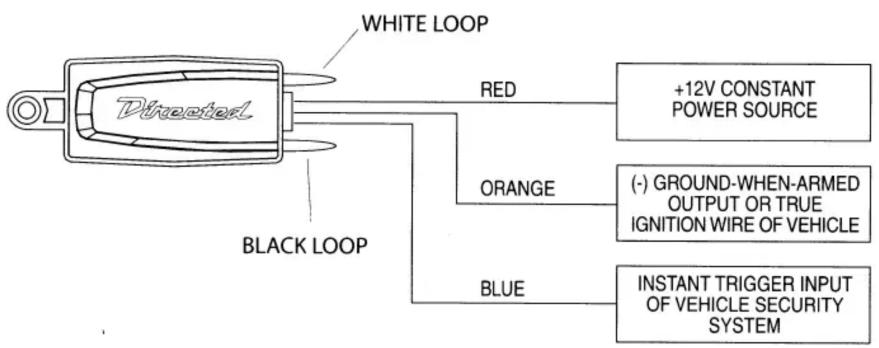
RED (+)12V Constant: Connect this wire to a (+)12V constant power source.
ORANGE (-) Turn-on Input: Connect this wire to the (-) ground-when-armed output of the vehicle security system. If the security system does not provide a (-) ground-when-armed output. An alternative solution is to connect this wire to the true ignition wire of the vehicle (this wire must rest at ground when the ignition key is in the OFF position).
IMPORTANT! In order for the 507M to learn the inclination angle each time the vehicle is parked, the ORANGE wire must be connected to a security system ground-when-armed output or to an acceptable switched ignition ground reference wire.
BLUE (-) Trigger Output: Connect this wire to the instant trigger input of the vehicle security system.
Programming the Sensor
The unit has 2 wire loops (one WHITE and the other BLACK) for setting both the tilt threshold and the arming delay. The 2 wire loops are located on the side of the sensor next to the harness plug.
TILT SENSITIVITY THRESHOLD
The BLACK loop controls the tilt sensitivity threshold that detects when the vehicle is being lifted. A 1-degree threshold is the default setting for extreme sensitivity. If the BLACK loop is cut, then a 3-degree threshold is selected for normal sensitivity.
ARMING DELAY
The WHITE loop sets the amount of time the sensor waits before it will become active. A 10-second delay is the default setting. If the WHITE loop is cut, then a 2-minute delay is selected before becoming active.


Brand : Viper
Model : XpressKit 507M Tilt Sensor
Category : Remote control