
4816V - Remote control Viper - Free user manual and instructions
Find the device manual for free 4816V Viper in PDF.


| Product Type | Remote control |
| Brand | Viper |
| Model | 4816V |
| Dimensions (approx.) | 15 x 5 x 2 cm |
| Weight (approx.) | 100 g |
| Power Source | 2 x AAA batteries (not included) |
| Operating Range | Up to 10 meters |
| Frequency | 433 MHz |
| Functions | Power on/off, volume control, channel selection, numeric keypad, menu navigation |
| Compatibility | Viper 4816V compatible devices |
| Indicators | LED indicator for transmission |
| Material | Plastic |
| Color | Black |
| Cleaning | Wipe with a soft, dry cloth. Do not use solvents. |
| Battery Replacement | Open battery compartment, insert AAA batteries with correct polarity. |
| Safety | Do not expose to moisture or heat. Keep away from children. |
| Spare Parts | Batteries; replacement remote available from Viper. |
| Repair | No user-serviceable parts. Contact Viper support for repair. |
| Storage | Store in a cool, dry place. |
Frequently Asked Questions - 4816V Viper
User questions about 4816V Viper
0 question about this device. Answer the ones you know or ask your own.
Ask a new question about this device
Download the instructions for your Remote control in PDF format for free! Find your manual 4816V - Viper and take your electronic device back in hand. On this page are published all the documents necessary for the use of your device. 4816V by Viper.
USER MANUAL 4816V Viper
natural_image
Illustration of a large snake head with its open mouth, set against a yellow background (no text or symbols)OWNER'S GUIDE
M O D E L
4811V
4816V
Congratulations
Congratulations on the purchase of your remote start system. This system has been designed to provide years of trouble-free operation. By carefully reading this owner's guide prior to using your system, you will maximize the use of this system and its features.
For more information please visit us online (see back cover for URL). For any additional questions please contact your authorized Directed dealer or contact Directed at 1-800-753-0600 (U.S. only) or 1-800-361-7271 (Canada only). Additional support is also available at: http://support.directed.com
What you get
• One 2-way, 1-button remote control
• One 1-way, 1-button remote control
- Owners Guide
Replacement Remote controls
Please see your authorized dealer or visit us at www.directedstore.com to order additional remote controls. Remote control part numbers are found on the back of the device.
Important Information
Government Regulations and Safety Information

Read the "Government Regulations" and "Warning!
Safety First" sections of this manual prior to operating this system.
Warning! Failure to heed this information can result in death, personal injury or property damage and may also result in the illegal use of the system beyond its intended purpose.
This product is designed for fuel-injected, automatic transmission vehicles only. Installing it in a standard transmission vehicle is dangerous and is contrary to its intended use. If your vehicle is equipped with a manual transmission cease use of this product and immediately return the vehicle to an authorized Directed dealer.
Your warranty
Your system comes with a warranty. The warranty terms are detailed at the end of this guide. Make sure that you receive the proof of purchase from your dealer, indicating the product was installed by an authorized Directed dealer.
Contents
Congratulations ....i
What you get ....i
Replacement Remote controls ....i
Important Information ....ii
Government Regulations and Safety Information ......ii
Your warranty....ii
Using Your System 2
Commands At a Glance 2
Start Engine 2
Unlock Doors 2
Stop Engine 2
Car Finder 3
Using Remote Start ....3
Key Takeover....4
Safety Features 4
Pit Stop and Turbo Timer Modes 5
Manual Transmission Vehicles 6
Low Runtime and Remote Start Shutdown Alerts 7
Optional Rear Defogger 7
Starter Anti-Grind Circuitry 7
Disabling the Remote Start System 7
Remote Start Faults 8
Rapid Resume Logic 8
Remote Pairing 9
Programming Options 10
Battery Information 11
Battery Disposal 12
Glossary of Terms....12
Government Regulations 14
Warning! Safety First 15
Installation 15
Remote Start Capable 15
Manual Transmission Vehicles 15
Interference....17
Upgrades 17
Water/Heat Resistance 17
Limited lifetime consumer warranty 18
Commands At a Glance
| System State | Press/Release | Press/Hold for 3 sec. |
| ENGINE OFF START ENGINE CAR FINDER | ||
| ENGINE ON UNLOCK DOORS STOP ENGINE | ||
Note: If a feature cannot be activated when performing a command with the 2-way remote control or if the system is out of range, a fault tone plays as an alert.
Start Engine
When the engine is OFF, press and release the remote control button to start the engine.
See "Using Remote Start" on page 3 for more feature details.
Unlock Doors
When the engine is ON with remote start, press and release the remote control button. The doors unlock, the parking lights flash, the horn sounds (if connected) as confirmation. The 2-way remote control emits tones.
Note: Horn honk may be an optional feature that requires additional parts and labor.
Stop Engine
When the engine is ON with remote start, press and hold the remote control button for three seconds. The engine stops running and the parking lights turn off. The 2-way remote control emits tones.
Car Finder
When the engine is OFF, press and hold the remote control button for three seconds. The horn sounds once (if connected) and the parking lights flash multiple times. The 2-way remote control emits a single tone.
Using Remote Start
This feature allows you to remotely start and run your vehicle for a programmable period of time. This makes it possible to warm up the engine, and adjust the interior temperature of the vehicle with the climate control system. If interior heating or cooling is desired, the climate controls must be preset, and the fan blower must be set to the desired level prior to remote starting the vehicle.
Important! (1) Never remotely start the vehicle with the vehicle in gear, and (2) Never remotely start the vehicle with the key in the ignition.
Starting the Engine:
- Make sure the parking brake is set. Press and release the remote control button once* (or the amount of times the system has been programmed to activate the remote start).
- The engine will START and the parking lights will turn on. The 2-way remote will also emit tones.
The parking lights stay on as visual confirmation while the engine is ON. The default runtime is 12 minutes and can be shortened or extended by the installer. If a remote start configuration issue prevents the engine from starting, the parking lights flash a remote start fault report to identify the fault. See "Remote Start Faults" on page 8.
* The factory setting is one press but this can also be programmed for two presses (See your authorized Directed installer for the amount of presses programmed).
Record the number of presses to activate remote start here:
Key Takeover
When you are ready to drive the vehicle:
- Unlock the doors.
- Enter the vehicle. Do not step on the foot brake.
- Insert the key into the ignition and turn it to the run (not start) position.
- Step on the foot brake. The remote start is disabled and the parking lights turn off.
- Disengage the parking brake and begin driving.
Note
If your vehicle uses a Smart Key or PTS (Push-To-Start) system, please refer to the vehicle specific instructions included with the owner's guide of the interface module or consult your authorized dealer.
Safety Features
The following safety features will disable the remote start when activated or not allow the engine to start if not properly set before starting.
- Foot Brake is depressed
- Hood is open
- Remote Start shutoff switch is OFF
- The pre-programmed run time (12, 24 or 60 minutes) has elapsed
- Remote Start activation procedure is repeated
- Parking brake is disengaged
• Engine over-rev protection (Tachometer mode only)
Pit Stop and Turbo Timer Modes
This remote start can keep the engine running during short trips away from the vehicle or to cool down turbo timers.
Enabling Pit Stop mode:
- Park in a well ventilated area.
- With the engine running engage the parking brake and release the foot brake.
- Press and release the remote control button once (or the amount of times the system has been programmed to activate the remote start). The parking lights turn on as confirmation.
- Turn off the ignition and remove the key, the engine continues running.
- Exit the vehicle, the engine runs for the programmed runtime.
Enabling Turbo Timer mode * :
Begin by following the "Enabling Pit Stop mode" procedure. However, in step 3, instead of pressing the remote control button, press and release the dash mounted activation button* once (or the amount of times the system has been programmed to activate the remote start). The engine continues running for the shorter Turbo Mode runtime. Continue and complete the procedure steps.
* Turbo Timer mode must be turned on and an optional activation button also installed by an authorized dealer.
Note: For Manual Transmission vehicles see "Manual Transmission Vehicles" on page 6.
| Note | If your vehicle uses a Smart Key or PTS (Push-To-Start) system, please refer to the vehicle specific instructions included with the owner's guide of the interface module or consult your authorized dealer. |
Manual Transmission Vehicles
Manual Transmission Mode (MTS), Pit Stop mode, Turbo Timer Mode
Enabling MTS mode
- Park in a well ventilated area with all the doors closed.
- With the engine running, press the foot brake and set the parking brake.
- Release the foot brake.
- Press and release the remote control button, the parking lights flash quickly five times as confirmation.
- Turn off the ignition and remove the key, the engine continues running.
- Exit the vehicle.
- When the doors are closed, the engine stops running, MTS mode is enabled.
Note: If enabling MTS mode has failed, the parking lights flash slowly five times, return to step 1 and repeat procedure.
Enabling Pit Stop mode:
Follow the previous Enabling MTS mode procedure, however, open a door prior to step 4. The engine continues running for the programmed runtime after the doors are closed.
Enabling Turbo Timer mode\*:
Follow the previous Enabling MTS mode procedure, however, open a
door prior to Step 4. Then, instead of pressing the remote control button, press and release the optional dash mounted activation button*. The engine continues running for the shorter Turbo Mode runtime after the doors are closed.
* Turbo Timer mode must be turned on and an optional activation button also installed by an authorized dealer.
Low Runtime and Remote Start Shutdown Alerts
During remote start, the system sill send a low runtime alert to the 2-way remote when the remote start reaches the three minute and one minute runtime remaining point. When the remote start shuts down, the 2-way remote will also play a descending tone to indicate that the remote start has shutoff.
Optional Rear Defogger
If connected, the Defogger circuit automatically activates ten seconds after remote starting the vehicle if the temperature is below 55^ F ( 12.8^ C).
Starter Anti-Grind Circuitry
This system includes an anti-grind circuit (optional relay is required) that can prevent damage to the starter motor if the key is turned to the start position while the engine is ON.
Note: Anti-grind circuitry only works when the remote start system is operating the motor and the optional relay is installed.
Disabling the Remote Start System
When the Remote Start shutoff switch is set to the OFF position, remote engine starting is defeated. DO this when the vehicle is being serviced
or driven by someone unfamiliar with remote start system operations.
Location Of Remote Start shutoff switch: ____
Remote Start Faults
For user safety, the system must be properly configured or remote start will not activate. A Remote Start Fault may be caused by any of several configuration issues. Refer to the table below for the command type and parking light flashes that will identify the configuration issue and solution.
| Flashes * Possible Fault Solution | ||
| 5 Brake on Release foot brake | ||
| 6 Hood open Close hood | ||
| 7 After performing Remote Start command - MTS not enabled | Enable MTS mode | |
| 8 Toggle Switch off Turn switch on | ||
Rapid Resume Logic
This Directed system stores its current state to non-volatile memory. If power is lost and then reconnected the system recalls the stored state from memory. This means if the unit is in Locked Mode and the battery is disconnected for any reason, such as when servicing the vehicle, when the battery is reconnected the unit maintains Locked Mode. This applies to all states of the system.
Remote Pairing
Your system comes with two remote controls that are already paired to the system. An additional two remote controls can be stored in the system's memory (for a maximum of four). However, additional or replacement remote controls need to paired to the system first before use. Use the following procedure to pair an additional or replacement remote control to the system.
To pair a new remote control to the system:
- Turn the ignition to the ON position.
- Within ten seconds, press/release once and then press and hold the control button on the system's control center. The status LED begins flashing in a sequence of single flashes and the horn sounds (if connected) to confirm the system is ready for pairing. Release the control center button.
- Press and release the button on the remote control twice and then, press and hold on the third press. The transmit LED comes on solid, continue holding the button until the transmit LED changes its pattern. Release the button and the transmit LED begins flashing as an indication that the remote control has entered pairing mode.
- Press and release the button on the remote control.
- The horn (if connected) sounds as a confirmation the system has paired with the remote control and the 2-way remote control plays tones confirming that it has paired with the system and will automatically exit pairing mode. The 1-way remote does not emit any confirmation tones. The remote will exit programming after 30 seconds or to manually exit programming, press and hold the button on the remote. The remote emits a tone confirming exit.
- Turn the ignition off or wait 60 seconds for the system to exit the pairing mode, the horn will sound as confirmation.
The learn routine Exits if any of the following occurs:
• The ignition is turned off.
• There is no activity for 60 seconds.
- The control button is pressed too many times.
Programming Options
Programming options control your system's normal operational setup. Most options do not require additional parts, but some may require installation labor.
The following is a list of the programmable options, with the factory settings in bold.
- 12, 24, or 60 minute run time. Your system can be programmed to allow the vehicle to run for 12, 24, or 60 minutes when remote started. Can be set up to minute increments by your installer.
- Parking lights flashing or constant. Your system can be programmed to flash or turn on the parking lights constantly during the entire remote start operation.
- Ignition switch controlled door locking on or OFF. With this feature on, the doors will lock three seconds after the ignition key is turned on, and unlock when the key is turned off.
Important: The door lock option must be installed for this feature to work.
Battery Information
The 1-way remote controls are powered by a single coin cell battery (CR-2016), and the 2-way remote controls are powered by two coin cell batteries (CR-2016) that can be purchased at most retailers. Operating range diminishes as battery charge depletes.
Low Battery Alert
When unlocking the vehicle using a remote control with a low battery charge, the system provides a notification by emitting a third horn honk output (if connected). If confirmation chirps are programmed off, the system still emits one horn honk when unlocking. After performing a command with the remote control, several beeps play to indicate the battery/batteries need replacing. Once the alerts begin, the remote control will remain operational for several days but the battery/batteries should be replaced at the earliest opportunity or failure to control the system may occur.
Battery Replacement
- Unscrew the hardware on unit rear and remove from housing.
- Use a small flat blade screwdriver and insert it into the slot located along the bottom of the remote, near the key ring. Carefully pry open the case.
- Gently slide out the used battery/batteries to remove it from the holding clip. Orient the new battery for the correct polarity and insert into holding clip.
- Realign the case parts and snap together by pressing firmly and evenly on the front and back. Reinstall screw.
Battery Disposal

Directed cares about the environment. If you need to dispose of the battery, please do so in accordance with your municipal requirements for battery disposal.
Glossary of Terms
| Document Terminology | |
| Control Module | The “brain” of your system. Usually hidden underneath the dash area of the vehicle. It houses the microprocessor which monitors your vehicle and controls all of the system's functions. |
| Remote Control | A hand-held, remote control which operates the various functions of your system. |
| Status LED | Transmit LED (Light Emitting Diode): A light used to indicate the status of your system. It turns on when a button is pressed or communication is active. |
| Control Center | Mounted high in the vehicle usually on the windshield in a location close to the rear view mirror. Consists of a antenna/receiver for communicating between the control module and remote controls and a control button with status LED for programming system features. |
| Remote Start shutoff switch | Normally located near the control module or mounted around the dashboard, this Remote Start shutoff switch is used to disable the remote start feature. |
This product is covered by one or more of the following United States patents:
Vehicle Security Patents
5,467,070; 5,532,670; 5,534,845; 5,563,576; 5,646,591; 5,650,774; 5,673,017; 5,712,638; 5,872,519; 5,914,667; 5,952,933; 5,945,936; 5,990,786; 6,028,505; 6,452,484
Remote Start
5,349,931; 5,872,519; 5,914,667; 5,952,933; 5,945,936; 5,990,786; 6,028,372; 6,467,448; 6,561,151; 7,191,053; 7,483,783
Other patents pending
Government Regulations
This device complies with Part 15 of FCC rules. Operation is subject to the following two conditions: (1) This device may not cause harmful interference, and (2) This device must accept any interference received, including interference that may cause undesirable operation.
This equipment has been tested and found to comply with the limits for a class B digital device, pursuant to Part 15 of the FCC Rules. These limits are designed to provide reasonable protection against harmful interference in a residential installation. This equipment generates and can radiate radio frequency energy and, if not installed and used in accordance with the instruction manual, may cause harmful interference to radio communications. However, there is no guarantee that interference will not occur in a particular installation. If this equipment does cause harmful interference to radio or television, which can be determined by turning the equipment OFF and ON, the user is encouraged to try to correct the interference by one or more of the following measures:
- Reorient or relocate the receiving antenna.
- Increase the separation between the equipment and receiver.
- Connect the equipment into an outlet on a circuit different from that to which the receiver is connected.
- Consult the dealer or an experienced radio / TV technician for help.
This device complies with the Industry Canada Radio Standards Specification RSS 210. Its use is authorized only on a no-interference, no-protection basis; in other words, this device must not be used if it is determined that it causes harmful interference to services authorized by IC. In addition, the user of this device must accept any radio interference that may be received, even if this interference could affect the operation of the device.
Warning: Changes or modifications not expressly approved by the party responsible for compliance could void the user's authority to operate this device.
Warning! Safety First

Please read the safety warnings below before proceeding. Improper use of the product may be dangerous or illegal.
Installation
Due to the complexity of this system, installation of this product must only be performed by an authorized Directed dealer. If you have any questions, ask your retailer or contact Directed directly at 1-800-753-0600.
Remote Start Capable
When properly installed, this system can start the vehicle via a command signal from the remote control transmitter. Therefore, never operate the system in an enclosed area or partially enclosed area without ventilation (such as a garage). When parking in an enclosed or partially enclosed area or when having the vehicle serviced, the remote start system must be disabled using the installed menu wheel. It is the user's sole responsibility to properly handle and keep out of reach from children all remote control transmitters to assure that the system does not unintentionally remote start the vehicle. THE USER MUST INSTALL A CARBON MONOXIDE DETECTOR IN OR ABOUT THE LIVING AREA ADJACENT TO THE VEHICLE. ALL DOORS LEADING FROM ADJACENT LIVING AREAS TO THE ENCLOSED OR PARTIALLY ENCLOSED VEHICLE STORAGE AREA MUST AT ALL TIMES REMAIN CLOSED. These precautions are the sole responsibility of the user.
Manual Transmission Vehicles
Remote starters on manual transmission vehicles operate differently than those with automatic transmission because you must leave your car in neutral. You must read this Owner's Guide to familiarize yourself with the proper procedures regarding manual transmission remote starters. If you have any questions, ask your authorized Directed dealer or contact Directed at 1-800-753-0600.
Before remote starting a manual transmission vehicle, be sure to:
- Leave the vehicle in neutral and be sure no one is standing in front or behind the vehicle.
- Only remote start on a flat surface
• Have the parking brake fully engaged
WARNING! It is the responsibility of the owner to ensure the parking/emergency brake properly functions. Failure to do so can result in personal injury or property damage. We recommend the owner have the parking / emergency brake system inspected and adjusted by a qualified automotive shop biannually.
Use of this product in a manner contrary to its intended mode of operation may result in property damage, personal injury, or death. (1) Never remotely start the vehicle with the vehicle in gear, and (2) Never remotely start the vehicle with the keys in the ignition. The user must also have the neutral safety feature of the vehicle periodically checked, wherein the vehicle must not remotely start while the car is in gear. This testing should be performed by an authorized Directed dealer in accordance with the Safety Check outlined in the product installation guide. If the vehicle starts in gear, cease remote start operation immediately and consult with the authorized Directed dealer to fix the problem.
After the remote start module has been installed, contact your authorized dealer to have him or her test the remote start module by performing the Safety Check outlined in the product installation guide. If the vehicle starts when performing the Neutral Safety Shutdown Circuit test, the remote start unit has not been properly installed. The remote start module must be removed or the installer must properly reinstall the remote start system so that the vehicle does not start in gear. All installations must be performed by an authorized Directed dealer.
OPERATION OF THE REMOTE START MODULE IF THE VEHICLE STARTS IN GEAR IS CONTRARY TO ITS INTENDED MODE OF OPERATION. OPERAT-
ING THE REMOTE START SYSTEM UNDER THESE CONDITIONS MAY RESULT IN PROPERTY DAMAGE OR PERSONAL INJURY. YOU MUST IMMEDIATELY CEASE THE USE OF THE UNIT AND SEEK THE ASSISTANCE OF AN AUTHORIZED Directed DEALER TO REPAIR OR DISCONNECT THE INSTALLED REMOTE START MODULE. DIRECTED WILL NOT BE HELD RESPONSIBLE OR PAY FOR INSTALLATION OR REINSTALLATION COSTS.
This product is designed for fuel injected vehicles only. Use of this product in a standard transmission vehicle must be in strict accordance with this guide.
This product should not be installed in any convertible vehicles, soft or hard top with a manual transmission. Installation in such vehicles may pose certain risk.
Interference
All radio devices are subject to interference which could affect proper performance.
Upgrades
Any upgrades to this product must be performed by an authorized Directed dealer. Do not attempt to perform any unauthorized modifications to this product.
Water/Heat Resistance
This product is not designed to be water and/or heat-resistant. Please take care to keep this product dry and away from heat sources. Any damage from water or heat will void the warranty.
Limited lifetime consumer warranty
Directed Electronics. ("Directed") promises to the original purchaser to repair or replace (at Directed's election) with a comparable reconditioned model any Directed unit (hereafter the "unit"), excluding without limitation the siren, the remote transmitters, the associated sensors and accessories, which proves to be defective in workmanship or material under reasonable use during the lifetime of the vehicle provided the following conditions are met: the unit was purchased from an authorized Directed dealer, the unit was professionally installed and serviced by an authorized Directed dealer; the unit will be professionally reinstalled in the vehicle in which it was originally installed by an authorized Directed dealer; and the unit is returned to Directed, shipping prepaid with a legible copy of the bill of sale or other dated proof of purchase bearing the following information: consumer's name, telephone number and address; the authorized dealers name, telephone number and address; complete product description, including accessories; the year, make and model of the vehicle; vehicle license number and vehicle identification number. All components other than the unit, including without limitation the siren, the remote transmitters and the associated sensors and accessories, carry a one-year warranty from the date of purchase of the same. ALL PRODUCTS RECEIVED BY DIRECTED FOR WARRANTY REPAIR WITHOUT PROOF OF PURCHASE FROM AN AUTHORIZED DEALER WILL BE DENIED. This warranty is non-transferable and is automatically void if: the unit's date code or serial number is defaced, missing or altered; the unit has been modified or used in a manner contrary to its intended purpose; the unit has been damaged by accident, unreasonable use, neglect, improper service, installation or other causes not arising out of defects in materials or construction. The warranty does not cover damage to the unit caused by installation or removal of the unit. Directed, in its sole discretion, will determine what constitutes excessive damage and may refuse the return of any unit with excessive damage.
TO THE MAXIMUM EXTENT ALLOWED BY LAW, ALL WARRANTIES, INCLUDING BUT NOT LIMITED TO EXPRESS WARRANTY, IMPLIED WARRANTY, WARRANTY OF MERCHANTABILITY, FITNESS FOR PARTICULAR PURPOSE AND WARRANTY OF NON-INFRINGEMENT OF INTELLECTUAL PROPERTY, ARE EXPRESSLY EXCLUDED; AND DIRECTED NEITHER ASSUMES NOR AUTHORIZES ANY PERSON OR ENTITY TO ASSUME FOR IT ANY DUTY, OBLIGATION OR LIABILITY IN CONNECTION WITH ITS PRODUCTS. DIRECTED DISCLAIMS AND HAS ABSOLUTELY NO LIABILITY FOR ANY AND ALL ACTS OF THIRD PARTIES INCLUDING ITS AUTHORIZED DEALERS OR INSTALLERS. DIRECTED SECURITY SYSTEMS, INCLUDING THIS UNIT, ARE DETERRENTS AGAINST POSSIBLE THEFT. DIRECTED IS NOT OFFERING A GUARANTEE OR INSURANCE AGAINST VANDALISM, DAMAGE OR THEFT OF THE AUTOMOBILE, ITS PARTS OR CONTENTS; AND HEREBY EXPRESSLY DISCLAIMS ANY LIABILITY WHATSOEVER, INCLUDING WITHOUT LIMITATION, LIABILITY FOR THEFT, DAMAGE AND/OR VANDALISM. THIS WARRANTY DOES NOT COVER LABOR COSTS FOR MAINTENANCE, REMOVAL OR
REINSTALLATION OF THE UNIT OR ANY CONSEQUENTIAL DAMAGES OF ANY KIND. IN THE EVENT OF A CLAIM OR A DISPUTE INVOLVING DIRECTED OR ITS SUBSIDIARY, THE VENUE SHALL BE SAN DIEGO COUNTY IN THE STATE OF CALIFORNIA. CALIFORNIA STATE LAWS AND APPLICABLE FEDERAL LAWS SHALL APPLY AND GOVERN THE DISPUTE. THE MAXIMUM RECOVERY UNDER ANY CLAIM AGAINST DIRECTED SHALL BE STRICTLY LIMITED TO THE AUTHORIZED DIRECTED DEALER'S PURCHASE PRICE OF THE UNIT. DIRECTED SHALL NOT BE RESPONSIBLE FOR ANY DAMAGES WHATSOEVER, INCLUDING BUT NOT LIMITED TO, ANY CONSEQUENTIAL DAMAGES, INCIDENTAL DAMAGES, DAMAGE TO VEHICLE, DAMAGES FOR THE LOSS OF TIME, LOSS OF EARNINGS, COMMERCIAL LOSS, LOSS OF ECONOMIC OPPORTUNITY AND THE LIKE. NOTWITHSTANDING THE ABOVE, THE MANUFACTURER DOES OFFER A LIMITED WARRANTY TO REPLACE OR REPAIR THE CONTROL MODULE SUBJECT TO THE CONDITIONS AS DESCRIBED HEREIN. THIS WARRANTY IS VOID IF THE UNIT HAS NOT BEEN PURCHASED FROM DIRECTED, OR AN AUTHORIZED DIRECTED DEALER, OR IF THE UNIT HAS BEEN DAMAGED BY ACCIDENT, UNREASONABLE USE, NEGLIGENCE, ACTS OF GOD, NEGLECT, IMPROPER SERVICE, OR OTHER CAUSES NOT ARISING OUT OF DEFECT IN MATERIALS OR CONSTRUCTION.
Some states do not allow limitations on how long an implied warranty will last or the exclusion or limitation of incidental or consequential damages. This warranty gives you specific legal rights and you may also have other rights that vary from State to State.
This warranty is only valid for sale of product(s) within the United States of America and in Canada. Product(s) sold outside of the United States of America or Canada are sold "AS-IS" and shall have NO WARRANTY, express or implied.
For further details relating to warranty information of Directed products, please visit the support section of Directed's website at: www.directed.com
This product may be covered by a Guaranteed Protection Plan ("GPP"). See your authorized Directed dealer for details of the plan or call Directed Customer Service at 1-800-876-0800.
920-10011-01 2011-06
DIRECTED®
The company behind Viper® Auto Security Systems is Directed.
Since its inception, Directed has had one purpose, to provide consumers with the finest vehicle security and accessories available. The recipient of nearly 100 patents and Innovations Awards in the field of advanced electronic technology.
Quality Directed products are sold and serviced throughout North America and around the world.
Call (800) 876-0800 for more information about our products and services.
© 2015 Directed. All rights reserved.
G4816V ML 2015-07
Vista, CA 92081
www.viper.com
Directed is committed to delivering world class quality products and services that excite and delight our customers.
Quick Reference Install Guide Model 4816
1-Button, 1 & 2-Way Systems
Important: The Conno Center has been replaced, other remote controls may be replaced with the system. See Remote Paring for details.
Wiring Connections
Main Harness, 6-pin connector
| 1 | RED | L:12VDC. CONSTANT INPUT |
| 2 | BLACK | L:CHASSICS GROUP |
| 3 | BROWN | L:200mA HORN HOOK OUTPUT |
| 4 | WHITE/BROWN | LIGHT FLASH ISOLATION WIRE - PLN 87s of light flash stay |
| 5 | WHITE | LIGHT FLASH OUTPUT - FIR 90 or light flash stay |
| 6 | ORANGE | L:500mA GROUND WHEN ARVED OUTPUT |
Door Lock, 3-pin connector
| 1 | BLUE | ( ) 500mA UNLOCK OUTPUT |
| 2 | ENPTY | NOT USED |
| 3 | GREEN | ( ) 500mA LOCK OUTPUT |
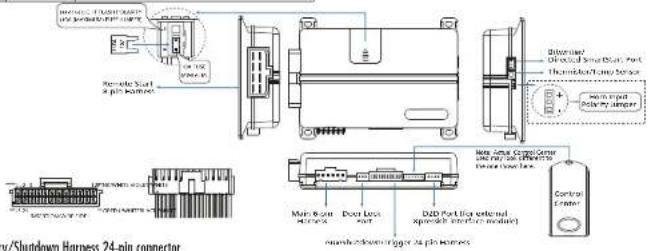
Auxiliary/Shutdown Harness 24-pin connector
| 1 | PICK/WHITE | ( ) 200VA EQTRON 2/Rack OUTPUT |
| 2 | BLUE/WHITE | ( ) 200VA END STATUS/YEAR DEFROGER OUTPUT |
| 3 | RED/WHITE* | ( ) 200VA TRUNK RELEASE OUTPUT |
| 4 | BLACK/YELLOW | ( ) 200VA DOME LIGHT OUTPUT |
| 5 | CARE BLUE | ( ) 200VA STATUS OUTPUT |
| 6 | WHITE/BLACK * | ( ) 200VA AUX 3 OUTPUT |
| 7 | WHITE/VOLET * | ( ) 200VA AUX 4 OUTPUT |
| 8 | ORANGE/BLACK * | ( ) 200VA AUX 4 OUTPUT |
| 9 | GRAY | ( ) GOOD FCN OUTPUT (NO OR NO) |
| 10 | BLUE** | FACTORY HORN OUTPUT (NO DUNION TO SET POURF) |
| 11 | WHIP/WHIP*** | ( ) ACTIVATION OUTPUT |
| 12 | WHITE/WHITE**** | ( ) CHISPONE OUTPUT |
| 13 | BLACK/WHITE **** | ( ) ZAFFORD ONION OUTPUT |
| 14 | GREEN/BLACK | ( ) ZENKA FACTORY ALARM DISCUIT OUTPUT |
| 15 | GREEN**** | ( ) ZONE OUTPUT |
| 16 | EXPPLY | ____ |
© 2014 Survey of Environmental
| Notice to InstallerA Report Start Salary Check must be performed before returning the vehicle to the owner. This Salary Checklist document (TR101) can be found online by going to www.structured.com and can also be found in the U- online installation guide (IM3015). |
Guide Translations
[or a Spanish Ita Tradicenter a Español] or French [Traduction on fraternal version of the Installation Guide, please download 1 from www.dteuedits.com under "Sapirocas"
Remote Start, B-pin connector
| 1 | RED/BLACK | (4) 220K CONSTANT INPUT for AIC and starter wheels |
| 2 | PUM/BLACK * | (5) FLEX RELAY INPUT (AIA key side of required) of FLEX RELAY |
| 3 | PUM/WHITE | (6) ENITION 2 / FLEX RELAY OUTPUT |
| 4 | RED | (7) 220K CONSTANT INPUT for ignition 1 relay |
| 5 | VOLT | (8) STARTER OUTPUT |
| 6 | DRANGE | (9) ACCESSORY OUTPUT |
| 7 | R/PWMALL | (10) 276K LUXWABLE INPUT for ignition 2 and fan relays |
| 8 | PWR | (11) CONTROL 1 INPUT/OUTPUT |
* This wire is only used in applications that require a specific circuit at the ignition switch to be injured during the remote circuit sequence.
| 17 | POCK | (+) 200mA SWITCH: OUTPUT |
| 18 | COLET***** | (+) DOOR INPUT |
| 19 | COLET/BLACK | (+) 200mA AUX 2 OUTPUT |
| 20 | BROWN | (+) BROWN SHUTDOWN INPUT |
| 21 | COLET/YELLOW | (+) 200mA STARTER OUTPUT |
| 22 | RAW/BLACK | (+) BROWN OUT TO START OUTPUT |
| 23 | DRANGE | (+) 200mA ACCESSORY OUTPUT |
| 24 | GREEN/WHITE | (+) 200mA FACTORY ALARM AIR OUTPUT |
- Use channels with the 1 button remote car only be accessed with screen, linking to clock or remote car with the control. Sera-Great module.
** This option Input can be converted to the home credit or in vehicles with factory alarm. When this wire recels input for a minimum of 0.5 seconds, the system reports an alarm bigger on the Heavy class. This line is not applied to the heavy on a bunch remote centre.
*** Connect this wire to ground through or conditional monetary switch for turbo trac mode activity.
***** Correct links to the [Paving Ex however in vehicle.
***** Required conversion for increased safety, valuation.
Important: NFHE canport XXX-6x7x10x10x10x10x10x10x10x10x10x10x10x10x10x10x10x10x10x10x10x10.
Installation Points
Learning the Tach (not needed with Virtual Tach)
To learn the tech signal:
-
Start the vehicle with the key.
-
Within 5 seconds, press and hold the Control button.
-
After 3 seconds the status LED on your Control Center rights constant when the test signal is learned.
-
Release the Conro button.
Important: This unit can com the rochometer with the analog input or through D2D using an interface media. The unit continues which source is used by flaving for packing light.
When programming tech learning with
■ Anakin, the parking lights fish one time
- D20 interface models: I'm making light fresh twice
The x-axis is linear on the system is connected to the symbol, the 2/12 axis is the input x_max = 1041 - 1
Learning Virtual Tach (not needed with hardwire tach inputs)
To program Virtual Tech:
-
After the insert a complete, remote start the engine. The programming operation may require 3 chunks of the slots before the engine starts and turns. Do not turn off the remote start if the hoppers, it is a normal programming operator.
-
Once the engine caging meeting, at 10 min for at least 30 seconds
-
Using the Remote, some the Remote start command to run remote start off. Virtual Tech is programmed.
To reset Virtual Tech, go to the Reset and Decision section of the guide. Virtual Tech coming to reset with the 24 miles.
Note: virtual Tech cannot be used in MTS Manual Transmission Mode. This also not recommended for diesel vehicles.
Valour tool handles obscaping the slot motor during remote sloting - it does not address overve. If the customer wants to save the overve protection capability, the other will be connected.
Important: After successfully learning Virtual Tard, a small model to drive little starters may over crank or order crank during remove start, the Driver can be used to find tune the starter output time in 30 ms increments to compensate for such an occurrence.
Remote Pairing
This system comes with two remote controls that are already paired to the system. An additional two remote controls can be accepted in the system's memory for a maximum of 100%. However, additional or replacement remote controls need to acquire to the system before next. Use the following procedure to exit or additions to secure most remote control to the system.
-
《证券时报》和《中国证券报》
-
With the seconds press/release once and then press and hold the control button on the system's control sector. The static LED begins loading to a sequence of 1 flash and the non sources to confirm the system is ready for continuing. Release the control button is the
-
Press and release the button twice quickly, and then press and hold the button. The scroll IFO comes on solid, continue to hold the button and the scroll IFO changes to porters. Release the button and the scroll IFO begins flashing us an indication that the remote has entered the starting mode.
-
Press and release the button or the remote control.
-
The item sounds as a confirmation the system has signs with the remote control of the 2000 remote plays trees confirming that the remote has signs with the system the 2000 remote does not offer confirmation next. The remote will automatically wait the passing mode after 30 seconds or you can correctly exit
the pairing made by pressing and holding the button on the remote, the remote will write a tape (containing next). If pairing leads repeat steps 3-5.
C. I am the ignitor of a wall 60 seconds for the style to exit the pairing node, the hair will sound as confirmator.
The learn routine exits if any of the following occurs:
• The ignition is true of
• There is no activity of the seconds.
• The control burden is pressed ice mainly times.
Remote Start Shutdown/Startup Diagnostics
If the remote start activates by fails to stay running, the remote start module was the ability to inform you, of what may have caused the remote start drive. Before getting shutdown diagnostics, it is recommended that you do not activate any of the shutdown inputs including using the remote to shutdown the remote start.
To perform shutdown diagnostics:
-
With re-quisition O1, press and hold F = Control unit
-
Turn the ignition On and then back Off while holding the Control Before
-
Release the Centro-bution
-
Press and release the control upon, the slow LED flashes to report the test
The following figure is the general line of it, as shown in the
Status LED Flashes Shutdown Mode
I lost running expired
2 flames - Urey et al.
- Hashes - low or to low
- 10.38. Tonsner's OCEA
- flashes | Brac should
C. HOS-25 - 11 FOS-3 SHOOX
- Bases: Forder/Freake, Poreate Stadhamay, BLACK 2011 ET, wtd
6 flexions: low butus (scimen model)
11 flaves. Wargers, coutmed out
* Inner more error, ignition is or a shutdown, incurs to solve when conflicting
[ma] more.
Turbo mode over Turbo mode is programmed off, engine is not on or small
down inquiry is often
Rural moda amor: RTS moda not enabled.
Startup Diagnostics: If the vehicle fails to activate the remote star, the remote star measure will have the asking lights on the vehicle to notify you of what caused the next start of action.
Parking Light Flushes
5 flashes. Brake wire is active
- Bases. I know pin were in active
/ flashes - Manual transmission mode is ordered and not mitigated
8 hours. Parking: For able wire Remove Start or 65CX/WHF
where has no ground
G Barnes. Ramors Star is dissolved by George Moda, Iowa. Tlsbling
The Remote SD System Section for the 2015
Disabling the Remote Start System/Carpage Mode
Garage Music is a safety feature that enables the remote start system if the vehicle is parked in a garage, being serviced, or used by someone unfamiliar with remote start systems.
When Garage Mode is ON, any attempt to start the engine, activate Timer Mode or enter. On SiC mode is called and template on dispositions flashes the parking light nine times.
Turn Garage Mode on or off:
-
Turn the ignition on them off
-
While 0 seconds, press and release the Carra Carver carton once
-
The LED turns on.
-
The banking rights has
•
- 100%
Programming System Features
The System Framework team. No line dictates how the unit operates. It is possible to access and change - out of the least re设置 using the Control rumor
Turn the ignition on, then all
2 Select a Mean Press and hold the Control button. The number of torn hooks and LED flashes indicates the mean number. One torn hook and LED flash indices men. 1, two torn hooks and LED flashes men. 2 and three torn lamps and LED flashes men. 3
-
When he desired to release a head with (E) load vs. release the counter - 40
-
Select a feature Press and release the Center button the number of times corresponding to the feature you wish to change. Then press and hold one most time to select the logo.
-
Program the feature. While holding the Control button, you can change the feature by pressing the button on the mirror control, each pass will cycle through each option.
Once a feature is programmed:
- Other features can be programmed within the same menu
• Another man can be selected
• The team routine can be tested if programming is complete
To access another feature in the same menu:
1 Press and release the Control button the number of times necessary to advance from the license year just programmed to be used as you want to premar.
2 Than press the Control but once more and hold it
To select another menu:
-
Press and hold (the Cortel butan)
-
After 3 seconds, the unit advances to the next menu, and the two leaves and the LED flashes, indicating which menu has been accessible.
The learn routine exists if any of the following occurs:
• The griton is turned On
• There is no activity for 30 seconds
• The Coelc surton is present too many times
Bitwriter - only Options
If a log starting with the Biverted®, the lean routine can be locked or unlocked. If the lean routine has previously been locked, it must be unlocked with Biverted®: this cannot be done manually with the Control buttons.
The first(2) is your access to a wider range of system options. These are scored by account to but may be programmed or described in the table name. Dencil settings are in bold
| Item Name | Expense/Default Opt. 2 Opt. 3 Opt. 4 Opt. 5+ | ||
| 1. Box "Box" (Box Type) | Tranche | Window Number/ Box Page (Block 7/8) | |
| 2. Box 1 (Traded Origin) | 30 sec. | Cooms the 90 sec. | |
| 3. Box 1 (Box Type) | Finished | Track Window Service/ And/Used | Cable/Box/ Box type/Traded/used |
| 4. Box 2 (Traded Origin) | 30 sec. | Cooms the 90 sec. | |
| 5. Box 2 (Box Type) | Finished | Track Window Service/ And/Used | Cable/Box/ Box type/Traded/used |
| 6. Box 3 (Traded Origin) | 30 sec. | Cooms the 90 sec. | |
| 7. Box 3 (Box Type) | Finished | Track Window Service/ And/Used | Cable/Box/ Box type/Traded/used |
| 8. Box 4 (Traded Origin) | 30 sec. | Cooms the 90 sec. | |
| 9. Box 4 (Box Type) | 12 min. | Cooms the 90 min. | |
| Name Item | Extricate Default Opt 3 Opt 4 Opt 5+ | |||||
| 1 | 2.000x2.000x2.000x2.000x2.000x2.000x2.000x2.000x2.000x2.000x2.000x2.000x2.000x2.000x2.000x2.000x2.000x2.0 | 12 min. | Options | 6.16 sec. | ||
| 1 | 3.000x2.000x2.000x2.000x2.000x2.000x2.000x2.000x2.000x2.000x2.000x2.000x2.000x2.000x2.000x2.000x2.00 | 4 sec. | Options | 75/15/15/15/15/15/15/15/15/15/15/15/15/15/15/15/15/15/15/15/15/15/15/15/15/15/15/15/15/15/15/15/15/15/1 | ||
| 2 | 4.000x2.000x2.000x2.000x2.000x2.000x2.000x2.000x2.000x2.000x2.000x2.000x2.000x2.000x2.000x2.000x2.001 | 3 sec. | Options | 1/2.0/4.0/4.0/4.0/4.0/4.0/4.0/4.0/4.0/4.0/4.0/4.0/4.0/4.0/4.0/4.0/4.0/4.0/4.0/4.0/4.0/4.0/4.0/4.0/4.0/4.0/ | ||
| 3 | 5.000x2.000x2.000x2.000x2.000x2.000x2.000x2.000x2.000x2.000x2.000x2.000x2.000x2.000x2.000x2.001 | 100% off. | Options | Off. 2/2.0/2.0/2.0/2.0/2.0/2.0/2.0/2.0/2.0/2.0/2.0/2.0/2.0/2.0/2.0/2.0/2.0/2.0/2.0/2.0/2.0/2.0/2.0/2.0/2.0/2. | ||
| 4 | 6.000x2.000x2.000x2.000x2.000x2.000x2.000x2.000x2.000x2.000x2.000x2.000x2.000x2.001 | 10.0V | Options | Off. 2/2.0/2.0/2.0/2.0/2.0/2.0/2.0/2.0/2.0/2.0/2.0/2.0/2.0/2.0/2.0/2.0/2.0/2.0/2.0/2.0/2.0/2.0/2.0 | 10V 10V 10V 10V 10V 10V 10V 10V 10V 10V 10V 10V 10V 10V 10V 10V 10V 10V 10V 10V 10V 10V 10V 10V 10V 10V | |
| 5 | 8.000x2.000x2.000x2.000x2.000x2.000x2.000x2.000x2.000x2.000x2.001 | 15 sec. | Options | Off. 2/2.0/2.0/2.0/2.0/2.0/2.0/2.0/2.0/2.0/2.0/2.0/2.0/2.0/2.0/2.0/2.0/2.0/2.0/2.0/2.0/2.0/2.0/2. | ||
| 7 | 9.000x2.000x2.000x2.000x2.000x2.000x2.000x2.001 | A normal | Options | Off. 2/2.0/2.0/2.0/2.0/2.0/2.0/2.0/2.0/2.0/2.0/2.0/2.0/2.0/2.0/2.0/2.0/2.0/2.0/2.0/2.0/2.0/2.0/2.0 /2.0/2.0/2.0/2.0/2.0/2.0/2.0/2.0/2.0/2.0/2.0/2.0/2.0/2.0/2.0/2.0/2.0/2.0/2.0/2.0/2.0/2.0/2.0/2.0/2.0 /2.0/2. | 10V 10V 10V 10V 10V 10V 10V 10V 10V 10V 10V 10V 10V 10V 10V 10V 10V 10V 10V 10V 10V 10V 10V 10V 10 V 10V 10V 10V 10V 10V 10V 10V 10V 10V 10V 10V 10V 10V 10V 10V 10V 10V 10V 10V 10V 10V 10V 10V 10V 10 V | |
| 8 | 10.000x2.000x2.000x2.000x2.000x2.000x2.000x2.000x2.001 | Not inored and | Options | 3rd insted, 3rd insted, 3rd insted, 3rd insted, 3rd insted, 3rd insted, 3rd insted, 3rd insted, 3rd insted, 3rd insted, 3rd insted, 3rd insted, 3rd insted, 3rd insted, 3rd insted, 3rd insted, 3rd insted, 3rd inste, 3rd inste, 3rd inste, 3rd inste, 3rd inste, 3rd inste, 3rd inste, 3rd inste, 3rd inste, 3rd inste, 3rd inste, 3rd inste, 3rd inste, 3rd inste, 3rd inste, 3rd inste, 3rd inste, 3th inste, 3rd inste, 3rd inste, 3rd inste, 3rd inste, 3rd inste, 3rd inste, 3rd inste, 3rd inste, 3rd inste, 3rd inste, 3rd inste, 3rd inste, 3rd inste, 3rd inste, 3rd inste, 3rd inste,3rd inste, 3rd inste, 3rd inste, 3rd inste, 3rd inste, 3rd inste, 3rd inste, 3rd inste, 3rd inste, 3rd inste, 3rd inste, 3rd inste, 3rd inste, 3rd inste, 3rd inste, 3rd inste, 3rd inst e, 3rd inste, 3rd inste, 3rd inste, 3rd inste, 3rd inste, 3rd inste, 3rd inste, 3rd inste, 3rd inste, 3rd inste, 3rd inste, 3rd inste, 3rd inste, 3rd inste, 3rd inste, 3rd inste, 3nd inste, 3rd inste, 3rd inste, 3rd inste, 3rd inste, 3rd inste, 3rd inste, 3rd inste, 3rd inste, 3rd inste, 3rd inste, 3rd inste, 3rd inste, 3rd inste, 3rd inste, 3rd inste, 3rd inste,1st inste, 3rd inste, 3rd inste, 3rd inste, 3rd inste, 3rd inste, 3rd inste, 3rd inste, 3rd inste, 3rd inste, 3rd inste, 3rd inste, 3rd inste, 3rd inste, 3rd inste, 3rd inste, 3rd inste, | 1st inste, 3rd inste, 3rd inste, 3rd inste, 3rd inste, 3rd inste, 3rd inste, 3rd inste, 3rd inste, 3rd inste, 3rd inste, 3rd inste, 3rd inste, 3rd inste, 3rd inste, 3rd inste, 3rd insti, 3rd inste, 3rd inste, 3rd inste, 3rd inste, 3rd inste, 3rd inste, 3rd inste, 3rd inste, 3rd inste, 3rd inste, 3rd inste, 3rd inste, 3rd inste, 3rd inste, 3rd inste, 3rd inste, 3d inste, 3d inste, 3d inste, 3d inste, 3d inste, 3d inste, 3d inste, 3d inste, 3d inste, 3d inste, 3d inste, 3d inste, 3d inste, 3d inste, 3d inste, 3d inste, 3d inste,3d inste, 3d inste, 3d inste, 3d inste, 3d inste, 3d inste, 3d inste, 3d inste, 3d inste, 3d inste, 3d inste, 3d inste, 3d inste, 3d inste, 3d inste, 3d inste, 3d instt, 3d inste, 3d inste, 3d inste, 3d inste, 3d inste, 3d inste, 3d inste, 3d inste, 3d inste, 3d inste, 3d inste, 3d inste, 3d inste, 3d inste, 3d inste, 3d inste, 3c inste, 3d inste, 3d inste, 3d inste, 3d inste, 3d inste, 3d inste, 3d inste, 3d inste, 3d inste, 3d inste, 3d inste, 3d inste, 3d inste, 3d inste, 3d inste, 3d inste,1d inste, 3d inste, 3d inste, 3d inste, 3d inste, 3d inste, 3d inste, 3d inste, 3d inste, 3d inste, 3d inste, 3d inste, 3d inste, 3d inste, 3d inste, 3d inste, 3d inste | |
| 9 | 10.000x2.000x2.000x2.000x2.000x2.000x2.000x2.001 | Unlocked | Laced | |||
| 11 | 11.000x2.000x2.000x2.000x2.000x2.001 | Unlocked | Laced | |||
* Feature only available on 2-way CD system ** Not applicable to 1-way or 1 hour remote controls.
Feature Menus
Default settings are in bold type
Menu 1 - Vehicle Integration
| Item No. | Feature | Opt. 1 | Opt. 2 | Opt. 3 | Opt. 4 | Opt. 5+ |
| 1 | Spike Locking Device | Action Locking | Focus Linking | Focus Linking | ||
| 2 | Rear Locks* | On | Up Oil Only | Off | ||
| 3 | Lear Locks | Confirmed Non Chip Oil and A Pans | Confirmed Non Chip Oil and A Pans | Confirmed Non Chip Oil and A Pans | Confirmed Non Chip Oil and A Pans | Spike on Chain Chip Force, GPs* 1 well |
| 4 | Longer/medium limit | No Inner Locking | Inner Only Only | Back Only | Back Only | |
| 5 | Door Lock Pairs | Single | Double Line Only City | Double Lock Only | Double Lock & Midlock | |
| 6 | Door End, nominal number | 0.8 sec. | 3.5 sec. | 0.8 sec. | ||
| 7 | One Lock | 3rd interval and later subfield after Homeback | 2nd session with 1st week before | |||
| 8 | Comfort Closure * | No Comfort Closure | Comfort Closure | Comfort Closure * | ||
| 9 | Hand Trigger Tires | Normally Open | Normally Open | |||
| 10 | Door Trigger Tires | Normally open | Normally closed | |||
| *1 | Up or Down Top (inferred to non-aided) | On | Off |
* Not applicable to long or 1 hour remote controls.
Menu 2 - Convenience
| Item Name | Feature | Opt. 1 | Opt. 2 | Opt. 3 | Opt. 4 | Opt. 5 |
| 1 | Comms Boxper | No bypass | Ingestion | |||
| 2 | Wells (Jock) Box Coat | 1 | 2 | 3 | 4 | 5 |
| 3 | Pipes Pipe Box ring * | On | Off | |||
| 4 | Upgraded Cone Light | On | Off | |||
| 5 | CEN Atom Boxers w/Box/WD * | On | Off | |||
| 6 | CEN Atom Boxers Output | With Unlock | Inner Unlock | Engine Set Only | ||
| 7 | CEN Atom Boxers W/WD | 1 | 2 | |||
| 8 | Ave 1 Capexing ** | WDaily | on | on/lock | on | on/lock Unled # |
| 9 | Ave 1 Binding | No Linking | Lift to switch* | on/lock | on/lock/lock* | On/lock Before See only |
| 10 | Ave 2 Capexing ** | WDaily | on | on/lock | on | on/lock On/lock # |
| 11 | Ave 2 Binding | No Linking | Lift to switch* | on/lock | on/lock/lock* | On/lock Before See only |
| 12 | Ave 3 Capexing ** | WDaily | on | on/lock/lock | on | on/lock On/lock # |
| 13 | Ave 3 Binding | No Linking | Lift to switch* | on/lock | on/lock/lock* | On/lock Before See Only |
| 14 | Ave 4 Output type ** | WDaily | on | on/lock | on | on/lock On/lock # |
| 15 | Ave 4 Tube | No Linking | Lift to switch* | on/lock | on/lock/lock* | On/lock Before See Only |
| 16 | Ave 5 Tube/Cell type | WDaily | Off | On/lock |
* No applicable to 1 way or 1 button remote controls. ** Aux channels with the 1 button remote can only be accessed with channel linking to unlock or removes start or with the optional Smartfrom module.
Menu 3 - Remote start
| Item Name | Position | Opt. 1 | Opt. 2 | Opt. 3 | Opt.4 | Opt. 5+ |
| 1 | Taperman Tube | Missed | Slight | - | ||
| 2 | Duran Chuding Tube | Virtual Tools | Voltage Off | Power | - | |
| 3 | Camping Tube | 0.6 sec. | 0.6 sec. | 1.0 sec. | 1 sec. | 1.0 V/1.0 V/KU/1.0 V/2.0 V/4.0 V |
| 4 | Lemonial Tube | 12 min. | 20 min. | 20 min. | ||
| 5 | Nan文章 Box Cover | 1 | 2 | |||
| 6 | On Switch | No Turbo Mode | On Use | On Use | On Use | On Use |
| 7 | Trax Audio Frame | 12 min. | 3 min. | 4 min. | 7 min. | |
| 8 | Top Focus Cable | Ignition 2 | Stress, press 2 | Stress 2 | ||
| 9 | Close Set Entry | Multi-Start Input | Times 3 | Time 30 | Time 43 | |
| 10 | Accuracy using Open Time Window | On | Off | |||
| 11 | Star 2 Card | Stars | 400 fps | 400 fps | ||
| 12 | Opening Top Cable | Constant | 3 and | 3.8 |
| Item Part | Feature | Opt. 1 | Opt. 2 | Opt. 3 | Opt.4 | Opt. 5v |
| 12 | Falls and GPs | Oe | OI | |||
| 13 | Falls, Video Cards & Networks | Normal | Normal | Normal | ||
| 12 | Vehicles and Web Sites & Internet | QIF | C# | |||
| 16 | Video Web Network | Oil | Lip |
* With the 1 button remote; twice timer mode can only be activated by adding a push button to the white/bus || activation input wire on the 24 pin hair nose. ** Not applicable to 1 way or 1 button remote controls.
Reset and Deletion
To meet the features/virtual touch or deline remote controls follow this procedure:
- Turn the key to the CN position.
- With 10 seconds press and release the control buttons: two times to delete tumors controls, three times to recall the hemiasis to debut or four times to have all of each.
- Once you have selected the function step, press the control button once more and hold it. The LCD wall flash and the front hanks to confirm the functional step chosen. Release the control button.
- Pass the button or a programmed acrata control. The hem hands continuing the feature has been reset/dotted.
- Turn the ignition all or wait 60 seconds to exit the reset/dastic procedure, that has amits two seconds to confirm.
Note: Deleting a remote control does not near the features of all of each, resetting the features does not deliver remote controls or reset virtual each. The 200 feature on the Silverstar will not near the virtual each setting.
Reset/delete will exit if:
• The common is turned off.
• 30 seconds loose with no errors
• he came buton is pressed ice more times.
Remote Functions
| System State | Press/Release | Press/Hold for 3 sec. |
| HOLD ON | SALO FING ON | SPRING ON |
| SHORT ON | UNLOCK DOORS | STOP ON ON |
See owner's guide for more information.
More details information above
this seller can be found online or
www.directechs.com
DIRECTED.
DIRECTED®
Responder LCD, LED
and 1-way Models:
4706, 4806, 4606 and 4816
Keyless Entry and Remote Start
Installation Guide
This product is intended for installation by a professional installer only! Attempts to install this product by a person other than a trained professional may result in severe damage to a vehicle's electrical system and components.
Bitwriter®, Doubleguard®, ESP®, FailSafe®, Learn Routine™, NPC®, Nuisance Prevention Circuitry®, Revenger®, Silent Mode™, Soft Chirp®, Stinger®, Valet®, and Warn Away® are all Trademarks or Registered Trademarks of Directed®.

Bitwriters with a date code of 6A or older require an IC upgrade (P/N 998M). Some Bitwriters with a date code of 6B do not require the IC upgrade, refer to Tech Tip #1112 for more information.

Table of Contents
Warning! Safety First....4
Wiring Diagram 5
Wiring Connections 6
Main Harness, White 6-pin connector....6
Auxiliary/Shutdown Harness, White 24-pin connector 6
Remote Start, White 8-pin connector....7
Door Lock, 3-pin connector....7
D2D Harness, Red 4-pin connector....7
Bitwriter/Directed SmartStart Harness, Black 3-pin connector....7
Wire Descriptions 7
Main Harness, 6-pin connector 7
Auxiliary/Shutdown Harness, 24-pin connector 9
Remote Start Heavy Gauge Harness, 8-pin connector 11
Door Lock, 3-pin connector....12
Initializing Virtual Tach (not needed w/hardware and data tach inputs) 13
Remote Start Shutdown/Startup Diagnostics 13
Programming System Features 14
Feature Menus....15
Menu 1 - Vehicle Integration 15
Menu 2 - Convenience....17
Menu 3 - Remote start....19
Bitwriter - Only Options 22
Pairing a Remote Control 24
Reset and Deletion 26
Troubleshooting: Keyless Entry 27
Troubleshooting: Remote Start 27

The following safety warnings must be observed at all times:
- Due to the complexity of this system, installation of this product must only be performed by an authorized Directed dealer.
- When properly installed, this system can start the vehicle via a command signal from the remote control. Therefore, never operate the system in an area that does not have adequate ventilation.
The following precautions are the sole responsibility of the user; however, authorized Directed dealers should:
- Never use a test light or logic probe when installing this unit. Always use a multimeter.
- Never operate the system in an enclosed or partially enclosed area without ventilation (such as a garage).
- When parking in an enclosed or partially enclosed area or when having the vehicle serviced, the remote start system must be disabled using the installed toggle switch. It is the user's sole responsibility to properly handle and keep out of reach from children all remote controls to assure that the system does not unintentionally remote start the vehicle.
- USER MUST INSTALL A CARBON MONOXIDE DETECTOR IN OR ABOUT THE LIVING AREA ADJACENT TO THE VEHICLE. ALL DOORS LEADING FROM ADJACENT LIVING AREAS TO THE ENCLOSED OR PARTIALLY ENCLOSED VEHICLE STORAGE AREA MUST REMAIN CLOSED AT ALL TIMES.
Use of this product in a manner contrary to its intended mode of operation may result in property damage, personal injury, or death. Except when performing the Safety Check outlined in this installation guide, (1) Never remotely start the vehicle with the vehicle in gear, and (2) Never remotely start the vehicle with the keys in the ignition. The user is responsible for having the neutral safety feature of the vehicle periodically checked, wherein the vehicle must not remotely start while the car is in gear. This testing should be performed by an authorized Directed dealer in accordance with the Safety Check outlined in this product installation guide. If the vehicle starts in gear, cease remote start operation immediately and consult with the user to fix the problem immediately.
After the remote start module has been installed, test the remote start module in accordance with the Safety Check outlined in this installation guide. If the vehicle starts when performing the Neutral Safety Shutdown Circuit test, the remote start unit has not been properly installed. The remote start module must be removed or properly reinstalled so that the vehicle does not start in gear. All installations must be performed by an authorized Directed dealer.
OPERATION OF THE REMOTE START MODULE IF THE VEHICLE STARTS IN GEAR IS CONTRARY TO ITS INTENDED MODE OF OPERATION. OPERATING THE REMOTE START SYSTEM UNDER THESE CONDITIONS MAY RESULT IN PROPERTY DAMAGE OR PERSONAL INJURY. IMMEDIATELY CEASE THE USE OF THE UNIT AND REPAIR OR DISCONNECT THE INSTALLED REMOTE START MODULE. DIRECTED WILL NOT BE HELD RESPONSIBLE OR PAY FOR INSTALLATION OR REINSTALLATION COSTS.
Remote starters for manual transmission pose significant risks if not properly installed and operated. When testing to ensure the installation is working properly, only remote start the vehicle in neutral gear, on a flat surface and with a functional, fully engaged parking brake. Do not allow anyone to stand in front of or behind the vehicle.
This product should not be installed in any convertible vehicles, soft or hard top with a manual transmission. Installation in such vehicles may pose certain risk.
Wiring Diagram

Wiring Connections
Main Harness, White 6-pin connector
| 1 | RED (+)12V DC CONSTANT INPUT |
| 2 BLACK (-) CHASSIS GROUND | |
| 3 BROWN (-) 200mA HORN HONK OUTPUT | |
| 4 WHITE/BROWN PARKING LIGHT ISOLATION WIRE - #87a NORMALLY CLOSED of onboard relay | |
| 5 WHITE PARKING LIGHT OUTPUT- #30 COMMON of onboard relay | |
| 6 ORANGE (-) 500 mA (GWA) GROUND WHEN ARMED OUTPUT | |

Auxiliary/Shutdown Harness, White 24-pin connector
| 1 PINK | /WHITE (-) 200mA IGNITION | 2/FLEX RELAY OUTPUT |
| 2 BLUE | /WHITE (-) 200mA 2ND STATUS/REAR DEFOGGER OUTPUT | |
| 3 RED | /WHITE (-) 200mA TRUNK RELEASE OUTPUT | |
| 4 BLACK | /YELLOW (-) 200mA DOME LIGHT OUTPUT | |
| 5 DARK | BLUE (-) 200mA STATUS OUTPUT | |
| 6 WHITE | /BLACK (-) 200mA AUX 3 OUTPUT | |
| 7 WHITE | /VIOLET (-) 200mA AUX 1 OUTPUT | |
| 8 ORANGE | /BLACK (-) 200mA AUX 4 OUTPUT | |
| 9 GRAY | (-) HOOD PIN INPUT (N/O or N/C) | |
| 10 | BLUE* | (+) or (-) FACTORY HORN INPUT (Use Jumper to set polarity) |
| 11 | WHITE/BLUE ACTIVATION INPUT | |
| 12 | VIOLET/WHITE** | TACHOMETER INPUT |
| 13 | BLACK/WHITE*** | (-) PARKING BRAKE/E-BRAKE INPUT |
| 14 | GREEN/BLACK | (-) 200mA FACTORY ALARM DISARM OUTPUT |
| 15 | GREEN** | (-) DOOR INPUT (N/O or N/C) |
| 16 | EMPTY ———— | |
| 17 | PINK | (-) 200mA IGNITION 1 OUTPUT |
| 18 | VIOLET** (+) DOOR INPUT | |
| 19 | VIOLET/BLACK | (-) 200mA AUX 2 OUTPUT |
| 20 | BROWN (+) BRAKE SHUTDOWN INPUT | |
| 21 | VIOLET/YELLOW (-) 200mA STARTER OUTPUT | |
| 22 | GRAY/BLACK | (-) DIESEL WAIT TO START INPUT |
| 23 | ORANGE (-) 200mA ACCESSORY OUTPUT | |
| 24 | GREEN/WHITE (-) 200mA FACTORY ALARM ARM OUTPUT | |
* This optional input can be connected to the horn circuit (+ or -) in vehicles with factory alarm. When this wire receives input for a minimum of 5 seconds, the system reports a trigger on the 2-way remote.
** Required connection for manual transmission vehicles.
***Connect this wire to the (-) Parking Brake wire in the vehicle (see Owners Guide for manual transmission procedure).
Important: NEVER connect 200mA low current outputs directly to a motor or high current device WITHOUT a relay.
Remote Start, White 8-pin connector
| 1 RED/ | BLACK (+) FUSED 12V ACCESSORY/STARTER INPUT |
| 2 PINK/ | BLACK (+) FLEX RELAY INPUT #87a key side (if required) of FLEX RELAY |
| 3 PINK/ | WHITE (+) IGNITION 2/FLEX RELAY OUTPUT #30 of FLEX RELAY |
| 4 RED (+) | FUSED 12V IGNITION 1 INPUT |
| 5 VIOLET (+) STARTER OUTPUT | |
| 6 ORANGE (+) ACCESSORY OUTPUT | |
| 7 RED/ | WHITE (+) FUSED 12V IGNITION 2 / FLEX RELAY INPUT #87 |
| 8 PINK (+) IGNITION 1 INPUT/OUTPUT | |
Door Lock, 3-pin connector
| 1 BLUE (-) 500mA UNLOCK OUTPUT |
| 2 EMPTY NOT USED |
| 3 GREEN (-) 500mA LOCK OUTPUT |
D2D Harness, Red 4-pin connector
| 1 BLUE D2D - TX | |||
| 2 | BLACK | (-) | GROUND |
| 3 GREEN D2d - RX | |||
| 4 RED (+) 12V | |||
Bitwriter/Directed SmartStart Harness, Black 3-pin connector
| 1 RED (+) 12V | |
| 2 ORANGE ESP 2 - RX/TX | |
| 3 BLACK (+) 12V | |
Wire Descriptions
Main Harness, 6-pin connector
Red: (+) 12V CONSTANT INPUT
This wire supplies power to the unit's micro-controller. Remove the supplied fuse before connecting to the (+) terminal of the battery or another constant +12V supply. Make sure to replace the fuse when all connections have been made.
Note: Always use a fuse within 12 inches of the point from which you obtain (+) 12V. Do not use the 15A fuse in the harness for this purpose. This fuse protects the module only.
Black: (-) CHASSIS GROUND
This wire is the unit's source of ground. DO NOT connect this wire to any factory ground points; they can cause noise and/or voltage drops which can affect system performance. Ground the unit and any accessories to the same point in the vehicle (preferably the kick panel). Scrape away any paint and make your own ground with a screw and a star washer.
Brown (-) 200mA HORN HONK OUTPUT
This wire supplies a (-) 200 mA output that can be used to honk the vehicle horn. It can be programmed to output a single pulse when locking the doors with the remote, and two pulses when unlocking with the remote (see Horn Function in Feature Menus for more details). This wire also outputs pulses for 30 seconds when Panic Mode is activated. If the vehicle has a (+) horn circuit P/N 8617 or a standard automotive SPDT relay must be used on the horn output wire. (see Horn Function in Feature Menus for more details).
White/Brown: PARKING LIGHTS FLASH ISOLATION WIRE (#87a of onboard relay)
This wire is a parking lights flash input from the vehicle light switch which connects to #87a of the onboard lights flash relay. It is used for vehicles requiring light switch isolation during parking lights flash output. For vehicles with multiplex light circuits which require a resistor, the onboard lights flash fuse can be replaced with the specified resistor value (pay attention to appropriate circuit polarity). See the following diagram for wiring information.

White: (+) or (-) PARKING LIGHTS OUTPUT
This wire should be connected to the parking lights wire in the vehicle. It activates when the system is locked/unlocked, remote started, and is also used for certain diagnostics. It can be set for a (-) or (+) output. See the following diagram for setting the lights flash polarity.

Note: Any parking lights circuit which draws 10 amperes or more must use P/N 8617 (or a standard automotive SPDT relay) to drive the circuit in the vehicle.
Orange: (-) GWA (GROUND WHEN ARMED OUTPUT)
This wire supplies a (-) 500mA ground output as long as the system is locked/armed and while the remote start is active. This output ceases as soon as the system is unlocked/disarmed or remote start disengages. The GWA can be hooked up to a voice module or any accessory which requires a ground when armed.
Note: The Ground When Armed during remote start feature can be programmed OFF (See Anti-grind Output in Feature Menus for more details).
Auxiliary/Shutdown Harness, 24-pin connector
Important: Never connect the 200mA low current outputs directly to a motor or high current device WITHOUT a relay.
Pink/White: (-) IGNITION 2/FLEX OUTPUT
This (-) 200mA output wire works in conjunction with the (+) Pink/White wire in the heavy gauge harness. It comes factory set as Ignition 2 and can be programmed for an Accessory or Starter output. It is typically used to activate a relay for an additional (+) Ignition, Accessory or Starter wire in the vehicle (see Flex Relay Function in Feature Menus for more details).
Note: Programming this wire also affects the timing of the heavy gauge (+) Pink/White wire.
Blue/White: (-) 2ND STATUS/REAR DEFOGGER OUTPUT
This (-) 200mA output is default for status output and will activate as soon as the remote start process begins and will stay active while the remote start is ON, it is typically used to activate a module or any accessory which requires a ground during the remote start sequence. This wire can also be programmed to activate a defogger circuit in the vehicle (see Status 2 Output in Feature Menus for more details).
Red/White: (-) AUX/TRUNK RELEASE OUTPUT
This (-) 200mA output is often used to operate a trunk/hatch release or other relay-driven functions. When the system receives the command controlling trunk release (for longer than 1.5 seconds) the Red/White wire will supply an output as long as the transmission continues. This output can also be programmed as a 2nd Unlock output when driver's priority unlock is desired (see Aux/Trunk Output Type in Feature Menus for more details).
Black/Yellow: (-) DOME LIGHT OUTPUT
This (-) 200mA output is used to drive the dome light circuit in the vehicle. This output activates when unlocking the system and when turning the ignition OFF (ignition controlled Dome Light is programmable ON/OFF). (see Ign-controlled Dome Light in Feature Menus for more details).
Dark Blue: (-) STATUS OUTPUT
This (-) 200mA output will activate as soon as the remote start process begins and will stay active while the remote start is ON, it is typically used to activate an interface module or any accessory which requires a ground during the remote start sequence.
White/Black: (-) AUXILIARY 3 OUTPUT
This (-) 200mA output is used for controlling any auxiliary function such as fuel door release or a window module. This output can be programmed for different applications. (see the AUX 3 Output options in Feature Menus for more details).
White/Violet: (-) AUXILIARY 1 OUTPUT
This (-) 200mA output is used for controlling any auxiliary function such as fuel door release or a window module. This output can be programmed for different applications. (see the AUX 1 Output options in Feature Menus for more details).
Orange/Black: (-) AUXILIARY 4 OUTPUT
This (−) 200mA output is used for controlling any auxiliary function such as fuel door release or a window module. This output can be programmed for different applications. (see the AUX 4 Output options in Feature Menus for more details).
Gray: HOOD TRIGGER INPUT (N/O OR N/C)
This input wire is used to prevent the remote start from activating if the hood is open. This wire can also be programmed for a N/O (Normally Open) or N/C (Normally Closed) circuit.
N/O = rests at ground when the hood is OPEN, N/C = rests at ground when the hood is CLOSED. (see Hood Switch Type in Feature Menus for more details).
Blue: (+) or (-) FACTORY HORN INPUT
This optional input can be wired to the factory horn honk output of the vehicle. When the system is in the "locked" state and this wire receives an input (programmable for (-) or (+) for a minimum of 0.5 seconds, the system will send a trigger message to the 2-way remote(s) only. This is useful on vehicles that have a factory security system.
Note: If the factory alarm is triggered while the system is in the "locked" state the only indication will be from a 2-way remote (if equipped) when receiving a signal. There will be no trigger confirmations when unlocking the system with the aftermarket remote. The system can receive a (-) or (+) input from the vehicle and is programmable through Horn Input Polarity Jumper (see below).

White/Blue: (-) REMOTE START ACTIVATION INPUT
This input wire is used to manually activate/deactivate the remote start sequence by pulsing it to ground (programmable for single or double pulse activation/deactivation). It can also be used to activate the Turbo Mode feature of the system if attached to a ground through an optional momentary switch and the Timer Mode feature is enabled (see Activation Pulse Count or Turbo Mode in Feature Menus for more details). Additionally it can be used to activate Manual Transmission Ready Mode when connected to ground through an optional momentary switch.
Violet/White: TACHOMETER INPUT
This input wire connects to a tachometer signal in the vehicle. It provides the system with information about the engine's RPMs. This is a required connection when installing the system in a manual transmission vehicle.
Black/White: (-) PARKING BRAKE/E-BRAKE INPUT
This input wire connects to the parking brake/e-brake wire in the vehicle. This wire must have a ground and the Remote Start ShutOFF Switch must be plugged in and turned ON for the remote start to operate. This is a required connection when installing the system in a manual transmission vehicle.
Green/Black: (-) FACTORY ALARM DISARM OUTPUT
This 200mA output is used to disarm the factory alarm and triggers when remote start is activated, when the system is disarmed and when activating the trunk release output. It typically connects to the Factory Alarm Disarm wire in the vehicle. This output can be programmed to activate with unlock, trunk release and for a single or double pulse output (see OEM Alarm Disarm options in Feature Menus for more details).
Green: (-) DOOR TRIGGER INPUT (N/O OR N/C)
This input wire comes factory set for use in vehicles with (-) door trigger circuit. This wire is used to monitor the door trigger(s) when entering manual transmission mode. This wire (or the Violet (+) Door Trigger input) is a required connection when installing the system in a manual transmission vehicle. This wire can also be programmed for a N/O (Normally Open) or N/C (Normally Closed) circuit.
N/O = rests at power or ground when the door is OPEN, N/C = rests at ground when the door is CLOSED, (see Door Switch Type in Feature Menus for more details).
Note: This wire can only monitor one door when used in a Normally Closed door trigger circuit. To interface with more than one N/C door trigger use an interface or Tech Tip #1921.
Empty Pin: NO CONNECTION
Violet: (+) DOOR TRIGGER INPUT
This input wire is used in vehicles with (+) door trigger circuit. This wire is used to monitor the door trigger(s) when entering manual transmission mode. This wire (or the Green (-) Door Trigger input) is a required connection when installing the system in a manual transmission vehicle.
Violet/Black: (-) AUXILIARY 2 OUTPUT
This (-) 200mA output is used for controlling any auxiliary function such as a fuel door release or a window module. This output can be programmed for different applications. (see the AUX 2 options in Feature Menus for more details).
Brown: (+) BRAKE SHUTDOWN INPUT
This input wire connects to the (+) foot brake wire in the vehicle. When connected the remote start will be disabled or shutdown anytime the foot brake pedal is depressed.
Violet/Yellow: (-) STARTER OUTPUT
This (-) 200mA output wire works in conjunction with the Violet wire in the heavy gauge harness. It is typically used to activate a relay for an additional Starter wire in the vehicle.
Gray/Black: (-) DIESEL WTS (WAIT-TO-START) INPUT
This input wire connects to the (-) Wait-To-Start wire in a diesel-engine vehicle and will keep the Starter output from engaging while this wire is receiving a ground.
Orange: (-) ACCESSORY OUTPUT
This (-) 200mA output wire works in conjunction with the Orange wire in the heavy gauge harness. It is typically used to activate a relay for an additional Accessory wire in the vehicle.
Green/White: (-) FACTORY ALARM ARM OUTPUT
This 200mA output is used to arm the factory alarm and outputs when the system is locked and 4 seconds after the remote start deactivates. It typically connects to the Factory Alarm Arm wire in the vehicle.
Note: The Factory Alarm Arm wire will not output a pulse when the remote start deactivates if the heavy gauge Pink wire has +12V.
Important: Never connect the 200mA low current outputs directly to a motor or high current device WITHOUT a relay.
Remote Start Heavy Gauge Harness, 8-pin connector
Red/Black: (+) 12V INPUT
This wire connects to a (+) 12V source and is the power feed for the onboard Accessory and Starter relays.
Pink/Black: FLEX RELAY INPUT
This wire is #87a of the onboard 2nd Ignition/Flex Relay. This wire prevents having to use additional relays in vehicles which require Tech Tip #1077.
Note: This wire will only be used in special situations when the ignition switch needs to be isolated during the remote start sequence and is not used in most installations.
Pink/White: IGNITION 2/FLEX RELAY OUTPUT
This wire typically is connected to the Ignition 2 circuit in the vehicle. If the vehicle does not have a 2nd Ignition but does have a 2nd accessory or a 2nd starter, it can be programmed to be used to power additional Accessory or Starter circuits in the vehicle (see Flex Relay Function in Feature Menus for more details).
Red: (+) 12V INPUT
This wire connects to a (+) 12V source and is the power feed for the onboard Ignition relay.
Violet: STARTER OUTPUT
This wire connects to the Starter wire in the vehicle.
Note: Some newer vehicles may not have a Starter wire at the ignition switch, therefore it may not need to be connected to the vehicle.
Orange: ACCESSORY OUTPUT
This wire connects to the Accessory circuit in the vehicle and operates as the Accessory wire at the ignition switch. When the remote start is activated this wire will activate, deactivate during the cranking cycle of the remote start, and will re-activate after the cranking cycle is done.
Red/White: (+) 12V INPUT
This wire connects to a (+) 12V source and is the power feed for the onboard Ignition 2/Flex Relay.
Pink: IGNITION INPUT/OUTPUT
This wire connects to the main Ignition circuit in the vehicle. It will supply voltage to the Ignition circuit in the vehicle during the remote start sequence and is also the Ignition input to the unit while the remote start is not activated.
Door Lock, 3-pin connector
Blue: (-) UNLOCK OUTPUT
This (-) 500mA output connects to the (-) unlock wire in the vehicle or to a relay for vehicle specific applications. This wire will output a pulse when unlocking the system. It can be programmed to unlock the vehicle when the ignition is turned OFF, for a double pulse output and for output duration (see Ign-controlled Locks, Door Lock Pulses or Door Lock Duration in Feature Menus for more details).
Empty Pin: N/A
Although this connector is not populated with a wire in this position, the pin on the unit supplies a low current (+) 12V output and is utilized when using P/N 451M Door Lock Relay Module.
Green: (-) LOCK OUTPUT
This (-) 500mA output connects to the (-) lock wire in the vehicle or to a relay for vehicle specific applications. This wire will output a pulse when locking the system. It can be programmed to lock the vehicle when the ignition is turned ON, for a double pulse output and for the output duration. Additionally this output may be used for Comfort Closure for vehicles which can close the windows (and in some cases the sunroof) while holding the key to the lock position in the door key cylinder (see Ign-controlled Locks, Door Lock Pulses, Door Lock Duration or Comfort Closure in Feature Menus for more details).
Note: If the door trigger input is connected, the doors of the vehicle must be closed when turning the ignition ON for the Ign-controlled Door Locks, feature to work.
Initializing Virtual Tach (not needed w/hardware and data tach inputs)
To program Virtual Tach:
- After the install is complete, remote start the engine. The programming operation may require 3 cranks of the starter before the engine starts and runs. Do not turn OFF the remote start if this happens, it is a normal programming operation.
- Once the engine begins running, let it run for at least 30 seconds.
- Using the Remote, send the Remote start command to turn remote start OFF. Virtual Tach is programmed. (To reset Virtual Tach, see the Reset and Deletion section of this guide). Virtual Tach cannot be reset with the Bitwriter.
Note: Virtual Tach cannot be used in MTS (Manual Transmission Mode). It is also not recommended for diesel vehicles.
Virtual Tach handles disengaging the starter motor during remote starting – it does not address over-rev. If the customer wants to have the over-rev protection capability, the tach wire must be connected.
Important: After successfully learning Virtual Tach, a small minority of vehicle starters may over or under crank during remote start. The Bitwriter can be used fine tune the starter output time in 50 millisecond increments to compensate for such an occurrence.
Learning Hardwired or Data Tach (not needed with Virtual Tach)
To learn the tach signal:
- Start the vehicle with the key. Within 5 seconds, press and hold the Control Center button.
- After 3 seconds the status LED on the Control Center lights solid when the tach signal is learned.
- Release the Control Center button.
Note: When the tachometer is programmed, the main unit automatically enters the Tachometer Engine Checking Mode.
Important: After successfully learning Tach, a small minority of vehicle starters may over crank or under crank during remote start. If such an occurrence is encountered you can fine tune the starter output time by programming manually (see Starter Release Fine Tune in Features Programming). Note this feature is programmable only with a Bitwriter.
Remote Start Shutdown/Startup Diagnostics
Shutdown diagnostics: If the remote start activates but fails to stay running, the remote start module has the ability to inform you of what may have caused the remote start failure. Before performing shutdown diagnostics it is important that you let the remote start shut OFF on its own i.e., let it attempt to start 3 times then shut down, if this is not done the unit will report the shutdown last used to shut OFF the remote start.
Note: Shutdown diagnostics does not report if the vehicles factory immobilizer is causing the problem.
To Perform Shutdown Diagnostics:
- With the ignition OFF, press and hold the Control Center button.
- Turn the ignition ON and then back OFF while holding the Control Center button.
- Release the Control Center button.
- Press and release the Control Center button one time.
The status LED flashes to report the last shutdown for one minute or until the ignition is turned ON, as shown in the following table:
| Status LED Flashes Shutdown Mode |
| 1 flash Runtime expired |
| 2 flashes Over-rev shutdown |
| 3 flashes Low or no RPM |
| 4 flashes Transmitter shutdown (or optional push button) |
| 5 flashes (+) Brake shutdown |
| 6 flashes (-) Hood shutdown |
| 7 flashes Timer mode/Turbo mode/Manual mode error* |
| 8 flashes Neutral safety shutdown |
| 9 flashes Low battery (voltage mode) |
| 11 flashes Wait-to-start input timed out |
* Timer Mode error: Ignition is ON or shutdown input is active when activating Timer Mode.
Turbo Mode error: Turbo Mode is programmed OFF, engine is not ON or shutdown input is active.
Manual mode error: MTS mode not enabled.
Startup Diagnostics: If the vehicle fails to activate the remote start, the remote start module will notify you via 2-way remote control and will flash the parking lights on the vehicle to notify you of what caused the no-start situation.
Parking Light Flashes:
| 5 flashes Brake wire is active |
| 6 flashes Hood pin wire is active |
| 7 flashes Manual transmission mode is enabled and not initialized |
| 8 flashes Neutral safety wire has no ground or the neutral safety switch is OFF |
Programming System Features
The System Features Learn Routine dictates how the unit operates. It is possible to access and change most of the feature settings using the Control Center button.
- Turn the ignition ON, then OFF.
- Select a Menu. Press and hold the Control Center button. The number of LED flashes and horn honks indicates the Menu number. 1 LED flash and honk indicates Menu 1, 2 LED flashes and honks - Menu 2 and 3 LED flashes and honks for Menu 3.
- When the desired Menu LED flashes and honks are observed, release the Control Center button.
- Select a Feature. Press and release the Control Center button the number of times corresponding to the feature desired to change. Then press and hold one more time to select the features. Do not release the Control Center button.
- Program the Feature. While holding the Control Center button, you can program the feature using the remote control.
The Control Center LED will flash and the horn will honk the number of times equal to the option chosen.
For features with only two options; ☐ = option 1, while ⚫ = option 2.
For features with more than two options; ⚙ selects the options in ascending order, while ⚙ Selects them in descending order.
Note: Pressing : button resets the feature to the factory default.
Once a feature is programmed:
- Other features can be programmed within the same Menu.
- Another Menu can be selected.
- The Learn Routine can be exited if programming is complete.
To access another feature in the same Menu:
- Press and release the Control Center button the number of times necessary to advance from the feature just programmed to the next one desired to program.
- Then press the Control Center button once more and hold it.
To select another Menu:
- Press and hold the Control Center button.
- After 3 seconds, the unit advances to the next Menu, the LED flashes and the horn honks, indicating which Menu has been accessed.
The learn routine exits if any of the following occurs:
• The ignition is turned ON.
• There is no activity for 30 seconds.
• The Control Center button is pressed too many times.
Feature Menus
Default settings are Opt. 1 (in bold type).
Menu 1 - Vehicle Integration
| Item | Feature | Opt. 1 | Opt. 2 Opt. 3 Opt.4 Opt. 5+ | |||
| 1 | System Locking Mode | Active Locking | Passive Locking Auto Re-locking | |||
| 2 | Panic Mode * | ON | Ign. OFF only OFF | |||
| 3 | Horn Function (milliseconds) | Confirmation Honk (20 ms) & Panic | Confirmation Honk (30 ms) & Panic | Confirmation Honk (40 ms) & Panic | Confirmation Honk (50 ms) & Panic | Confirmation Honk OFF - Panic Only (Pulsed) |
| 4 | Ign-controlled Locks | No Ign-locking | Lock & Unlock Lock Only | Only Unlock Only | ||
| 5 | Door Lock Pulses | Single | Double Unlock Only | Double Lock Only | Double Lock & Unlock | |
| 6 | Door Lock output duration (seconds) | 0.8 sec. | 3.5 sec. 0.4 sec. | |||
| 7 | Ignition Controlled 2nd Unlock | Delayed 2nd Unlock ON/ Ign-control after first Unlock | Immediate 2nd Unlock ON/ Ign-control with first Unlock | |||
| 8 | Comfort Closure * | No Comfort Closure | Comfort Closure 1 | Comfort Closure 2 | ||
| 9 Hood Switch Type | Normally Open | Normally Closed | ||||
| 10 | Door Switch Type | Normally Open | Normally Closed | |||
| 11 Remote Button unlock (Ign OFF)** | ON | OFF | ||||
* Not available with the 1-button remote control.
** Not available with the 1-way remote control.
1. System Locking mode
- Active: the transmitter must be used to lock the system.
- Passive Locking: after exiting the vehicle the system will automatically lock the doors.
- Auto re-locking: if the vehicle is not entered after receiving a unlock command, the system will automatically re-lock the doors.
2. Panic Mode
- On: the Panic output can be activated at any time.
- Ign. OFF Only: the Panic output can be activated only when the ignition is OFF.
- OFF: the Panic output is defeated.
3. Horn Duration
- Options 1-4: Confirmation Honks when locking/unlocking are turned ON with selectable horn honk output timing to compensate for OEM horn efficiency.
- Option 5: Confirmation Honks when locking/unlocking are turned OFF while the panic mode horn honk output is still active.
4. Ign-controlled Locks
- No Ign-locking: the door lock/unlock outputs will not activate when ignition is turned ON/OFF.
- Lock & Unlock: the door lock & unlock output will activate when ignition is turned ON & OFF.
- Lock Only: the door lock output will activate when ignition is turned ON.
- Unlock Only: the door unlock output will activate when ignition is turned OFF.
5. Door Lock Pulses
- Single: the door lock & unlock outputs will pulse once.
- Double Unlock only: the unlock output only will pulse twice.
- Double Lock Only: the lock output only will pulse twice.
- Double Lock & Unlock: the lock & unlock outputs will pulse twice.
6. Door Lock Output Duration
- 0.8 sec.: the door lock/unlock output pulses will be 800 milliseconds in duration.
- 3.5 sec.: the door lock/unlock pulses will be 3.5 seconds in duration.
- 0.4 sec.: the door lock/unlock pulses will be 400 milliseconds in duration.
7. Ignition Controlled 2nd Unlock
- Delayed: for Ign-controlled unlocking, the 2nd Unlock will activate 800 milliseconds after the first (driver door) unlock.
- Immediate: for Ign-controlled unlocking, the 2nd Unlock will activate at the same time as the first (driver door) unlock.
8. Comfort Closure
- No comfort Closure: Comfort Closure is defeated when locking.
- Comfort Closure 1: When locking the door lock pulse (or 2nd pulse for double pulses) will remain ON for 20 seconds.
- Comfort Closure 2: When locking 800 milliseconds following last door lock pulse (or 2nd pulse for double pulses); the door lock output will turn ON again for 20 seconds.
9. Hood Switch Type
- Normally Open: for vehicles with a hood switch that rests at power or ground when the hood is OPEN.
- Normally Closed: for vehicles with a hood switch that rests at power or ground when the hood is CLOSED.
10. Door Switch Type
-
Normally Open: for vehicles with door switches that rest at power or ground when the door is OPEN
-
Normally Closed: for vehicles with door switches that rest at power or ground when the door is CLOSED.
11. Remote Button Unlock (Ign. OFF)
-
On: a message telling the 2-way remote control to unlock the keypad is sent each time the vehicle ignition is turned OFF.
-
OFF: no message is sent.
Note: This feature works in conjunction with the keypad lock feature of the remote control.
Menu 2 - Convenience
| Item | Feature | Opt. 1 | Opt. 2 Opt. 3 Opt.4 Opt. 5+ | |||
| 1 | One-time Bypass | One-time bypass OFF | One-time bypass ON | |||
| 2 | Override Pulse Count | 1 | 2 | 3 | 4 | 5 |
| 3 | Door Open Error Chirp* | ON | OFF | |||
| 4 | OEM Alarm Disarm with AUX/trunk | ON | OFF | |||
| 5 | OEM Alarm Disarm Output | With Unlock | Before Unlock Remote Start Only | |||
| 6 | OEM Alarm Disarm Pulses | 1 | 2 | |||
| 7 | AUX 1 Output Type** | Validity | Latch Latch/reset/ign. Timed OFF (5)/2nd | Unlock (6) | ||
| 8 | AUX 1 Linking | No Linking | Link to Lock Link to Unlock Link to Lock/Unlock | Link to Remote Start only | ||
| 9 | AUX 2 Output Type** | Validity | Latch Latch reset/ign Timed OFF (5)/2nd | Unlock (6) | ||
| 10 | AUX 2 Linking | No Linking | Link to Lock Link to Unlock Link to Lock/Unlock | Link to Remote Start only | ||
| 11 | AUX 3 Output Type** | Validity | Latch Latch reset/ign Timed OFF (5)/2nd | Unlock (6) | ||
| 12 | AUX 3 Linking | No Linking | Link to Lock Link to Unlock Link to Lock/Unlock | Smart Key Control (Link to Remote Start OFF)* | ||
| 13 | AUX 4 Output Type** | Validity | Latch Latch reset/ign. Timed OFF (5)/2nd | Unlock (6) | ||
| 14 | AUX 4 Linking | No linking | Link to Lock Link to Unlock Link to Lock/Unlock | Link to Remote Start Only | ||
| 15 | Aux/Trunk Output Type | Validity | OFF | 2nd Unlock | ||
* Only applicable if the door triggers are connected as well as the horn honk output.
** AUX channels with the 1-button remote can only be accessed with channel linking to unlock or remote start.
1. One-time Bypass
- OFF: One-Time Bypass is not available.
- ON: the One-Time Bypass feature will defeat Passive Locking once and, if Locked by remote control, will defeat Comfort Closure and AUX outputs linked to Locking.
2. Override Pulse Count
- 1-5: sets the number of presses (1-5) on the Control Center button required to disengage the Ground When Armed output from the system if a remote is damaged or not available.
3. Door Open Error Chirp
- ON: if the door trigger is active when locking, the horn will emit a honk and a message will be sent to the 2-way remote control as an alert.
- OFF: an active door trigger when locking will not create an alert output.
4. OEM Alarm Disarm with Aux/Trunk (Green/Black wire, 24-pin harness)
- ON: the OEM Alarm Disarm wire will pulse as programmed when the Aux/Trunk output is activated.
- OFF: the OEM Alarm Disarm wire will not pulse when the Aux/Trunk output is activated.
5. OEM Alarm Disarm Output (Green/Black wire, 24-pin harness)
- With Unlock: the OEM Alarm Disarm wire will pulse as programmed at the same time as the unlock (Blue) wire.
- Before Unlock: the OEM Alarm Disarm wire will pulse as programmed before the unlock wire.
- Remote start only: the OEM Alarm Disarm wire will pulse as programmed during remote start only.
6. OEM Alarm Disarm Pulses (Green/Black wire, 24 pin harness).
- The OEM Alarm Disarm wire will pulse once per operation.
- The OEM Alarm Disarm wire will pulse twice per operation.
7. AUX 1 Output Type (White/Violet wire, 24-pin harness)
- Validity: when the AUX command is received the output will turn ON and remain ON until the command ceases.
- Latch: when the AUX command is received the output will turn ON and remain ON until the command is received again.
- Latch/reset/Ignition: when the AUX command is received the output will turn ON and remain ON until the command is received again or the ignition is turned ON/OFF.
- Timed: when the AUX command is received the output will turn ON for the programmed time duration (default 30sec.).
- OFF: the output will not activate for a remote control command, use this option when the AUX command controls an external device such as a garage door module.
- 2nd Unlock: this output will operate as 2nd Unlock and will not activate for remote control commands.
8. AUX 1 Linking
- No Linking: the AUX output will operate normally with the remote control.
- Link to Lock: the AUX output will activate for the Lock command.
- Link to Unlock: the AUX output will activate for the Unlock command.
- Link to Lock/Unlock: the AUX output will activate for the Lock & Unlock commands.
- Link to Remote Start: the AUX output will activate for any Remote Start activation.
Note: The auxiliary output can still be activated independently with the remote when linked to a command.
9. AUX 2 Output Type
• Refer to AUX 1 Output Type descriptions.
10. AUX 2 Linking
• Refer to AUX 1 Linking descriptions.
11. AUX 3 Output Type
• Refer to AUX 1 Output Type descriptions.
12. AUX 3 Linking
-
Options 1-4: Refer to AUX 1 Linking descriptions.
-
Option 5: SmartKey Control (Link to Remote Start OFF): The AUX output will pulse once following Remote Start shut down for vehicles with push button engine stop operations. During runtime, if any door is opened the remote start will shut down immediately and pulse the output.
13. AUX 4 Output Type
• Refer to AUX 1 Output Type descriptions.
14. AUX 4 Linking
• Refer to AUX 1 Linking descriptions.
15. Aux/Trunk Output Type
• Refer to AUX 1 Output Type descriptions.
Menu 3 - Remote start
| Item | Feature | Opt. 1 | Opt. 2 Opt. 3 Opt.4 Opt. 5+ | ||
| 1 | Transmission Mode | Manual | Automatic | ||
| 2 | Engine Checking Mode | Virtual Tach | Voltage OFF Tachometer | ||
| 3 | Cranking Time (seconds) | 0.6 sec. | 0.8 sec. 1.0 sec. 1.2 sec. 1.4 (5)/ 1.6 | (6)/ 1.8 (7) 2.0(8)/ 4.0 (9) | |
| 4 | Remote Start Runtime (minutes) | 12 min. | 24 min. 60 min. | ||
| 5 | Activation Pulse Count | 1 | 2 | ||
| 6 | Turbo Mode (minutes) | No Turbo Mode | On-1 min. On-3 min. On-5 min. | On- 10 min. | |
| 7 | Timer Mode Runtime | 12 min. | 3 min. 6 min. 9 min. | ||
| 8 | Flex Relay Function | Ignition 2 | Accessory 2 Starter 2 | ||
| 9 | Diesel Start Delay (seconds) | Wait-to Start input | Timed 15 sec. Timed 30 sec. Timed 45 sec. | ||
| 10 | Accessory during Diesel Start Delay | On | OFF | ||
| 11 | Status 2 Output | Status | Latch Rear Defogger | Pulse Rear Defogger | |
| 12 | Parking Light Output | Constant | Pulsed | OFF | |
| 13 | Anti-grind Output | ON | OFF | ||
| 14 | Tach Mode Starter Release | Normal | Increase | Decrease | |
| 15 | Vehicle Temp Auto Report* | OFF | On | ||
| 16 | Remote Start Safelock | OFF | On | ||
* Not available with with the 1-way remote control.
1. Transmission Mode
-
Manual: requires 'Tachometer' for the Engine Checking Mode, and requires the user to successfully perform a procedure when parking the vehicle before remote starter will engage.
-
Automatic: uses any of the Engine Checking Modes and does not require any special procedures when parking.
2. Engine Checking Mode
-
Virtual Tach: battery voltage drop/rise during cranking determines when the starter output is released. During runtime, constant voltage level is monitored to determine if the engine is running.
-
Voltage: starter output during cranking is a programmed duration (Set in Cranking Time). During runtime, constant voltage level is monitored to determine if the engine is running.
-
OFF: starter output during cranking is a programmed duration (Set in Cranking Time). The remote start will keep the ignition/accessories active for the programmed runtime whether the engine is running or not.
-
Tachometer: tachometer input signal during cranking and runtime to determine when the starter output is released and if the engine is running.
3. Cranking Time
- 0.6/0.8/1.0/1.2/1.4/1.6/1.8/2.0/4.0 seconds: determines the starter output duration during cranking for the 'Voltage' and the 'OFF' Engine Checking Mode options.
4. Remote Start Runtime
• 12/24/60 minutes: sets engine runtime during normal remote start operations.
5. Activation Pulse Count
- 1/2 pulses: sets the number of remote control commands received or Activation Input required to activate and de-activate remote start.
6. Turbo Mode
-
No Turbo Mode: Turbo Mode is not available.
-
ON - 1/3/5/10 minutes: Turbo Mode is available and, when activated, the engine will run for the duration set per the selected option.
7. Timer Mode Runtime
- 12/3/6/9 minutes: sets the runtime when the engine is started by the Timer Mode and SmartStart features.
8. Ignition 2/Flex Relay Function
- Ignition 2: the relay will emulate the Ignition 1 output during remote start.
- Accessory 2: the relay will emulate the Accessory 1 output during remote start.
- Starter 2: the relay will emulate the Starter output during remote start.
Note: Changing this feature not only affects the Pink/White heavy gauge wire 10 pin harness (high current) it will also affect the (-) Ign. 2 Pink/White wire in the 24-pin harness.
9. Diesel Start Delay
- WTS (Wait-to-start) input: (-) input on the Gray/Black WTS wire (24-pin harness) will delay the starter output until the ground ceases.
-
Timed 15/30/45 seconds: delays the starter output per the selected time, the WTS wire does not function.
-
Accessory During Diesel Start Delay
-
ON: the Accessory outputs (Orange wire 10-pin harness (high current) and (-) Accessory Orange wire 24-pin harness (low current)) will be ON during diesel start delay.
-
OFF: the Accessory outputs (Orange wire 10-pin harness (high current) and (-) Accessory Orange wire 24-pin harness (low current)) will be OFF during diesel start delay.
-
Status 2 Output (Blue/White wire on 24-pin harness)
-
Status: the output will activate before the ignition outputs turns ON, and de-activates after they turn OFF during remote start.
- Latch rear defogger: the output activates 10 seconds after start if the temperature at the remote start main unit is below 55°F. It turns OFF after 10 minutes or upon remote start OFF.
- Pulse rear defogger: the output activates (for 800 ms) 10 seconds after start if the temperature at the remote start main unit is below 55°F.
Note: If the rear defogger feature is programmed ON, the customer can still enable/disable the output with the remote.
-
Parking Light Output
-
Constant: the parking lights will turn ON solid during remote start.
- Pulsed: the parking lights will pulse ON/OFF during remote start.
- OFF: the parking lights will be OFF during remote start.
Note: If the parking lights have been programmed to be OFF during the remote start runtime, the parking lights will still flash upon activation of the remote start and during startup diagnostics.
-
Anti-grind Output (Orange wire on 6-pin harness)
-
ON: the Orange Ground When Armed output will be activated for an optional anti-grind relay during remote start as anti-grind protection.
- OFF: the Orange Ground When Armed output will not be activated during remote start, no anti-grind protection is available.
Note: The Ground When Armed output will still activate/deactivate when the system is Locked/Unlocked if the remote start is active.
-
Tach Mode Starter Release
-
Normal: the starter output will release normally during cranking (50% of the learned tachometer value).
- Increase: the starter output will release later during cranking (at 35% of the learned tachometer value).
-
Decrease: the starter output will release sooner during cranking (at 35% of the learned tachometer value).
-
Vehicle Temp Auto Report
-
OFF: the report during remote start is defeated.
-
ON: the report is sent every 2 minutes during remote start if the temperature has changed (+/-) 1 degree since the last report.
-
Remote Start Safelock
-
OFF: the Door lock output will maintain the current status (locked/unlocked) during remote start and after shut down.
- On: the Door lock output will arm/lock the vehicle after the crank output from the remote start and once again after the remote start shuts OFF.
Bitwriter - Only Options

If programming with the Bitwriter or XKLoader 3, the Learn Routine can be locked or unlocked. If the Learn Routine has previously been locked, it must be unlocked with Bitwriter - this cannot be done manually with the Control Center button.
The Bitwriter or XKLoader 3 gives you access to a wider range of system options. These features and the adjustments that may be programmed are described in the table below.
| Item | Feature | Default | Opt. 2 Opt. 3 Opt.4 Opt. 5+ |
| 1 Aux/Trunk Icon Type* | Trunk | Window Sunroof Audio Lights/Left dr/Right dr/Rear Hatch | |
| 2 AUX 1 Timed Output (seconds) | 30 sec. | Options: 1 to 90 sec. | |
| 3 AUX 1 Remote Icon Type* | Pulsed | Trunk Window Sunroof Audio/Lights/Left dr/Right dr/Rear Hatch/Timed/Latched | |
| 4 AUX 2 Timed Output (seconds) | 30 sec. | Options: 1 to 90 sec. | |
| 5 AUX 2 Icon Type* | Pulsed | Trunk Window Sunroof Audio/Lights/Left dr/Right dr/Rear Hatch/Timed/Latched | |
| 6 AUX 3 Timed Output | 30 sec. | Options: 1 to 90 sec. | |
| 7 AUX 3 Icon Type* | Pulsed | Trunk Window Sunroof Audio/Lights/Left dr/Right dr/Rear Hatch/Timed/Latched | |
| 8 AUX 4 Timed Output (seconds) | 30 sec. | Options: 1 to 90 sec. | |
| 9 Remote Start Runtime (minutes) | 12 min. | Options: 1 to 60 min. | |
| 10 Timer Mode Runtime(minutes) | 12 min. | Options: 1 to 16 min. | |
| 11 Timer Mode Starts | 6 starts | Options: 1/2/3/4 to 24 (Starts) in increments of 2 | |
| 12 Timer mode intervals (hours) | 3 hr. | Options: 1/2/3/4 to 24 in 2 hour increments | |
| 13 Smart start low temp(Fahrenheit) | 0° (F) | Options: OFF, -20° to 70° in 10° increments | |
| 14 Smart start high temp(Fahrenheit) | 100° (F) | Options: OFF, 40° to 130° in 10° increments | |
| 15 Smart start low battery (volts) | 10.5V | Options: OFF, 9V to 12.5V in 0.5V increments | |
| 16 Diesel Start Delay type (seconds) | 15 sec. | Options: 1 to 90 sec. | |
| 17 Starter Release Fine Tune | 6 (normal) | Options: 0 to 20 in increments of 1 | |
| 18 Virtual Tach Fine Tune(milliseconds) | Not Initialized | Options: Not initialized, 0 to 1000 in 50 millisecond increments | |
| 19 Transmitter Programming | Unlocked | Locked | |
| 20 Feature Programming | Unlocked | Locked | |
* Feature only available for the LCD 2-way remote control with display screens.
Note: The Bitwriter is a hand held Feature Programming tool that can be used to fine tune and access certain features that are not accessible with manual programming. The Bitwriter plugs into the black 3-pin plug on the system. The black 3-pin port will also be utilized by the optional Smartstart module when applicable.
- Aux/Trunk Icon Type: sets the name to be displayed in the Text Field when the Aux/Trunk output is activated/de-activated.
- AUX 1 Timed Output: sets the output duration in 1 second intervals up to 90 seconds for AUX 1.
- AUX 1 Icon Type: sets the name to be displayed in the Text Field when the AUX 1 output is activated/de-activated.
- AUX 2 Timed Output: sets the AUX 2 "Timed" output in 1 second intervals up to 90 seconds.
- AUX 2 Icon Type: sets the name to be displayed in the Text Field when the AUX 2 output is activated/de-activated.
- AUX 3 Timed Output: sets the AUX 3 "Timed" output in 1 second intervals up to 90 seconds.
- AUX 3 Icon Type: sets the name to be displayed in the Text Field when the AUX 3 output is activated/de-activated.
- AUX 4 Timed Output: sets the AUX 4 "Timed" output in 1 second intervals up to 90 seconds.
- Remote Start Runtime: sets the duration of runtime when the engine is started by remote command.
- Timer Mode Runtime: sets the duration of runtime when the engine is started by the Timer Mode and Smart Start features.
- Timer Mode Starts: sets the number of times the engine will be started by the Timer Mode and Smart Start features.
- Timer mode Intervals: sets the number of hours between engine starts by the Timer Mode and Smart Start features.
- Smart Start Low Temperature: sets the low temperature threshold required for Smart Start to start the engine.
- Smart Start High Temperature: sets the high temperature threshold required for Smart Start to start the engine.
- Smart Start Low battery (Volts): sets the low battery level threshold required for Smart Start to start the engine.
- Diesel Start Delay Timer: sets the delay before engine crank in 1 second intervals up to 90 seconds for diesel engine vehicles.
- Starter Release Fine Tune: adds or subtracts crank time in Tachometer mode in order to overcome engine types that short crank or over-crank on the first start attempt.
- Virtual Tach Fine Tune: adds or subtracts crank time in Virtual Tach mode in order to overcome engine types that short crank or over-crank on the first start attempt.
- Transmitter Programming: locks and unlocks the user's ability to enter the remote control/Reset Menu and manually change any functions using the Control Center.
- Feature Programming: locks and unlocks the user's ability to enter the Feature Menus and manually change the main unit programming using the Control Center.
Pairing a Remote Control
Pairing a remote control is a process whereby the remote control and the system in the vehicle learn each other's encrypted identification, securing their communication from intruders. Please note the remote control(s) come already paired from the factory. These instructions can be used if reprogramming or adding a new remote control to the system. The following instructions steps you through pairing the 2-way and 1-way remote control(s).
Note: Both the remote control and the vehicle need to be setup to pair a remote to the system and the remote must be set to the desired Car1 or Car2 mode. (see Owners Manual for more details about selecting vehicles).
LCD 2-Way Remote Control:
-
Press and hold the f button on the remote for 8 seconds, the remote beeps once, Main Menu is displayed on the screen. Release the f button.
-
Press and release the button or the button until Remote Pair is displayed on the screen.
-
Press and hold the f button until the remote beeps 3 times then release the f button. The remote is now ready to pair with the system.
Vehicle Setup for Pairing:
- Turn ON the vehicles ignition to the RUN position.
- Within 5 seconds press and release the Control Center button on the Control Center one time then press it once more and hold it.
-
The Control Center LED begins flashing in a single flash pattern and the horn will sound once to confirm the system is in pairing mode.
• Now release the Control Center button. -
With both the remote and system in pairing mode, press the 🔒 button on the remote.
- The siren chirps to indicate the system has learned the remote ID and is sending its ID to the 2-way remote.
- The LCD remote control will indicate a Successful or Failed pairing. If pairing fails, the remote will go back to the Remote Pair screen, press the button on the remote again to attempt another pairing. Once the remote has paired to the system Successful will display on the remote screen and it will also emit several tones to confirm.
- Once the pairing is completed turn OFF the ignition in the vehicle, the siren will sound to confirm exiting.
- When both the system and remote have exited the Pairing mode, you may now test for functionality.
To exit Pairing Mode on the remote:
- Wait 30 seconds without pressing a button on the remote.
- Press and release the 🎨 button on the remote.
To exit Pairing Mode on the system:
- Turn OFF the ignition.
- Wait 60 seconds for the system to automatically exit.
- The horn (if connected) will sound to confirm exiting.
LED 2-way or 1-way Remote Control:
- Press and hold the f button on the remote for 8 seconds. The transmit LED on the remote will come on solid, release the f button.
- Press and hold the ⏻ button on the remote until the transmit LED flashes 3 times then comes on solid. The remote is now ready to pair with the system.
Vehicle Setup for Pairing:
- Turn ON the vehicles ignition to the RUN position.
- Within 5 seconds press and release the Control Center button on the Control Center one time then press it once more and hold it.
-
The Control Center LED will begins flashing in a single flash pattern and the horn (if connected) will sound once to confirm the system is in pairing mode. You may now release the Control Center button.
-
With both the remote and system in pairing mode, press the 🔒 button on the remote. The siren chirps to indicate the system has learned the remote ID and is sending its ID to the 2-way remote (the 2-way remote will emit several tones to indicate the remote has learned the system ID, the 1-way remote does not offer confirmations).
-
If pairing fails, press the button on the remote again to attempt another pairing.
- Once the pairing is completed turn OFF the ignition in the vehicle, the horn (if connected) will sound to confirm exiting. When both the system and remote have exited the Pairing mode, test for functionality.
To exit Pairing Mode on the remote:
- Wait 30 seconds without pressing a button on the remote.
- Press and release the 🎨 button on the remote.
To exit Pairing Mode on the system:
- Turn OFF the ignition.
- Wait 60 seconds for the system to automatically exit.
- The horn (if connected) will sound to confirm exiting.
1 Button 2-way or 1-way Remote Control:
- Press the button on the remote control twice and then hold on the third press. The transmit LED will come on solid, continue to hold the button until the transmit LED changes its pattern. Release the button and the transmit LED will begin flashing as an indication that the remote has entered the pairing mode.
Vehicle Setup for Pairing:
- Turn ON the vehicles ignition to the RUN position.
- Within 5 seconds press and release the Control Center button on the Control Center one time then press it once more and hold it.
- The Control Center LED will begins flashing in a single flash pattern and the horn (if connected) will sound once to confirm the system is in pairing mode.
-
You may now release the Control Center Button.
-
With both the remote and system in pairing mode, press and hold the button on the remote. The horn sounds to indicate the system has learned the remote ID and is sending its ID to the 2-way remote (the 2-way remote will emit several tones to indicate the remote has learned the system ID, the 1-way remote does not offer confirmations)
-
If pairing fails, press the button on the remote again to attempt another pairing.
- Once the pairing is completed turn OFF the ignition in the vehicle, the horn (if connected) will sound to confirm exiting. When both the system and remote have exited the Pairing mode, test for functionality.
To exit Pairing Mode on the remote:
- Wait 30 seconds without pressing a button on the remote.
To exit Pairing Mode on the system:
- Turn OFF the ignition.
• The horn (if connected) will sound to confirm exiting.
Basic Remote Functions
5-Button Remote Control
| Level Button | Direct Access | f × 1 × 2 × 3 × 4 | f | f | f |
| Drawnol | Lock Silent Mode Lock | ||||
| (0025) | Unlock Silent Mode Unlock Remote Valet Car Finder | ||||
| (0471) | Remote Start Runtime Reset Timer Mode Smart Start Rear Defogger | ||||
| (0482) | Trunk Release AUX 1 AUX 2 AUX 3 AUX 4 | ||||
| f | Function Shift | Cabin Temperature Request (2-Way only) | Runtime Check (2-Way only) |
Note: See Owner's Guide of your specific model for exact functionality. The above table reflects the LCD model but is also applicable to the LED and Companion remote controls (however, some f button functions may differ).
Important: If the Control Center) has been replaced, all remote controls must be re-paired with the system. See Remote Pairing for details.
Reset and Deletion
If a feature/Virtual Tach needs to be reset or the remote controls need to be deleted, use the following procedure.
- Turn the ignition to the ON position (The heavy gauge pink wire must be connected).
- Within 10 seconds, press and release the Control Center button 2 times if you want to delete remote controls, 3 times to reset features or 4 times to reset Virtual Tach.. These function steps are described next.
- Step 2: Delete remotes: This feature erases all remote controls from the memory of the keyless entry system. This is useful in cases when a customer's remote is lost or stolen.
Note: This does not reset the programmed features of the keyless entry system or reset the Virtual Tach setting.
- Step 3: Reset Features: This resets all features of the keyless entry system to the factory default settings.
Note: This feature does not delete the remote controls from the keyless entry system or reset the Virtual Tach setting
- Step 4: Virtual Tach Reset: Deletes all previously learned values for Virtual Tach, and on the next remote start sequence the unit begins Virtual Tach initialization.
Note: The "Zap" feature on the Bitwriter does not reset the Virtual Tach setting.
- Once you have selected the function step, press the Control Center button once more and hold it. The LED flashes and the horn honks to confirm the selected functional step. Do not release the Control Center button.
- While holding the Control Center button, press the 🔒 button on a programmed remote control. The unit honks to confirm that the remote controls have successfully been deleted or the features have been reset.
- Once the feature is reset, the Control Center button can be released.
Troubleshooting: Keyless Entry
System does not Auto re-lock:
- Is Auto re-locking programmed ON?
- Are the door inputs connected? Either the 24-pin harness Green or Violet door trigger wires should be connected.
Door locks operate backwards.
- This unit has easily-reversed lock/unlock outputs. Recheck wire connections to see if you have reversed these.
Troubleshooting: Remote Start
The remote will not activate the remote start.
- Check remote startup diagnostics.
-
Is the remote start shut OFF switch plugged in and turned ON?
-
If the vehicle has an automatic transmission, make sure the remote start is programmed for Automatic Transmission mode.
-
Is the remote programmed to the system?
-
Can the remote start be activated manually by applying a ground pulse to the 24-pin harness White/Blue activation input?
-
Check the harnesses and their connections. Make sure that the harnesses are completely plugged into the remote start module. Make sure there are good connections to the vehicle wiring.
-
Check voltage and fuses on the main 6-pin harness and on the heavy gauge remote start harness.
The remote start will activate, but the starter never engages.
- Check for voltage on the Violet starter wire two seconds after the remote start becomes active. If there is voltage present, skip to Step 8. If there is not voltage present, advance to Step 2.
- Check the 30Å fuses.
- If the Gray/Black wait-to-start wire is detecting ground upon activation, the starter will not crank.
- Is the tach wire connected? If so disconnect it and remote start the vehicle to see if the Violet wire sends out voltage. If you get voltage you will need to go to an alternate tach source, the tach wire you are currently on has a voltage spike upon ignition power up which can cause the remote start to not send out the crank voltage.
- Is the vehicle a Chrysler or GM with a multiplexed starter wire? The vehicle will not crank if the resistance is incorrect on the multiplexed accessory/starter wire.
- Is the vehicle a GM? If so the Brown accessory needs to be powered up on some of the vehicles for the vehicle to crank.
- If this is a manual transmission vehicle, the clutch will need to be bypassed (see Tech Tip # 10000 at www.directechs.com)
- Make sure the Violet starter wire is connected on the starter side of the optional starter disable/anti-grind relay.
- Does the vehicle have an immobilizer? Some immobilizer systems will not allow the vehicle to crank if active.
- Check connections. The heavy gauge remote start input wires on the heavy gauge 10-pin connector should have a solid connection.
The vehicle starts, but immediately dies.
- Does the vehicle have an immobilizer? The vehicle's immobilizer can cut the fuel and/or spark during unauthorized starting attempts.
- Is the remote start programmed for Virtual Tach or voltage sense? If so, the crank time may not be set long enough. Voltage sense will not work on some vehicles.
- Is the remote start in tach mode? If so has the tach been programmed to the system?
- Check diagnostics. Sometimes a shutdown will become active during cranking or just after cranking.
The vehicle starts, but the starter keeps running.
-
Is the system programmed for Engine Checking OFF, Virtual Tach or voltage sense? When programmed for either of these features, the engine cranks for the pre-programmed crank time regardless of how long it takes for the vehicle to actually start. Adjust to a lower cranking time.
-
Was the Tach Learn successful? The LED must light solid and bright to indicate a successful learn.
-
Make sure that there is a tach signal at the Violet/White tach input wire of the remote start. If there is not a tach signal, recheck the connection to the vehicle's tach wire and make sure the wire is not broken or shorted to ground leading to the remote start.
-
Is an ignition or accessory output wire connected to the starter wire of the vehicle? Verify the color of the starter wire in the vehicle and confirm that the remote starters ignition or an accessory output is not connected to that wire.
The vehicle starts, but will only run for 10 seconds.
-
Is the remote start programmed for voltage sense? If this does not work, a tach wire should be used.
-
Check shutdown diagnostics.
The climate control system does not work while the unit is operating the vehicle.
-
Either the wrong accessory wire is being energized or more than one ignition or accessory wire must be energized in order to operate the climate control system.
-
If the vehicle has an electronic climate control system some will reset when the key is turned OFF and then back ON, unfortunately this is a function of the vehicle and cannot be bypassed.
MTS (Manual Transmission Start) diagnostics
When enabling MTS, if you get a failure notification from the remote or the vehicle fails to remain started check for following:
• Tachometer not connected or programmed.
- E-brake not connected to the remote start unit. The 24-pin harness Black/White parking brake input wire must have a ground when the parking brake is set.
- Foot must be OFF the brake when activating the MTS mode on the remote.
- Is the door open when enabling the MTS mode? If so this would cause the unit to enter Pit Stop Mode and the remote start will continue to run when arming/locking the system.
- Is the door input connected? The system needs to see a door open then close after initiating the remote start.
- Does the vehicle have a delayed dome light? If you are connected to the dome light wire and the dome light is staying ON after arming/locking the system, the system can exit the MTS mode.
- Make sure the remote start shut OFF switch is plugged in and turned ON.
MTS mode exiting diagnostics
If the remote start has entered the MTS mode but exits the mode after the system is armed/locked. Check these for possible causes.
- The vehicle door has been opened in your absence.
- Does the vehicle have a delayed dome light circuit or does the dome light come ON when the ignition is shut OFF? If so you may need to go to the independent door inputs of the vehicle
- If you are connected to the dome light wire in the vehicle and cannot connect the system to the individual door inputs of the vehicle due to it having normally closed door inputs, you can use Tech Tip # 1921 at www.directechs.com to interface with these types of circuits.
- The E-brake wire connected to the parking brake input of the system loses ground when ignition is turned OFF or after a certain amount of time, with these vehicles unfortunately there is no workaround
- The E-brake wire connected to the parking brake input of the system has a poor ground. Clean the contacts on the switch or replace the switch.
WARNING
VEHICLE EQUIPPED WITH A DIRECTED REMOTE START SYSTEM
ADVERTENCIA
VEHÍCULO EQUIPADO CON UN SISTEMA DE ARRANQUE A DISTANCIA
AVERTISSEMENT
VÉHICULE ÉQUIPÉ D'UN DÉMARREUR À DISTANCE DIRECTED
This system may attempt to restart when the vehicle battery is reconnected or if a signal is sent via a smartphone/transmitter. Prior to servicing this vehicle, check with its owner to determine whether a hood detection switch has been installed; otherwise, refer to the owner's manual for information on how to disable the remote start capabilities of the system.
530-10434
12-14
Your new system is compatible with SMARTSTART.™
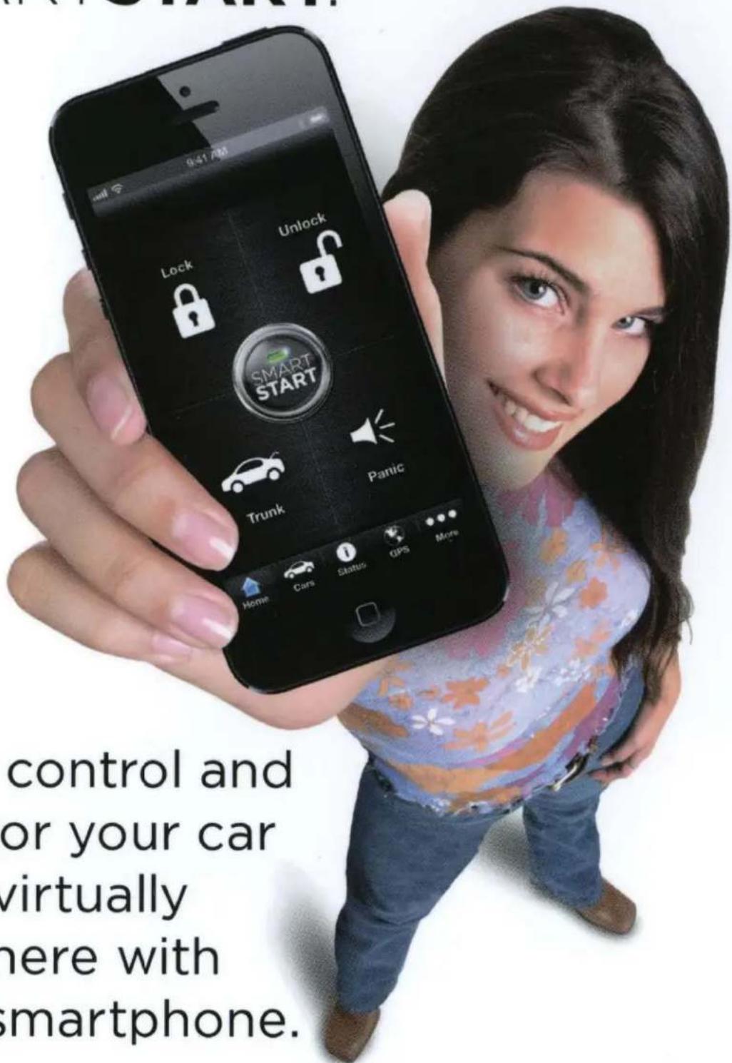
Start, control and monitor your car from virtually anywhere with your smartphone.
Ask your dealer for more information.
DIRECTED.

What can SMARTSTART™ do for you?
Remote Start
Whether it's blazing hot or freezing cold outside. Start your vehicle from your smartphone and make the temperature just right.
SmartSchedule
Never remember? SMARTSTART can look at your local weather and time to remind you that it is time to start your vehicle.
Remote Access
Never lock your keys in your car again. Lock, unlock, pop your truck, or panic alert your vehicle from virtually anywhere with your smartphone.
Vehicle Diagnostics
Always know the health of your vehicle. Diagnostic Trouble Codes (DTC) delivered right on your smartphone.
Roadside Assistance
Locked out? Dead battery? Need a tow? SMARTSTART's got your back. Free 24/7/365 roadside assistance comes with all SMARTSTART SECURE service plans.
Teen Driver Safety
Keep your family safe. Always know where they should and shouldn't be with SmartFence and HotSpot, how fast they are driving, and virtual curfews to make sure they return home safe and on time.
Home Control
Keychain weighing you down? Control access to your car and home from SMARTSTART.
www.directed.com/smartstart


- Congratulations
- What you get
- Replacement Remote controls
- Important Information
- Government Regulations and Safety Information
- Your warranty
- Contents
- Congratulations ....i
- What you get ....i
- Important Information ....ii
- Using Your System 2
- Using Remote Start ....3
- Rapid Resume Logic 8
- Remote Pairing 9
- Programming Options 10
- Battery Information 11
- Glossary of Terms....12
- Government Regulations 14
- Warning! Safety First 15
- Limited lifetime consumer warranty 18
- Commands At a Glance
- Start Engine
- Unlock Doors
- Stop Engine
- Car Finder
- Using Remote Start
- Starting the Engine:
- Key Takeover
- When you are ready to drive the vehicle:
- Note
- Safety Features
- Pit Stop and Turbo Timer Modes
- Enabling Pit Stop mode:
- Enabling Turbo Timer mode * :
- Manual Transmission Vehicles
- Enabling MTS mode
- Enabling Turbo Timer mode\*:
- Low Runtime and Remote Start Shutdown Alerts
- Optional Rear Defogger
- Starter Anti-Grind Circuitry
- Disabling the Remote Start System
- Remote Start Faults
- Rapid Resume Logic
- Remote Pairing
- To pair a new remote control to the system:
- Programming Options
- Battery Information
- Low Battery Alert
- Battery Replacement
- Battery Disposal
- Glossary of Terms
- Vehicle Security Patents
- Remote Start
- Government Regulations
- Warning! Safety First
- Installation
- Remote Start Capable
- Interference
- Upgrades
- Water/Heat Resistance
- Limited lifetime consumer warranty
- DIRECTED®
- Quick Reference Install Guide Model 4816
- Guide Translations
- Installation Points
- Learning the Tach (not needed with Virtual Tach)
- To learn the tech signal:
- Learning Virtual Tach (not needed with hardwire tach inputs)
- To program Virtual Tech:
- The learn routine exits if any of the following occurs:
- Remote Start Shutdown/Startup Diagnostics
- To perform shutdown diagnostics:
- Status LED Flashes Shutdown Mode
- Parking Light Flushes
- Turn Garage Mode on or off:
- Programming System Features
- Turn the ignition on, then all
- Once a feature is programmed:
- To access another feature in the same menu:
- To select another menu:
- The learn routine exists if any of the following occurs:
- Bitwriter - only Options
- Feature Menus
- Reset and Deletion
- Reset/delete will exit if:
- Table of Contents
- Wiring Diagram
- Wiring Connections
- Wire Descriptions
- Main Harness, 6-pin connector
- Auxiliary/Shutdown Harness, 24-pin connector
- Remote Start Heavy Gauge Harness, 8-pin connector
- Door Lock, 3-pin connector
- Initializing Virtual Tach (not needed w/hardware and data tach inputs)
- To program Virtual Tach:
- Learning Hardwired or Data Tach (not needed with Virtual Tach)
- To learn the tach signal:
- System Locking mode
- Panic Mode
- Horn Duration
- Ign-controlled Locks
- Door Lock Pulses
- Door Lock Output Duration
- Ignition Controlled 2nd Unlock
- Comfort Closure
- Hood Switch Type
- Door Switch Type
- Remote Button Unlock (Ign. OFF)
- One-time Bypass
- Override Pulse Count
- Door Open Error Chirp
- OEM Alarm Disarm with Aux/Trunk (Green/Black wire, 24-pin harness)
- OEM Alarm Disarm Output (Green/Black wire, 24-pin harness)
- OEM Alarm Disarm Pulses (Green/Black wire, 24 pin harness).
- AUX 1 Output Type (White/Violet wire, 24-pin harness)
- AUX 1 Linking
- AUX 2 Output Type
- AUX 2 Linking
- AUX 3 Output Type
- AUX 3 Linking
- AUX 4 Output Type
- AUX 4 Linking
- Aux/Trunk Output Type
- Transmission Mode
- Engine Checking Mode
- Cranking Time
- Remote Start Runtime
- Activation Pulse Count
- Turbo Mode
- Timer Mode Runtime
- Ignition 2/Flex Relay Function
- Diesel Start Delay
- Pairing a Remote Control
- LCD 2-Way Remote Control:
- Vehicle Setup for Pairing:
- To exit Pairing Mode on the remote:
- To exit Pairing Mode on the system:
- LED 2-way or 1-way Remote Control:
- Button 2-way or 1-way Remote Control:
- Basic Remote Functions
- Troubleshooting: Keyless Entry
- System does not Auto re-lock:
- Troubleshooting: Remote Start
- MTS (Manual Transmission Start) diagnostics
- MTS mode exiting diagnostics
- WARNING
- VEHICLE EQUIPPED WITH A DIRECTED REMOTE START SYSTEM
- ADVERTENCIA
- VEHÍCULO EQUIPADO CON UN SISTEMA DE ARRANQUE A DISTANCIA
- AVERTISSEMENT
- VÉHICULE ÉQUIPÉ D'UN DÉMARREUR À DISTANCE DIRECTED
- Your new system is compatible with SMARTSTART.™
- What can SMARTSTART™ do for you?
- SmartSchedule
- Remote Access
- Vehicle Diagnostics
- Roadside Assistance
- Teen Driver Safety
- Home Control
Brand : Viper
Model : 4816V
Category : Remote control