
Model 5305V - Remote control Viper - Free user manual and instructions
Find the device manual for free Model 5305V Viper in PDF.


| Product Type | Remote control for security/keyless entry and remote start system |
| Brand | Viper |
| Model | 5305V |
| Remote Control Type | 2-way LCD and 1-way companion |
| Battery (2-way remote) | 1.5V AAA (1 battery) |
| Battery (1-way remote) | Two 3V CR2016 or one 3V CR2032 |
| Battery Level Indicator | 4-level visual indicator; chirp and flashing when low |
| Operating Frequency | Complies with Part 15 of FCC rules and RSS 210 of IC |
| Range | Varies with conditions; not specified |
| Key Functions | Arm/lock, disarm/unlock, panic, silent mode, trunk release, remote start, timer mode |
| Security Features | Warn Away, triggered response, multi-level arming, high security disarm, NPC |
| Remote Start | 12/24/60 min runtime, pit stop mode, short-run turbo mode |
| Control Center | Antenna, LED status, button for valet/override |
| Valet Mode | Disables auto arming and starter kill; convenience functions remain |
| Passive Arming | Automatic arming 30 sec after door close |
| Multi-car Capability | Controls up to 4 vehicles with 2-way remote |
| Compatibility | Fuel-injected, automatic transmission vehicles only |
| Installation | Professional installation by authorized Directed dealer required |
| Warranty | Limited lifetime on control module; 1 year on accessories |
| Maintenance | Battery replacement only; no other regular maintenance |
| Included | 1x 2-way LCD remote, 1x 4-button 1-way remote, owner's guide |
| Replacement Remotes | Order via dealer or www.directedstore.com |
| SmartStart Compatible | Yes (optional module) |
Frequently Asked Questions - Model 5305V Viper
User questions about Model 5305V Viper
0 question about this device. Answer the ones you know or ask your own.
Ask a new question about this device
Download the instructions for your Remote control in PDF format for free! Find your manual Model 5305V - Viper and take your electronic device back in hand. On this page are published all the documents necessary for the use of your device. Model 5305V by Viper.
USER MANUAL Model 5305V Viper
Congratulations on the purchase of your state-of-the-art security/keyless entry and remote start system. Reading this Owner's Guide prior to using your system will help maximize the use of your system and its many features. For more information please visit us online (see back cover for URL). For any additional questions please contact your authorized Directed dealer or Directed at 1-800-753-0600. Additional support is also available at: http://support.directed.com
Note: The system you have purchased is either a security or keyless entry system. This guide covers both, however, some features are applicable to security systems only. These features are indicated by "security only" next to the section and subsection headings.
What's included
• One 2-way LCD remote control
• One 4-button 1-way remote control
- This owner's guide
Government Regulations and Safety information

Read the Government Regulations and Warning! Safety First sections of this manual prior to operating this system.
Warning! Failure to heed this information can result in death, personal injury or property damage and may also result in the illegal use of the system beyond its intended purpose.
This product is designed for fuel-injected, automatic transmission vehicles only. Installing it in a standard transmission vehicle is dangerous and is contrary to its intended use. If your vehicle is equipped with a manual transmission cease use of this product and immediately return the vehicle to an authorized Directed dealer.
Your warranty
Your system comes with a warranty. The warranty terms are detailed at the end of this guide. Make sure that you receive the proof of purchase from your dealer, indicating the product was installed by an authorized Directed dealer.
Replacement Remote controls
Please see your authorized dealer or visit us at www.directedstore.com to order additional remote controls. Remote control part numbers are found on the back of the device.
Contents
Congratulations ....i
What's included ....i
Important information ....ii
Your warranty....ii
Replacement Remote controls ....ii
LCD 2-way Remote Control ....3
Control Center 3
LCD Icons at a Glance 4
LCD Icon Description ....5
Basic Commands 7
Arm/Lock 7
Panic 7
Disarm/Unlock....7
Silent Mode 7
For optional function (trunk release) 8
Remote Start 8
Advanced Commands 9
Additional Auxiliary Functions. 9
Timer Mode 9
Short-run Turbo Mode 11
Optional Rear Window Defogger 11
Multi-car Control Capability 11
Paging Features 12
Remote and System Operations 13
Passive Arming/Locking 13
Warn Away Response (security only) 13
Triggered Response (security only) 14
Multi-level Security Arming (security only) 15
Arming While Driving (security only) 15
High Security Disarm (security only) 16
System (Emergency) Override 16
Valet Mode 17
Remote Start 18
Pit Stop Mode 19
Nuisance Prevention Circuitry 20
Power Saver Mode 21
Diagnostics (security only) 22
Arming Diagnostics 22
Disarming Diagnostics 22
Programming the LCD Remote Control 24
To enter programming mode: 24
To exit programming mode: 25
Owner Recognition 26
Rapid Resume Logic 26
Programming Options 27
Security & Convenience Expansions 30
System Maintenance....32
Battery Level Indicator, 2-way 32
Battery replacement, 2-way remote control....32
Battery replacement, 1-way remote control....32
Glossary of Terms....33
Patent Information 35
Government Regulations 36
Warning! Safety First 37
Limited lifetime consumer warranty 40
LCD 2-way Remote Control
| Feature Description | |
| Internal Antenna Used for transmitting and receiving information. | |
| Display Displays command response feedback and system states. | |
Command buttons (4)    | Used to perform arming/locking, disarming/unlocking, auxiliary channel* and remote start** commands. |
| Programming button P | Located on the back of the remote control, selects the vehicle to control and also provides user selection of LCD remote control response options. |
* On some remote controls, the icon may exist instead of the AUX icon. This guide uses the AUX throughout, but functionality is the same regardless of which one of these icons is used with your system.
Control Center
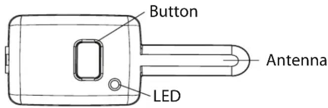
The Control Center, typically located on the upper part of the front windshield sends and receives commands or messages to and from your system. It consists of:
- The In-vehicle system antenna: for two way communication.
- The control center LED: a visual indicator of the system's status.
- The control center button: for placing the system into Valet Mode* and to perform the Emergency Override* operation.
* See "Remote and System Operations" on page 13 for details.
LCD Icons at a Glance

| Item Description Item Description | ||
| 1 Transmit 10 Battery level indicator | ||
| 2 Out of range 11 Remote start | ||
| 3 Receive 12 Remote sending | ||
| 4 Aux channels & alarm zones 13 Vibrate mode | ||
| 5 Warn away 14 Ignition | ||
| 6 Audible mode 15 Vehicle number | ||
| 7 Alarm 16 Door | ||
| 8 Trunk or Hood | 17 Arm | |
| 9 Sensor | 18 Disarm |
Icon Description
 | On during remote command transmission to the vehicle. |
 | On during remote command transmission to vehicle, but command page is not received. |
 | On during receipt of page from the vehicle to the remote. |
 | Displays which auxiliary channel or alarm trigger zone is active. |
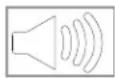 | Alarm icon displays when beep notification is turned on and disappears when beep notification is turned off (see "Programming the LCD Remote Control" on page 24). |
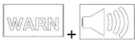 | Displays when a security feature is tripped, but not to full alarm. |
 | Displays when a security feature is tripped to a full alarm state. |
 | Trunk icon flashes a few seconds during full alarm and then remains displayed until page is cleared. |
 | Shock sensor icon flashes a few seconds during Warn Away and full alarm, and then remains displayed until page is cleared. |
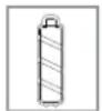 | Battery icon displays current charge capacity of the remote's battery. |
 | Displays when remote start is active, engine is running. |
 | Bar indicates remote is sending. |
 | Vibrator icon displays if remote is programmed for vibrator notification (see "Programming the LCD Remote Control" on page 24). |
Icon Description
 | Ignition icon flashes a few seconds during full alarm, then remains displayed until page is cleared. |
 | Hood icon flashes a few seconds during full alarm, and then remains displayed until page is cleared. |
 | Displays the vehicle (1 of 4) that the remote controls. If a Warn Away or alarm trigger occurs at other vehicle, that vehicle number is displayed in the vehicle status. |
 | Door icon flashes a few seconds, and then remains displayed until page is cleared. |
 | Arm icon flashes when doors are locking, and then remains displayed until the system is disarmed. |
 | Disarm icon flashes when doors are unlocking, and then remains displayed until the system is armed. |
Basic Commands
Note: Button configuration also applies to the 1-way remote control.
Arm/Lock
Press and release 🔒
The alarm arms, doors lock (if connected), and the siren/horn sounds and parking lights flash once. If Valet mode* is On, the doors lock with no audio confirmation and the arm/lock indicator** is displayed. Exit Valet mode to arm/lock the alarm normally.
Panic
Press and hold
The alarm Arms (or Locks in Valet) and, after two seconds, sounds the siren/horn and flashes the parking lights. Press and release again to stop panic.
Disarm/Unlock
Press and release
The alarm disarms, doors unlock (if connected), and the siren/horn sounds and parking lights flash twice. Also turns panic off if on. If Valet mode* is On, the doors unlock with no chirp confirmations and the disarm/unlock indicator** is displayed. Exit Valet mode to disarm/unlock the alarm normally.
Silent Mode™
Press and release AUX

Perform before the Arm/lock or Disarm/unlock command to use the remote control in Silent Mode ^TM .
For optional function (trunk release)
Press and hold AUX

Activates the Aux output, such as trunk release or an expansion function that you have added to your system.
The auxiliary output controls: ____.
Remote Start
Press and release ✱
Activates (or if On, deactivates) the remote starter. The engine and parking lights turn On.
Note: The factory setting is one press, but this can also be programmed for two presses (See your authorized Directed installer for the amount of presses programmed).
Record the mount of presses to activate remote start here: ____
* See "Remote and System Operations" on page 13 for details.
** 2-way remote control only
Advanced Commands
Note: Button configuration also applies to the 1-way remote control.
Additional Auxiliary Functions.
Press 📄 and AUX simultaneously
Activates the optional auxiliary 4 convenience or expansion function that you have added to your system.
The auxiliary output controls ____
Press and buttons simultaneously
Activates the optional auxiliary 5 convenience or expansion function that you have added to your system.
The auxiliary output controls ____
Press and buttons simultaneously
Activates the optional auxiliary 6 convenience or expansion function that you have added to your system.
The auxiliary output controls ____
Timer Mode
Press 🔒 and buttons simultaneously
There are two types of timer modes and the system can be programmed to perform either one or the other, the factory setting is timed mode. In timed mode, the system allows you to keep the engine warm by automatically activating the remote start every three hours for a maximum of six starting cycles.
The temperature mode checks every three hours to see if the temperature threshold of 0^ F has been met or exceeded. If met or exceeded, the vehicle then remote starts and runs for the programmed time, and will check again three hours after shutting off. However, if the thresh-
old isn't met or exceeded, then the remote start does not activate, but will check again later after another three hours have elapsed.
Note: The timer mode features are activated and deactivated the same way, with the temperature mode automatically exiting after 18 hours.
To activate:
-
Park the vehicle and set the parking brake.
-
Press the 🔒 and 🔒 buttons simultaneously.
-
The parking lights flash slowly four times.
-
The remote start activates and runs for the set duration. The system remains remote started unless shut down by pressing the button on the remote.
-
Once the remote start shuts down, the vehicle will start every three hours for a maximum of six cycles or until timer mode is canceled by turning on the ignition or activating any of the shutdowns (the parking lights flash slowly four times to confirm Timer Mode is exited).
To deactivate timer mode, turn on the ignition or activate any of the remote start shutdowns (arming and disarming the system or pressing the 🔒 and 🔒 buttons on the remote will not exit the timer mode). The parking lights flash four times confirming timer mode is exiting.
Note: The feature exits (if active) when the vehicle is driven, so if timer mode is desired, it needs to be activated again.
Short-run Turbo Mode
Press and buux simultaneously
Short-run turbo mode keeps the engine running for a programmable period of time after arriving at your destination (check with your authorized Directed dealer for available run times). This allows the system's timer to conveniently cool down the turbo after you have left the vehicle.
To activate:
- Park the vehicle and set the parking brake.
- Remove your foot from the brake pedal and leave the engine running.
- Press the × and AUXs simultaneously
- The parking lights flash to indicate the remote start has entered the short-run turbo mode.
- Turn the key to the off position and the engine will continue to run.
- Exit and secure the vehicle.
- The engine will shut off after the programmed runtime expires.
Optional Rear Window Defogger
When the feature is programmed on, the rear defogger automatically activates during the remote start sequence if the temperature at the control module is below 55^ F. If the temperature is greater than 55^ F at the control module when the remote start is activated, the rear defogger does not turn on.
Multi-car Control Capability
Your 2-way remote control can operate up to four vehicles with full command capability for all vehicles.
To change the Vehicle to be operated:
Press the P button on the back for one second then release, each time
the button is released the vehicle control indicator will change.
While the system is armed, if the Warn Away or full alarm is triggered on any of the programmed vehicles, that vehicle's number will be displayed and the LCD will display that vehicle's status. To change back to the original vehicle that was selected press the P button for one second and release until the desired vehicle number is shown.
For example, if the remote was originally on vehicle number 1 and a trigger page was received for vehicle number 2, the remote will show the alarm trigger and show number 2 on the display. After clearing the page, you can select the desired vehicle to be controlled.
Note: This feature is only applicable to the 2-way remote control.
Paging Features
The control module sends a page to the remote as confirmation of a received command, or alarm system status.
When the remote receives a page notification, it beeps or vibrates and the alarm status, armed/locked or disarmed/unlocked, (the lock or unlock icon) appears on the LCD. If the alarm has been triggered, the remote LCD displays the zone triggered. To clear the alarm page, press any button on the remote. The LCD information is also cleared.
Note: You will not be able to send a command, until the alarm page is cleared.
Remote and System Operations
Passive Arming/Locking
The system can be programmed to arm/lock itself automatically (called passive arming/locking). If the system is programmed for passive arming/locking, it will automatically arm/lock 30 seconds after the ignition is turned off and the system detects that you have left the vehicle by opening and closing a door. Whenever the system is in its 30-sec and passive arming/locking count down, the status LED will flash twice as fast as it does when the system is armed/locked. At the 20-second point of the countdown, the siren/horn will sound to indicate that the system is about to arm/lock. At the 30-second point, the parking lights will flash to indicate that the system is armed/locked.
Note: If any protected entry point (such as a door or a switch-protected trunk or hood) is open, the system will not passively arm/lock (unless forced passive arming/locking is programmed on). See "Forced passive arming" under "Programming Options" on page 27 of this guide.
Warn Away® Response (security only)
A Warn Away Response consists of an alarm page along with the responses described below.
- Shock (impact) Sensor - Light impacts to the vehicle will flash the vehicle lights and sound the siren/horn for a few seconds.
- 2-way Remote Control Notification - Ten quick beeps (or one vibration).
- The 2-way remote control will enter Page Recognition Mode and operate alarm page alerts.
Triggered Response (security only)
A Triggered Response can be activated by any of the triggers listed below and consists of an alarm page along with the response described for each trigger. The default Triggered Response duration is 30 seconds but can be programmed from 1-180 seconds by your installer.
- Shock Sensor Trigger - Heavy impacts to the vehicle will instantly sound the siren/horn and flash the lights for the programmed duration and report Zone 2.
- Door Trigger - If a door is opened the siren/horn will sound and lights flash for three seconds, then the siren/horn will sound continuously and the lights will flash for the programmed duration and report Zone 3. The three seconds allow the user time to disarm/unlock the system with a minimum of noise should a door be opened inadvertently while the system is armed/locked.
- Hood Trigger - Opening the hood will sound the siren/horn, flash the lights for the programmed duration, and report Zone 6.
- Trunk Trigger - Opening the trunk (if connected) will instantly sound the siren/horn and flash the lights for the programmed duration and report Zone 1.
- Ignition Trigger - Turning on the ignition key will trip the same progressive re sponse as the door trigger and report Zone 5.
When a Triggered Response is activated the 2-way remote control will:
- Repeat four quick beeps (or vibrate) for 15 seconds.
- The full trigger alert icon will turn on for 15 seconds.
Multi-level Security Arming (security only)
Multi-Level Security Arming allows you to select which of the security system's inputs or sensors are active, or are bypassed when the system is armed (See the "Table of zones" on page 23 of this guide).
Press 🔒 one time to arm the system, siren chirps one time. Pressing 🔒 again activates Multi-Level Security Arming.
Each time 🔒 is pressed consecutively, a different security level is selected, as described in the below table:
| Press | Siren chirps Zone bypassed |
| 2 times 2 times followed by 1 long chirp 2 | |
| 3 times 3 times followed by 1 long chirp 4 | |
| 4 times 4 times followed by 1 long chirp 2 & 4 | |
| 5 times 5 times followed by 1 long chirp all zones except 5 | |
Each press of the 📄 button ascends to the next security level, the remote sounds one beep, and the lock icon flashes five times.
Multi-Level Security Arming applies to a single arming cycle. The next time the system is armed, all the zones will be active again.
Arming While Driving (security only)
Your security system can be armed while driving the vehicle. Press 🔒 on the remote control for two seconds while the vehicle is running. The siren/horn will sound once to indicate that the security system is armed, and then once more to indicate that the ignition is on. The system will not respond to any input except the door triggers, and the starter kill relay (if installed) will not be activated. Once you have
arrived at your destination, the system will disarm when the ignition is turned off. The siren/horn will sound twice and the LED will then stop flashing. The system can also be disarmed at any time by pressing 🔒
High Security Disarm (security only)
High Security Disarm makes it possible to silence and reset the system when it is triggering, without disarming. If the system is triggered, and the siren sounds for longer than six seconds, pressing the 🔒 button will stop the trigger and return the system to an armed state. The system does not disarm, but rather reset. This prevents you from disabling the system should you want to disarm without visually checking the vehicle. Pressing the 🔒 button again after resetting the system, will disarm the system. Pressing the 🔒 button during the first six seconds of the triggered sequence disarms the system immediately. The six second timer is provided for your convenience, in case you accidentally trigger the system.
System (Emergency) Override
If your remote control is lost or damaged, you can manually disarm your vehicle security system or disable the optional starter kill. To disarm or disable the system without a remote control, you must have the vehicle's ignition key.
To disarm/disable the system:
- Turn the ignition to the ON position.
- Press and release the control center button the preset number of times (one to five times) within 15 seconds (the factory default setting is 1 press). After five seconds, the system will disarm/disable. If the system does not disarm/disable, you may have waited too long. Start over by turning the ignition off and on.
Number of Presses ____
Important: The control center button can be programmed to respond from one to five presses for the disarm/disable function. You must check with the installer to verify the programming for your individual unit.
Valet Mode
You can prevent your system from automatically arming/locking and triggering by using Valet Mode. This is very useful when washing the vehicle or having it serviced. In Valet Mode, the system/starter kill will not arm/enable, even with the remote control, but all convenience functions (door locks, trunk re lease, etc.) will continue to work nor mally.
To enter or exit Valet Mode:
- Turn the ignition on.
- Turn the ignition off.
- Press and release the control center button within 10 seconds.
To enter or exit Valet Mode using the remote control:
- Open any vehicle door.
- Press 🔒.
- Press 📋 and then press 📋 again.
The status LED lights solidly if you are entering Valet Mode, and goes off when you exit Valet Mode.
Note: The 2-way remote flashes the 📋 for three seconds when entering valet mode and flashes the 📋 for three seconds and beeps twice when exiting valet mode. It does not offer arm/disarm confirmations when the system is in valet mode.
Remote Start
This feature allows you to remotely start and run your vehicle for a program ma ble period of time. This makes it possible to warm up the engine, as well as adjust the interior temperature of the vehicle with the climate control system. If interior heating or cooling is desired, the climate controls must be preset, and the fan blower must be set to the desired level prior to remote starting the vehicle.

Warning! (1) Never remote start your vehicle when the keys are in the ignition, except when performing Pit Stop mode, and (2) Never start the vehicle if it is not in PARK or NEUTRAL. (3) Do not activate the remote start if the vehicle has a manual transmission.
To remote start the vehicle:
- Ensure the parking brake is set, press ✝ on the remote control once (or the amount of times the system has been programmed to activate the remote start, see "Remote Start" on page 8).
The parking lights flash to confirm that the vehicle will attempt to start. With gas vehicles the engine starts four seconds after the parking lights flash. With diesel vehicles the engine starts when the WAIT-TO-START indicator on the dashboard goes out or the programmed delay has ended.
Once the vehicle has started, it runs for the pre-program med period of time (either 12, 24, or 60 minutes; See Programming Options section) or until a shutdown input is triggered.

Warning! It is unsafe to operate a vehicle's motor in a garage or other closed off area. Breathing the exhaust from the vehicle is hazardous to your health. Never activate the remote start in an enclosed space.
When you are ready to drive the vehicle:
- Insert the ignition key and turn it to the On position.
- Press the brake pedal.
- Disengage the parking brake.
- Place the vehicle in gear and drive to your destination.
Note: If the brake pedal is pressed or the parking brake is disengaged before the key is in the ON position, the engine will shut down.
While the vehicle is running during remote start operation, the system monitors the vehicle and automatically shuts down the engine if the system receives any of the following:
• The brake pedal is pressed
- The hood is opened
- The shutdown toggle switch is put into the Off position
• The parking brake is disengaged
• Runtime (12, 24, or 60 minutes) expires
- The remote start activation procedure from the remote is repeated.
Pit Stop Mode
The Pit Stop mode feature allows the vehicle to remain running after the key has been removed from the ignition. This feature is useful for occasions when you wish to exit and lock the vehicle for short periods of time, but would like to leave the motor running and the climate controls on.
To perform Pit Stop mode:
-
Before turning off the engine, ensure that the parking brake is set. Press and release ✝ on the remote the amount of times the system has been programmed to activate the remote start (or press and release the optional momentary switch). Then wait five seconds.
-
Turn the ignition key to the OFF position, the engine will continue running.
- Exit and secure the vehicle
- When returning to the vehicle simply disarm the system and follow the previous "When you are ready to drive the vehicle" information.
Note: If you are away from the vehicle for an extended amount of time, the remote start will shut off after the programmed runtime expires or when a shutdown input is received (see the previous Remote Start section for a complete list of shutdown inputs).
This feature will not work if the brake pedal is being pressed or the parking brake is disengaged.
Nuisance Prevention Circuitry
Your system has Directed's Nuisance Prevention Circuitry® (NPC). It prevents annoying repetitive trigger sequences due to faulty door pin switches or environmental conditions such as thunder, jackhammers, or airport noise.
For example, if the alarm triggers three times within a 60 - minute period and each time the same sensor or switch triggers the alarm, NPC will interpret those triggers as false alarms. After the third trigger, NPC ignores, or bypasses, that sensor or switch (along with any other sensors or switches sharing the same zone) for 60 minutes.
If the bypassed sensor tries to trigger the system while it is being bypassed, the 60 - minute bypass period starts over. This ensures that a sensor that continually triggers will remain bypassed.
Doors are covered by NPC differently - if the alarm is triggered by an open door for three full cycles, the doors are bypassed until the trigger ceases.
NPC is On/Off programmable, except doors are always covered whether on or off. See your dealer and the Programming section of this guide for more information.
Arming and disarming the system does not reset this function. In order to reset a bypassed zone, the same zone must not trigger for 60 minutes, or when ignition is turned on. If testing your system, it is important to remember that the NPC programming can cause zones to be bypassed and appear to stop working. If five chirps are heard when disarming, NPC has been engaged. If you wish to clear the NPC memory, turn the ignition key on.
Power Saver Mode
Your system will automatically enter Power Saver Mode while armed or in Valet® Mode, after a period of time in which no operation has been performed. This lowers the current draw to the vehicle's battery. Power Saver Mode takes over under the following conditions:
- Power Saver when the system is armed: After the system has been armed for 24 hours, the control center LED will flash at half its normal rate, decreasing the system's current draw.
- Power Saver in Valet Mode: When the system enters Valet Mode the control center LED illuminates steadily. If the vehicle is not used (ignition is not turned on) for a period of one hour while the system is in Valet Mode, the LED will shut off. If the system remains in Valet Mode, the LED will come back on the next time the ignition is turned on and then back off.
Diagnostics (security only)
The microprocessor at the heart of your security system is constantly mon i tor ing all of the switches and sensors that are connected to it. It de- tects any faulty switches and sensors and prevents them from disabling the entire system. The microprocessor will also record and report any triggers that occurred during your absence. Refer to the System Status Chirps and Table of Zones charts for diagnostic information.
Arming Diagnostics
If the system is armed while an input is active - door open, sensor triggering - the unit will chirp once when arming and then one more time a few seconds later. This is called Bypass Notification.
Bypass Notification will not occur when using Silent Mode or if chirps have been programmed OFF. The security system will continually ignore the zone that was active until the input stops. Three seconds after the input stops, the system monitors that input normally. For example, if your vehicle has interior light exit delay, and you arm it before the interior light goes out, you may hear Bypass Notification chirps. Once the light shuts off, the doors are mon i tored normally.
Disarming Diagnostics
Extra disarm chirps are the Tamper Alert. If four chirps are heard when disarming, the system was triggered in your absence. If five chirps are heard, a zone was triggered so many times that Nuisance Prevention® Circuitry has bypassed that zone (see "Nuisance prevention circuitry" on page 20 of this guide).
The control center LED indicates which zone was involved (see "Table of Zones" on page 23). The system retains this information in its
memory, and continues to chirp four or five times each time it is disarmed, until the next time the ignition key is turned on.
Table of Zones
A zone is represented by the number of control center LED flashes used by the system to identify a particular type of input. Standard input assignments are listed in the following table, along with spaces to write in any optional sensors or switches that have been installed.
| Zone Description Dealer installed options | ||
| 1 Trunk Pin | ||
| 2 Instant trigger: a heavier impact detected by the shock sensor | ||
| 3 Door switch trigger | ||
| 4 Instant trigger: for optional sensors | ||
| 5 Ignition trigger | ||
| 6 Hood Pin | ||
Interpreting Zone Diagnostics
Warn Away responses are not reported by arming or disarming diagnostics. If you receive a Bypass notification when arming or a Tamper Alert notification when disarming, look at the LED in the vehicle. Active or triggered zones will be indicated by a pattern of blinks by the LED.
For example: If zone 3 was active or triggered, the LED will blink three times with a two-second pause. Then it will blink three times again, and repeat until the ignition is turned on.
Your system stores the last two triggered zones in memory. If your system has been triggered but the LED has been reset by turning on the ignition, your dealer can still recall the last two zones that were triggered. Contact your dealer for details.
Programming the LCD Remote Control
To enter programming mode:
Press and hold the P button on the back of the remote control until one long beep sounds. You can now customize the remote's response feedback. Note: If no buttons are pressed within five seconds, programming mode is exited; the remote sounds two beeps.
Beeps and Vibration, On/Off
Press ☐ to select beep/vibration On or Off, or one of the below settings.
| Beeps/Vibrate Response Icon* | ||
| Beeps only 1 beep |  | |
| Vibrate only 1 vibrate |  | |
| Beep & Vibrate 1 beep & 1 vibrate |   | |
| No Beep & No Vibrate 1 long beep | ||
*Displays during programming
Illumination On/Off
Press 📄 to select LCD backlight illumination On/Off. The LCD back-light will illuminate when a remote button is pressed, or an alarm status page is received.
| LCD backlight settings Programming | |
| On 1 beep backlight On | |
| Off | 2 beeps backlight Off |
Page Notification
The remote control can notify the user of a page by emitting beeps if the vehicle's status changes. For example, any vehicle violation such as a door being unlocked.
Press ✧ to select page On/Off. One beep is page On. Two beeps is page Off.
| Page notification Response |
| On 1 beep |
| Off 2 beeps |
Note: When programmed Off, responses are only received when a command from the remote control is performed. However, alarm trigger pages are not received.
To exit programming mode:
The LCD remote control will exit programming mode after five seconds of inactivity and will emit two long beeps.
Owner Recognition
Owner Recognition is a feature available exclusively from Directed. Using the Directed Bitwriter®, a hand-held programming tool, your dealer can program many of the system settings. The programmer makes it possible to program different settings for each remote control that is used with the system. Then, whenever a specific remote control is used, the system will recall the settings assigned to that remote control. Owner Rec og ni tion lets up to four users of the system have different settings that meet their specific needs. It is almost like having four separate alarms in your vehicle, one for each user.
Owner Recognition cannot be programmed without a Directed Bitwriter and the necessary soft ware. Check with your dealer for more information.
Rapid Resume Logic
This Directed system will store its current state to non-volatile memory. If power is lost and then reconnected, the system will recall the stored state from memory. This means if the unit is in Valet Mode and the battery is disconnected for any reason, such as servicing the vehicle, when the battery is reconnected the unit will still be in Valet Mode. This applies to all states of the system including arm, disarm, and Valet Mode.
Programming Options
Programming options control what your system does during normal operation, and require few or no additional parts. However, some may require additional in stalation labor.
The following is a list of the program settings, with the factory settings in Bold:
• Active arming (only with the remote) or passive arming (automatic arming 30- seconds after the last door has been closed).
- Arming/disarming confirmation siren chirps On or off.
- The ignition controlled door lock feature On or Off: With this feature on, the doors will lock three seconds after the ignition is turned on, and the doors are closed, and unlock when the ignition is turned off. With this feature off, the system will not lock the doors when the ignition is turned on and will not unlock the doors when the ignition is turned off. Ignition lock and unlock are independent features and can be programmed separately, when using the Bitwriter.
- Passive door locking (with passive arming) or active door locking (only when arming with the remote). Passive locking allows the vehicle's doors to lock when the security system passively arms (after the 30 second countdown). This feature only works if passive arming has been programmed. When programmed for passive arming and active lock, if the system is disarmed without a door being opened, the system will re-lock the doors when it passively rearms.
- Panic mode enabled/disabled with the ignition on: Some states have laws against siren capability in a moving vehicle.
- Forced passive arming On or off: If your system is programmed for passive arming and the forced passive arming feature has been programmed on, the system will passively arm after one hour, even if a protected entry has been left open. This feature is useful if a door has been left ajar when leaving the vehicle. Forced passive arming ensures that the security system will be armed in every situation.
When the system passively arms after one hour, the entry point that has been left open, and anything connected to the same zone, is bypassed and cannot trigger the system. However, the re main ing inputs to the system are fully operational.
- Automatic Engine Disable (AED) on or Off: The purpose of this feature is to protect the vehicle from being stolen at all times, regardless of whether or not the alarm is armed. If AED is programmed on, the starter of the vehicle will be disabled 30 seconds after the ignition is turned off. Once the key is turned off, the in-vehicle LED will flash slowly (one-half its normal armed rate) to indicate the AED arming cycle. Thirty seconds later, the starter of the vehicle will be disabled.
To start the vehicle, it will be necessary to disarm the system with the remote. It is also possible to disarm the AED feature by turning the ignition key to the RUN position and pressing the Control center button the programmed number of times. AED is disabled when the system is in Valet Mode. This feature only functions if the Failsafe® Starter Kill relay has been installed.
- Full trigger response 30 or 60 seconds: This determines how long the full triggered sequence lasts. Some states have laws regulating how long a security system can sound before it is considered a nuisance. If your installer is programming the security system with the Directed Bitwriter, the full triggered response can be programmed for any duration ranging from 1 to 180 seconds.
- Nuisance Prevention Circuitry On or off: Please refer to the NPC section of this manual for a complete explanation of how NPC operates. If NPC is programmed off, the security system will respond to inputs from any sensor in definitely ly.
Because many states have laws regulating security systems, program ming NPC off may cause your system to violate state laws.
- Progressive door trigger On or off: When the system is armed and a door is opened, the system responds with ten chirps prior to beginning the full triggered sequence. If an instant trigger is desired, the progressive door trigger can be programmed off.
- Valet pulse count: The number of presses of the Control center button required to disarm the security system or AED, the system can be programmed from one to five presses.
- Comfort Closure: Windows will close upon arming the system.
Security & Convenience Expansions
Listed are some of the many expansion options available. Please contact your dealer to find out about all the convenience options available to you.
Audio Sensor: Metal on glass, cracking glass, and breaking glass each produce dis tinc tive acoustic signatures. The 506T audio sensor uses a microphone to pick up sounds, and then using proprietary acoustic software, analyzes the sounds to determine if the glass was struck.
Backup Battery: The 520T keeps the system armed, triggers the alarm and keeps the starter kill active if main battery power is dis connected.
Field Disturbance Sensor: An invisible dome of coverage is established by installing the 508D "radar" sensor. Your security system can then react to any intrusions into this field with the triggered sequence.
Headlight and Parking Light Automation: The 545T Nite-Lite will auto-mat i cal ly turn on your parking and headlights when it gets dark. In addition, the 545T will turn your headlights on whenever the windshield wipers are used. A remote control function can also be used to turn on your parking and headlights for a programmed time.
Power Trunk Release: The trunk release output of the system can operate a factory power release for the vehicle's trunk or hatch. (An additional relay may be required.) If the factory release is not power activated, then Directed's 522T trunk release solenoid can often be added.
Power Window Control: Automatic power window control is provided with the 529T and 535T systems.
Tilt Sensor: The 507M tilt sensor can be added to your system to protect your vehicle when its parked. An alarm is triggered if the vehicle is lifted, to protect expensive rims.
Ultrasonic Sensor: Provides a field of protection inside your vehicle, the 509U Ultrasonic sensor, protects your belongings.
System Maintenance
This system needs no specific maintenance beyond remote control battery replacement. The 2-way remote control is powered by one 1.5V AAA battery. The 1-way remote control is powered by either two 3V, CR2016 batteries or one 3V CR2032 (see back of remote for details).
Battery Level Indicator, 2-way
The Battery Level indicator has four level indicators that serve as a visual indication of battery charge. When the battery reaches a low charge level that requires replacement, the remote control generates a single notification chirp, and the Battery Level indicator flashes continuously.

Battery replacement, 2-way remote control
- Gently pull the end of the battery door away from the top of the remote control then slide the door up to expose the battery.
- Replace the expired battery with a new battery, observing the correct polarity.
- Reinstall door and close to latch. When power is returned, the remote control plays a melody and all icons in the LCD are displayed. Press any button on the remote to stop the melody.
Battery replacement, 1-way remote control
- Using a small flat-head screwdriver, insert into slot located along the edge of the remote control and carefully pry the unit open.
- Turn unit over and carefully remove rear housing. Remove the battery from holder and replace with a new one.
- Reassemble all parts and snap together.
Note Verify that the battery polarity is correct when replacing.
Battery Disposal

Directed cares about the environment. If you need to dispose of the battery, please do so in accordance with your municipal requirements for battery disposal.
Glossary of Terms
Document Terminology
| Control Module (unit) | The “brain” of your system. Usually hidden under the dash area of the vehicle. It houses the microprocessor which monitors your vehicle and controls all of the system's functions. |
| Control Center | The Control Center, typically located on the upper part of the front windshield houses the antenna. It sends and receives commands or messages to and from your system. |
| Control Center Button (also called: Control button or Valet switch) | A small push button on the control center, also called the control button, valet switch or valet button. It is used to override disarm the alarm when a remote is not available, to enter or exit Valet Mode, and to program the system. |
| Control Center LED (also called: Status LED) | A light mounted on the control center, used to indicate the status of your system such as triggers and faults in the system or sensors. |
| FailSafe Starter Kill | A switch controlled by the security system which once activated prevents the vehicle's starter from cranking, when the system is armed. The vehicle is never prevented from cranking when the system is disarmed, in Valet mode - or if the starter interrupt switch fails. Installation may require additional labor. |
Document Terminology
| Input | A physical connection to the system. Input may be provided by a sensor, a pin-switch or through an existing system in the vehicle, such as ignition or courtesy lights. |
| LCD | Liquid Crystal Display, the screen on the 2-way remote control. It displays the vehicle status using symbols and icons, such as alarm information. |
| Remote Control1-way Companion | A hand-held remote control, also called transmitter that commands and operates the various functions of your system but does not provide feedback. |
| Remote Control2-way | A hand-held remote control, also called transmitter, that operates the various functions of your system and receives messages and pages from the system. |
| Siren | Noise generating device usually installed in the engine compartment of the vehicle. It generates the "chirps" and the tones you hear when the alarm is triggered. |
| Trigger or Triggered Sequence | When the alarm "goes off" or "trips", the system triggers a sequence of siren sounding and parking lights flashing for a programmed duration. |
| Warn Away® | Lighter impacts to the vehicle generate a Warning Zone response, several seconds of siren chirps and parking light flashes. |
| Zone | Input that the alarm recognizes as unique. Each input is connected to a particular zone. Two or more inputs may share the same zone. |
Patent Information
This product is covered by one or more of the following United States patents:
Remote Start Patents:
5,349,931; 5,872,519; 5,914,667; 5,952,933; 5,945,936; 5,990,786; 6,028,372; 6,467,448; 6,561,151; 7,191,053; 7,483,783
Vehicle Security Patents:
5,467,070; 5,532,670; 5,534,845; 5,563,576; 5,646,591; 5,650,774; 5,673,017; 5,712,638; 5,872,519; 5,914,667; 5,952,933; 5,945,936; 5,990,786; 6,028,505; 6,452,484
Other patents pending.
Government Regulations
This device complies with Part 15 of FCC rules. Operation is subject to the following two conditions: (1) This device may not cause harmful interference, and (2) This device must accept any interference received, including interference that may cause undesirable operation.
This equipment has been tested and found to comply with the limits for a class B digital device, pursuant to Part 15 of the FCC Rules. These limits are designed to provide reasonable protection against harmful interference in a residential installation. This equipment generates and can radiate radio frequency energy and, if not installed and used in accordance with the instruction manual, may cause harmful interference to radio communications. However, there is no guarantee that interference will not occur in a particular installation. If this equipment does cause harmful interference to radio or television, which can be determined by turning the equipment OFF and ON, the user is encouraged to try to correct the interference by one or more of the following measures:
- Reorient or relocate the receiving antenna.
- Increase the separation between the equipment and receiver.
- Connect the equipment into an outlet on a circuit different from that to which the receiver is connected.
- Consult the dealer or an experienced radio / TV technician for help.
This device complies with the Industry Canada Radio Standards Specification RSS 210. Its use is authorized only on a no-interference, no-protection basis; in other words, this device must not be used if it is determined that it causes harmful interference to services authorized by IC. In addition, the user of this device must accept any radio interference that may be received, even if this interference could affect the operation of the device.
Warning:
Changes or modifications not expressly approved by the party responsible for compliance could void the user's authority to operate this device.
Warning! Safety First

Please read the safety warnings below before proceeding. Improper use of the product may be dangerous or illegal.
Installation
Due to the complexity of this system, installation of this product must only be performed by an authorized Directed dealer. If you have any questions, ask your retailer or contact Directed directly at 1-800-753-0600.
Remote Start Capable
When properly installed, this system can start the vehicle via a command signal from the remote control transmitter. Therefore, never operate the system in an enclosed area or partially enclosed area without ventilation (such as a garage). When parking in an enclosed or partially enclosed area or when having the vehicle serviced, the remote start system must be disabled using the installed menu wheel. It is the user's sole responsibility to properly handle and keep out of reach from children all remote control transmitters to assure that the system does not unintentionally remote start the vehicle. THE USER MUST INSTALL A CARBON MONOXIDE DETECTOR IN OR ABOUT THE LIVING AREA ADJACENT TO THE VEHICLE. ALL DOORS LEADING FROM ADJACENT LIVING AREAS TO THE ENCLOSED OR PARTIALLY ENCLOSED VEHICLE STORAGE AREA MUST AT ALL TIMES REMAIN CLOSED. These precautions are the sole responsibility of the user.
Manual Transmission Vehicles
Remote starters on manual transmission vehicles operate differently than those with automatic transmission because you must leave your car in neutral. You must read this Owner's Guide to familiarize yourself with the proper procedures regarding manual transmission remote starters. If you have any questions, ask your authorized Directed dealer or contact Directed at 1-800-753-0600.
Before remote starting a manual transmission vehicle, be sure to:
- Leave the vehicle in neutral and be sure no one is standing in front or behind the vehicle.
- Only remote start on a flat surface
• Have the parking brake fully engaged
WARNING! It is the responsibility of the owner to ensure the parking/emergency brake properly functions. Failure to do so can result in personal injury or property damage. We recommend the owner have the parking / emergency brake system inspected and adjusted by a qualified automotive shop biannually.
Use of this product in a manner contrary to its intended mode of operation may result in property damage, personal injury, or death. (1) Never remotely start the vehicle with the vehicle in gear, and (2) Never remotely start the vehicle with the keys in the ignition. The user must also have the neutral safety feature of the vehicle periodically checked, wherein the vehicle must not remotely start while the car is in gear. This testing should be performed by an authorized Directed dealer in accordance with the Safety Check outlined in the product installation guide. If the vehicle starts in gear, cease remote start operation immediately and consult with the authorized Directed dealer to fix the problem.
After the remote start module has been installed, contact your authorized dealer to have him or her test the remote start module by performing the Safety Check outlined in the product installation guide. If the vehicle starts when performing the Neutral Safety Shutdown Circuit test, the remote start unit has not been properly installed. The remote start module must be removed or the installer must properly reinstall the remote start system so that the vehicle does not start in gear. All installations must be performed by an authorized Directed dealer.
OPERATION OF THE REMOTE START MODULE IF THE VEHICLE STARTS IN GEAR IS CONTRARY TO ITS INTENDED MODE OF OPERATION. OPERAT-
ING THE REMOTE START SYSTEM UNDER THESE CONDITIONS MAY RESULT IN PROPERTY DAMAGE OR PERSONAL INJURY. YOU MUST IMMEDIATELY CEASE THE USE OF THE UNIT AND SEEK THE ASSISTANCE OF AN AUTHORIZED Directed DEALER TO REPAIR OR DISCONNECT THE INSTALLED REMOTE START MODULE. DIRECTED WILL NOT BE HELD RESPONSIBLE OR PAY FOR INSTALLATION OR REINSTALLATION COSTS.
This product is designed for fuel injected vehicles only. Use of this product in a standard transmission vehicle must be in strict accordance with this guide.
This product should not be installed in any convertible vehicles, soft or hard top with a manual transmission. Installation in such vehicles may pose certain risk.
Interference
All radio devices are subject to interference which could affect proper performance.
Upgrades and Batteries
Any upgrades to this product and/or installation of batteries must be performed by an authorized dealer. Do not attempt to perform any unauthorized modifications to this product.
Water/Heat Resistance
This product is not designed to be water and/or heat-resistant. Please take care to keep this product dry and away from heat sources. Any damage from water or heat will void the warranty.
Limited lifetime consumer warranty
Directed Electronics. ("Directed") promises to the original purchaser to repair or replace (at Directed's election) with a comparable reconditioned model any Directed unit (hereafter the "unit"), excluding without limitation the siren, the remote transmitters, the associated sensors and accessories, which proves to be defective in workmanship or material under reasonable use during the lifetime of the vehicle provided the following conditions are met: the unit was purchased from an authorized Directed dealer, the unit was professionally installed and serviced by an authorized Directed dealer; the unit will be professionally reinstalled in the vehicle in which it was originally installed by an authorized Directed dealer; and the unit is returned to Directed, shipping prepaid with a legible copy of the bill of sale or other dated proof of purchase bearing the following information: consumer's name, telephone number and address; the authorized dealers name, telephone number and address; complete product description, including accessories; the year, make and model of the vehicle; vehicle license number and vehicle identification number. All components other than the unit, including without limitation the siren, the remote transmitters and the associated sensors and accessories, carry a one-year warranty from the date of purchase of the same. ALL PRODUCTS RECEIVED BY DIRECTED FOR WARRANTY REPAIR WITHOUT PROOF OF PURCHASE FROM AN AUTHORIZED DEALER WILL BE DENIED. This warranty is non-transferable and is automatically void if: the unit's date code or serial number is defaced, missing or altered; the unit has been modified or used in a manner contrary to its intended purpose; the unit has been damaged by accident, unreasonable use, neglect, improper service, installation or other causes not arising out of defects in materials or construction. The warranty does not cover damage to the unit caused by installation or removal of the unit. Directed, in its sole discretion, will determine what constitutes excessive damage and may refuse the return of any unit with excessive damage.
TO THE MAXIMUM EXTENT ALLOWED BY LAW, ALL WARRANTIES, INCLUDING BUT NOT LIMITED TO EXPRESS WARRANTY, IMPLIED WARRANTY, WARRANTY OF MERCHANTABILITY, FITNESS FOR PARTICULAR PURPOSE AND WARRANTY OF NON-INFRINGEMENT OF INTELLECTUAL PROPERTY, ARE EXPRESSLY EXCLUDED; AND DIRECTED NEITHER ASSUMES NOR AUTHORIZES ANY PERSON OR ENTITY TO ASSUME FOR IT ANY DUTY, OBLIGATION OR LIABILITY IN CONNECTION WITH ITS PRODUCTS. DIRECTED DISCLAIMS AND HAS ABSOLUTELY NO LIABILITY FOR ANY AND ALL ACTS OF THIRD PARTIES INCLUDING ITS AUTHORIZED DEALERS OR INSTALLERS. DIRECTED SECURITY SYSTEMS, INCLUDING THIS UNIT, ARE DETERRENTS AGAINST POSSIBLE THEFT. DIRECTED IS NOT OFFERING A GUARANTEE OR INSURANCE AGAINST VANDALISM, DAMAGE OR THEFT OF THE AUTOMOBILE, ITS PARTS OR CONTENTS; AND HEREBY EXPRESSLY DISCLAIMS ANY LIABILITY WHATSOEVER, INCLUDING WITHOUT LIMITATION, LIABILITY FOR THEFT, DAMAGE AND/OR VANDALISM. THIS WARRANTY DOES NOT COVER LABOR COSTS FOR MAINTENANCE, REMOVAL OR REINSTALLATION OF THE UNIT OR ANY CONSEQUENTIAL DAMAGES OF ANY KIND.
IN THE EVENT OF A CLAIM OR A DISPUTE INVOLVING DIRECTED OR ITS SUBSIDIARY, THE VENUE SHALL BE SAN DIEGO COUNTY IN THE STATE OF CALIFORNIA. CALIFORNIA STATE LAWS AND APPLICABLE FEDERAL LAWS SHALL APPLY AND GOVERN THE DISPUTE. THE MAXIMUM RECOVERY UNDER ANY CLAIM AGAINST DIRECTED SHALL BE STRICTLY LIMITED TO THE AUTHORIZED DIRECTED DEALER'S PURCHASE PRICE OF THE UNIT. DIRECTED SHALL NOT BE RESPONSIBLE FOR ANY DAMAGES WHATSOEVER, INCLUDING BUT NOT LIMITED TO, ANY CONSEQUENTIAL DAMAGES, INCIDENTAL DAMAGES, DAMAGE TO VEHICLE, DAMAGES FOR THE LOSS OF TIME, LOSS OF EARNINGS, COMMERCIAL LOSS, LOSS OF ECONOMIC OPPORTUNITY AND THE LIKE. NOTWITHSTANDING THE ABOVE, THE MANUFACTURER DOES OFFER A LIMITED WARRANTY TO REPLACE OR REPAIR THE CONTROL MODULE SUBJECT TO THE CONDITIONS AS DESCRIBED HEREIN. THIS WARRANTY IS VOID IF THE UNIT HAS NOT BEEN PURCHASED FROM DIRECTED, OR AN AUTHORIZED DIRECTED DEALER, OR IF THE UNIT HAS BEEN DAMAGED BY ACCIDENT, UNREASONABLE USE, NEGLIGENCE, ACTS OF GOD, NEGLECT, IMPROPER SERVICE, OR OTHER CAUSES NOT ARISING OUT OF DEFECT IN MATERIALS OR CONSTRUCTION.
Some states do not allow limitations on how long an implied warranty will last or the exclusion or limitation of incidental or consequential damages. This warranty gives you specific legal rights and you may also have other rights that vary from State to State.
This warranty is only valid for sale of product(s) within the United States of America and in Canada. Product(s) sold outside of the United States of America or Canada are sold "AS-IS" and shall have NO WARRANTY, express or implied.
For further details relating to warranty information of Directed products, please visit the support section of Directed's website at: www.directed.com
This product may be covered by a Guaranteed Protection Plan ("GPP"). See your authorized Directed dealer for details of the plan or call Directed Customer Service at 1-800-876-0800.
The company behind these Auto Security Systems is Directed.
Since its inception, Directed has had one purpose, to provide consumers with the finest vehicle security and accessories available. The recipient of nearly 100 patents and Innovations Awards in the field of advanced electronic technology.
Quality Directed products are sold and serviced throughout North America and around the world.
Call (800) 876-0800 for more information about our products and services.
Directed
Vista, CA 92084
www.directed.com
G5305 2015-05
Quick Reference Install Guide Security/Keyless Entry and Remote Start for: 5X05 LCD, 2-way and 1-way systems
Wiring Connections
Main Harness, 5-pin connector
| 1 | BLACK (-) CHASS GROUND | |
| 2 | BROWN (+) SIRE OUTPUT | |
| 3 | RED (+) PUSED 12V DC CONSTANT INPUT | |
| 4 | ORANGE | ( ) 500 VA GROUND WHEN ARMED OUTPUT |
| 5 | WHITE ( + ) ( ) SELECTABLE PARCICING LIGHT OUTPUT ( PUSED ) | |
Door Lock, 3-pin connector
| 1 | BLUE | (-) 500 mA UNLOCK OUTPUT |
| 2 | EMPTY NOT USED | |
| 3 | GREEN | (-) 500 mA LUCK OUTPUT |
Guide Translations
For a Spanish or French version of the installation Code, please download from www.directech.com under "Resources".
Remote Start, 10-pin heavy gauge connector
| S | V/C | No Connection |
| 2 | RED/BLACK | ( ) FUSED 12V ACCESSORY/STAFFER RELAY INPUT |
| 3 | FIND/BLACK | 2nd INDITION/ACCESSORY SOLUTION WIDE (87% of a broadband device) |
| 4 | FIND/WRITE | ( ) 7nd INDITION/ACCESSORY RELAY OUTPUT (50% of remote relay) |
| 5 | RED | ( ) FUSED 12V SWITCH - RELAY INPUT |
| 6 | GREEN | STARTING INPUT (KEY SET) OF THE STARTER OFF |
| 7 | VIGEL | ( ) STARTER OUTPUT (OR SET) OF THE STARTER ROLL |
| 8 | ORANGE (4) ACCESSORY OUTPUT | |
| 9 | RED/WHITE | ( ) PUSH 12V 7nd INDITION/ACCESSORY RELAY INPUT 87 |
| 10 | FIND | ( ) INDITION 1 2NUT/RUIT OUTPUT |
This wire is only used in applications that requires a specific credit of the Ignitor
such to an isolated matrix 1 - n for slot n = n - n

| 1 | F24K/WHITE | ( ) 200kVA, 2ND SWITCH/ACCESSORY OUTPUT |
| 2 | BLUE/CLOSE | (-) 200kVA, 2ND STATUS/RELEASE SWITCH OUTPUT |
| 3 | RED/WHITE | ( ) 200kVA, TRUNK RELEASE OUTPUT |
| 4 | BLACK/YELLOW | (-) 200kVA, DRIVE LIGHT SURVEY/ON OUTPUT |
| 5 | DRINK BLUE | (-) 200kVA, STATUS OUTPUT |
| 6 | WHITE/BLACK | ( ) 200kVA, AUX 5 OUTPUT |
| 7 | WHITE/SHORT | (-) 200kVA, 2ND UNLOCK OUTPUT |
| 8 | ORANGE/BLACK | ( ) 200kVA, AUX 6 OUTPUT |
| 9 | GRAY | (-) 200kVA, CHIP OUTPUT |
| 10 | BLUE | (-) TRUNK FLOW/TRANSAT TRIGGER OUTPUT |
| 11 | WHITE/WHITE** | (-) ACTIVATION OUTPUT |
| 12 | BLACK/WHITE | ( ) 200kVA, 2ND SWITCH OUTPUT |
| 13 | BLACK/WHITE | (-) FORNING SWITCH OUTPUT |
| 14 | GREEN/WHITE | ( ) 200kVA, UNDERSTRAW DISCAP OUTPUT |
(14)
- 10. Port for Dill
Control Control
- 30. Container Smart Start Port
- Sensor Port
- 40. Dill Port
(For Interface Module)
Light Ball
Poultry jumps
| 16 | GREEN | ( ) DOOR OUTPUT |
| 18 | WHITE/BLACK (-) 200 gm | ( ) REDSCH OUTPUT |
| 17 | FIRE | ( ) 200 gm SHUTTON 1 OUTPUT |
| 18 | WHITE | (-) DOOR OUTPUT |
| 19 | WHITE/BLACK | ( ) 200 gm SAUC OUTPUT |
| 20 | BROWN | ( ) BRAVE SHUTTON OUTPUT |
| 21 | WHITE/YELLOW (-) 200 gm | 54" SATCH OUTPUT |
| 22 | GRAY/BLACK | ( ) DIESE, WAIT TO START OUTPUT |
| 23 | ORANGE | ( ) 200 gm ACCESSORY OUTPUT |
| 24 | GREEN/WARTE | ( ) 200 gm FACTORY SLACK OPEN OUTPUT |
* Create this wire turns at the window on the power-100mA Start Shack Switch. The other wise on the switch connects to the 12 Faking Pulse wave to the wire in the switch current on the GND position for the power start to work.
**This will not only activate the entire site. It can also be used to change feature options when programming. See Features Programming
Important: NEVER correct 200mA low case I copols directly to a more or high case I ever WITHOUT delay.
Installation Points
Adjusting the Sensor
Adjusting the sensor
Important! Make sure the vehicle is steamed. The shock (impact sensor) sensitivity can be adjusted by using a trimmer tool to win the potentiometer on the sensor.
Turn the parameter clockwise to increase sensitivity and can't decrease to decrease sensitivity.
Note: You can lead the new setting by cautiously impacting the vehicle with increasing intensity while noting the ITD status on the shock sensor. When lasting the seconds warm every trigger is indicated by a short ITD flash and full trigger is indicated by a longer ICD flash
Learning the Tach (not needed with Virtual Tach)
To learn the tech signal:
-
Start the years 2016 to be
-
Within five seconds, guess or all held the postal button
-
After three seconds the slots (FD) on your room center lights can start when the touch stand is learned.
-
Release the control button
Important: I've out can learn the accelerometer with the starting light or enough. O2C using an interface measure, the out confirms which source is used by looking the parking lights. When programming tasks learning with
• Arpiso, the asking lights fast one time.
- 220 interface module, the cooling light look twice
The accelerometer input on the system is connected to the vehicle, the D20 accelerometer incur is ignored.
Initializing Virtual Tach (not needed with hard-wired tach inputs)
To program Virtual Tech
After the install is complete, remote start the engine. The programming operation may require three frames of the stop before the engine starts and now. (Do not have the remote start in this happens, it is a named programming operation.)
-
Once the entire beginning, let run later at 30 seconds.
-
Using the Senate, send the Senate stat command to him remove stat off Virtual Tech is programmed.
To reset Virtual Tech, go into the Reset and Delere section of this guide. Virtual Tech cannot be read with the Biter.
Note: Visual cues and recognition of device vehicles
Virtual Tech handles disagging the storer motor during rumors starting - it does not address over rev. The customer wants to have the other rev protection capacity, the tech who must be connected.
Important: After successfully learning Wind track, a small minority of vehicle starters may over crank or under crank during remote start. The Electric can be used first time the starter output time in 30 ms increments to compensate for such on occurrence.
Remote Start Shutdown Diagnostics
If the remote start activates bar fails to stay nothing, the remote start media has the ability to trigger sun of what may cause caused the remote start failure. Where the following is a slowdown diagnosis, it is important that you will be the remote start shall roll on its own side. Let I attempt to start free times then shot down. If this is not covered by you can see on the arcicle or use the remote, the off well about the slowdown you need to shot off the remote start.
To perform shutdown diagnostics:
-
With a position: Cll, grass and held the control bales
-
Ien be a bull. On our fan back Oil white holding the control option
-
Release the serial labor
-
Press and release the control button. The status (E) flushes to report the last shutdown for one minute or until the ignition is turned on, as shown in the following task:
Status LED Flashes Shutdown Mode
I Bash Runtime expired.
- Bases Overex shutdown
3 Bases low or no RPM [achometer model], or low Battery (Voltage
nda
-
Flashes. Transmitter shutdown (or optional push button).
-
Bases: food shutdown.
-
Boxes (+) Break shadow
-
Bore - Taking Boise into the group
8 kow. WaiHerslot Input (in red)
Basic Remote Functions
| Button Function | |
| RGB | |
| 00%RH | |
| R/WHE 5.1411 | |
| AUR TRUST RELEASE * | |
| P | PROGRAMMINS ** |
* On some remote controls, he is on may exist in excess of the
A##E. con. Functionality is the same regardless of which one of these
issue is used with your system
** Only applicable to LCD 2-way remote control
Note: See Owner's guide for more details.
- www with a name code of (or other) nature on IC
The following table is provided in the image.
of the way to be
III. la con-jetero
1172.850614


See full regulator Guide for more
dengta information. Such information
tion and men can be found online
at: w=w.directechs.com
DIRECTED
Security Features Disable/Enable
The system has the ability to function as a security/simple short system or parallel, single short system by enabling or distancing security. The tool setting is solved
To prepare the lecture.
1 Open a door
- Let lie ignition or, then off.
3 Press and hold the control button until the LED switches three times and the second connected chips three times.
4 Release the control button
Note: If the control button is released and then pressed again, the system will be loaded over an operating run.
- Within 10 seconds, simultaneous
grammas remote control.
-
The airflow connected will chip and the parking lights will break re-lined next
-
have/chip: Security features divided
2 Hours/Chips Security leaves enrolled
Security Features Dischied will dischieve of security operators of the system. Including an limited to these rights
• High level Ampera
• Sensor Vignavay
• Full Trigger Operation
Note: Disabled features with programmable options can still be programmed more only or with the foreigner but will not operate until the Security Features have been ordered.
The Sec. file Section Dischus/wonicle marine earth, the following results
• The open door is closed. • The control button is pressed too
• The gillie's interest is
• There is no activity for 3 seconds.
Programming System Features
Note: When doing any programming with security features of the home function feature menu 1 from 131 must be programmes as a free function to get an auditive confirmation from the unit and the one trigger input must be connected.
The System Features Loan Routine distance how the unit operates. It is possible to access and change most of the feature settings using the control button.
-
Open a door
-
Turn the ignition on, that all.
-
Select a man. Press and hold the control button. The number of two chips indicates the menu number. One chip indicates men. 1, Two chips indicate 2 and one chip to let men. 2
-
When the desired men, chi-sa are heard, release the control water.
-
Select a Tequila. Press and release the control button the number of times corresponding to the fixture you wish to change. If we press one hold one more time to select the seconds.
Program the lecture. While heading the control water, you can program the leave using the remote control or by placing a 11 on the 24 pm frames white/Blue selection up to view.
- With remote control: Pressing the 📄 button on the remote will set the option in the two-chip and up setting. Pressing the 🔒 button on the remote will set the option in the two-chip setting.
- With White/EleI reactivation imp: Each time the import is pulsed with a if the rare available setting will be picked
Once a feature is programmed:
- Other features can be programmed with the same menu.
• Another man, can be selected
• The alarm route can be acted if programming is complete.
To access another feature in the same menu:
1 Press and release the control by the number of times necessary to obtain a from the lecture that last programmed to the next one you want to program.
- Left press the nominal before once was or held it.
© 2017 Survey of Engineering?
la select another menu
-
Press and hold the central bottom
-
After three seconds, the next quarter to the next men and the seven chips, indicating which men has been accessed.
The learn routine exists if any of the following occurs:
- The open door is closed. - The panel button is pressed too.
The Ignition is Limited On.
Bitwriter - Only Options
I programming with 1-Bladder®, the learn route can be locked at or locked. The learn route has previously been locked, it must be unlocked with Bladder®. This cannot be one manually with the control option
The Blanket 8 gives you access to a wider range of system options. These features and the adjustments that may be programmed are described in the code below.
| Device Type | Features Details Options | ||
| 1 | Water Diversion | 20 sec | 1.43 sec |
| 2 | Air Spin / Tower Crop | 50 sec | 1.36 sec |
| 3 | Air Spin / Tower Crop | 50 sec | 90 sec |
| 4 | Air Spin / Tower Crop | 50 sec | 1.36 sec |
| 5 | Light Storage | 12 sec | 40 sec |
| 6 | Light Controlled Air Time | 12 sec | 40 sec |
| 7 | Light Storage Air Time | 12 sec | 40 sec |
| 8 | Light Controlled Air Time | Not Controlled | 0.4000 in NC for Remote System |
| 9 | Vacuum/Water Microwing | Unloaded | Unloaded |
| 10 | Vacuum/Water Microwing | Unloaded | Unloaded |
Note: The "/cap" lecture on the browser does not see the "Value to look" security lecture enclosure/circled settings.
- ContraFiccens Al, X Z, in case and as [Al]X 7°, Al = Δ, no "Al" = 3°, and Al'0 = ns "Al" = d"
Feature Menus
Default settings are in bold type
Note: from the paper, there is an answer to the use of a single character and a single letter. Besides when an option in the "Two-step - setting" is chosen.
Menu 1 - Basic
| name | One-chip setting | Two-chip setting |
| 1 | System Among Mode Active | System Among Mode Power |
| 2 | Coordination Line On | Coordination line On |
| 3 | grip Iron contact Lock On | grip Iron contact lock ON |
| 4 | grip Iron contact Line On | grip Iron contact line On |
| 5 | Door locking Motion Active locking | Door locking Motion, Plastic locking |
| 6 | Pump with green On | Pump with green On |
| 7 | Door lock output distance: 0.8 | Door lock output distance: 0.5 (P), 0.4 (P) |
| 8 | Fixed positive and g On | Fixed positive and g On |
| 9 | A maximum integral mode On | A maximum integral mode On |
| 10 | A mid-Value During PACS On | A/B/C Off |
| 11 | Cable Processing Mode On | Cable Processing Mode On |
| 12 | Heat Flux Motor Failed | Cancer |
| 13 | Heat Junction Full Alarm Only | Heat Junction Full Alarm Length |
| 14 | Comfort Closure OCP | Comfort Closure OFF On |
Caminin (1) Induced uptake and release of antigen ions (obased by 20 minutes)
a. We also bring the system. Confirm: 2. The lock is posted, possible charge 70 second pulse even among the system.
Menu 2 - Advanced
| Item | Ordering setting | Ordering setting |
| Sven Duration: 30 seconds | Sven Duration: 60 seconds | |
| 2 | Nimous Prevention Cutting On | Nimous Proportion Cutting Off |
| 3 | Progressive Door Trigger On | lacked door stinger |
| 4 | Wald Switch Tube Count: 1 pulse | Wald Switch Tube Count: 2.5 pulse |
| 5 | Door, egg man shn ON | Door, egg man shn OFF |
| 6 | Lent on setled down Sign Off | Lens turned down off |
| 7 | Dialer's, bld, Mlack Off | See a B, at Unlock On |
| 8 | Dialer's, bld, Off | See a B, set back On |
| 9 | Fuzzy down with all release ON | Fuzzy down with all release Off |
| 10 | FAD in turn with Unlock | Before llocks (2), frame start only (2) |
| 11 | FAD Onlin' 1 pulse | 2 pulses |
| 12 | AUX 4" Outer Type validity | labeled (2), lacked with lags on (3), 50 min each full (4), 10 min (5), 100 min (6) |
| 13 | AUX 4" Linking None | Arm (2), Dram (3), frame Start (4) |
| 14 | AUX 5" Outer Type validity | labeled (2), lacker with lags on (3), 100 min each full (4), 10 min (5), 100 min (6) |
| 15 | AUX 5" Linking None | Arm (2), Dram (3), frame Start (4) |
| 16 | AUX 6" Outer Type validity | labeled (2), lacker with lags on (3), 100 min each full (4), 100 min (5), 100 min (6) |
| 17 | AUX 6" Linking None | Arm (2), Dram (3), frame Start (4) |
* On the Gluater NJC4 is applied as "NJC2", NJC5 as "NJC3", and NJC6 as "NJC4".
Menu 3 - Remote start
| Item Name | Ordering setting | Ordering setting |
| 1 | Engine running mode Virtual Tech | Volume (2), CFF, [3], Tochometer [4] |
| 2 | Portable car time: 12 min | Portable car time: 24 min, 60 min |
| 3 | Passing light source: Horsing | Driving light source: Constant |
| 4 | Cronizing time: 0.6 sec | 0.6 (2), 1.2 (3), 1.2 (4), 1 (5), 1.6 (6), 1.8 (7), 2.0 (9), 4.2 (7), 20 seconds |
| 5 | Activator Tube Outer: 1 pulse | Activator Tube Co. of 2 |
| 6 | 2nd hour or Elastor Same as kilnton 1 | 2nd hour or Elastor Same as Passory |
| 7 | Acc output during walkabout. Off | Acc output during walkabout. On |
| 8 | Acc state between Normal | Track backlog tracked 10 min outer (2) rear decklog posted only, 1/2 |
| 9 | Ant-good output. On | Ant-good output. Off |
| 10 | Direct and dry spot. Washer/Short Input | Blood spot hourly tops: Time: 15 (1), 30 (3), 25 (2), 40 minutes |
| 11 | Trac mode time: 12 min | Trac mode time: 2 (2), 6 (3), 9 (4), 2 min |
| 12 | Trac mode hourly. Timed start | Trac mode hourly. Amp start |
| 13 | Short angle in time. End: 1 min | Short angle in time: 3 (4) - 5 (P), 2 (3), 10 (6) min |
Reset and Delete
for next the beta- / value, such as mels and mets controls, follow this process.
-
Over at least one vehicle does
-
I am the sec o the ON version
-
visit in five seconds press and merge the control action two times to delete
which acts from the image and the image is a key character to use
vital ucl
-
Once you have selected the function step, press the control butor once more and holo 1. The I/O will hash oral the seen will stop to remain on the local standard. Do not improve the control in your set.
-
Press In button of a program-ed software control. The screen will stop con liming the picture box box wgt/delset.
-
Release the control button and turn-off the ignition, the wire wraps to certain editing.
Note: Deleting a remote control does not reset the features or virtual tech, resisting the feature does not do static remote controls or reset virtual tech. The "Zap" feature on the Bioter will not reset the virtual tech setting.
Reset/delete will exit if
• The lantern is forced of.
• The open door is closed.
- 60 seconds loses with no actions
• The control button is pressed too many times.
Remote Programming
-
Crossedness
-
I am here to be 30 minutes
-
Within the second post real release, he controls a free one time.
-
Within five records, press and hold the control catten, the LED will finish one
time and the short chips to confirm entry into remote programming. Do not
release the control button yet.
-
Free button on each remote command to be programmed.
-
The arch will crup to confirm when each remote has been programmed.
-
Release the control button and turn off the ignition. The screen clips to confirm
reding
The programming routine exits if any of the following occurs:
• The open door is closed.
• The jankton is tirced of.
• There is no activity for 30 seconds.
• In control factor is caused by many times
Long Term Event History
The system stores the last two full triggers in memory. These are not accessible. Each time the unit sizes a full trigger, the order of the two triggers in memory is replaced by the new trigger. To access.org event history:
-
With the ignition Off, press and hold the control button
-
Turn ta griller Co
-
Release the control button
-
Within five seconds, press and release the control buffer. The LED frames in group indicating the last two zones that triggered the unit for 1 minute or until the ignition is turned off. Solar to tube of noise.
Note: The War Away triggers are not stored to memory and are not reported.
Table of Zones
A zone is represented by the number of status LED flashes used by the system to identify a particular type of input.
| Term | Description | Input Description |
| 1 | 24-pin bigger | 24-pin mouse, Blue wire |
| 2 | 24 Minpplied Starch Sensor Input | Stock Insect cancer |
| 3 | 30-pin bigger | 24-pin mouse, Greenish Visklet |
| 4 | 7 Pin 1000g. For example a session Captured MUS Grove in pin per session part who | |
| 5 | 8 Pin 1000g. | Honey gauge, Blue mouse, Pink wire |
| 6 | 9 Pin 1000g. | 24-pin mouse, Grey wire |
2015年1月3日
VIPER®
NO ONE DA
COME CLOS
Don't forget to ask us about SmartStart
PN: SSPIN 02-13
LBDPOS00
OWNER'S GUIDE
M O D E L
5305V
Congratulations
Congratulations on the purchase of your state-of-the-art security/keyless entry and remote start system. Reading this Owner's Guide prior to using your system will help maximize the use of your system and its many features. For more information please visit us online (see back cover for URL). For any additional questions please contact your authorized Directed dealer or Directed at 1-800-753-0600. Additional support is also available at: http://support.directed.com
Additional Guide Information
Only basic commands, features and essential information are covered in this compact guide. Your product has many advanced features which are not discussed here, please consult the expanded online version for these on the website listed on the back cover. Most sections in this guide also contain additional information which can be found in the expanded online version.
Note: The system you have purchased is either a security or keyless entry system. This guide covers both, however, some features are applicable to security systems only. These features are indicated by "security only" next to the section and subsection headings.
What's included
• One 2-way LCD remote control
• One 4-button 1-way remote control
• This owner's guide
Important information
Government Regulations and Safety information

Read the Government Regulations and Warning! Safety First sections of this manual prior to operating this system.
Warning! Failure to heed this information can result in death, personal injury or property damage and may also result in the illegal use of the system beyond its intended purpose.
This product is designed for fuel-injected, automatic transmission vehicles only. Installing it in a standard transmission vehicle is dangerous and is contrary to its intended use. If your vehicle is equipped with a manual transmission cease use of this product and immediately return the vehicle to an authorized Directed dealer.
Your warranty
Your system comes with a warranty. The warranty terms are detailed at the end of this guide. Make sure that you receive the proof of purchase from your dealer, indicating the product was installed by an authorized Directed dealer.
Replacement Remote controls
Please see your authorized dealer or visit us at www.directedstore.com to order additional remote controls. Remote control part numbers are found on the back of the device.
Contents
Congratulations ...... i
Additional Guide Information
What's included....
Important information ...... ii
Your warranty....ii
Replacement Remote controls ....ii
LCD 2-way Remote Control....3
Control Center....3
LCD Icons at a Glance 4
LCD Icon Description 5
Basic Commands 7
Arm/Lock 7
Panic....7
Disarm/Unlock 7
Silent Mode 7
For optional function (trunk release)....7
Remote Start....8
Advanced Commands 10
Additional Auxiliary Functions....10
Timer Mode 10
Short-run Turbo Mode....11
Paging Features....12
Remote and System Operations 13
Warn Away Response (security only)....13
Triggered Response (security only) 13
System (Emergency) Override....14
Valet Mode 15
Diagnostics (security only) 16
Arming Diagnostics....16
Disarming Diagnostics....16
System Maintenance....17
Battery Level Indicator, 2-way....17
Battery Disposal 18
Patent Information 18
Government Regulations 19
Warning! Safety First....20
limited lifetime consumer warranty 23
LCD 2-way Remote Control
| Feature | Description |
| Internal Antenna | Used for transmitting and receiving information. |
| Display | Displays command response feedback and system states. |
Command buttons (4)  | Used to perform arming/locking, disarming/unlocking, auxiliary channel* and remote start commands. |
| Programming button P | Located on the back of the remote control, selects the vehicle to control and also provides user selection of LCD remote control response options. |
* On some remote controls, the 📄 icon may exist instead of the AUX icon. This guide uses the AUX icon throughout, but functionality is the same regardless of which one of these icons is used with your system.
Control Center

The Control Center, typically located on the upper part of the front windshield sends and receives commands or messages to and from your system. It consists of:
• The antenna: for two way communication.
- The control center LED: a visual indicator of the system's status.
- The control center button: for placing the system into Valet Mode and to perform the Emergency Override operation.
LCD Icons at a Glance

| Item | Description | Item | Description |
| 1 | Transmit | 10 | Battery level indicator |
| 2 | Out of range | 11 | Remote start |
| 3 | Receive | 12 | Remote sending |
| 4 | Aux channels & alarm zones | 13 | Vibrate mode |
| 5 | Warn away | 14 | Ignition |
| 6 | Audible mode | 15 | Vehicle number |
| 7 | Alarm | 16 | Door |
| 8 | Trunk or Hood | 17 | Arm |
| 9 | Sensor | 18 | Disarm |
LCD Icon Description
| Icon | Description |
 | On during remote command transmission to the vehicle. |
 | On during remote command transmission to vehicle, but command page is not received. |
 | On during receipt of page from the vehicle to the remote. |
 | Displays which auxiliary channel or alarm trigger zone is active. |
 | Alarm icon displays when beep notification is turned on and disappears when beep notification is turned off (see "Programming the LCD Remote Control" in online guide). |
 | Displays when a security feature is tripped, but not to full alarm. |
 | Displays when a security feature is tripped to a full alarm state. |
 | Trunk icon flashes a few seconds during full alarm and then remains displayed until page is cleared. |
 | Shock sensor icon flashes a few seconds during Warn Away and full alarm, and then remains displayed until page is cleared. |
 | Battery icon displays current charge capacity of the remote's battery. |
 | Displays when remote start is active, engine is running. |
 | Bar indicates remote is sending. |
  | Vibrator icon displays if remote is programmed for vibrator notification (see "Programming the LCD Remote Control" in online guide).Ignition icon flashes a few seconds during full alarm, then remains displayed until page is cleared. |
 | Hood icon flashes a few seconds during full alarm, and then remains displayed until page is cleared. |
 | Displays the vehicle (1 of 4) that the remote controls. If a Warn Away or alarm trigger occurs at other vehicle, that vehicle number is displayed in the vehicle status. |
 | Door icon flashes a few seconds, and then remains displayed until page is cleared. |
 | Arm icon flashes when doors are locking, and then remains displayed until the system is disarmed. |
 | Disarm icon flashes when doors are unlocking, and then remains displayed until the system is armed. |
Basic Commands
Note: Button configuration also applies to the 1-way remote control.
Arm/Lock
Press and release
The alarm arms, doors lock (if connected), and the siren/horn sounds and parking lights flash once. If Valet mode is On, the doors lock with no audio confirmation and the arm/lock indicator is displayed. Exit Valet mode to arm/lock the alarm normally.
Panic
Press and hold 🔒
The alarm Arms (or Locks in Valet) and, after two seconds, sounds the siren/horn and flashes the parking lights. Press and release again to stop panic.
Disarm/Unlock
Press and release
The alarm disarms, doors unlock (if connected), and the siren/horn sounds and parking lights flash twice. Also turns panic off if on. If Valet mode is On, the doors unlock with no chirp confirmations and the disarm/unlock indicator is displayed. Exit Valet mode to disarm/unlock the alarm normally.
Silent Mode™
Press and release AUX or 📋
Prior to performing the Arm/lock or Disarm/unlock command.
For optional function (trunk release)
Press and hold AUX or 📋
Activates the Aux output, such as trunk release or an expansion © 2015 Directed. All rights reserved. 7
function that you have added to your system.
The auxiliary output controls: ____.
Remote Start
Press and release ✦
Activates (or if On, deactivates) the remote starter. The engine and parking lights turn On.
Note: The factory setting is one press, but this can also be programmed for two presses (See your authorized Directed installer for the amount of presses programmed).
Record the mount of presses to activate remote start here:
Remote Start details
This feature allows you to remotely start and run your vehicle for a programmable period of time. This makes it possible to warm up the engine, as well as adjust the interior temperature of the vehicle with the climate control system. If interior heating or cooling is desired, the climate controls must be preset, and the fan blower must be set to the desired level prior to remote starting the vehicle.

Warning! (1) Never remote start your vehicle when the keys are in the ignition, except when performing Pit Stop mode, and (2) Never start the vehicle if it is not in PARK or NEUTRAL. (3) Do not activate the remote start if the vehicle has a manual transmission.
To remote start the vehicle:
- Ensure the parking brake is set, press ✕ on the remote control once (or the amount of times the system has been programmed to activate the remote start).
The parking lights flash to confirm that the vehicle will attempt to
start. With gas vehicles the engine starts four seconds after the parking lights flash. With diesel vehicles the engine starts when the WAIT-TO-START indicator on the dashboard goes out or the programmed delay has ended.
Once the vehicle has started, it runs for the pre-programmed period of time or until a shutdown input is triggered.

Warning! It is unsafe to operate a vehicle's motor in a garage or other closed off area. Breathing the exhaust from the vehicle is hazardous to your health. Never activate the remote start in an enclosed space.
When you are ready to drive the vehicle:
- Insert the ignition key and turn it to the On position.
- Press the brake pedal.
- Disengage the parking brake.
- Place the vehicle in gear and drive to your destination.
Note: If the brake pedal is pressed or the parking brake is disengaged before the key is in the ON position, the engine will shut down.
While the vehicle is running during remote start operation, the system monitors the vehicle and automatically shuts down the engine if the system receives any of the following:
• The brake pedal is pressed
• The hood is opened
• The shutdown toggle switch is put into the Off position
• The parking brake is disengaged
• Runtime (12, 24, or 60 minutes) expires
• The remote start activation procedure from the remote is repeated.
Advanced Commands
Note: Button configuration also applies to the 1-way remote control.
Additional Auxiliary Functions.
Press 🔒 and AUX buttons simultaneously
Activates the optional auxiliary 4 convenience or expansion function that you have added to your system.
The auxiliary output controls ____
Press 🔓 and AUX buttons simultaneously
Activates the optional auxiliary 5 convenience or expansion function that you have added to your system.
The auxiliary output controls ____
Press 📄 and ✕ buttons simultaneously
Activates the optional auxiliary 6 convenience or expansion function that you have added to your system.
The auxiliary output controls ____
Timer Mode
Press 🔒 and 🔒 buttons simultaneously
There are two types of timer modes and the system can be programmed to perform either one or the other, the factory setting is timed mode. In timed mode, the system allows you to keep the engine warm by automatically activating the remote start every three hours for a maximum of six starting cycles.
The temperature mode checks every three hours to see if the temperature threshold of 0^ F has been met or exceeded. If met or exceeded, the vehicle then remote starts and runs for the programmed time, and will check again three hours after shutting off. However, if the thresh-
old isn't met or exceeded, then the remote start does not activate, but will check again later after another three hours have elapsed.
Note: The timer mode features are activated and deactivated the same way, with the temperature mode automatically exiting after 18 hours.
To activate:
- Park the vehicle and set the parking brake.
- Press the 🔒 and 🔗 buttons simultaneously.
- The parking lights flash slowly four times.
- The remote start activates and runs for the set duration. The system remains remote started unless shut down by pressing the button on the remote.
- Once the remote start shuts down, the vehicle will start every three hours for a maximum of six cycles or until timer mode is canceled by turning on the ignition or activating any of the shutdowns (the parking lights flash slowly four times to confirm Timer Mode is exited).
To deactivate timer mode, turn on the ignition or activate any of the remote start shutdowns (arming and disarming the system or pressing the 🔒 and 🔒 buttons on the remote will not exit the timer mode). The parking lights flash four times confirming timer mode is exiting.
Note: The feature exits (if active) when the vehicle is driven, so if timer mode is desired, it needs to be activated again.
Short-run Turbo Mode
Press ✧ and AUX buttons simultaneously
Short-run turbo mode keeps the engine running for a programmable
period of time after arriving at your destination (check with your authorized Directed dealer for available run times). This allows the system's timer to conveniently cool down the turbo after you have left the vehicle.
To activate:
- Park the vehicle and set the parking brake.
- Remove your foot from the brake pedal and leave the engine running.
- Press the ✕ and AUX buttons simultaneously
- The parking lights flash to indicate the remote start has entered the short-run turbo mode.
- Turn the key to the off position and the engine will continue to run.
- Exit and secure the vehicle.
- The engine will shut off after the programmed runtime expires.
Paging Features
The control module sends a page to the remote as confirmation of a received command, or alarm system status.
When the remote receives a page notification, it beeps or vibrates and the alarm status, armed/locked or disarmed/unlocked, (the lock or unlock icon) appears on the LCD. If the alarm has been triggered, the remote LCD displays the zone triggered. To clear the alarm page, press any button on the remote. The LCD information is also cleared.
Note: You will not be able to send a command, until the alarm page is cleared.
Remote and System Operations
Warn Away® Response (security only)
A Warn Away Response consists of an alarm page along with the responses described below.
- Shock (impact) Sensor - Light impacts to the vehicle will flash the vehicle lights and sound the siren/horn for a few seconds.
• 2-way Remote Control Notification - Ten quick beeps (or one vibration). - The 2-way remote control will enter Page Recognition Mode and operate alarm page alerts.
Triggered Response (security only)
A Triggered Response can be activated by any of the triggers listed below and consists of an alarm page along with the response described for each trigger. The default Triggered Response duration is 30 seconds but can be programmed from 1-180 seconds by your installer.
- Shock Sensor Trigger - Heavy impacts to the vehicle will instantly sound the siren/horn and flash the lights for the programmed duration and report Zone 2.
- Door Trigger - If a door is opened the siren/horn will sound and lights flash for three seconds, then the siren/horn will sound continuously and the lights will flash for the programmed duration and report Zone 3. The three seconds allow the user time to disarm/unlock the system with a minimum of noise should a door be opened inadvertently while the system is armed/locked.
- Hood Trigger - Opening the hood will sound the siren/horn, flash the lights for the programmed duration, and report Zone 6.
- Trunk Trigger - Opening the trunk (if connected) will instantly sound
the siren/horn and flash the lights for the programmed duration and report Zone 1.
- Ignition Trigger - Turning on the ignition key will trip the same progressive response as the door trigger and report Zone 5.
When a Triggered Response is activated the 2-way remote control will:
• Repeat four quick beeps (or vibrate) for 15 seconds.
• The full trigger alert icon will turn on for 15 seconds.
System (Emergency) Override
If your remote control is lost or damaged, you can manually disarm your vehicle security system or disable the optional starter kill. To disarm or disable the system without a remote control, you must have the vehicle's ignition key.
To disarm/disable the system:
- Turn the ignition to the ON position.
- Press and release the control center button the preset number of times (one to five times) within 15 seconds (the factory default setting is 1 press). After five seconds, the system will disarm/disable. If the system does not disarm/disable, you may have waited too long. Start over by turning the ignition off and on.
Number of Presses
Important: The control center button can be programmed to respond from one to five presses for the disarm/disable function. You must check with the installer to verify the programming for your individual unit.
Valet Mode®
You can prevent your system from automatically arming/locking and triggering by using Valet Mode. This is very useful when washing the vehicle or having it serviced. In Valet Mode, the system/starter kill will not arm/enable, even with the remote control, but all convenience functions (door locks, trunk release, etc.) will continue to work normally.
To enter or exit Valet Mode:
- Turn the ignition on.
- Turn the ignition off.
- Press and release the control center button within 10 seconds.
To enter or exit Valet Mode using the remote control:
- Open any vehicle door.
- Press 🔒.
- Press 🔒 and then press 🔒 again.
The status LED lights solidly if you are entering Valet Mode, and goes off when you exit Valet Mode.
Note: The 2-way remote flashes the 📋 for three seconds when entering valet mode and flashes the 📋 for three seconds and beeps twice when exiting valet mode. It does not offer arm/disarm confirmations when the system is in valet mode.
Diagnostics (security only)
Arming Diagnostics
If the system is armed while an input is active - door open, sensor triggering - the unit will chirp once when arming and then one more time a few seconds later. This is called Bypass Notification.
Bypass Notification will not occur when using Silent Mode or if chirps have been programmed OFF. The security system will continually ignore the zone that was active until the input stops. Three seconds after the input stops, the system monitors that input normally. For example, if your vehicle has interior light exit delay, and you arm it before the interior light goes out, you may hear Bypass Notification chirps. Once the light shuts off, the doors are monitored normally.
Disarming Diagnostics
Extra disarm chirps are the Tamper Alert. If four chirps are heard when disarming, the system was triggered in your absence. If five chirps are heard, a zone was triggered so many times that Nuisance Prevention® Circuitry has bypassed that zone (see "Nuisance prevention circuitry" in full online guide).
The control center LED indicates which zone was involved (see "Table of Zones"). The system retains this information in its memory, and continues to chirp four or five times each time it is disarmed, until the next time the ignition key is turned on.
Table of Zones
A zone is represented by the number of control center LED flashes used by the system to identify a particular type of input. Standard input assignments are listed in the following table, along with spaces to write in any optional sensors or switches that have been installed.
| Zone | Description | Dealer installed options |
| 1 | Trunk Pin | |
| 2 | Instant trigger: a heavier impact detected by the shock sensor | |
| 3 | Door switch trigger | |
| 4 | Instant trigger: for optional sensors | |
| 5 | Ignition trigger | |
| 6 | Hood Pin |
System Maintenance
This system needs no specific maintenance beyond remote control battery replacement. The 2-way remote control is powered by one 1.5V AAA battery. The 1-way remote control is powered by either two 3V, CR2016 batteries or one 3V CR2032 (see back of remote for details).
Battery Level Indicator, 2-way
The Battery Level indicator has four level indicators that serve as a visual indication of battery charge. When the battery reaches a low charge level that requires replacement, the remote control generates a single notification chirp, and the Battery Level indicator flashes continuously.


Battery replacement, 2-way remote control
- Gently pull the end of the battery door away from the top of the remote control then slide the door up to expose the battery.
- Replace the expired battery with a new battery, observing the correct polarity.
- Reinstall door and close to latch. When power is returned, the
remote control plays a melody and all icons in the LCD are displayed. Press any button on the remote to stop the melody.
Battery replacement, 1-way remote control
- Using a small flat-head screwdriver, insert into slot located along the edge of the remote control and carefully pry the unit open.
- Turn unit over and carefully remove rear housing. Remove the battery from holder and replace with a new one.
- Reassemble all parts and snap together.
Note Verify that the battery polarity is correct when replacing.
Battery Disposal

Directed cares about the environment. If you need to dispose of the battery, please do so in accordance with your municipal requirements for battery disposal.
Patent Information
This product is covered by one or more of the following United States patents:
Remote Start Patents:
$$ \begin{array}{l} 5, 3 4 9, 9 3 1; 5, 8 7 2, 5 1 9; 5, 9 1 4, 6 6 7; 5, 9 5 2, 9 3 3; 5, 9 4 5, 9 3 6; \ 5, 9 9 0, 7 8 6; 6, 0 2 8, 3 7 2; 6, 4 6 7, 4 4 8; 6, 5 6 1, 1 5 1; 7, 1 9 1, 0 5 3; \ 7, 4 8 3, 7 8 3 \ \end{array} $$
Vehicle Security Patents:
$$ 5, 4 6 7, 0 7 0; 5, 5 3 2, 6 7 0; 5, 5 3 4, 8 4 5; 5, 5 6 3, 5 7 6; 5, 6 4 6, 5 9 1; $$
$$ 5, 6 5 0, 7 7 4; 5, 6 7 3, 0 1 7; 5, 7 1 2, 6 3 8; 5, 8 7 2, 5 1 9; 5, 9 1 4, 6 6 7; $$
$$ 5, 9 5 2, 9 3 3; 5, 9 4 5, 9 3 6; 5, 9 9 0, 7 8 6; 6, 0 2 8, 5 0 5; 6, 4 5 2, 4 8 4 $$
Other patents pending.
Government Regulations
This device complies with Part 15 of FCC rules. Operation is subject to the following two conditions: (1) This device may not cause harmful interference, and (2) This device must accept any interference received, including interference that may cause undesirable operation.
This equipment has been tested and found to comply with the limits for a class B digital device, pursuant to Part 15 of the FCC Rules. These limits are designed to provide reasonable protection against harmful interference in a residential installation. This equipment generates and can radiate radio frequency energy and, if not installed and used in accordance with the instruction manual, may cause harmful interference to radio communications. However, there is no guarantee that interference will not occur in a particular installation. If this equipment does cause harmful interference to radio or television, which can be determined by turning the equipment OFF and ON, the user is encouraged to try to correct the interference by one or more of the following measures:
• Reorient or relocate the receiving antenna.
- Increase the separation between the equipment and receiver.
- Connect the equipment into an outlet on a circuit different from that to which the receiver is connected.
- Consult the dealer or an experienced radio / TV technician for help.
This device complies with the Industry Canada Radio Standards Specification RSS 210. Its use is authorized only on a no-interference, no-protection basis; in other words, this device must not be used if it is determined that it causes harmful interference to services authorized by IC. In addition, the user of this device must accept any radio interference that may be received, even if this interference could affect the operation of the device.
Warning:
Changes or modifications not expressly approved by the party responsible for compliance could void the user's authority to operate this device.
Warning! Safety First

Please read the safety warnings below before proceeding. Improper use of the product may be dangerous or illegal.
Installation
Due to the complexity of this system, installation of this product must only be performed by an authorized Directed dealer. If you have any questions, ask your retailer or contact Directed directly at 1-800-753-0600.
Remote Start Capable
When properly installed, this system can start the vehicle via a command signal from the remote control transmitter. Therefore, never operate the system in an enclosed area or partially enclosed area without ventilation (such as a garage). When parking in an enclosed or partially enclosed area or when having the vehicle serviced, the remote start system must be disabled using the installed menu wheel. It is the user's sole responsibility to properly handle and keep out of reach from children all remote control transmitters to assure that the system does not unintentionally remote start the vehicle. THE USER MUST INSTALL A CARBON MONOXIDE DETECTOR IN OR ABOUT THE LIVING AREA ADJACENT TO THE VEHICLE. ALL DOORS LEADING FROM ADJACENT LIVING AREAS TO THE ENCLOSED OR PARTIALLY ENCLOSED VEHICLE STORAGE AREA MUST AT ALL TIMES REMAIN CLOSED. These precautions are the sole responsibility of the user.
Manual Transmission Vehicles
Remote starters on manual transmission vehicles operate differently than those with automatic transmission because you must leave your car in neutral. You must read this Owner's Guide to familiarize yourself with the proper procedures regarding manual transmission remote starters. If you have any questions, ask
your authorized Directed dealer or contact Directed at 1-800-753-0600.
Before remote starting a manual transmission vehicle, be sure to:
- Leave the vehicle in neutral and be sure no one is standing in front or behind the vehicle.
• Only remote start on a flat surface
• Have the parking brake fully engaged
WARNING! It is the responsibility of the owner to ensure the parking/emergency brake properly functions. Failure to do so can result in personal injury or property damage. We recommend the owner have the parking / emergency brake system inspected and adjusted by a qualified automotive shop biannually.
Use of this product in a manner contrary to its intended mode of operation may result in property damage, personal injury, or death. (1) Never remotely start the vehicle with the vehicle in gear, and (2) Never remotely start the vehicle with the keys in the ignition. The user must also have the neutral safety feature of the vehicle periodically checked, wherein the vehicle must not remotely start while the car is in gear. This testing should be performed by an authorized Directed dealer in accordance with the Safety Check outlined in the product installation guide. If the vehicle starts in gear, cease remote start operation immediately and consult with the authorized Directed dealer to fix the problem.
After the remote start module has been installed, contact your authorized dealer to have him or her test the remote start module by performing the Safety Check outlined in the product installation guide. If the vehicle starts when performing the Neutral Safety Shutdown Circuit test, the remote start unit has not been properly installed. The remote start module must be removed or the installer must properly reinstall the remote start system so that the vehicle does not start in gear. All installations must be performed by an authorized Directed dealer.
OPERATION OF THE REMOTE START MODULE IF THE VEHICLE STARTS IN GEAR IS CONTRARY TO ITS INTENDED MODE OF OPERATION. OPERAT-
ING THE REMOTE START SYSTEM UNDER THESE CONDITIONS MAY RESULT IN PROPERTY DAMAGE OR PERSONAL INJURY. YOU MUST IMMEDIATELY CEASE THE USE OF THE UNIT AND SEEK THE ASSISTANCE OF AN AUTHORIZED Directed DEALER TO REPAIR OR DISCONNECT THE INSTALLED REMOTE START MODULE. DIRECTED WILL NOT BE HELD RESPONSIBLE OR PAY FOR INSTALLATION OR REINSTALLATION COSTS.
This product is designed for fuel injected vehicles only. Use of this product in a standard transmission vehicle must be in strict accordance with this guide.
This product should not be installed in any convertible vehicles, soft or hard top with a manual transmission. Installation in such vehicles may pose certain risk.
Interference
All radio devices are subject to interference which could affect proper performance.
Upgrades and Batteries
Any upgrades to this product and/or installation of batteries must be performed by an authorized dealer. Do not attempt to perform any unauthorized modifications to this product.
Water/Heat Resistance
This product is not designed to be water and/or heat-resistant. Please take care to keep this product dry and away from heat sources. Any damage from water or heat will void the warranty.
Limited lifetime consumer warranty
Directed Electronics. ("Directed") promises to the original purchaser to repair or replace (at Directed's election) with a comparable reconditioned model any Directed unit (hereafter the "unit"), excluding without limitation the siren, the remote transmitters, the associated sensors and accessories, which proves to be defective in workmanship or material under reasonable use during the lifetime of the vehicle provided the following conditions are met: the unit was purchased from an authorized Directed dealer, the unit was professionally installed and serviced by an authorized Directed dealer; the unit will be professionally reinstalled in the vehicle in which it was originally installed by an authorized Directed dealer; and the unit is returned to Directed, shipping prepaid with a legible copy of the bill of sale or other dated proof of purchase bearing the following information: consumer's name, telephone number and address; the authorized dealers name, telephone number and address; complete product description, including accessories; the year, make and model of the vehicle; vehicle license number and vehicle identification number. All components other than the unit, including without limitation the siren, the remote transmitters and the associated sensors and accessories, carry a one-year warranty from the date of purchase of the same. ALL PRODUCTS RECEIVED BY DIRECTED FOR WARRANTY REPAIR WITHOUT PROOF OF PURCHASE FROM AN AUTHORIZED DEALER WILL BE DENIED. This warranty is non-transferable and is automatically void if: the unit's date code or serial number is defaced, missing or altered; the unit has been modified or used in a manner contrary to its intended purpose; the unit has been damaged by accident, unreasonable use, neglect, improper service, installation or other causes not arising out of defects in materials or construction. The warranty does not cover damage to the unit caused by installation or removal of the unit. Directed, in its sole discretion, will determine what constitutes excessive damage and may refuse the return of any unit with excessive damage.
TO THE MAXIMUM EXTENT ALLOWED BY LAW, ALL WARRANTIES, INCLUDING BUT NOT LIMITED TO EXPRESS WARRANTY, IMPLIED WARRANTY, WARRANTY OF MERCHANTABILITY, FITNESS FOR PARTICULAR PURPOSE AND WARRANTY OF NON-INFRINGEMENT OF INTELLECTUAL PROPERTY, ARE EXPRESSLY EXCLUDED; AND DIRECTED NEITHER ASSUMES NOR AUTHORIZES ANY PERSON OR ENTITY TO ASSUME FOR IT ANY DUTY, OBLIGATION OR LIABILITY IN CONNECTION WITH ITS PRODUCTS. DIRECTED DISCLAIMS AND HAS ABSOLUTELY NO LIABILITY FOR ANY AND ALL ACTS OF THIRD PARTIES INCLUDING ITS AUTHORIZED DEALERS OR INSTALLERS. DIRECTED SECURITY SYSTEMS, INCLUDING THIS UNIT, ARE DETERRENTS AGAINST POSSIBLE THEFT. DIRECTED IS NOT OFFERING A GUARANTEE OR INSURANCE AGAINST VANDALISM, DAMAGE OR THEFT OF THE AUTOMOBILE, ITS PARTS OR CONTENTS; AND HEREBY EXPRESSLY DISCLAIMS ANY LIABILITY WHATSOEVER, INCLUDING WITHOUT LIMITATION, LIABILITY FOR THEFT, DAMAGE AND/OR VANDALISM. THIS WARRANTY DOES NOT COVER LABOR COSTS FOR MAINTENANCE, REMOVAL OR REINSTALLATION OF THE UNIT OR ANY CONSEQUENTIAL DAMAGES OF ANY KIND.
IN THE EVENT OF A CLAIM OR A DISPUTE INVOLVING DIRECTED OR ITS SUBSIDIARY, THE VENUE SHALL BE SAN DIEGO COUNTY IN THE STATE OF CALIFORNIA. CALIFORNIA STATE LAWS AND APPLICABLE FEDERAL LAWS SHALL APPLY AND GOVERN THE DISPUTE. THE MAXIMUM RECOVERY UNDER ANY CLAIM AGAINST DIRECTED SHALL BE STRICTLY LIMITED TO THE AUTHORIZED DIRECTED DEALER'S PURCHASE PRICE OF THE UNIT. DIRECTED SHALL NOT BE RESPONSIBLE FOR ANY DAMAGES WHATSOEVER, INCLUDING BUT NOT LIMITED TO, ANY CONSEQUENTIAL DAMAGES, INCIDENTAL DAMAGES, DAMAGE TO VEHICLE, DAMAGES FOR THE LOSS OF TIME, LOSS OF EARNINGS, COMMERCIAL LOSS, LOSS OF ECONOMIC OPPORTUNITY AND THE LIKE. NOTWITHSTANDING THE ABOVE, THE MANUFACTURER DOES OFFER A LIMITED WARRANTY TO REPLACE OR REPAIR THE CONTROL MODULE SUBJECT TO THE CONDITIONS AS DESCRIBED HEREIN. THIS WARRANTY IS VOID IF THE UNIT HAS NOT BEEN PURCHASED FROM DIRECTED, OR AN AUTHORIZED DIRECTED DEALER, OR IF THE UNIT HAS BEEN DAMAGED BY ACCIDENT, UNREASONABLE USE, NEGLIGENCE, ACTS OF GOD, NEGLECT, IMPROPER SERVICE, OR OTHER CAUSES NOT ARISING OUT OF DEFECT IN MATERIALS OR CONSTRUCTION.
Some states do not allow limitations on how long an implied warranty will last or the exclusion or limitation of incidental or consequential damages. This warranty gives you specific legal rights and you may also have other rights that vary from State to State.
This warranty is only valid for sale of product(s) within the United States of America and in Canada. Product(s) sold outside of the United States of America or Canada are sold "AS-IS" and shall have NO WARRANTY, express or implied.
For further details relating to warranty information of Directed products, please visit the support section of Directed's website at: www.directed.com
This product may be covered by a Guaranteed Protection Plan ("GPP"). See your authorized Directed dealer for details of the plan or call Directed Customer Service at 1-800-876-0800.
920-10011-01 2011-06
DIRECTED.
The company behind Viper® Auto Security Systems is Directed.
Since its inception, Directed has had one purpose, to provide consumers with the finest vehicle security and accessories available. The recipient of nearly 100 patents and Innovations Awards in the field of advanced electronic technology.
Quality Directed products are sold and serviced throughout North America and around the world.
Call (800) 876-0800 for more information about our products and services.
© 2015 Directed. All rights reserved.
LMD535V0 QRG5305V ML 2015-05
Vista, CA 92081
www.viper.com
Directed is committed to delivering world class quality products and services that excite and delight our customers.
WARNING
VEHICLE EQUIPPED WITH A DIRECTED REMOTE START SYSTEM
ADVERTENCIA
VEHÍCULO EQUIPADO CON UN SISTEMA DE ARRANQUE A DISTANCIA
AVERTISSEMENT
VÉHICULE ÉQUIPÉ D'UN DÉMARREUR À DISTANCE DIRECTED
This system may attempt to restart when the vehicle battery is reconnected or if a signal is sent via a smartphone/transmitter. Prior to servicing this vehicle, check with its owner to determine whether a hood detection switch has been installed; otherwise, refer to the owner's manual for information on how to disable the remote start capabilities of the system.
530-10434
12-14
Your new system is compatible with SMARTSTART.™

Start, control and monitor your car from virtually anywhere with your smartphone.
Ask your dealer for more information.
DIRECTED.

What can SMARTSTART™ do for you?
Remote Start
Whether it's blazing hot or freezing cold outside. Start your vehicle from your smartphone and make the temperature just right.
SmartSchedule
Never remember? SMARTSTART can look at your local weather and time to remind you that it is time to start your vehicle.
Remote Access
Never lock your keys in your car again. Lock, unlock, pop your truck, or panic alert your vehicle from virtually anywhere with your smartphone.
Vehicle Diagnostics
Always know the health of your vehicle. Diagnostic Trouble Codes (DTC) delivered right on your smartphone.
Roadside Assistance
Locked out? Dead battery? Need a tow? SMARTSTART's got your back. Free 24/7/365 roadside assistance comes with all SMARTSTART SECURE service plans.
Teen Driver Safety
Keep your family safe. Always know where they should and shouldn't be with SmartFence and HotSpot, how fast they are driving, and virtual curfews to make sure they return home safe and on time.
Home Control
Keychain weighing you down? Control access to your car and home from SMARTSTART.
www.directed.com/smartstart


- What's included
- Government Regulations and Safety information
- Your warranty
- Replacement Remote controls
- Contents
- LCD 2-way Remote Control
- Control Center
- LCD Icons at a Glance
- Basic Commands
- Arm/Lock
- Panic
- Disarm/Unlock
- Silent Mode™
- For optional function (trunk release)
- Remote Start
- Advanced Commands
- Additional Auxiliary Functions.
- Timer Mode
- To activate:
- Short-run Turbo Mode
- Optional Rear Window Defogger
- Multi-car Control Capability
- Paging Features
- Remote and System Operations
- Passive Arming/Locking
- Warn Away® Response (security only)
- Triggered Response (security only)
- Multi-level Security Arming (security only)
- Arming While Driving (security only)
- High Security Disarm (security only)
- System (Emergency) Override
- To disarm/disable the system:
- Valet Mode
- To remote start the vehicle:
- When you are ready to drive the vehicle:
- Pit Stop Mode
- To perform Pit Stop mode:
- Nuisance Prevention Circuitry
- Power Saver Mode
- Diagnostics (security only)
- Arming Diagnostics
- Disarming Diagnostics
- Table of Zones
- Interpreting Zone Diagnostics
- Programming the LCD Remote Control
- To enter programming mode:
- Beeps and Vibration, On/Off
- Illumination On/Off
- Page Notification
- To exit programming mode:
- Owner Recognition
- Rapid Resume Logic
- Programming Options
- Security & Convenience Expansions
- System Maintenance
- Battery Level Indicator, 2-way
- Battery replacement, 2-way remote control
- Battery replacement, 1-way remote control
- Battery Disposal
- Glossary of Terms
- Patent Information
- Government Regulations
- Warning:
- Warning! Safety First
- Installation
- Remote Start Capable
- Manual Transmission Vehicles
- Interference
- Upgrades and Batteries
- Water/Heat Resistance
- Limited lifetime consumer warranty
- Quick Reference Install Guide Security/Keyless Entry and Remote Start for: 5X05 LCD, 2-way and 1-way systems
- Guide Translations
- Installation Points
- Adjusting the Sensor
- Learning the Tach (not needed with Virtual Tach)
- Initializing Virtual Tach (not needed with hard-wired tach inputs)
- Remote Start Shutdown Diagnostics
- Security Features Disable/Enable
- Programming System Features
- Once a feature is programmed:
- To access another feature in the same menu:
- The learn routine exists if any of the following occurs:
- Bitwriter - Only Options
- Feature Menus
- Reset and Delete
- Reset/delete will exit if
- Remote Programming
- The programming routine exits if any of the following occurs:
- Long Term Event History
- VIPER®
- Congratulations
- Additional Guide Information
- Important information
- LCD Icon Description
- Remote Start details
- When a Triggered Response is activated the 2-way remote control will:
- Valet Mode®
- To enter or exit Valet Mode:
- To enter or exit Valet Mode using the remote control:
- DIRECTED.
- WARNING
- VEHICLE EQUIPPED WITH A DIRECTED REMOTE START SYSTEM
- ADVERTENCIA
- VEHÍCULO EQUIPADO CON UN SISTEMA DE ARRANQUE A DISTANCIA
- AVERTISSEMENT
- VÉHICULE ÉQUIPÉ D'UN DÉMARREUR À DISTANCE DIRECTED
- Your new system is compatible with SMARTSTART.™
- What can SMARTSTART™ do for you?
- SmartSchedule
- Remote Access
- Vehicle Diagnostics
- Roadside Assistance
- Teen Driver Safety
- Home Control
Brand : Viper
Model : Model 5305V
Category : Remote control