
Code Alarm ASCL6 CarLink - Remote control AUDIOVOX - Free user manual and instructions
Find the device manual for free Code Alarm ASCL6 CarLink AUDIOVOX in PDF.


| Product Type | Telematics Communicator System |
| Brand | Audiovox |
| Model | Code Alarm ASCL6 CarLink |
| Dimensions (approx.) | 3.0 x 2.0 x 0.5 inches |
| Weight (approx.) | 1.8 oz |
| Power Supply | 12V DC vehicle battery via harness |
| Cellular Network | 4G/3G (with LED indicator) |
| GPS | Built-in GPS receiver |
| App Compatibility | iOS and Android via CL6 app |
| Remote Start Control | Compatible with select remote starters (e.g., iDatastart, Compustar, Directed) |
| Lock/Unlock Control | Via vehicle power locks (requires compatible system) |
| Auxiliary Output | Configurable for trunk release, liftgate, etc. |
| Installation Requirement | Professional installation recommended |
| Operating Temperature | -40 to 185°F (typical) |
| LED Indicators | Green (cellular), Red (GPS) |
| Warranty | 1 year limited |
| Maintenance | Periodic check of connections; keep module away from metal surfaces |
| Safety | FCC compliant; do not modify; professional installation required |
| Spare Parts | Replacement harnesses (HRN-MCAR-01, etc.) available separately |
| General Information | Manufactured by VOXX Electronics Corporation, Hauppauge, NY |
Frequently Asked Questions - Code Alarm ASCL6 CarLink AUDIOVOX
User questions about Code Alarm ASCL6 CarLink AUDIOVOX
0 question about this device. Answer the ones you know or ask your own.
Ask a new question about this device
Download the instructions for your Remote control in PDF format for free! Find your manual Code Alarm ASCL6 CarLink - AUDIOVOX and take your electronic device back in hand. On this page are published all the documents necessary for the use of your device. Code Alarm ASCL6 CarLink by AUDIOVOX.
USER MANUAL Code Alarm ASCL6 CarLink AUDIOVOX
COMPLETE INSTALLATION & PROGRAMMING GUIDE Telematics Communicator System

This system must be installed by a professional.
NOTICE
The manufacturer will accept no responsibility for any electrical damage resulting from improper installation of this product, be that either damage to the vehicle itself or to the installed device. This device must be installed by a certified technician. Please review the Installation Guide carefully before beginning any work.
CAR:LINK™ TABLE OF CONTENTS
HARDWARE PARTS 3
iDATASTART HCx 4
iDATASTART VWx....6
iDATASTART BM or BZ 8
AKX or OEM....10
ADS-AL-CA / OL-MDB-ALL 12
FLASHLOGIC FL-CAN....14
CRIMESTOPPER 16
FLASHLOGIC FLRS 18
FLASHLOGIC FLRSBA 20
FLASHLOGIC FLCMVW....22
COMPUSTAR CM7000 / CM7200 / POLARSTART PRS-16....24
COMPUSTAR CM6200 26
COMPUSTAR DC2....28
COMPUSTAR DC3....30
POLARSTART PRS-13....32
DIRECTED DBALL 2....34
DIRECTED DB3....36
DIRECTED 4X10 - 5X10 - AF-D600 - ASD200 - ASD-600....38
Before beginning the installation and setting the configurations of a CL6 unit, we strongly recommend downloading the Application from the App store and create a user account.
a. Go to the App store (Apple) or Play store (Android) and Search for "CL6". Download and install the Free Application.
b. Launch the newly installed CL6 Application on your smartphone or tablet
c. Click "Create an Account"
d. Fill in all the required fields
e. Once completed, click "Create your Account"
f. Open your Email and look for a new email sent from "MYCARCONTROLS"
g. To activate your account and create your secure password, click the embedded link in the email.
h. Create your secure password and activate your account.
i. Once done, Log into the Application using your email and your newly created password.
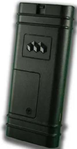
natural_image
Black rectangular electronic device with a small square button and a circular connector (no visible text or symbols)AR-3HU / VS-4LU

(Sold Separately)

OL-ADAPTER-B2G
This Adapter is supplied ONLY inside the Linkr LT boxes.

natural_image
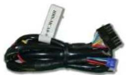
Close-up of a black electrical cable with various wires and connectors, no visible text or symbols on the main subject.HRN-MCAR-01
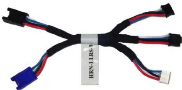
natural_image
Coiled black and red electrical connectors with blue and white connectors, labeled 'HRN-LLRS-9' (no other text or symbols)HRN-LLRS-01

natural_image
Coiled black cable with red and blue wires, labeled 'HRN-DRS-02' at bottom (no other text or symbols)PARTS REQUIRED FOR INSTALLATION OF : iDATASTART HCx
Telematics device HRN
MCAR-01 iDatastart HCx
natural_image
Coiled black cable with various connectors and wires, no visible text or symbols
natural_image
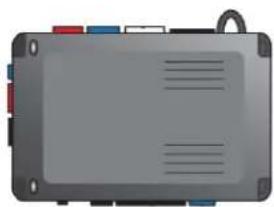
Illustration of a gray electronic device with red, blue, and white connectors (no text or symbols)STEP 1. CONFIGURE THE REMOTE STARTER
The ADS Weblink (ADS-USB) is required to properly configure the iDatastart HCx remote starter to accept the telematic device. When flashing the iDatastart HCx remote starter, please ensure to turn ON the Telematics option from the telematics section and choose "MyCar".
STEP 2. CONNECT

flowchart
graph TD
    A["3"] --> B["(+) 12V BATTERY^(1)"]
    A --> C["GROUND^(1)"]
    A --> D["(+) HORN (PULSE) OR (+) SIREN (CONSTANT) ANALOG INPUT SIGNAL FOR ALARM DETECTION"]
    B --> E["Data (WHITE)"]
    C --> E
    D --> E
    E --> F["Data (BLUE)"]
    E --> G["Alarm(+)(YELLOW)+12V Battery(RED)"]
    E --> H["Ground(BLACK)"]
    F --> I["Blue TELEMATICS PORT"]
    G --> I
    H --> I
    I --> J["Blue TELEMATICS PORT"]
    style A fill:#f9f,stroke:#333
    style J fill:#ccf,stroke:#333
(1) Connect only when remote starter is not supplying power to telematics device
CAR:LINK™
INSTALLATION, WIRING & PROGRAMMING GUIDE
STEP 3. NETWORK CONNECTIVITY
Once the telematics module is connected into the remote starter, two LED's will display to which networks you are connected to. (See LED Status Reference Chart on last page for details). NOTE: The vehicle may need to be outside in an open area in order to connect to a cellular and/or GPS network.
STEP 4. ADD A DEVICE/VEHICLE TO AN ACCOUNT
a. Click the “+” sign at the bottom right of the Application screen. This will allow you to temporarily add your customers device/vehicle to your personal account.
b. Enter the 16 digit "Serial Number" found at the back of the telematic device (SN: XXXXXX-XXXXXXXXXX) and Click "Submit the code".
c. You are now in "Test Mode". Test Mode will allow you up to 4 hours for you to test the newly installed device. At any time during this 4 hour period, you can exit testing mode and make unit "Ready for Customer Delivery" by "Releasing the vehicle" or by "Transferring the vehicle" from your account.
NOTE: If you do NOT remove the vehicle from your account, it will automatically be removed from your account and make the unit "Ready for Customer Delivery".
STEP 5. PRE-CONFIGURE MYCAR APPLICATION EXPERIENCE FOR YOUR CUSTOMER
a. Click on the newly added vehicle from the vehicle list to enter the control screen (the screen that will allow you to control the vehicle's remote start functions). This will automatically take you to the "Vehicle Configuration" page for this vehicle. You will be prompt to "Set a Bypass Protocol" to use this device. Click "Ok".
b. Now you must set the protocol for the telematic device. When combined with the iDatastart HCx remote starter previously installed, you must set the protocol to "ADS" and click "ACCEPT" then click "Done" at the top right corner.
c. Now please allow a moment (About 5 minutes) for the telematic device to update your protocol selection and reboot. After this wait period it will be available to accept commands from the App. In the vehicle control screen, the Device Signal icon located above the Stop button will display the connectivity status of your telematic device. If the icon is Grayed out, Please wait, Device is still Offline. If icon is Green, Device is Online and Ready to go.
d. Then from the top right click on of the Settings section edit the Vehicle name, configure the Auxiliaries that might have been added if applicable and click ACCEPT when done. Then choose the vehicle to display inside the control panel in the VEHICLE IMAGE section and click ACCEPT once done.
e. When your configurations are all completed, click "Done" at the top right corner. All Configurations will take effect.
STEP 6. TEST YOUR DEVICE
When the system is Online you start testing the unit from the vehicle control panel. Test all the application functions (Start, Stop, Lock, Unlock, Auxiliaries, ETC.) When done with the testing, from the vehicle list you can “Release” the vehicle. There are 2x different method to release it to the new owner. Choosing “release” will simply remove it from your account and make it “Ready for Customer Delivery”. Choosing “transfer” will transfer the device to the new owner’s account.
Also make sure that the Owners Card is handed to the New Owner of the vehicle. Doing this will ensure that the instructions on how to setup their App, Account and Vehicle is done correctly by using the device serial number located on the sticker affixed by the installer at the time of installation.
PARTS REQUIRED FOR INSTALLATION OF : iDATASTART VWx
Telematics device HRN-MCAR-01 iDatastart VWx


natural_image
Front view of a gray electronic device with multiple colored buttons and ventilation slots (no visible text or symbols)STEP 1. CONFIGURE THE REMOTE STARTER
The ADS Weblink (ADS-USB) is required to properly configure the iDatastart VWx remote starter to accept the telematic device. When flashing the iDatastart VWx remote starter, please ensure to turn ON the Telematics option from the telematics section and choose "MyCar".
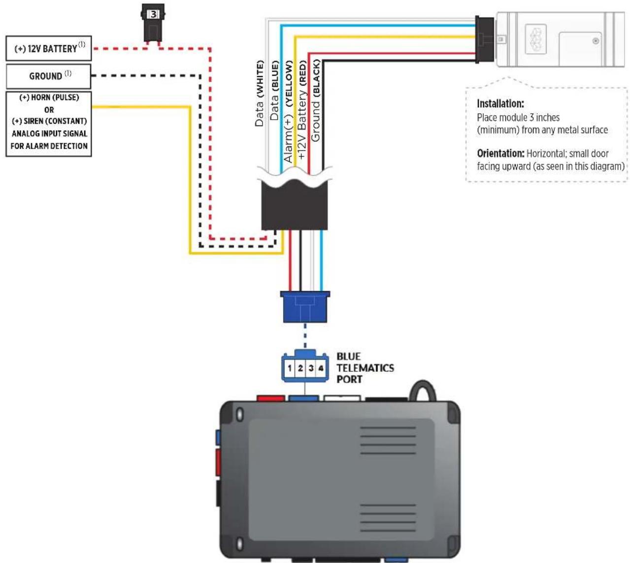
STEP 2. CONNECT
flowchart
graph TD
    A["3"] --> B["(+) 12V BATTERY^(1)"]
    A --> C["GROUND^(1)"]
    A --> D["(+) HORN (PULSE) OR (+) SIREN (CONSTANT) ANALOG INPUT SIGNAL FOR ALARM DETECTION"]
    B --> E["Data (WHITE)"]
    C --> E
    D --> E
    E --> F["Blue TELEMATICS PORT"]
    F --> G["1 2 3 4"]
    style A fill:#f9f,stroke:#333
    style G fill:#bbf,stroke:#333
(1) Connect only when remote starter is not supplying power to telematics device
CAR:LINK™
INSTALLATION, WIRING & PROGRAMMING GUIDE
STEP 3. NETWORK CONNECTIVITY
Once the telematics module is connected into the remote starter, two LED's will display to which networks you are connected to. (See LED Status Reference Chart on last page for details). NOTE: The vehicle may need to be outside in an open area in order to connect to a cellular and/or GPS network.
STEP 4. ADD A DEVICE/VEHICLE TO AN ACCOUNT
a. Click the “+” sign at the bottom right of the Application screen. This will allow you to temporarily add your customers device/vehicle to your personal account.
b. Enter the 16 digit "Serial Number" found at the back of the telematic device (SN: XXXXXX-XXXXXXXXXX) and Click "Submit the code".
c. You are now in "Test Mode". Test Mode will allow you up to 4 hours for you to test the newly installed device. At any time during this 4 hour period, you can exit testing mode and make unit "Ready for Customer Delivery" by "Releasing the vehicle" or by "Transferring the vehicle" from your account.
NOTE: If you do NOT remove the vehicle from your account, it will automatically be removed from your account and make the unit "Ready for Customer Delivery".
STEP 5. PRE-CONFIGURE MYCAR APPLICATION EXPERIENCE FOR YOUR CUSTOMER
a. Click on the newly added vehicle from the vehicle list to enter the control screen (the screen that will allow you to control the vehicle's remote start functions). This will automatically take you to the "Vehicle Configuration" page for this vehicle. You will be prompt to "Set a Bypass Protocol" to use this device. Click "Ok".
b. Now you must set the protocol for the telematic device. When combined with the iDatastart VW remote starter previously installed, you must set the protocol to "ADS" and click "ACCEPT" then click "Done" at the top right corner.
c. Now please allow a moment (About 5 minutes) for the telematic device to update your protocol selection and reboot. After this wait period it will be available to accept commands from the App. In the vehicle control screen, the Device Signal icon located above the Stop button will display the connectivity status of your telematic device. If the icon is Grayed out, Please wait, Device is still Offline. If icon is Green, Device is Online and Ready to go.
d. Then from the top right click on of the Settings section edit the Vehicle name, configure the Auxiliaries that might have been added if applicable and click ACCEPT when done. Then choose the vehicle to display inside the control panel in the VEHICLE IMAGE section and click ACCEPT once done.
e. When your configurations are all completed, click "Done" at the top right corner. All Configurations will take effect.
STEP 6. TEST YOUR DEVICE
When the system is Online you start testing the unit from the vehicle control panel. Test all the application functions (Start, Stop, Lock, Unlock, Auxiliaries, ETC.) When done with the testing, from the vehicle list you can “Release” the vehicle. There are 2x different method to release it to the new owner. Choosing “release” will simply remove it from your account and make it “Ready for Customer Delivery”. Choosing “transfer” will transfer the device to the new owner’s account.
Also make sure that the Owners Card is handed to the New Owner of the vehicle. Doing this will ensure that the instructions on how to setup their App, Account and Vehicle is done correctly by using the device serial number located on the sticker affixed by the installer at the time of installation.
PARTS REQUIRED FOR INSTALLATION OF : iDATASTART BM or BZ
Telematics device HRN-MCAR-01 iDatastart BM or BZ


natural_image
Top-down schematic of a device layout with no visible text or symbolsSTEP 1. CONFIGURE THE REMOTE STARTER
The ADS Weblink (ADS-USB) is required to properly configure the iDatastart BM or BZ remote starter to accept the telematic device. When flashing the iDatastart BM or BZ remote starter, please ensure to choose the "MyCar" telematics protocol.
STEP 2. CONNECT

flowchart
graph TD
    A[" (+) 12V BATTERY (1)"] -->|Ground (1)| B[" (+) HORN (PULSE) OR (+) SIREN (CONSTANT) ANALOG INPUT SIGNAL FOR ALARM DETECTION"]
    B --> C[" Data (WHITE) "]
    C --> D[" Data (BLUE)"]
    D --> E[" +12V Battery (RED) "]
    E --> F[" Ground (BLACK)"]
    F --> G[" Blue TELEMATICS PORT "]
    G --> H[" 1 2 3 4 "]
    I[" Installation: Place module 3 inches (minimum) from any metal surface"] --> J[" Orientation: Horizontal; small door facing upward (as seen in this diagram) "]
CAR:LINK™
INSTALLATION, WIRING & PROGRAMMING GUIDE
STEP 3. NETWORK CONNECTIVITY
Once the telematics module is connected into the remote starter, two LED's will display to which networks you are connected to. (See LED Status Reference Chart on last page for details). NOTE: The vehicle may need to be outside in an open area in order to connect to a cellular and/or GPS network.
STEP 4. ADD A DEVICE/VEHICLE TO AN ACCOUNT
a. Click the “+” sign at the bottom right of the Application screen. This will allow you to temporarily add your customers device/vehicle to your personal account.
b. Enter the 16 digit "Serial Number" found at the back of the telematic device (SN: XXXXXX-XXXXXXXXXX) and Click "Submit the code".
c. You are now in "Test Mode". Test Mode will allow you up to 4 hours for you to test the newly installed device. At any time during this 4 hour period, you can exit testing mode and make unit "Ready for Customer Delivery" by "Releasing the vehicle" or by "Transferring the vehicle" from your account.
NOTE: If you do NOT remove the vehicle from your account, it will automatically be removed from your account and make the unit "Ready for Customer Delivery".
STEP 5. PRE-CONFIGURE MYCAR APPLICATION EXPERIENCE FOR YOUR CUSTOMER
a. Click on the newly added vehicle from the vehicle list to enter the control screen (the screen that will allow you to control the vehicle's remote start functions). This will automatically take you to the "Vehicle Configuration" page for this vehicle. You will be prompt to "Set a Bypass Protocol" to use this device. Click "Ok".
b. Now you must set the protocol for the telematic device. When combined with the iDatastart BM or BZ remote starter previously installed, you must set the protocol to "ADS" and click "ACCEPT" then click "Done" at the top right corner.
c. Now please allow a moment (About 5 minutes) for the telematic device to update your protocol selection and reboot. After this wait period it will be available to accept commands from the App. In the vehicle control screen, the Device Signal icon located above the Stop button will display the connectivity status of your telematic device. If the icon is Grayed out, Please wait, Device is still Offline. If icon is Green, Device is Online and Ready to go.
d. Then from the top right click on of the Settings section edit the Vehicle name, configure the Auxiliaries that might have been added if applicable and click ACCEPT when done. Then choose the vehicle to display inside the control panel in the VEHICLE IMAGE section and click ACCEPT once done.
e. When your configurations are all completed, click "Done" at the top right corner. All Configurations will take effect.
STEP 6. TEST YOUR DEVICE
When the system is Online you start testing the unit from the vehicle control panel. Test all the application functions (Start, Stop, Lock, Unlock, Auxiliaries, ETC.) When done with the testing, from the vehicle list you can “Release” the vehicle. There are 2x different method to release it to the new owner. Choosing “release” will simply remove it from your account and make it “Ready for Customer Delivery”. Choosing “transfer” will transfer the device to the new owner’s account.
Also make sure that the Owners Card is handed to the New Owner of the vehicle. Doing this will ensure that the instructions on how to setup their App, Account and Vehicle is done correctly by using the device serial number located on the sticker affixed by the installer at the time of installation.
PARTS REQUIRED FOR INSTALLATION OF : AKX or OEM
Telematics device HRN-MCAR-01 AKX or OEM

STEP 1. CONFIGURE THE REMOTE STARTER
The ADS Weblink (ADS-USB) is required to properly configure the AKX or OEM remote starter to accept the telematic device. When flashing the AKX or OEM remote starter, please ensure to choose the "MyCar" telematics protocol.
STEP 2. CONNECT

flowchart
graph TD
    A[" (+) 12V BATTERY (1) "] --> B[" Ground (1) "]
    A --> C[" (+) HORN (PULSE) OR (+) SIREN (CONSTANT) ANALOG INPUT SIGNAL FOR ALARM DETECTION "]
    B --> D[" Data (WHITE) "]
    C --> D
    D --> E[" Data (BLUE) "]
    D --> F[" Alarm(+) (YELLOW) +12V Battery (RED) "]
    D --> G[" Ground (BLACK) "]
    E --> H[" Blue TELEMATICS PORT 1 2 3 4 "]
    F --> H
    G --> H
    style A fill:#f9f,stroke:#333
    style H fill:#bbf,stroke:#333
(1) Connect only when remote starter is not supplying power to telematics device
CAR:LINK™
INSTALLATION, WIRING & PROGRAMMING GUIDE
STEP 3. NETWORK CONNECTIVITY
Once the telematics module is connected into the remote starter, two LED's will display to which networks you are connected to. (See LED Status Reference Chart on last page for details). NOTE: The vehicle may need to be outside in an open area in order to connect to a cellular and/or GPS network.
STEP 4. ADD A DEVICE/VEHICLE TO AN ACCOUNT
a. Click the “+” sign at the bottom right of the Application screen. This will allow you to temporarily add your customers device/vehicle to your personal account.
b. Enter the 16 digit "Serial Number" found at the back of the telematic device (SN: XXXXXX-XXXXXXXXXX) and Click "Submit the code".
c. You are now in "Test Mode". Test Mode will allow you up to 4 hours for you to test the newly installed device. At any time during this 4 hour period, you can exit testing mode and make unit "Ready for Customer Delivery" by "Releasing the vehicle" or by "Transferring the vehicle" from your account.
NOTE: If you do NOT remove the vehicle from your account, it will automatically be removed from your account and make the unit "Ready for Customer Delivery".
STEP 5. PRE-CONFIGURE MYCAR APPLICATION EXPERIENCE FOR YOUR CUSTOMER
a. Click on the newly added vehicle from the vehicle list to enter the control screen (the screen that will allow you to control the vehicle's remote start functions). This will automatically take you to the "Vehicle Configuration" page for this vehicle. You will be prompt to "Set a Bypass Protocol" to use this device. Click "Ok".
b. Now you must set the protocol for the telematic device. When combined with the AKX or OEM remote starter previously installed, you must set the protocol to "ADS" and click "ACCEPT" then click "Done" at the top right corner.
c. Now please allow a moment (About 5 minutes) for the telematic device to update your protocol selection and reboot. After this wait period it will be available to accept commands from the App. In the vehicle control screen, the Device Signal icon located above the Stop button will display the connectivity status of your telematic device. If the icon is Grayed out, Please wait, Device is still Offline. If icon is Green, Device is Online and Ready to go.
d. Then from the top right click on of the Settings section edit the Vehicle name, configure the Auxiliaries that might have been added if applicable and click ACCEPT when done. Then choose the vehicle to display inside the control panel in the VEHICLE IMAGE section and click ACCEPT once done.
e. When your configurations are all completed, click "Done" at the top right corner. All Configurations will take effect.
STEP 6. TEST YOUR DEVICE
When the system is Online you start testing the unit from the vehicle control panel. Test all the application functions (Start, Stop, Lock, Unlock, Auxiliaries, ETC.) When done with the testing, from the vehicle list you can “Release” the vehicle. There are 2x different method to release it to the new owner. Choosing “release” will simply remove it from your account and make it “Ready for Customer Delivery”. Choosing “transfer” will transfer the device to the new owner’s account.
Also make sure that the Owners Card is handed to the New Owner of the vehicle. Doing this will ensure that the instructions on how to setup their App, Account and Vehicle is done correctly by using the device serial number located on the sticker affixed by the installer at the time of installation.
PARTS REQUIRED FOR INSTALLATION OF : ADS-AL-CA / OL-MDB-ALL
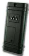
Telematics device HRN-MCAR-01

natural_image
Coiled black cable with various connectors and wires, no visible text or symbolsADS-AL-CA / OL-MDB-ALL

natural_image
Simple illustration of a gray rectangular device with three side slots and a blue top (no text or symbols)FLCL6HAR, OL-HRN-LINKR-ALL

(sold Separately)
STEP 1. CONFIGURE THE REMOTE STARTER
The ADS Weblink (ADS-USB) is required to properly configure the ADS-AL-CA or OL-MDB-ALL remote starter to accept the MyCar telematics device. When flashing the ADS-AL-CA or OL-MDB-ALL remote starter, please ensure to choose the "MyCar" telematics protocol.
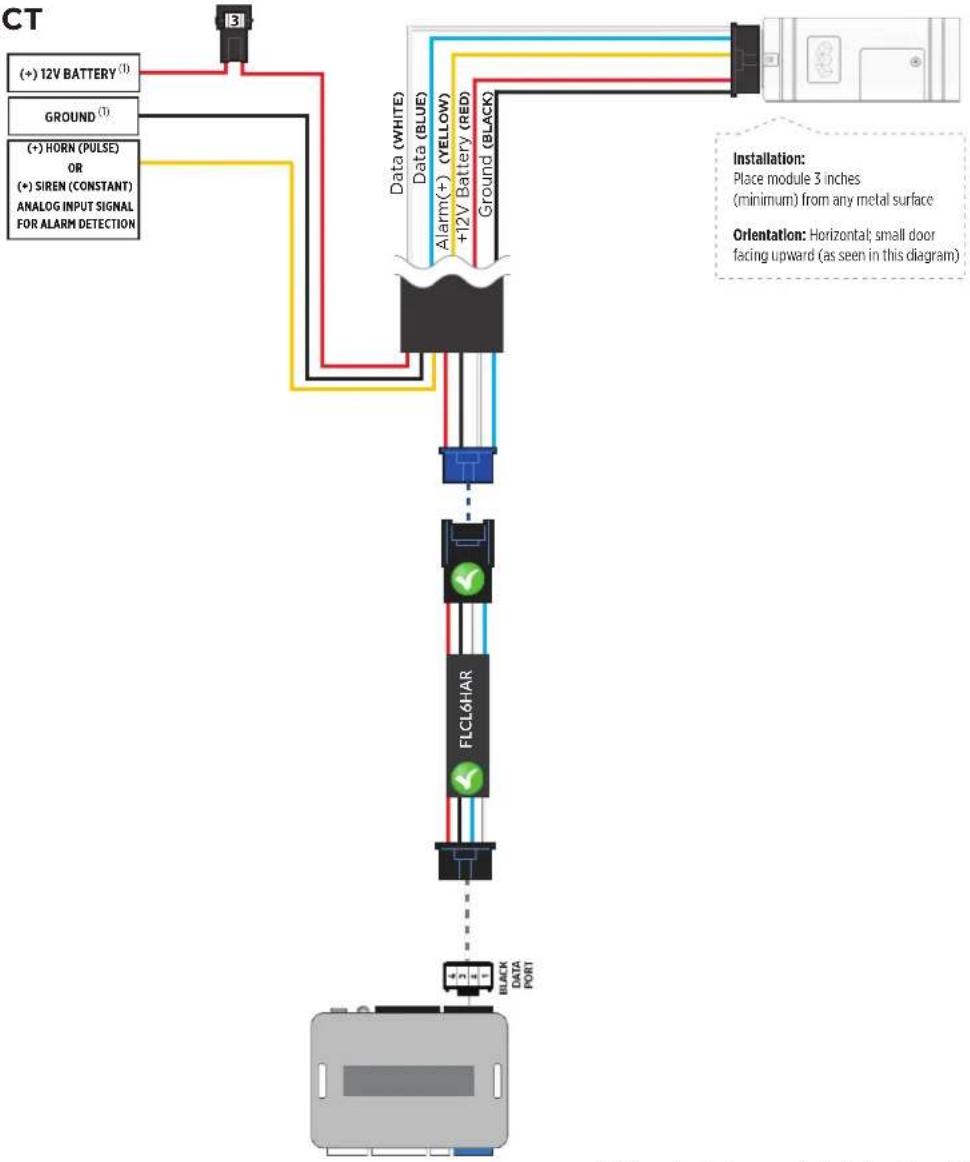
STEP 2. CONNECT
flowchart
graph TD
    A["CT"] --> B["+ 12V BATTERY (1)"]
    A --> C["GROUND (1)"]
    A --> D["+ HORN (PULSE) OR (+) SIREN (CONSTANT) ANALOG INPUT SIGNAL FOR ALARM DETECTION"]
    B --> E["Data (WHITE)"]
    C --> F["Data (BLUE)"]
    D --> G["Ground (BLACK)"]
    E --> H["FLCL6HAR"]
    F --> H
    G --> H
    H --> I["Black DATA PORT"]
    style A fill:#f9f,stroke:#333
    style I fill:#ccf,stroke:#333
(1) Connect only when remote starter is not supplying power to telematics device
CAR:LINK™
INSTALLATION, WIRING & PROGRAMMING GUIDE
STEP 3. NETWORK CONNECTIVITY
Once the telematics module is connected into the remote starter, two LED's will display to which networks you are connected to. (See LED Status Reference Chart on last page for details). NOTE: The vehicle may need to be outside in an open area in order to connect to a cellular and/or GPS network.
STEP 4. ADD A DEVICE/VEHICLE TO AN ACCOUNT
a. Click the “+” sign at the bottom right of the Application screen. This will allow you to temporarily add your customers device/vehicle to your personal account.
b. Enter the 16 digit "Serial Number" found at the back of the device (SN: XXXXXX-XXXXXXXXXX) and Click "Submit the code".
c. You are now in "Test Mode". Test Mode will allow you up to 4 hours for you to test the newly installed device. At any time during this 4 hour period, you can exit testing mode and make unit "Ready for Customer Delivery" by "Releasing the vehicle" or by "Transferring the vehicle" from your account.
NOTE: If you do NOT remove the vehicle from your account, it will automatically be removed from your account and make the unit "Ready for Customer Delivery".
STEP 5. PRE-CONFIGURE MYCAR APPLICATION EXPERIENCE FOR YOUR CUSTOMER
a. Click on the newly added vehicle from the vehicle list to enter the control screen (the screen that will allow you to control the vehicle's remote start functions). This will automatically take you to the "Vehicle Configuration" page for this vehicle. You will be prompt to "Set a Bypass Protocol" to use this device. Click "Ok".
b. Now you must set the protocol for the MyCar device. When combined with the ADS-AL-CA or OL-MDB-ALL remote starter previously installed, you must set the protocol to "ADS" and click "ACCEPT" then click "Done" at the top right corner.
c. Now please allow a moment (About 5 minutes) for the MyCar device to update your protocol selection and reboot. After this wait period it will be available to accept commands from the App. In the vehicle control screen, the Device Signal icon located above the Stop button will display the connectivity status of your MyCar device. If the icon is Grayed out, Please wait, Device is still Offline. If icon is Green, Device is Online and Ready to go.
d. Then from the top right click on of the Settings section edit the Vehicle name, configure the Auxiliaries that might have been added if applicable and click ACCEPT when done. Then choose the vehicle to display in the control panel in the VEHICLE IMAGE section and click ACCEPT once done.
e. When your configurations are all completed, click "Done" at the top right corner. All Configurations will take effect.
STEP 6. TEST YOUR DEVICE
When the system is Online you start testing the unit from the vehicle control panel. Test all the application functions (Start, Stop, Lock, Unlock, Auxiliaries, ETC.) When done with the testing, from the vehicle list you can “Release” the vehicle. There are 2x different method to release it to the new owner. Choosing “release” will simply remove it from your account and make it “Ready for Customer Delivery”. Choosing “transfer” will transfer the device to the new owner’s account.
Also make sure that the MyCar Owners Card is handed to the New Owner of the vehicle. Doing this will ensure that the instructions on how to setup their App, Account and Vehicle is done correctly by using the device serial number located on the sticker affixed by the installer at the time of installation.
PARTS REQUIRED FOR INSTALLATION OF : FLASHLOGIC FL-CAN
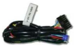
Telematics device HRN-MCAR-01

natural_image
Coiled black cable with various connectors and wires, no visible text or symbolsFlashlogic FL-CAN
natural_image
Simple illustration of a gray rectangular device with three side slots and a blue top (no text or symbols)FLCL6HAR
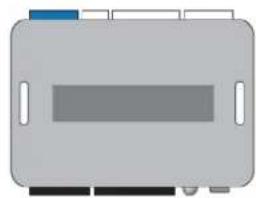
(sold Separately)
STEP 1. CONFIGURE THE REMOTE STARTER
The ADS Weblink (ADS-USB) is required to properly configure the Flashlogic FL-CAN remote starter to accept the MyCar telematics device. When flashing the Flashlogic FL-CAN remote starter, please ensure to choose the "ASCL6" telematics protocol.
STEP 2. CONNECT
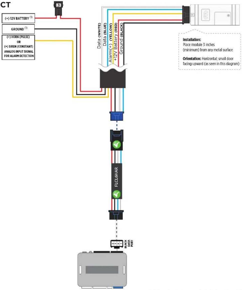
flowchart
graph TD
    A["CT"] --> B["+ 12V BATTERY (1)"]
    A --> C["GROUND (1)"]
    A --> D["+ HORN (PULSE) OR (+) SIREN (CONSTANT) ANALOG INPUT SIGNAL FOR ALARM DETECTION"]
    B --> E["Data (WHITE)"]
    C --> F["Data (BLUE)"]
    D --> G["Ground (BLACK)"]
    E --> H["FLCL6HAR"]
    F --> H
    G --> H
    H --> I["Black DATA PORT"]
    style A fill:#f9f,stroke:#333
    style I fill:#ccf,stroke:#333
    note right of H: FLCL6HAR
    note left of H: Black Data Port
    note right of H: Place module 3 inches (minimum) from any metal surface
    note right of H: Horizontal; small door facing upward (as seen in this diagram)
    note right of H: Orientation: Horizontal; small door facing upward (as seen in this diagram)
(1) Connect only when remote starter is not supplying power to telematics device
CAR:LINK™
INSTALLATION, WIRING & PROGRAMMING GUIDE
STEP 3. NETWORK CONNECTIVITY
Once the telematics module is connected into the remote starter, two LED's will display to which networks you are connected to. (See LED Status Reference Chart on last page for details). NOTE: The vehicle may need to be outside in an open area in order to connect to a cellular and/or GPS network.
STEP 4. ADD A DEVICE/VEHICLE TO AN ACCOUNT
a. Click the “+” sign at the bottom right of the Application screen. This will allow you to temporarily add your customers device/vehicle to your personal account.
b. Enter the 16 digit "Serial Number" found at the back of the device (SN: XXXXXX-XXXXXXXXXX) and Click "Submit the code".
c. You are now in "Test Mode". Test Mode will allow you up to 4 hours for you to test the newly installed device. At any time during this 4 hour period, you can exit testing mode and make unit "Ready for Customer Delivery" by "Releasing the vehicle" or by "Transferring the vehicle" from your account.
NOTE: If you do NOT remove the vehicle from your account, it will automatically be removed from your account and make the unit "Ready for Customer Delivery".
STEP 5. PRE-CONFIGURE MYCAR APPLICATION EXPERIENCE FOR YOUR CUSTOMER
a. Click on the newly added vehicle from the vehicle list to enter the control screen (the screen that will allow you to control the vehicle's remote start functions). This will automatically take you to the "Vehicle Configuration" page for this vehicle. You will be prompt to "Set a Bypass Protocol" to use this device. Click "Ok".
b. Now you must set the protocol for the MyCar device. When combined with the Flashlogic FL-CAN remote starter previously installed, you must set the protocol to "ADS" and click "ACCEPT" then click "Done" at the top right corner.
c. Now please allow a moment (About 5 minutes) for the MyCar device to update your protocol selection and reboot. After this wait period it will be available to accept commands from the App. In the vehicle control screen, the Device Signal icon located above the Stop button will display the connectivity status of your MyCar device. If the icon is Grayed out, Please wait, Device is still Offline. If icon is Green, Device is Online and Ready to go.
d. Then from the top right click on of the Settings section edit the Vehicle name, configure the Auxiliaries that might have been added if applicable and click ACCEPT when done. Then choose the vehicle to display in the control panel in the VEHICLE IMAGE section and click ACCEPT once done.
e. When your configurations are all completed, click "Done" at the top right corner. All Configurations will take effect.
STEP 6. TEST YOUR DEVICE
When the system is Online you start testing the unit from the vehicle control panel. Test all the application functions (Start, Stop, Lock, Unlock, Auxiliaries, ETC.) When done with the testing, from the vehicle list you can “Release” the vehicle. There are 2x different method to release it to the new owner. Choosing “release” will simply remove it from your account and make it “Ready for Customer Delivery”. Choosing “transfer” will transfer the device to the new owner’s account.
Also make sure that the MyCar Owners Card is handed to the New Owner of the vehicle. Doing this will ensure that the instructions on how to setup their App, Account and Vehicle is done correctly by using the device serial number located on the sticker affixed by the installer at the time of installation.
PARTS REQUIRED FOR INSTALLATION OF : CRIMESTOPPER
Telematics device HRN-MCAR-01 CrimeStopper HRN-LLRS-01


Compatible models: RS-00, RSx-G5, SP402, SP502
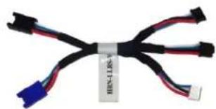
natural_image
Coiled black cable with red and blue connectors, no visible text or symbolsSTEP 1. CONFIGURE THE REMOTE STARTER
The CrimeStopper remote starter must be configured to accept the telematics device. When programming the CrimeStopper remote starter, please ensure to select the option indicated "Smart Phone Baud Rate". This option MUST BE SET TO 9600baud.
1- Disconnect the HRN-LLRS-01 white connector from Crimestopper Remote Starter
2- Go in the Crimestopper programming and set Baud rate to 9600.
3- Shut ignition Off and Disconnect Power from the Crimestopper RS.
5- Wait 10 seconds. Then Reconnect RS and the HRN-LLRS-01 harness for the MyCar.
STEP 2. CONNECT
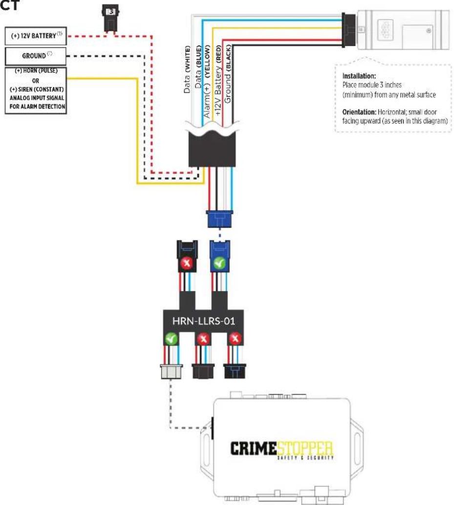
flowchart
graph TD
    A["181"] --> B["(+) 12V BATTERY"]
    A --> C["GROUND"]
    A --> D["(+) HORN (PULSE) OR (+) SIREN (CONSTANT) ANALOG INPUT SIGNAL FOR ALARM DETECTION"]
    B --> E["Data (WHITE)"]
    C --> E
    D --> E
    E --> F["HRN-LLRS-01"]
    F --> G["CRIME STOPPER SAFETY & SECURITY"]
    H["Data (BLUE)"] --> I["Alarm(+) (YELLOW) +12V Battery (RED) Ground (BLACK)"]
    I --> J["Installation: Place module 3 inches (minimum) from any metal surface"]
    I --> K["Orientation: Horizontal; small door facing upward (as seen in this diagram)"]
(1) Connect only when remote starter is not supplying power to telematics device
CAR:LINK™
INSTALLATION, WIRING & PROGRAMMING GUIDE
STEP 3. NETWORK CONNECTIVITY
Once the telematics module is connected into the remote starter, two LED's will display to which networks you are connected to. (See LED Status Reference Chart on last page for details). NOTE: The vehicle may need to be outside in an open area in order to connect to a cellular and/or GPS network.
STEP 4. ADD A DEVICE/VEHICLE TO AN ACCOUNT
a. Click the “+” sign at the bottom right of the Application screen. This will allow you to temporarily add your customers device/vehicle to your personal account.
b. Enter the 16 digit "Serial Number" found at the back of the telematic device (SN: XXXXXX-XXXXXXXXXX) and Click "Submit the code".
c. You are now in "Test Mode". Test Mode will allow you up to 4 hours for you to test the newly installed device. At any time during this 4 hour period, you can exit testing mode and make unit "Ready for Customer Delivery" by "Releasing the vehicle" or by "Transferring the vehicle" from your account.
NOTE: If you do NOT remove the vehicle from your account, it will automatically be removed from your account and make the unit "Ready for Customer Delivery".
STEP 5. PRE-CONFIGURE MYCAR APPLICATION EXPERIENCE FOR YOUR CUSTOMER
a. Click on the newly added vehicle from the vehicle list to enter the control screen (the screen that will allow you to control the vehicle's remote start functions). This will automatically take you to the "Vehicle Configuration" page for this vehicle. You will be prompt to "Set a Bypass Protocol" to use this device. Click "Ok".
b. Now you must set the protocol for the telematic device. When combined with the CrimeStopper remote starter previously installed, you must set the protocol to "ADS" and click "ACCEPT" then click "Done" at the top right corner.
c. Now please allow a moment (About 5 minutes) for the telematic device to update your protocol selection and reboot. After this wait period it will be available to accept commands from the App. In the vehicle control screen, the Device Signal icon located above the Stop button will display the connectivity status of your telematic device. If the icon is Grayed out, Please wait, Device is still Offline. If icon is Green, Device is Online and Ready to go.
d. Then from the top right click on of the Settings section edit the Vehicle name, configure the Auxiliaries that might have been added if applicable and click ACCEPT when done. Then choose the vehicle to display inside the control panel in the VEHICLE IMAGE section and click ACCEPT once done.
e. When your configurations are all completed, click "Done" at the top right corner. All Configurations will take effect.
STEP 6. TEST YOUR DEVICE
When the system is Online you start testing the unit from the vehicle control panel. Test all the application functions (Start, Stop, Lock, Unlock, Auxiliaries, ETC.) When done with the testing, from the vehicle list you can “Release” the vehicle. There are 2x different method to release it to the new owner. Choosing “release” will simply remove it from your account and make it “Ready for Customer Delivery”. Choosing “transfer” will transfer the device to the new owner’s account.
Also make sure that the Owners Card is handed to the New Owner of the vehicle. Doing this will ensure that the instructions on how to setup their App, Account and Vehicle is done correctly by using the device serial number located on the sticker affixed by the installer at the time of installation.
CRIMESTOPPER TROUBLESHOOTING
While testing the system, if you are unsuccessful at operating the Remote Starter using the telematic system it is probably related to the Baud rate not being set correctly as described in Step 1. To overcome this situation, please follow these steps.
1- Disconnect HRN-LLRS-01 white connector from Crimestopper Remote Starter.
2- Go in Crimestopper RS programming and set back the Baud rate to 115200.
3- Then inside the programming go to Reset all to default (following option right after the Baud Rate).
4- Shut ignition Off and Disconnect Power from the Crimestopper RS.
5- Wait 10 seconds. Then Reconnect Crimestopper RS only. DO NOT RECONNECT the telematics device yet.
6- Go back in the Crimestopper RS programming and set Baud rate to 9600.
7 - Shut ignition Off and Disconnect Power from the Crimestopper RS.
8- Wait 10 seconds. Then Reconnect Crimestopper RS and HRN-LLRS-01 harness for the telematic device.
9- Wait for the telematic device to be Online (Battery Status and Signal Green).
10- Send a Lock or Unlock command. Parking lights will click in the Crimestopper RS.
11- Then complete all other required programming in the Crimestopper RS.
PARTS REQUIRED FOR INSTALLATION OF : FLASHLOGIC FLRS
Telematics device HRN-MCAR-01 Flashlogic FLRS


natural_image
Simple diagram of a device casing with no text or symbolsSTEP 1. CONFIGURE THE REMOTE STARTER
The ADS Weblink (ADS-USB) is required to properly configure the Flashlogic FLRS remote starter to accept the telematic device. When flashing the Flashlogic FLRS remote starter, please ensure to choose the "ASCL6" telematics protocol.
STEP 2. CONNECT

flowchart
graph TD
    A[" (+) 12V BATTERY (1) "] --> B[" Ground (1) "]
    A --> C[" (+) HORN (PULSE) OR (+) SIREN (CONSTANT) ANALOG INPUT SIGNAL FOR ALARM DETECTION "]
    B --> D[" Data (WHITE) "]
    C --> D
    D --> E[" Data (BLUE) "]
    D --> F[" Alarm(+) (YELLOW) +12V Battery (RED) "]
    D --> G[" Ground (BLACK) "]
    E --> H[" Blue TELEMATICS PORT 1 2 3 4 "]
    F --> H
    G --> H
    style A fill:#f9f,stroke:#333
    style H fill:#bbf,stroke:#333
CAR:LINK™
INSTALLATION, WIRING & PROGRAMMING GUIDE
STEP 3. NETWORK CONNECTIVITY
Once the telematics module is connected into the remote starter, two LED's will display to which networks you are connected to. (See LED Status Reference Chart on last page for details). NOTE: The vehicle may need to be outside in an open area in order to connect to a cellular and/or GPS network.
STEP 4. ADD A DEVICE/VEHICLE TO AN ACCOUNT
a. Click the “+” sign at the bottom right of the Application screen. This will allow you to temporarily add your customers device/vehicle to your personal account.
b. Enter the 16 digit "Serial Number" found at the back of the telematic device (SN: XXXXXX-XXXXXXXXXX) and Click "Submit the code".
c. You are now in "Test Mode". Test Mode will allow you up to 4 hours for you to test the newly installed device. At any time during this 4 hour period, you can exit testing mode and make unit "Ready for Customer Delivery" by "Releasing the vehicle" or by "Transferring the vehicle" from your account.
NOTE: If you do NOT remove the vehicle from your account, it will automatically be removed from your account and make the unit "Ready for Customer Delivery".
STEP 5. PRE-CONFIGURE MYCAR APPLICATION EXPERIENCE FOR YOUR CUSTOMER
a. Click on the newly added vehicle from the vehicle list to enter the control screen (the screen that will allow you to control the vehicle's remote start functions). This will automatically take you to the "Vehicle Configuration" page for this vehicle. You will be prompt to "Set a Bypass Protocol" to use this device. Click "Ok".
b. Now you must set the protocol for the telematic device. When combined with the Flashlogic FLRS remote starter previously installed, you must set the protocol to "ADS" and click "ACCEPT" then click "Done" at the top right corner.
c. Now please allow a moment (About 5 minutes) for the telematic device to update your protocol selection and reboot. After this wait period it will be available to accept commands from the App. In the vehicle control screen, the Device Signal icon located above the Stop button will display the connectivity status of your telematic device. If the icon is Grayed out, Please wait, Device is still Offline. If icon is Green, Device is Online and Ready to go.
d. Then from the top right click on of the Settings section edit the Vehicle name, configure the Auxiliaries that might have been added if applicable and click ACCEPT when done. Then choose the vehicle to display inside the control panel in the VEHICLE IMAGE section and click ACCEPT once done.
e. When your configurations are all completed, click "Done" at the top right corner. All Configurations will take effect.
STEP 6. TEST YOUR DEVICE
When the system is Online you start testing the unit from the vehicle control panel. Test all the application functions (Start, Stop, Lock, Unlock, Auxiliaries, ETC.) When done with the testing, from the vehicle list you can “Release” the vehicle. There are 2x different method to release it to the new owner. Choosing “release” will simply remove it from your account and make it “Ready for Customer Delivery”. Choosing “transfer” will transfer the device to the new owner’s account.
Also make sure that the Owners Card is handed to the New Owner of the vehicle. Doing this will ensure that the instructions on how to setup their App, Account and Vehicle is done correctly by using the device serial number located on the sticker affixed by the installer at the time of installation.
PARTS REQUIRED FOR INSTALLATION OF : FLASHLOGIC FLRSBA
Telematics device HRN-MCAR-01 Flashlogic FLRSBA


natural_image
Top-down view of a gray electronic device casing with multiple colored buttons and mounting holes (no text or symbols visible)STEP 1. CONFIGURE THE REMOTE STARTER
The ADS Weblink (ADS-USB) is required to properly configure the Flashlogic FLRSBA remote starter to accept the telematic device. When flashing the Flashogic FLRSBA remote starter, please ensure to turn ON the Telematics option from the telematics section and choose "Carlink".
STEP 2. CONNECT

flowchart
graph TD
    A["3"] --> B["(+) 12V BATTERY¹"]
    A --> C["GROUND¹"]
    A --> D["(+) HORN (PULSE) OR (+) SIREN (CONSTANT) ANALOG INPUT SIGNAL FOR ALARM DETECTION"]
    B --> E["Data (WHITE)"]
    C --> F["Data (BLUE)"]
    D --> G["Ground (BLACK)"]
    E --> H["Blue TELEMATICS PORT"]
    F --> H
    G --> H
    H --> I["1 2 3 4"]
    style A fill:#f9f,stroke:#333
    style H fill:#ccf,stroke:#333
CAR:LINK™
INSTALLATION, WIRING & PROGRAMMING GUIDE
STEP 3. NETWORK CONNECTIVITY
Once the telematics module is connected into the remote starter, two LED's will display to which networks you are connected to. (See LED Status Reference Chart on last page for details). NOTE: The vehicle may need to be outside in an open area in order to connect to a cellular and/or GPS network.
STEP 4. ADD A DEVICE/VEHICLE TO AN ACCOUNT
a. Click the “+” sign at the bottom right of the Application screen. This will allow you to temporarily add your customers device/vehicle to your personal account.
b. Enter the 16 digit "Serial Number" found at the back of the telematic device (SN: XXXXXX-XXXXXXXXXX) and Click "Submit the code".
c. You are now in "Test Mode". Test Mode will allow you up to 4 hours for you to test the newly installed device. At any time during this 4 hour period, you can exit testing mode and make unit "Ready for Customer Delivery" by "Releasing the vehicle" or by "Transferring the vehicle" from your account.
NOTE: If you do NOT remove the vehicle from your account, it will automatically be removed from your account and make the unit "Ready for Customer Delivery".
STEP 5. PRE-CONFIGURE MYCAR APPLICATION EXPERIENCE FOR YOUR CUSTOMER
a. Click on the newly added vehicle from the vehicle list to enter the control screen (the screen that will allow you to control the vehicle's remote start functions). This will automatically take you to the "Vehicle Configuration" page for this vehicle. You will be prompt to "Set a Bypass Protocol" to use this device. Click "Ok".
b. Now you must set the protocol for the telematic device. When combined with the Flashlogic FLRSBA remote starter previously installed, you must set the protocol to "ADS" and click "ACCEPT" then click "Done" at the top right corner.
c. Now please allow a moment (About 5 minutes) for the telematic device to update your protocol selection and reboot. After this wait period it will be available to accept commands from the App. In the vehicle control screen, the Device Signal icon located above the Stop button will display the connectivity status of your telematic device. If the icon is Grayed out, Please wait, Device is still Offline. If icon is Green, Device is Online and Ready to go.
d. Then from the top right click on of the Settings section edit the Vehicle name, configure the Auxiliaries that might have been added if applicable and click ACCEPT when done. Then choose the vehicle to display inside the control panel in the VEHICLE IMAGE section and click ACCEPT once done.
e. When your configurations are all completed, click "Done" at the top right corner. All Configurations will take effect.
STEP 6. TEST YOUR DEVICE
When the system is Online you start testing the unit from the vehicle control panel. Test all the application functions (Start, Stop, Lock, Unlock, Auxiliaries, ETC.) When done with the testing, from the vehicle list you can “Release” the vehicle. There are 2x different method to release it to the new owner. Choosing “release” will simply remove it from your account and make it “Ready for Customer Delivery”. Choosing “transfer” will transfer the device to the new owner’s account.
Also make sure that the Owners Card is handed to the New Owner of the vehicle. Doing this will ensure that the instructions on how to setup their App, Account and Vehicle is done correctly by using the device serial number located on the sticker affixed by the installer at the time of installation.
PARTS REQUIRED FOR INSTALLATION OF : FLASHLOGIC FLCMVW
Telematics device HRN-MCAR-01 Flashlogic FLCMVW


natural_image
Front view of a gray electronic device casing with multiple colored buttons and mounting holes (no visible text or symbols)STEP 1. CONFIGURE THE REMOTE STARTER
The ADS Weblink (ADS-USB) is required to properly configure the Flashlogic FLCMVW remote starter to accept the telematic device. When flashing the Flashlogic FLCMVW remote starter, please ensure to turn ON the Telematics option from the telematics section and choose "Carlink".
STEP 2. CONNECT

flowchart
graph TD
    A["3"] --> B["(+) 12V BATTERY^(1)"]
    A --> C["GROUND^(1)"]
    A --> D["(+) HORN (PULSE) OR (+) SIREN (CONSTANT) ANALOG INPUT SIGNAL FOR ALARM DETECTION"]
    B --> E["Data (WHITE)"]
    C --> E
    D --> E
    E --> F["Blue TELEMATICS PORT"]
    F --> G["1 2 3 4"]
    style A fill:#f9f,stroke:#333
    style G fill:#bbf,stroke:#333
(1) Connect only when remote starter is not supplying power to telematics device
CAR:LINK™
INSTALLATION, WIRING & PROGRAMMING GUIDE
STEP 3. NETWORK CONNECTIVITY
Once the telematics module is connected into the remote starter, two LED's will display to which networks you are connected to. (See LED Status Reference Chart on last page for details). NOTE: The vehicle may need to be outside in an open area in order to connect to a cellular and/or GPS network.
STEP 4. ADD A DEVICE/VEHICLE TO AN ACCOUNT
a. Click the “+” sign at the bottom right of the Application screen. This will allow you to temporarily add your customers device/vehicle to your personal account.
b. Enter the 16 digit "Serial Number" found at the back of the telematic device (SN: XXXXXX-XXXXXXXXXX) and Click "Submit the code".
c. You are now in "Test Mode". Test Mode will allow you up to 4 hours for you to test the newly installed device. At any time during this 4 hour period, you can exit testing mode and make unit "Ready for Customer Delivery" by "Releasing the vehicle" or by "Transferring the vehicle" from your account.
NOTE: If you do NOT remove the vehicle from your account, it will automatically be removed from your account and make the unit "Ready for Customer Delivery".
STEP 5. PRE-CONFIGURE MYCAR APPLICATION EXPERIENCE FOR YOUR CUSTOMER
a. Click on the newly added vehicle from the vehicle list to enter the control screen (the screen that will allow you to control the vehicle's remote start functions). This will automatically take you to the "Vehicle Configuration" page for this vehicle. You will be prompt to "Set a Bypass Protocol" to use this device. Click "Ok".
b. Now you must set the protocol for the telematic device. When combined with the Flashlogic FLCMVW remote starter previously installed, you must set the protocol to "ADS" and click "ACCEPT" then click "Done" at the top right corner.
c. Now please allow a moment (About 5 minutes) for the telematic device to update your protocol selection and reboot. After this wait period it will be available to accept commands from the App. In the vehicle control screen, the Device Signal icon located above the Stop button will display the connectivity status of your telematic device. If the icon is Grayed out, Please wait, Device is still Offline. If icon is Green, Device is Online and Ready to go.
d. Then from the top right click on of the Settings section edit the Vehicle name, configure the Auxiliaries that might have been added if applicable and click ACCEPT when done. Then choose the vehicle to display inside the control panel in the VEHICLE IMAGE section and click ACCEPT once done.
e. When your configurations are all completed, click "Done" at the top right corner. All Configurations will take effect.
STEP 6. TEST YOUR DEVICE
When the system is Online you start testing the unit from the vehicle control panel. Test all the application functions (Start, Stop, Lock, Unlock, Auxiliaries, ETC.) When done with the testing, from the vehicle list you can “Release” the vehicle. There are 2x different method to release it to the new owner. Choosing “release” will simply remove it from your account and make it “Ready for Customer Delivery”. Choosing “transfer” will transfer the device to the new owner’s account.
Also make sure that the Owners Card is handed to the New Owner of the vehicle. Doing this will ensure that the instructions on how to setup their App, Account and Vehicle is done correctly by using the device serial number located on the sticker affixed by the installer at the time of installation.
PARTS REQUIRED FOR INSTALLATION OF : COMPUSTAR CM7000 / CM7200 / POLARSTART PRS-16
Telematics device HRN-MCAR-01


CM7000 / CM7200 / PRS-16

BLADE-AL (64)

STEP 1. CONFIGURE THE REMOTE STARTER
The ADS Weblink (ADS-USB) is required to properly configure the Compustar or Polarstart remote starter to accept the telematic device. When flashing the Compustar or Polarstart remote starter, please ensure the remote starter firmware and BLADE-AL (64) firmwares are updated to the latest firmware available.
Then set the Option Group #4 "DroneMobile or Fortin Gray 4pin" to DR-2000 and Flash remote starter.

flowchart
graph TD
    A["Step 2. CONNECT"] --> B["(+) 12V BATTERY¹"]
    A --> C["GROUND¹"]
    A --> D["(+) HORN (PULSE) OR (+) SIREN (CONSTANT) ANALOG INPUT SIGNAL FOR ALARM DETECTION"]
    B --> E["Data (WHITE)"]
    C --> F["Data (BLUE)"]
    D --> G["Alarm(+) (YELLOW) +12V Battery (RED)"]
    D --> H["Ground (BLACK)"]
    E --> I["Gray TELEMATICS PORT"]
    F --> I
    G --> I
    H --> I
    I --> J["BLADE-AL (64)"]
    I --> K["CNT200"]
CAR:LINK™
INSTALLATION, WIRING & PROGRAMMING GUIDE
STEP 3. NETWORK CONNECTIVITY
Once the telematics module is connected into the remote starter, two LED's will display to which networks you are connected to. (See LED Status Reference Chart on last page for details). NOTE: The vehicle may need to be outside in an open area in order to connect to a cellular and/or GPS network.
STEP 4. ADD A DEVICE/VEHICLE TO AN ACCOUNT
a. Click the “+” sign at the bottom right of the Application screen. This will allow you to temporarily add your customers device/vehicle to your personal account.
b. Enter the 16 digit "Serial Number" found at the back of the telematic device (SN: XXXXXX-XXXXXXXXXX) and Click "Submit the code".
c. You are now in "Test Mode". Test Mode will allow you up to 4 hours for you to test the newly installed device. At any time during this 4 hour period, you can exit testing mode and make unit "Ready for Customer Delivery" by "Releasing the vehicle" or by "Transferring the vehicle" from your account.
NOTE: If you do NOT remove the vehicle from your account, it will automatically be removed from your account and make the unit "Ready for Customer Delivery".
STEP 5. PRE-CONFIGURE MYCAR APPLICATION EXPERIENCE FOR YOUR CUSTOMER
a. Click on the newly added vehicle from the vehicle list to enter the control screen (the screen that will allow you to control the vehicle's remote start functions). This will automatically take you to the "Vehicle Configuration" page for this vehicle. You will be prompt to "Set a Bypass Protocol" to use this device. Click "Ok".
b. Now you must set the protocol for the telematic device. When combined with the Compustar or Polarstart remote starter previously installed, you must set the protocol to "ADS" and click "ACCEPT" then click "Done" at the top right corner.
c. Now please allow a moment (About 5 minutes) for the telematic device to update your protocol selection and reboot. After this wait period it will be available to accept commands from the App. In the vehicle control screen, the Device Signal icon located above the Stop button will display the connectivity status of your telematic device. If the icon is Grayed out, Please wait, Device is still Offline. If icon is Green, Device is Online and Ready to go.
d. Then from the top right click on of the Settings section edit the Vehicle name, configure the Auxiliaries that might have been added if applicable and click ACCEPT when done. Then choose the vehicle to display inside the control panel in the VEHICLE IMAGE section and click ACCEPT once done.
e. When your configurations are all completed, click "Done" at the top right corner. All Configurations will take effect.
STEP 6. TEST YOUR DEVICE
When the system is Online you start testing the unit from the vehicle control panel. Test all the application functions (Start, Stop, Lock, Unlock, Auxiliaries, ETC.) When done with the testing, from the vehicle list you can “Release” the vehicle. There are 2x different method to release it to the new owner. Choosing “release” will simply remove it from your account and make it “Ready for Customer Delivery”. Choosing “transfer” will transfer the device to the new owner’s account.
Also make sure that the Owners Card is handed to the New Owner of the vehicle. Doing this will ensure that the instructions on how to setup their App, Account and Vehicle is done correctly by using the device serial number located on the sticker affixed by the installer at the time of installation.
PARTS REQUIRED FOR INSTALLATION OF : COMPUSTAR CM6200
Telematics device HRN-MCAR-01 Compustar CM6200 BLADE-AL (64)


STEP 1. CONFIGURE THE REMOTE STARTER
The ADS Weblink (ADS-USB) is required to properly configure the Compustar remote starter to accept the telematic device. When flashing the Compustar remote starter, please ensure the remote starter firmware and BLADE-AL (64) firmwares are updated to the latest firmware available.
STEP 2. CONNECT

flowchart
graph TD
    A["BLADE-AL (64)"] -->|1 2 3 4| B["BLACK TELEMATICS PORT"]
    B --> C["Data (WHITE)"]
    C --> D["Ground (BLACK)"]
    D --> E["+12V Battery (RED)"]
    E --> F["Alarm (+) (YELLOW)"]
    F --> G["Data (BLUE)"]
    G --> H["+12V Battery (RED)"]
    H --> I["Ground (BLACK)"]
    I --> J["BLADE-AL (64)"]
    style A fill:#f9f,stroke:#333
    style B fill:#ccf,stroke:#333
    style C fill:#cfc,stroke:#333
    style D fill:#fcc,stroke:#333
    style E fill:#cff,stroke:#333
    style F fill:#ffc,stroke:#333
    style G fill:#fcc,stroke:#333
    style H fill:#ffc,stroke:#333
    style I fill:#fcc,stroke:#333
    style J fill:#ccf,stroke:#333
CAR:LINK™
INSTALLATION, WIRING & PROGRAMMING GUIDE
STEP 3. NETWORK CONNECTIVITY
Once the telematics module is connected into the remote starter, two LED's will display to which networks you are connected to. (See LED Status Reference Chart on last page for details). NOTE: The vehicle may need to be outside in an open area in order to connect to a cellular and/or GPS network.
STEP 4. ADD A DEVICE/VEHICLE TO AN ACCOUNT
a. Click the “+” sign at the bottom right of the Application screen. This will allow you to temporarily add your customers device/vehicle to your personal account.
b. Enter the 16 digit "Serial Number" found at the back of the telematic device (SN: XXXXXX-XXXXXXXXXX) and Click "Submit the code".
c. You are now in "Test Mode". Test Mode will allow you up to 4 hours for you to test the newly installed device. At any time during this 4 hour period, you can exit testing mode and make unit "Ready for Customer Delivery" by "Releasing the vehicle" or by "Transferring the vehicle" from your account.
NOTE: If you do NOT remove the vehicle from your account, it will automatically be removed from your account and make the unit "Ready for Customer Delivery".
STEP 5. PRE-CONFIGURE MYCAR APPLICATION EXPERIENCE FOR YOUR CUSTOMER
a. Click on the newly added vehicle from the vehicle list to enter the control screen (the screen that will allow you to control the vehicle's remote start functions). This will automatically take you to the "Vehicle Configuration" page for this vehicle. You will be prompt to "Set a Bypass Protocol" to use this device. Click "Ok".
b. Now you must set the protocol for the telematic device. When combined with the Compustar remote starter previously installed, you must set the protocol to "ADS" and click "ACCEPT" then click "Done" at the top right corner.
c. Now please allow a moment (About 5 minutes) for the telematic device to update your protocol selection and reboot. After this wait period it will be available to accept commands from the App. In the vehicle control screen, the Device Signal icon located above the Stop button will display the connectivity status of your telematic device. If the icon is Grayed out, Please wait, Device is still Offline. If icon is Green, Device is Online and Ready to go.
d. Then from the top right click on of the Settings section edit the Vehicle name, configure the Auxiliaries that might have been added if applicable and click ACCEPT when done. Then choose the vehicle to display inside the control panel in the VEHICLE IMAGE section and click ACCEPT once done.
e. When your configurations are all completed, click "Done" at the top right corner. All Configurations will take effect.
STEP 6. TEST YOUR DEVICE
When the system is Online you start testing the unit from the vehicle control panel. Test all the application functions (Start, Stop, Lock, Unlock, Auxiliaries, ETC.) When done with the testing, from the vehicle list you can “Release” the vehicle. There are 2x different method to release it to the new owner. Choosing “release” will simply remove it from your account and make it “Ready for Customer Delivery”. Choosing “transfer” will transfer the device to the new owner’s account.
Also make sure that the Owners Card is handed to the New Owner of the vehicle. Doing this will ensure that the instructions on how to setup their App, Account and Vehicle is done correctly by using the device serial number located on the sticker affixed by the installer at the time of installation.
PARTS REQUIRED FOR INSTALLATION OF : COMPUSTAR DC2
Telematics device HRN-MCAR-01 Compustar DC2


natural_image
3D rendering of a rectangular electronic component with mounting holes and internal compartments (no text or symbols)STEP 1. CONFIGURE THE REMOTE STARTER
The ADS Weblink (ADS-USB) is required to properly configure the Compustar DC2 remote starter to accept the telematic device. When flashing the Compustar DC2 remote starter, please ensure to turn ON the Telematics option from the telematics section and choose "Drone Mobile".
STEP 2. CONNECT

flowchart
graph TD
    A["Gray Telematics Port"] -->|1 2 3 4| B["Data (WHITE)"]
    B --> C["Ground (BLACK)"]
    C --> D["+12V Battery (RED)"]
    D --> E["Alarm(+) (YELLOW)"]
    E --> F["Data (BLUE)"]
    F --> G["Ground"]
    G --> H["Gray"]
    I["(+) 12V BATTERY^(1)"] -.-> J["Ground"]
    K["(+) HORN (PULSE) OR (+) SIREN (CONSTANT) ANALOG INPUT SIGNAL FOR ALARM DETECTION"] -.-> L["Ground"]
    M["Installation: Place module 3 inches (minimum) from any metal surface"] --> N["Orientation: Horizontal; small door facing upward (as seen in this diagram)"]
CAR:LINK™
INSTALLATION, WIRING & PROGRAMMING GUIDE
STEP 3. NETWORK CONNECTIVITY
Once the telematics module is connected into the remote starter, two LED's will display to which networks you are connected to. (See LED Status Reference Chart on last page for details). NOTE: The vehicle may need to be outside in an open area in order to connect to a cellular and/or GPS network.
STEP 4. ADD A DEVICE/VEHICLE TO AN ACCOUNT
a. Click the “+” sign at the bottom right of the Application screen. This will allow you to temporarily add your customers device/vehicle to your personal account.
b. Enter the 16 digit "Serial Number" found at the back of the telematic device (SN: XXXXXX-XXXXXXXXXX) and Click "Submit the code".
c. You are now in "Test Mode". Test Mode will allow you up to 4 hours for you to test the newly installed device. At any time during this 4 hour period, you can exit testing mode and make unit "Ready for Customer Delivery" by "Releasing the vehicle" or by "Transferring the vehicle" from your account.
NOTE: If you do NOT remove the vehicle from your account, it will automatically be removed from your account and make the unit "Ready for Customer Delivery".
STEP 5. PRE-CONFIGURE MYCAR APPLICATION EXPERIENCE FOR YOUR CUSTOMER
a. Click on the newly added vehicle from the vehicle list to enter the control screen (the screen that will allow you to control the vehicle's remote start functions). This will automatically take you to the "Vehicle Configuration" page for this vehicle. You will be prompt to "Set a Bypass Protocol" to use this device. Click "Ok".
b. Now you must set the protocol for the telematic device. When combined with the Compustar DC2 remote starter previously installed, you must set the protocol to "ADS" and click "ACCEPT" then click "Done" at the top right corner.
c. Now please allow a moment (About 5 minutes) for the telematic device to update your protocol selection and reboot. After this wait period it will be available to accept commands from the App. In the vehicle control screen, the Device Signal icon located above the Stop button will display the connectivity status of your telematic device. If the icon is Grayed out, Please wait, Device is still Offline. If icon is Green, Device is Online and Ready to go.
d. Then from the top right click on of the Settings section edit the Vehicle name, configure the Auxiliaries that might have been added if applicable and click ACCEPT when done. Then choose the vehicle to display inside the control panel in the VEHICLE IMAGE section and click ACCEPT once done.
e. When your configurations are all completed, click "Done" at the top right corner. All Configurations will take effect.
STEP 6. TEST YOUR DEVICE
When the system is Online you start testing the unit from the vehicle control panel. Test all the application functions (Start, Stop, Lock, Unlock, Auxiliaries, ETC.) When done with the testing, from the vehicle list you can “Release” the vehicle. There are 2x different method to release it to the new owner. Choosing “release” will simply remove it from your account and make it “Ready for Customer Delivery”. Choosing “transfer” will transfer the device to the new owner’s account.
Also make sure that the Owners Card is handed to the New Owner of the vehicle. Doing this will ensure that the instructions on how to setup their App, Account and Vehicle is done correctly by using the device serial number located on the sticker affixed by the installer at the time of installation.
PARTS REQUIRED FOR INSTALLATION OF : COMPUSTAR DC3
Telematics device HRN-MCAR-01 Compustar DC3


natural_image
3D rendering of a mechanical or electronic component with no visible text or symbolsSTEP 1. CONFIGURE THE REMOTE STARTER
The ADS Weblink (ADS-USB) is required to properly configure the Compustar DC3 remote starter to accept the telematic device. When flashing the Compustar DC3 remote starter, please ensure to turn ON the Telematics option from the telematics section and choose "Drone Mobile".
STEP 2. CONNECT

flowchart
graph TD
    A["3"] --> B["(+) 12V BATTERY^(1)"]
    A --> C["GROUND^(1)"]
    A --> D["(+) HORN (PULSE) OR (+) SIREN (CONSTANT) ANALOG INPUT SIGNAL FOR ALARM DETECTION"]
    B --> E["Data (WHITE)"]
    C --> E
    D --> E
    E --> F["Data (BLUE)"]
    E --> G["Alarm(+)(YELLOW)+12V Battery(RED)"]
    E --> H["Ground(BLACK)"]
    F --> I["Gray TELEMATICS PORT"]
    G --> I
    H --> I
    I --> J["Gray TELEMATICS PORT"]
    style A fill:#f9f,stroke:#333
    style J fill:#ccf,stroke:#333
CAR:LINK™
INSTALLATION, WIRING & PROGRAMMING GUIDE
STEP 3. NETWORK CONNECTIVITY
Once the telematics module is connected into the remote starter, two LED's will display to which networks you are connected to. (See LED Status Reference Chart on last page for details). NOTE: The vehicle may need to be outside in an open area in order to connect to a cellular and/or GPS network.
STEP 4. ADD A DEVICE/VEHICLE TO AN ACCOUNT
a. Click the “+” sign at the bottom right of the Application screen. This will allow you to temporarily add your customers device/vehicle to your personal account.
b. Enter the 16 digit "Serial Number" found at the back of the telematic device (SN: XXXXXX-XXXXXXXXXX) and Click "Submit the code".
c. You are now in "Test Mode". Test Mode will allow you up to 4 hours for you to test the newly installed device. At any time during this 4 hour period, you can exit testing mode and make unit "Ready for Customer Delivery" by "Releasing the vehicle" or by "Transferring the vehicle" from your account.
NOTE: If you do NOT remove the vehicle from your account, it will automatically be removed from your account and make the unit "Ready for Customer Delivery".
STEP 5. PRE-CONFIGURE MYCAR APPLICATION EXPERIENCE FOR YOUR CUSTOMER
a. Click on the newly added vehicle from the vehicle list to enter the control screen (the screen that will allow you to control the vehicle's remote start functions). This will automatically take you to the "Vehicle Configuration" page for this vehicle. You will be prompt to "Set a Bypass Protocol" to use this device. Click "Ok".
b. Now you must set the protocol for the telematic device. When combined with the Compustar DC3 remote starter previously installed, you must set the protocol to "ADS" and click "ACCEPT" then click "Done" at the top right corner.
c. Now please allow a moment (About 5 minutes) for the telematic device to update your protocol selection and reboot. After this wait period it will be available to accept commands from the App. In the vehicle control screen, the Device Signal icon located above the Stop button will display the connectivity status of your telematic device. If the icon is Grayed out, Please wait, Device is still Offline. If icon is Green, Device is Online and Ready to go.
d. Then from the top right click on of the Settings section edit the Vehicle name, configure the Auxiliaries that might have been added if applicable and click ACCEPT when done. Then choose the vehicle to display inside the control panel in the VEHICLE IMAGE section and click ACCEPT once done.
e. When your configurations are all completed, click "Done" at the top right corner. All Configurations will take effect.
STEP 6. TEST YOUR DEVICE
When the system is Online you start testing the unit from the vehicle control panel. Test all the application functions (Start, Stop, Lock, Unlock, Auxiliaries, ETC.) When done with the testing, from the vehicle list you can “Release” the vehicle. There are 2x different method to release it to the new owner. Choosing “release” will simply remove it from your account and make it “Ready for Customer Delivery”. Choosing “transfer” will transfer the device to the new owner’s account.
Also make sure that the Owners Card is handed to the New Owner of the vehicle. Doing this will ensure that the instructions on how to setup their App, Account and Vehicle is done correctly by using the device serial number located on the sticker affixed by the installer at the time of installation.
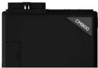
PARTS REQUIRED FOR INSTALLATION OF : POLARSTART PRS-13
Telematics device HRN-MCAR-01 PRS-13 BLADE-AL (64)


natural_image
Black electronic device casing with a gray triangular label reading 'CH900' on the side (no other text or symbols visible)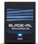
STEP 1. CONFIGURE THE REMOTE STARTER
The ADS Weblink (ADS-USB) is required to properly configure the Polarstart PRS-13 remote starter to accept the telematic device. When flashing the Polarstart PRS-13 remote starter, please ensure the remote starter firmware and BLADE-AL (64) firmwares are updated to the latest firmware available. Then ensure to set the Option Group #4 "DroneMobile or Fortin Gray 4pin" to DR-2000 and Flash remote starter.
STEP 2. CONNECT

flowchart
graph TD
    A["Ch900"] --> B["Gray Telematics Port"]
    B --> C["Data (WHITE)"]
    C --> D["Data (BLUE)"]
    C --> E["Alarm(+)(YELLOW)"]
    C --> F["Ground (BLACK)"]
    D --> G["+12V Battery (RED)"]
    E --> G
    F --> G
    G --> H["Display Module"]
    style A fill:#f9f,stroke:#333
    style B fill:#ccf,stroke:#333
    style C fill:#cfc,stroke:#333
    style D fill:#fcc,stroke:#333
    style E fill:#cff,stroke:#333
    style F fill:#ffc,stroke:#333
    style G fill:#fcf,stroke:#333
    note right of C: Place module 3 inches (minimum) from any metal surface; Orientation: Horizontal; small door facing upward (as seen in this diagram)
    note left of A: (+) 12V BATTERY (1)
    note right of D: Data (BLUE)
    note right of E: +12V Battery (RED)
    note right of F: Ground (BLACK)
CAR:LINK™
INSTALLATION, WIRING & PROGRAMMING GUIDE
STEP 3. NETWORK CONNECTIVITY
Once the telematics module is connected into the remote starter, two LED's will display to which networks you are connected to. (See LED Status Reference Chart on last page for details). NOTE: The vehicle may need to be outside in an open area in order to connect to a cellular and/or GPS network.
STEP 4. ADD A DEVICE/VEHICLE TO AN ACCOUNT
a. Click the “+” sign at the bottom right of the Application screen. This will allow you to temporarily add your customers device/vehicle to your personal account.
b. Enter the 16 digit "Serial Number" found at the back of the telematic device (SN: XXXXXX-XXXXXXXXXX) and Click "Submit the code".
c. You are now in "Test Mode". Test Mode will allow you up to 4 hours for you to test the newly installed device. At any time during this 4 hour period, you can exit testing mode and make unit "Ready for Customer Delivery" by "Releasing the vehicle" or by "Transferring the vehicle" from your account.
NOTE: If you do NOT remove the vehicle from your account, it will automatically be removed from your account and make the unit "Ready for Customer Delivery".
STEP 5. PRE-CONFIGURE MYCAR APPLICATION EXPERIENCE FOR YOUR CUSTOMER
a. Click on the newly added vehicle from the vehicle list to enter the control screen (the screen that will allow you to control the vehicle's remote start functions). This will automatically take you to the "Vehicle Configuration" page for this vehicle. You will be prompt to "Set a Bypass Protocol" to use this device. Click "Ok".
b. Now you must set the protocol for the telematic device. When combined with the Polarstart PRS-13 remote starter previously installed, you must set the protocol to "ADS" and click "ACCEPT" then click "Done" at the top right corner.
c. Now please allow a moment (About 5 minutes) for the telematic device to update your protocol selection and reboot. After this wait period it will be available to accept commands from the App. In the vehicle control screen, the Device Signal icon located above the Stop button will display the connectivity status of your telematic device. If the icon is Grayed out, Please wait, Device is still Offline. If icon is Green, Device is Online and Ready to go.
d. Then from the top right click on of the Settings section edit the Vehicle name, configure the Auxiliaries that might have been added if applicable and click ACCEPT when done. Then choose the vehicle to display inside the control panel in the VEHICLE IMAGE section and click ACCEPT once done.
e. When your configurations are all completed, click "Done" at the top right corner. All Configurations will take effect.
STEP 6. TEST YOUR DEVICE
When the system is Online you start testing the unit from the vehicle control panel. Test all the application functions (Start, Stop, Lock, Unlock, Auxiliaries, ETC.) When done with the testing, from the vehicle list you can “Release” the vehicle. There are 2x different method to release it to the new owner. Choosing “release” will simply remove it from your account and make it “Ready for Customer Delivery”. Choosing “transfer” will transfer the device to the new owner’s account.
Also make sure that the Owners Card is handed to the New Owner of the vehicle. Doing this will ensure that the instructions on how to setup their App, Account and Vehicle is done correctly by using the device serial number located on the sticker affixed by the installer at the time of installation.
PARTS REQUIRED FOR INSTALLATION OF : DIRECTED DBALL 2
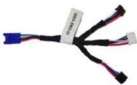
Telematics device HRN-MCAR-01 DBALL2 HRN-DRS-01 or


natural_image
Coiled black cable with various connectors and colored wires, no visible text or symbols
HRN-DRS-02
natural_image
Coiled black cable with blue and red connectors, no visible text or symbolsSTEP 1. CONFIGURE THE REMOTE STARTER
The Directed XKloader 2 or 3 is required to properly configure the DBALL2 remote starter to accept the telematic device. When flashing the DBALL2 remote starter, please ensure to choose the "Smartstart" telematic protocol.
STEP 2. CONNECT

flowchart
graph TD
    A["13"] --> B["Data (WHITE)"]
    A --> C["Data (BLUE)"]
    A --> D["Alarm(+) (YELLOW)"]
    A --> E["Ground (BLACK)"]
    B --> F["HRN-DRS-02"]
    C --> F
    D --> F
    E --> F
    F --> G["White DATA PORT 1 2 3 4"]
    G --> H["DBALL 2"]
    style A fill:#f9f,stroke:#333
    style H fill:#ccf,stroke:#333
(1) Connect only when remote starter is not supplying power to telematics device
CAR:LINK™
INSTALLATION, WIRING & PROGRAMMING GUIDE
STEP 3. NETWORK CONNECTIVITY
Once the telematics module is connected into the remote starter, two LED's will display to which networks you are connected to. (See LED Status Reference Chart on last page for details). NOTE: The vehicle may need to be outside in an open area in order to connect to a cellular and/or GPS network.
STEP 4. ADD A DEVICE/VEHICLE TO AN ACCOUNT
a. Click the “+” sign at the bottom right of the Application screen. This will allow you to temporarily add your customers device/vehicle to your personal account.
b. Enter the 16 digit "Serial Number" found at the back of the telematic device (SN: XXXXXX-XXXXXXXXXX) and Click "Submit the code".
c. You are now in "Test Mode". Test Mode will allow you up to 4 hours for you to test the newly installed device. At any time during this 4 hour period, you can exit testing mode and make unit "Ready for Customer Delivery" by "Releasing the vehicle" or by "Transferring the vehicle" from your account.
NOTE: If you do NOT remove the vehicle from your account, it will automatically be removed from your account and make the unit "Ready for Customer Delivery".
STEP 5. PRE-CONFIGURE MYCAR APPLICATION EXPERIENCE FOR YOUR CUSTOMER
a. Click on the newly added vehicle from the vehicle list to enter the control screen (the screen that will allow you to control the vehicle's remote start functions). This will automatically take you to the "Vehicle Configuration" page for this vehicle. You will be prompt to "Set a Bypass Protocol" to use this device. Click "Ok".
b. Now you must set the protocol for the telematic device. When combined with the DBALL2 remote starter previously installed, you must set the protocol to "DEI" and click "ACCEPT" then click "Done" at the top right corner.
c. Now please allow a moment (About 5 minutes) for the telematic device to update your protocol selection and reboot. After this wait period it will be available to accept commands from the App. In the vehicle control screen, the Device Signal icon located above the Stop button will display the connectivity status of your telematic device. If the icon is Grayed out, Please wait, Device is still Offline. If icon is Green, Device is Online and Ready to go.
d. Then from the top right click on of the Settings section edit the Vehicle name, configure the Auxiliaries that might have been added if applicable and click ACCEPT when done. Then choose the vehicle to display inside the control panel in the VEHICLE IMAGE section and click ACCEPT once done.
e. When your configurations are all completed, click "Done" at the top right corner. All Configurations will take effect.
STEP 6. TEST YOUR DEVICE
When the system is Online you start testing the unit from the vehicle control panel. Test all the application functions (Start, Stop, Lock, Unlock, Auxiliaries, ETC.) When done with the testing, from the vehicle list you can “Release” the vehicle. There are 2x different method to release it to the new owner. Choosing “release” will simply remove it from your account and make it “Ready for Customer Delivery”. Choosing “transfer” will transfer the device to the new owner’s account.
Also make sure that the Owners Card is handed to the New Owner of the vehicle. Doing this will ensure that the instructions on how to setup their App, Account and Vehicle is done correctly by using the device serial number located on the sticker affixed by the installer at the time of installation.
PARTS REQUIRED FOR INSTALLATION OF : DIRECTED DB3
Telematics device HRN-MCAR-01 DB3 HRN-DRS-01 or

natural_image
Coiled black cable with various connectors and wires, no visible text or symbols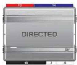
HRN-DRS-02

natural_image
Coiled black cable with blue and red wires, no visible text or symbolsSTEP 1. CONFIGURE THE REMOTE STARTER
The Directed XKloader 2 or 3 is required to properly configure the DB3 remote starter to accept the telematic device. When flashing the DB3 remote starter, please ensure to choose the "Smartstart" telematic protocol.
STEP 2. CONNECT

flowchart
graph TD
    A["13"] --> B["HRN-DRS-02"]
    C["(+) 12V BATTERY (1)"] --> B
    D["GROUND (1)"] --> B
    E["(+) HORN (PULSE) OR (+) SIREN (CONSTANT) ANALOG INPUT SIGNAL FOR ALARM DETECTION"] --> B
    B --> F["White DATA PORT 1 2 3 4"]
    G["Data (WHITE) Data (BLUE) Alarm(+) (YELLOW) +IZV Battery (RED) Ground (BLACK)"] --> B
    H["Installation: Place module 3 inches (minimum) from any metal surface"] --> I["Orientation: Horizontal; small door facing upward (as seen in this diagram)"]
    J["Directed"] --> K["Ground"]
(1) Connect only when remote starter is not supplying power to telematics device
CAR:LINK™
INSTALLATION, WIRING & PROGRAMMING GUIDE
STEP 3. NETWORK CONNECTIVITY
Once the telematics module is connected into the remote starter, two LED's will display to which networks you are connected to. (See LED Status Reference Chart on last page for details). NOTE: The vehicle may need to be outside in an open area in order to connect to a cellular and/or GPS network.
STEP 4. ADD A DEVICE/VEHICLE TO AN ACCOUNT
a. Click the “+” sign at the bottom right of the Application screen. This will allow you to temporarily add your customers device/vehicle to your personal account.
b. Enter the 16 digit "Serial Number" found at the back of the telematic device (SN: XXXXXX-XXXXXXXXXX) and Click "Submit the code".
c. You are now in "Test Mode". Test Mode will allow you up to 4 hours for you to test the newly installed device. At any time during this 4 hour period, you can exit testing mode and make unit "Ready for Customer Delivery" by "Releasing the vehicle" or by "Transferring the vehicle" from your account.
NOTE: If you do NOT remove the vehicle from your account, it will automatically be removed from your account and make the unit "Ready for Customer Delivery".
STEP 5. PRE-CONFIGURE MYCAR APPLICATION EXPERIENCE FOR YOUR CUSTOMER
a. Click on the newly added vehicle from the vehicle list to enter the control screen (the screen that will allow you to control the vehicle's remote start functions). This will automatically take you to the "Vehicle Configuration" page for this vehicle. You will be prompt to "Set a Bypass Protocol" to use this device. Click "Ok".
b. Now you must set the protocol for the telematic device. When combined with the DB3 remote starter previously installed, you must set the protocol to "DEI" and click "ACCEPT" then click "Done" at the top right corner.
c. Now please allow a moment (About 5 minutes) for the telematic device to update your protocol selection and reboot. After this wait period it will be available to accept commands from the App. In the vehicle control screen, the Device Signal icon located above the Stop button will display the connectivity status of your telematic device. If the icon is Grayed out, Please wait, Device is still Offline. If icon is Green, Device is Online and Ready to go.
d. Then from the top right click on of the Settings section edit the Vehicle name, configure the Auxiliaries that might have been added if applicable and click ACCEPT when done. Then choose the vehicle to display inside the control panel in the VEHICLE IMAGE section and click ACCEPT once done.
e. When your configurations are all completed, click "Done" at the top right corner. All Configurations will take effect.
STEP 6. TEST YOUR DEVICE
When the system is Online you start testing the unit from the vehicle control panel. Test all the application functions (Start, Stop, Lock, Unlock, Auxiliaries, ETC.) When done with the testing, from the vehicle list you can “Release” the vehicle. There are 2x different method to release it to the new owner. Choosing “release” will simply remove it from your account and make it “Ready for Customer Delivery”. Choosing “transfer” will transfer the device to the new owner’s account.
Also make sure that the Owners Card is handed to the New Owner of the vehicle. Doing this will ensure that the instructions on how to setup their App, Account and Vehicle is done correctly by using the device serial number located on the sticker affixed by the installer at the time of installation.
PARTS REQUIRED FOR INSTALLATION OF : DIRECTED 4X10 - 5X10 - AF-
D600 - ASD200 - ASD-600
Telematics device HRN
MCAR-01 4X10 - 5X10 - AF
D600
ASD200 - ASD600
HRN-DRS-01 or HRN-DRS-02


natural_image
Coiled black cable with connectors and a small blue connector, no visible text or symbols

natural_image
Coiled black cable with blue and red wires, no visible text or symbolsSTEP 1. CONFIGURE THE REMOTE STARTER
The Directed XKloader 2 or 3 is required to properly configure the 4X10 - 5X10 - AF-D600 - ASD200 - ASD-600 remote starter to accept the telematic device. When flashing the 4X10 - 5X10 - AF-D600 - ASD200 - ASD-600 remote starter, please ensure to choose the "Smartstart" telematic protocol.
STEP 2. CONNECT

flowchart
graph TD
    A["③"] --> B["HRN-DRS-02"]
    B --> C["White DATA PORT 1|2 3|4"]
    B --> D["Ground (BLACK)"]
    B --> E["+12V Battery (RED)"]
    B --> F["Data (BLUE)"]
    B --> G["Data (WHITE)"]
    B --> H["Ground (BLACK)"]
    B --> I["Ground (BLACK)"]
    B --> J["Ground (BLACK)"]
    B --> K["Ground (BLACK)"]
    B --> L["Ground (BLACK)"]
    style A fill:#f9f,stroke:#333
    style B fill:#ccf,stroke:#333
    style C fill:#cfc,stroke:#333
    style D fill:#fcc,stroke:#333
    style E fill:#cff,stroke:#333
    style F fill:#ffc,stroke:#333
    style G fill:#fcc,stroke:#333
    style H fill:#cff,stroke:#333
    style I fill:#ffc,stroke:#333
    style J fill:#fcc,stroke:#333
    style K fill:#ffc,stroke:#333
    style L fill:#fcc,stroke:#333
CAR:LINK™
INSTALLATION, WIRING & PROGRAMMING GUIDE
STEP 3. NETWORK CONNECTIVITY
Once the telematics module is connected into the remote starter, two LED's will display to which networks you are connected to. (See LED Status Reference Chart on last page for details). NOTE: The vehicle may need to be outside in an open area in order to connect to a cellular and/or GPS network.
STEP 4. ADD A DEVICE/VEHICLE TO AN ACCOUNT
a. Click the “+” sign at the bottom right of the Application screen. This will allow you to temporarily add your customers device/vehicle to your personal account.
b. Enter the 16 digit "Serial Number" found at the back of the telematic device (SN: XXXXXX-XXXXXXXXXX) and Click "Submit the code".
c. You are now in "Test Mode". Test Mode will allow you up to 4 hours for you to test the newly installed device. At any time during this 4 hour period, you can exit testing mode and make unit "Ready for Customer Delivery" by "Releasing the vehicle" or by "Transferring the vehicle" from your account.
NOTE: If you do NOT remove the vehicle from your account, it will automatically be removed from your account and make the unit "Ready for Customer Delivery".
STEP 5. PRE-CONFIGURE MYCAR APPLICATION EXPERIENCE FOR YOUR CUSTOMER
a. Click on the newly added vehicle from the vehicle list to enter the control screen (the screen that will allow you to control the vehicle's remote start functions). This will automatically take you to the "Vehicle Configuration" page for this vehicle. You will be prompt to "Set a Bypass Protocol" to use this device. Click "Ok".
b. Now you must set the protocol for the telematic device. When combined with the 4X10 - 5X10 - AF-D600 - ASD200 - ASD-600 remote starter previously installed, you must set the protocol to "DEI" and click "ACCEPT" then click "Done" at the top right corner.
c. Now please allow a moment (About 5 minutes) for the telematic device to update your protocol selection and reboot. After this wait period it will be available to accept commands from the App. In the vehicle control screen, the Device Signal icon located above the Stop button will display the connectivity status of your telematic device. If the icon is Grayed out, Please wait, Device is still Offline. If icon is Green, Device is Online and Ready to go.
d. Then from the top right click on of the Settings section edit the Vehicle name, configure the Auxiliaries that might have been added if applicable and click ACCEPT when done. Then choose the vehicle to display inside the control panel in the VEHICLE IMAGE section and click ACCEPT once done.
e. When your configurations are all completed, click "Done" at the top right corner. All Configurations will take effect.
STEP 6. TEST YOUR DEVICE
When the system is Online you start testing the unit from the vehicle control panel. Test all the application functions (Start, Stop, Lock, Unlock, Auxiliaries, ETC.) When done with the testing, from the vehicle list you can “Release” the vehicle. There are 2x different method to release it to the new owner. Choosing “release” will simply remove it from your account and make it “Ready for Customer Delivery”. Choosing “transfer” will transfer the device to the new owner’s account.
Also make sure that the Owners Card is handed to the New Owner of the vehicle. Doing this will ensure that the instructions on how to setup their App, Account and Vehicle is done correctly by using the device serial number located on the sticker affixed by the installer at the time of installation.
natural_image
Coiled black cable with attached connectors and a blue connector (no visible text or symbols)
natural_image
Front view of a gray electronic device with a labeled component (no readable text or symbols)HRN-DRS-02

natural_image
Coiled black cable with three connectors and a blue connector, no visible text or symbolsSTEP 1. CONFIGURE THE REMOTE STARTER
The Directed XKloader 2 or 3 is required to properly configure the DS4 / DS4+ remote starter to accept the telematic device. When flashing the DS4 / DS4+ remote starter, please ensure to choose the "Smartstart" telematic protocol.
STEP 2. CONNECT

flowchart
graph TD
    A["ECT"] --> B["HRN-DRS-02"]
    B --> C["Data (WHITE)"]
    B --> D["Data (BLUE)"]
    B --> E["Alarm(+) (YELLOW)"]
    B --> F["Ground (BLACK)"]
    B --> G["+12V Battery (RED)"]
    B --> H["Ground (BLACK)"]
    B --> I["White DATA PORT 1 2 3 4"]
    style A fill:#f9f,stroke:#333
    style B fill:#ccf,stroke:#333
    style C fill:#cfc,stroke:#333
    style D fill:#fcc,stroke:#333
    style E fill:#cff,stroke:#333
    style F fill:#ffc,stroke:#333
    style G fill:#cfc,stroke:#333
    style H fill:#fcc,stroke:#333
    style I fill:#ffc,stroke:#333
(1) Connect only when remote starter is not supplying power to telematics device
CAR:LINK™
INSTALLATION, WIRING & PROGRAMMING GUIDE
STEP 3. NETWORK CONNECTIVITY
Once the telematics module is connected into the remote starter, two LED's will display to which networks you are connected to. (See LED Status Reference Chart on last page for details). NOTE: The vehicle may need to be outside in an open area in order to connect to a cellular and/or GPS network.
STEP 4. ADD A DEVICE/VEHICLE TO AN ACCOUNT
a. Click the “+” sign at the bottom right of the Application screen. This will allow you to temporarily add your customers device/vehicle to your personal account.
b. Enter the 16 digit "Serial Number" found at the back of the telematic device (SN: XXXXXX-XXXXXXXXXX) and Click "Submit the code".
c. You are now in "Test Mode". Test Mode will allow you up to 4 hours for you to test the newly installed device. At any time during this 4 hour period, you can exit testing mode and make unit "Ready for Customer Delivery" by "Releasing the vehicle" or by "Transferring the vehicle" from your account.
NOTE: If you do NOT remove the vehicle from your account, it will automatically be removed from your account and make the unit "Ready for Customer Delivery".
STEP 5. PRE-CONFIGURE MYCAR APPLICATION EXPERIENCE FOR YOUR CUSTOMER
a. Click on the newly added vehicle from the vehicle list to enter the control screen (the screen that will allow you to control the vehicle's remote start functions). This will automatically take you to the "Vehicle Configuration" page for this vehicle. You will be prompt to "Set a Bypass Protocol" to use this device. Click "Ok".
b. Now you must set the protocol for the telematic device. When combined with the DS4 / DS4+ remote starter previously installed, you must set the protocol to "DEI" and click "ACCEPT" then click "Done" at the top right corner.
c. Now please allow a moment (About 5 minutes) for the telematic device to update your protocol selection and reboot. After this wait period it will be available to accept commands from the App. In the vehicle control screen, the Device Signal icon located above the Stop button will display the connectivity status of your telematic device. If the icon is Grayed out, Please wait, Device is still Offline. If icon is Green, Device is Online and Ready to go.
d. Then from the top right click on of the Settings section edit the Vehicle name, configure the Auxiliaries that might have been added if applicable and click ACCEPT when done. Then choose the vehicle to display inside the control panel in the VEHICLE IMAGE section and click ACCEPT once done.
e. When your configurations are all completed, click "Done" at the top right corner. All Configurations will take effect.
STEP 6. TEST YOUR DEVICE
When the system is Online you start testing the unit from the vehicle control panel. Test all the application functions (Start, Stop, Lock, Unlock, Auxiliaries, ETC.) When done with the testing, from the vehicle list you can “Release” the vehicle. There are 2x different method to release it to the new owner. Choosing “release” will simply remove it from your account and make it “Ready for Customer Delivery”. Choosing “transfer” will transfer the device to the new owner’s account.
Also make sure that the Owners Card is handed to the New Owner of the vehicle. Doing this will ensure that the instructions on how to setup their App, Account and Vehicle is done correctly by using the device serial number located on the sticker affixed by the installer at the time of installation.
PARTS REQUIRED FOR INSTALLATION OF : FORTIN EVO-ALL
Telematics device HRN-MCAR-01 EVO-ALL HRN-LLRS-01


natural_image
Coiled black cable with red and blue connectors, no visible text or symbolsSTEP 1. CONFIGURE THE REMOTE STARTER
The Fortin Flashlink is required to properly configure the EVO-ALL remote starter to accept the telematics device. When flashing the EVO-ALL remote starter, please ensure to choose the following options:
- C1 - OEM Remote starter
- D1 - 3x Lock start
- H2 - Fortin 2
STEP 2. CONNECT

flowchart
graph TD
    A[" (+ ) 12V BATTERY (1) "] --> B[" Ground (1) "]
    B --> C[" (+ ) HORN (PULSE) OR (+ ) SIREN (CONSTANT) ANALOG INPUT SIGNAL FOR ALARM DETECTION "]
    C --> D[" Data (WHITE) "]
    D --> E[" Data (BLUE) "]
    E --> F[" +12V Battery (RED) "]
    F --> G[" Ground (BLACK) "]
    G --> H[" Black DATA PORT "]
    H --> I[" EVO ALL "]
    style A fill:#f9f,stroke:#333
    style B fill:#f9f,stroke:#333
    style C fill:#f9f,stroke:#333
    style D fill:#ccf,stroke:#333
    style E fill:#ccf,stroke:#333
    style F fill:#ccf,stroke:#333
    style G fill:#ccf,stroke:#333
    style H fill:#ccf,stroke:#333
    style I fill:#ccf,stroke:#333
(1) Connect only when remote starter is not supplying power to telematics device
CAR:LINK™
INSTALLATION, WIRING & PROGRAMMING GUIDE
STEP 3. NETWORK CONNECTIVITY
Once the telematics module is connected into the remote starter, two LED's will display to which networks you are connected to. (See LED Status Reference Chart on last page for details). NOTE: The vehicle may need to be outside in an open area in order to connect to a cellular and/or GPS network.
STEP 4. ADD A DEVICE/VEHICLE TO AN ACCOUNT
a. Click the “+” sign at the bottom right of the Application screen. This will allow you to temporarily add your customers device/vehicle to your personal account.
b. Enter the 16 digit "Serial Number" found at the back of the telematic device (SN: XXXXXX-XXXXXXXXXX) and Click "Submit the code".
c. You are now in "Test Mode". Test Mode will allow you up to 4 hours for you to test the newly installed device. At any time during this 4 hour period, you can exit testing mode and make unit "Ready for Customer Delivery" by "Releasing the vehicle" or by "Transferring the vehicle" from your account.
NOTE: If you do NOT remove the vehicle from your account, it will automatically be removed from your account and make the unit "Ready for Customer Delivery".
STEP 5. PRE-CONFIGURE MYCAR APPLICATION EXPERIENCE FOR YOUR CUSTOMER
a. Click on the newly added vehicle from the vehicle list to enter the control screen (the screen that will allow you to control the vehicle's remote start functions). This will automatically take you to the "Vehicle Configuration" page for this vehicle. You will be prompt to "Set a Bypass Protocol" to use this device. Click "Ok".
b. Now you must set the protocol for the telematic device. When combined with the Evo-All remote starter previously installed, you must set the protocol to "Fortin" and click "ACCEPT" then click "Done" at the top right corner.
c. Now please allow a moment (About 5 minutes) for the telematic device to update your protocol selection and reboot. After this wait period it will be available to accept commands from the App. In the vehicle control screen, the Device Signal icon located above the Stop button will display the connectivity status of your telematic device. If the icon is Grayed out, Please wait, Device is still Offline. If icon is Green, Device is Online and Ready to go.
d. Then from the top right click on of the Settings section edit the Vehicle name, configure the Auxiliaries that might have been added if applicable and click ACCEPT when done. Then choose the vehicle to display inside the control panel in the VEHICLE IMAGE section and click ACCEPT once done.
e. When your configurations are all completed, click "Done" at the top right corner. All Configurations will take effect.
STEP 6. LEARN THE TELEMATIC DEVICE TO THE EVO-ALL
In order to communicate with the remote starter, the Telematic device must be learned to the EVO-ALL.
1- Disconnect the Black 4 pin power connector from the Evo-All.
2- Press and Hold the Programming button on the Evo-All while plugging back the Black 4 pin connector.
3- The LED's on the Evo-All will begin to cycle. Keep pressing the programming button until the RED & BLUE LED's are On.
4- Release the programming button.
5- Press & Hold the programming button again for 5 seconds until the BLUE & RED LED's comes back On.
6- Release the programming button and Cycle the ignition to the ON position.
7- The RED, YELLOW & BLUE LED's will be ON.
8- At that same moment the RED & BLUE LED's will blink once to confirm that the MyCar ID has been learned to the Evo-All.
9- Cycle the vehicle's ignition to the OFF position to Exit EVO-ALL programming.
STEP 7. TEST YOUR DEVICE
When the system is Online you start testing the unit from the vehicle control panel. Test all the application functions (Start, Stop, Lock, Unlock, Auxiliaries, ETC.) When done with the testing, from the vehicle list you can “Release” the vehicle. There are 2x different method to release it to the new owner. Choosing “release” will simply remove it from your account and make it “Ready for Customer Delivery”. Choosing “transfer” will transfer the device to the new owner’s account.
Also make sure that the Owners Card is handed to the New Owner of the vehicle. Doing this will ensure that the instructions on how to setup their App, Account and Vehicle is done correctly by using the device serial number located on the sticker affixed by the installer at the time of installation.
PARTS REQUIRED FOR INSTALLATION OF : FORTIN EVO-ONE
Telematics device HRN-MCAR-01 EVO-ONE HRN-LLRS-01


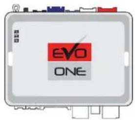

natural_image
Coiled black cable with red and blue connectors, no visible text or symbolsSTEP 1. CONFIGURE THE REMOTE STARTER
The Fortin Flashlink is required to properly configure the EVO-ONE remote starter to accept the telematic device. When flashing the EVO-ONE remote starter, please ensure to choose the following options: Toggle your Flashlink connection mode to "Remote-Starter". From the top menu click on "Configuration" and then on "Unit Options". In the "RF Kit Compatible" section, check the box next to "Fortin 2" and click the save button on the top right of the screen.
STEP 2. CONNECT
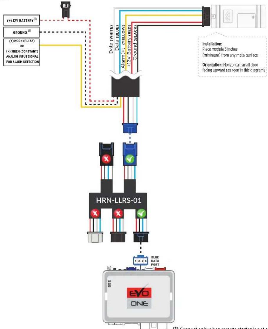
flowchart
graph TD
    A[" (+ ) 12V BATTERY (1) "] --> B[" Ground (1) "]
    C[" (+ ) HORN (PULSE) OR (+ ) SIREN (CONSTANT) ANALOG INPUT SIGNAL FOR ALARM DETECTION "] --> B
    B --> D[" Data (WHITE) Data (BLUE) +12V Battery (RED) Ground (BLACK) "]
    D --> E[" HRN-LLRS-01 "]
    E --> F[" Blue DATA PORT (1) EVO ONE "]
    G[" Installation: Place module 3 inches (minimum) from any metal surface"] --> D
    H[" Orientation: Horizontal: small door facing upward (as seen in this diagram) "] --> D
CAR:LINK™
INSTALLATION, WIRING & PROGRAMMING GUIDE
STEP 3. NETWORK CONNECTIVITY
Once the telematics module is connected into the remote starter, two LED's will display to which networks you are connected to. (See LED Status Reference Chart on last page for details). NOTE: The vehicle may need to be outside in an open area in order to connect to a cellular and/or GPS network.
STEP 4. ADD A DEVICE/VEHICLE TO AN ACCOUNT
a. Click the “+” sign at the bottom right of the Application screen. This will allow you to temporarily add your customers device/vehicle to your personal account.
b. Enter the 16 digit "Serial Number" found at the back of the telematic device (SN: XXXXXX-XXXXXXXXXX) and Click "Submit the code".
c. You are now in "Test Mode". Test Mode will allow you up to 4 hours for you to test the newly installed device. At any time during this 4 hour period, you can exit testing mode and make unit "Ready for Customer Delivery" by "Releasing the vehicle" or by "Transferring the vehicle" from your account.
NOTE: If you do NOT remove the vehicle from your account, it will automatically be removed from your account and make the unit "Ready for Customer Delivery".
STEP 5. PRE-CONFIGURE MYCAR APPLICATION EXPERIENCE FOR YOUR CUSTOMER
a. Click on the newly added vehicle from the vehicle list to enter the control screen (the screen that will allow you to control the vehicle's remote start functions). This will automatically take you to the "Vehicle Configuration" page for this vehicle. You will be prompt to "Set a Bypass Protocol" to use this device. Click "Ok".
b. Now you must set the protocol for the telematic device. When combined with the Evo-One remote starter previously installed, you must set the protocol to "Fortin" and click "ACCEPT" then click "Done" at the top right corner.
c. Now please allow a moment (About 5 minutes) for the telematic device to update your protocol selection and reboot. After this wait period it will be available to accept commands from the App. In the vehicle control screen, the Device Signal icon located above the Stop button will display the connectivity status of your telematic device. If the icon is Grayed out, Please wait, Device is still Offline. If icon is Green, Device is Online and Ready to go.
d. Then from the top right click on of the Settings section edit the Vehicle name, configure the Auxiliaries that might have been added if applicable and click ACCEPT when done. Then choose the vehicle to display inside the control panel in the VEHICLE IMAGE section and click ACCEPT once done.
e. When your configurations are all completed, click "Done" at the top right corner. All Configurations will take effect.
STEP 6. LEARN THE MYCAR TELEMATICS DEVICE TO THE EVO-ONE
In order to communicate with the remote starter, the telematic system must be learned to the EVO-ONE.
1 - Cycle the ignition to the ON position.
2 - The YELLOW LED on top of the EVO-ONE should come ON.
3 - Press & Hold the EVO-ONE programming Valet button for 5 seconds.
4 - The RED LED on the side of the EVO-ONE will Flash rapidly.
5 - Release the push button.
6 - Press & Release the push button 5x times. Everytime the push button is pressed the parking lights & the RED LED on the side of the EVO-ONE will blink.
7 - Then Press & Release the Brake pedal.
8 - At that same moment the RED LED on the side of the EVO-ONE will blink once to confirm that the Telematic device ID has been learned to the EVO-ONE.
9 - Cycle the vehicle's ignition to the OFF position to Exit the EVO-ONE programming.
STEP 7. TEST YOUR DEVICE
When the system is Online you start testing the unit from the vehicle control panel. Test all the application functions (Start, Stop, Lock, Unlock, Auxiliaries, ETC.) When done with the testing, from the vehicle list you can “Release” the vehicle. There are 2x different method to release it to the new owner. Choosing “release” will simply remove it from your account and make it “Ready for Customer Delivery”. Choosing “transfer” will transfer the device to the new owner’s account.
Also make sure that the Owners Card is handed to the New Owner of the vehicle. Doing this will ensure that the instructions on how to setup their App, Account and Vehicle is done correctly by using the device serial number located on the sticker affixed by the installer at the time of installation.
PARTS REQUIRED FOR INSTALLATION OF : PRESTIGE (E) Models
Telematics device HRN-MCAR-01 (E) Model HRN-DRS-02

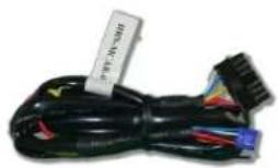

natural_image
Top-down schematic of a vehicle or enclosure with no text, numbers, or symbols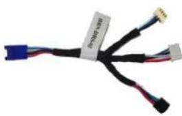
natural_image
Close-up of a black cable with three wires and connectors, no visible text or symbolsSTEP 1. CONFIGURE THE REMOTE STARTER
The Voxx VEPROG is required to upgrade the latest Firmware and properly configure the Prestige (E) remote starter to accept the telematics device. When updating the Prestige (E) remote starter, please ensure to choose the correct Protocol option from Programming Bank 2, Feature #18, Option 3 or 4 "ADS TEL".
STEP 2. CONNECT

flowchart
graph TD
    A["ECT"] --> B["+ 12V BATTERY (1)"]
    A --> C["GROUND (1)"]
    A --> D["+ HORN (PULSE) OR (+) SIREN (CONSTANT) ANALOG INPUT SIGNAL FOR ALARM DETECTION"]
    B --> E["HRN-DRS-02"]
    C --> E
    D --> E
    E --> F["TAN TELEMATICS PORT"]
    E --> G["PRO9776E"]
    E --> H["OR"]
    E --> I["Data (WHITE)"]
    E --> J["Data (BLUE)"]
    E --> K["Alarm(+) (YELLOW)"]
    E --> L["+12V Battery (RED)"]
    E --> M["Ground (BLACK)"]
    E --> N["Installation: Place module 3 inches (minimum) from any metal surface"]
    E --> O["Orientation: Horizontal; small door facing upward (as seen in this diagram)"]
(1) Connect to supply power to telematics device
CAR:LINK™
INSTALLATION, WIRING & PROGRAMMING GUIDE
STEP 3. NETWORK CONNECTIVITY
Once the telematics module is connected into the remote starter, two LED's will display to which networks you are connected to. (See LED Status Reference Chart on last page for details). NOTE: The vehicle may need to be outside in an open area in order to connect to a cellular and/or GPS network.
STEP 4. ADD A DEVICE/VEHICLE TO AN ACCOUNT
a. Click the “+” sign at the bottom right of the Application screen. This will allow you to temporarily add your customers device/vehicle to your personal account.
b. Enter the 16 digit "Serial Number" found at the back of the telematic device (SN: XXXXXX-XXXXXXXXXX) and Click "Submit the code".
c. You are now in "Test Mode". Test Mode will allow you up to 4 hours for you to test the newly installed device. At any time during this 4 hour period, you can exit testing mode and make unit "Ready for Customer Delivery" by "Releasing the vehicle" or by "Transferring the vehicle" from your account.
NOTE: If you do NOT remove the vehicle from your account, it will automatically be removed from your account and make the unit "Ready for Customer Delivery".
STEP 5. PRE-CONFIGURE MYCAR APPLICATION EXPERIENCE FOR YOUR CUSTOMER
a. Click on the newly added vehicle from the vehicle list to enter the control screen (the screen that will allow you to control the vehicle's remote start functions). This will automatically take you to the "Vehicle Configuration" page for this vehicle. You will be prompt to "Set a Bypass Protocol" to use this device. Click "Ok".
b. Now you must set the protocol for the telematic device. When combined with the Prestige (E) remote starter previously installed, you must set the protocol to "ADS" and click "ACCEPT" then click "Done" at the top right corner.
c. Now please allow a moment (About 5 minutes) for the telematic device to update your protocol selection and reboot. After this wait period it will be available to accept commands from the App. In the vehicle control screen, the Device Signal icon located above the Stop button will display the connectivity status of your telematic device. If the icon is Grayed out, Please wait, Device is still Offline. If icon is Green, Device is Online and Ready to go.
d. Then from the top right click on of the Settings section edit the Vehicle name, configure the Auxiliaries that might have been added if applicable and click ACCEPT when done. Then choose the vehicle to display inside the control panel in the VEHICLE IMAGE section and click ACCEPT once done.
e. When your configurations are all completed, click "Done" at the top right corner. All Configurations will take effect.
STEP 6. TEST YOUR DEVICE
When the system is Online you start testing the unit from the vehicle control panel. Test all the application functions (Start, Stop, Lock, Unlock, Auxiliaries, ETC.) When done with the testing, from the vehicle list you can “Release” the vehicle. There are 2x different method to release it to the new owner. Choosing “release” will simply remove it from your account and make it “Ready for Customer Delivery”. Choosing “transfer” will transfer the device to the new owner’s account.
Also make sure that the Owners Card is handed to the New Owner of the vehicle. Doing this will ensure that the instructions on how to setup their App, Account and Vehicle is done correctly by using the device serial number located on the sticker affixed by the installer at the time of installation.
PARTS REQUIRED FOR INSTALLATION OF : PRESTIGE (Z) Models
Telematics device HRN-MCAR-01 (Z) Model


STEP 1. CONFIGURE THE REMOTE STARTER
The ADS Weblink (ADS-USB) is required to properly configure the Prestige (Z) remote starter to accept the telematic device. When flashing the Prestige (Z) remote starter, please ensure to choose the correct Protocol option from Programming Bank 2, Data Port Protocol, "ADS".
STEP 2. CONNECT

flowchart
graph TD
    A["VOXX"] --> B["Blue DATA PORT"]
    B --> C["Data (WHITE)"]
    C --> D["Ground (BLACK)"]
    D --> E["+12V Battery (RED)"]
    E --> F["Alarm(+) (YELLOW)"]
    F --> G["Data (BLUE)"]
    G --> H["Ground"]
    H --> I["Data (BLUE)"]
    I --> J["+12V Battery (RED)"]
    J --> K["Ground"]
    K --> L["Data (BLUE)"]
    L --> M["Ground"]
    M --> N["Data (BLUE)"]
    N --> O["Ground"]
    O --> P["Data (BLUE)"]
    P --> Q["Ground"]
    Q --> R["Data (BLUE)"]
    R --> S["Ground"]
    S --> T["Data (BLUE)"]
    T --> U["Ground"]
    U --> V["Data (BLUE)"]
    V --> W["Ground"]
    W --> X["Data (BLUE)"]
    X --> Y["Ground"]
    Y --> Z["Data (BLUE)"]
    Z --> AA["Ground"]
    AA --> AB["Data (BLUE)"]
    AB --> AC["Ground"]
    AC --> AD["Data (BLUE)"]
    AD --> AE["Ground"]
    AE --> AF["Data (BLUE)"]
    AF --> AG["Ground"]
    AG --> AH["Data (BLUE)"]
    AH --> AI["Ground"]
    AI --> AJ["Data (BLUE)"]
    AJ --> AK["Ground"]
    AK --> AL["Data (BLUE)"]
    AL --> AM["Ground"]
    AM --> AN["Data (BLUE)"]
    AN --> AO["Ground"]
    AO --> AP["Data (BLUE)"]
    AP --> AQ["Ground"]
    AQ --> AR["Data (BLUE)"]
    AR --> AS["Ground"]
    AS --> AT["Data (BLUE)"]
    AT --> AU["Ground"]
    AU --> AV["Data (BLUE)"]
    AV --> AW["Ground"]
    AW --> AX["Data (BLUE)"]
    AX --> AY["Ground"]
    AY --> AZ["Data (BLUE)"]
    AZ --> BA["Ground"]
    BA --> BB["Data (BLUE)"]
    BB --> BC["Ground"]
    BC --> BD["Data (BLUE)"]
    BD --> BE["Ground"]
    BE --> BF["Data (BLUE)"]
    BF --> BG["Ground"]
    BG --> BH["Data (BLUE)"]
    BH --> BI["Ground"]
    BI --> BJ["Data (BLUE)"]
    BJ --> BK["Ground"]
    BK --> BL["Data (BLUE)"]
    BL --> BM["Ground"]
    BM --> BN["Data (BLUE)"]
    BN --> BO["Ground"]
    BO --> BP["Data (BLUE)"]
    BP --> BQ["Ground"]
    BQ --> BR["Data (BLUE)"]
    BR --> BS["Ground"]
    BS --> BT["Data (BLUE)"]
    BT --> BU["Ground"]
    BU --> BV["Data (BLUE)"]
    BV --> BW["Ground"]
    BW --> BX["Data (BLUE)"]
    BX --> BY["Ground"]
    BY --> BZ["Data (BLUE)"]
    BZ --> CA["Ground"]
    CA --> CB["Data (BLUE)"]
    CB --> CC["Ground"]
    CC --> CD["Data (BLUE)"]
    CD --> CE["Ground"]
    CE --> CF["Data (BLUE)"]
    CF --> CG["Ground"]
    CG --> CH["Data (BLUE)"]
    CH --> CI["Ground"]
    CI --> CJ["Data (BLUE)"]
    CJ --> CK["Ground"]
CAR:LINK™
INSTALLATION, WIRING & PROGRAMMING GUIDE
STEP 3. NETWORK CONNECTIVITY
Once the telematics module is connected into the remote starter, two LED's will display to which networks you are connected to. (See LED Status Reference Chart on last page for details). NOTE: The vehicle may need to be outside in an open area in order to connect to a cellular and/or GPS network.
STEP 4. ADD A DEVICE/VEHICLE TO AN ACCOUNT
a. Click the “+” sign at the bottom right of the Application screen. This will allow you to temporarily add your customers device/vehicle to your personal account.
b. Enter the 16 digit "Serial Number" found at the back of the telematic device (SN: XXXXXX-XXXXXXXXXX) and Click "Submit the code".
c. You are now in "Test Mode". Test Mode will allow you up to 4 hours for you to test the newly installed device. At any time during this 4 hour period, you can exit testing mode and make unit "Ready for Customer Delivery" by "Releasing the vehicle" or by "Transferring the vehicle" from your account.
NOTE: If you do NOT remove the vehicle from your account, it will automatically be removed from your account and make the unit "Ready for Customer Delivery".
STEP 5. PRE-CONFIGURE MYCAR APPLICATION EXPERIENCE FOR YOUR CUSTOMER
a. Click on the newly added vehicle from the vehicle list to enter the control screen (the screen that will allow you to control the vehicle's remote start functions). This will automatically take you to the "Vehicle Configuration" page for this vehicle. You will be prompt to "Set a Bypass Protocol" to use this device. Click "Ok".
b. Now you must set the protocol for the telematic device. When combined with the Prestige (Z) remote starter previously installed, you must set the protocol to "ADS" and click "ACCEPT" then click "Done" at the top right corner.
c. Now please allow a moment (About 5 minutes) for the telematic device to update your protocol selection and reboot. After this wait period it will be available to accept commands from the App. In the vehicle control screen, the Device Signal icon located above the Stop button will display the connectivity status of your telematic device. If the icon is Grayed out, Please wait, Device is still Offline. If icon is Green, Device is Online and Ready to go.
d. Then from the top right click on of the Settings section edit the Vehicle name, configure the Auxiliaries that might have been added if applicable and click ACCEPT when done. Then choose the vehicle to display inside the control panel in the VEHICLE IMAGE section and click ACCEPT once done.
e. When your configurations are all completed, click "Done" at the top right corner. All Configurations will take effect.
STEP 6. TEST YOUR DEVICE
When the system is Online you start testing the unit from the vehicle control panel. Test all the application functions (Start, Stop, Lock, Unlock, Auxiliaries, ETC.) When done with the testing, from the vehicle list you can “Release” the vehicle. There are 2x different method to release it to the new owner. Choosing “release” will simply remove it from your account and make it “Ready for Customer Delivery”. Choosing “transfer” will transfer the device to the new owner’s account.
Also make sure that the Owners Card is handed to the New Owner of the vehicle. Doing this will ensure that the instructions on how to setup their App, Account and Vehicle is done correctly by using the device serial number located on the sticker affixed by the installer at the time of installation.
PARTS REQUIRED FOR INSTALLATION OF : PURSUIT (E) Models
Telematics device HRN-MCAR-01 (E) Model (Exc.PRO9233E) HRN-DRS-02


natural_image
Top-down schematic of a vehicle or enclosure with no text, numbers, or symbols
natural_image
Close-up of a black cable with three wires and connectors, no visible text or symbolsSTEP 1. CONFIGURE THE REMOTE STARTER
The Voxx VEPROG is required to upgrade the latest Firmware and properly configure the Pursuit (E) remote starter to accept the telematics device. When updating the Pursuit (E) remote starter, please ensure to choose the correct Protocol option from Programming Bank 2, Feature #18, Option 3 or 4 "ADS TEL".
STEP 2. CONNECT
STEP 3. NETWORK CONNECTIVITY

flowchart
graph TD
    A["ORK CONNECTIVITY"] --> B["(+) 12V BATTERY (1)"]
    A --> C["GROUND (1)"]
    A --> D["(+) HORN (PULSE) OR (+) SIREN (CONSTANT) ANALOG INPUT SIGNAL FOR ALARM DETECTION"]
    A --> E["HRN-DRS-02"]
    E --> F["Data (WHITE)"]
    E --> G["Data (BLUE)"]
    E --> H["Alarm(+) (YELLOW)"]
    E --> I["+12V Battery (RED)"]
    E --> J["Ground (BLACK)"]
    E --> K["TAN TELEMATICS POINT"]
    E --> L["TAN TELEMATICS POINT"]
    M["Installation: Place module 3 inches (minimum) from any metal surface"] --> N["Orientation: Horizontal; small door facing upward (as seen in this diagram)"]
(1) Connect to supply power to telematics device
CAR:LINK™
INSTALLATION, WIRING & PROGRAMMING GUIDE
Once the telematics module is connected into the remote starter, two LED's will display to which networks you are connected to. (See LED Status Reference Chart on last page for details). NOTE: The vehicle may need to be outside in an open area in order to connect to a cellular and/or GPS network.
STEP 4. ADD A DEVICE/VEHICLE TO AN ACCOUNT
a. Click the “+” sign at the bottom right of the Application screen. This will allow you to temporarily add your customers device/vehicle to your personal account.
b. Enter the 16 digit "Serial Number" found at the back of the telematic device
(SN: XXXXXX-XXXXXXXXXX) and Click "Submit the code".
c. You are now in “Test Mode”. Test Mode will allow you up to 4 hours for you to test the newly installed device. At any time during this 4 hour period, you can exit testing mode and make unit “Ready for Customer Delivery” by “Releasing the vehicle” or by “Transferring the vehicle” from your account.
NOTE: If you do NOT remove the vehicle from your account, it will automatically be removed from your account and make the unit "Ready for Customer Delivery".
STEP 5. PRE-CONFIGURE MYCAR APPLICATION EXPERIENCE FOR YOUR CUSTOMER
a. Click on the newly added vehicle from the vehicle list to enter the control screen (the screen that will allow you to control the vehicle's remote start functions). This will automatically take you to the "Vehicle Configuration" page for this vehicle. You will be prompt to "Set a Bypass Protocol" to use this device. Click "Ok".
b. Now you must set the protocol for the telematic device. When combined with the Pursuit (E) remote starter previously installed, you must set the protocol to "ADS" and click "ACCEPT" then click "Done" at the top right corner.
c. Now please allow a moment (About 5 minutes) for the telematic device to update your protocol selection and reboot. After this wait period it will be available to accept commands from the App. In the vehicle control screen, the Device Signal icon located above the Stop button will display the connectivity status of your telematic device. If the icon is Grayed out, Please wait, Device is still Offline. If icon is Green, Device is Online and Ready to go.
d. Then from the top right click on of the Settings section edit the Vehicle name, configure the Auxiliaries that might have been added if applicable and click ACCEPT when done. Then choose the vehicle to display inside the control panel in the VEHICLE IMAGE section and click ACCEPT once done.
e. When your configurations are all completed, click "Done" at the top right corner. All Configurations will take effect.
STEP 6. TEST YOUR DEVICE
When the system is Online you start testing the unit from the vehicle control panel. Test all the application functions (Start, Stop, Lock, Unlock, Auxiliaries, ETC.) When done with the testing, from the vehicle list you can “Release” the vehicle. There are 2x different method to release it to the new owner. Choosing “release” will simply remove it from your account and make it “Ready for Customer Delivery”. Choosing “transfer” will transfer the device to the new owner’s account.
Also make sure that the Owners Card is handed to the New Owner of the vehicle. Doing this will ensure that the instructions on how to setup their App, Account and Vehicle is done correctly by using the device serial number located on the sticker affixed by the installer at the time of installation.
PARTS REQUIRED FOR INSTALLATION OF: CODE SYSTEMS
Telematics device HRN-MCAR-01


CASECRS, CARS, CA4555, CA4055 or CA5055

HRN-DRS-02

natural_image
Coiled electronic circuit board with blue and black wires, no visible text or symbolsSTEP 1. CONFIGURE THE REMOTE STARTER
The Voxx VEPROG is required to upgrade the latest Firmware and properly configure the Code Alarm CASECRS, CARS, CA4555, CA4055 or CA5055 remote starter to accept the telematics device. When updating the Code Alarm CASECRS, CARS, CA4555, CA4055 or CA5055 remote starter, please ensure to choose the correct Protocol option from Programming Bank 2, Feature #9, Option 3 or 4 "ADS TEL".
STEP 2. CONNECT
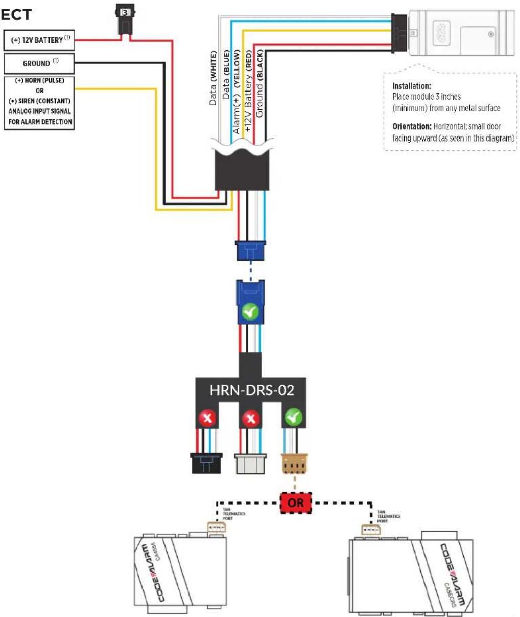
flowchart
graph TD
    A["ECT"] --> B["HRN-DRS-02"]
    B --> C["Data (WHITE)"]
    B --> D["Ground (BLACK)"]
    B --> E["Alarm (+) (YELLOW)"]
    B --> F["+12V Battery (RED)"]
    B --> G["GROUND (I)"]
    B --> H["Ground (BLUE)"]
    B --> I["Data (BLUE)"]
    B --> J["Ground (Black)"]
    B --> K["HRN-DRS-02"]
    K --> L["TAIN TELEMATICS PORT"]
    K --> M["TAIN TELEMATICS PORT"]
    K --> N["OR"]
    N --> O["CODE/ALARM CASECLOS"]
    style A fill:#f9f,stroke:#333
    style B fill:#ccf,stroke:#333
    style K fill:#cfc,stroke:#333
CAR:LINK™
INSTALLATION, WIRING & PROGRAMMING GUIDE
STEP 3. NETWORK CONNECTIVITY
Once the telematics module is connected into the remote starter, two LED's will display to which networks you are connected to. (See LED Status Reference Chart on last page for details). NOTE: The vehicle may need to be outside in an open area in order to connect to a cellular and/or GPS network.
STEP 4. ADD A DEVICE/VEHICLE TO AN ACCOUNT
a. Click the “+” sign at the bottom right of the Application screen. This will allow you to temporarily add your customers device/vehicle to your personal account.
b. Enter the 16 digit "Serial Number" found at the back of the telematic device (SN: XXXXXX-XXXXXXXXXX) and Click "Submit the code".
c. You are now in "Test Mode". Test Mode will allow you up to 4 hours for you to test the newly installed device. At any time during this 4 hour period, you can exit testing mode and make unit "Ready for Customer Delivery" by "Releasing the vehicle" or by "Transferring the vehicle" from your account.
NOTE: If you do NOT remove the vehicle from your account, it will automatically be removed from your account and make the unit "Ready for Customer Delivery".
STEP 5. PRE-CONFIGURE MYCAR APPLICATION EXPERIENCE FOR YOUR CUSTOMER
a. Click on the newly added vehicle from the vehicle list to enter the control screen (the screen that will allow you to control the vehicle's remote start functions). This will automatically take you to the "Vehicle Configuration" page for this vehicle. You will be prompt to "Set a Bypass Protocol" to use this device. Click "Ok".
b. Now you must set the protocol for the telematic device. When combined with the Code Alarm remote starter previously installed, you must set the protocol to "ADS" and click "ACCEPT" then click "Done" at the top right corner.
c. Now please allow a moment (About 5 minutes) for the telematic device to update your protocol selection and reboot. After this wait period it will be available to accept commands from the App. In the vehicle control screen, the Device Signal icon located above the Stop button will display the connectivity status of your telematic device. If the icon is Grayed out, Please wait, Device is still Offline. If icon is Green, Device is Online and Ready to go.
d. Then from the top right click on of the Settings section edit the Vehicle name, configure the Auxiliaries that might have been added if applicable and click ACCEPT when done. Then choose the vehicle to display inside the control panel in the VEHICLE IMAGE section and click ACCEPT once done.
e. When your configurations are all completed, click "Done" at the top right corner. All Configurations will take effect.
STEP 6. TEST YOUR DEVICE
When the system is Online you start testing the unit from the vehicle control panel. Test all the application functions (Start, Stop, Lock, Unlock, Auxiliaries, ETC.) When done with the testing, from the vehicle list you can “Release” the vehicle. There are 2x different method to release it to the new owner. Choosing “release” will simply remove it from your account and make it “Ready for Customer Delivery”. Choosing “transfer” will transfer the device to the new owner’s account.
Also make sure that the Owners Card is handed to the New Owner of the vehicle. Doing this will ensure that the instructions on how to setup their App, Account and Vehicle is done correctly by using the device serial number located on the sticker affixed by the installer at the time of installation.
PARTS REQUIRED FOR INSTALLATION OF : OLDER CODE SYSTEMS
Telematics device HRN-MCAR-01

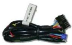
natural_image
Coiled black cable with various connectors and wires, no visible text or symbolsOLDER CODE SYSTEMS

HRN-DRS-02

natural_image
Coiled electrical cable with connectors and a small component labeled '铜工制造' (Copper Manufacturing) on top right (no other text or symbols visible)IMPORTANT NOTE: THESE OLDER MODELS ARE NOT SUPPORTED BY THIS PRODUCT.
PARTS REQUIRED FOR INSTALLATION OF : OMEGA RS-X70
Telematics device HRN-MCAR-01 RS-X70 BLADE-AL (64)


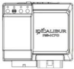
natural_image
Line drawing of a laboratory equipment unit labeled 'EXCALIBUR PAB-CTO' (no additional text or symbols)HRN-DRS-02 & HRN-LLRS-01

natural_image
Two black cable connectors with blue and red wires, no text or symbols visible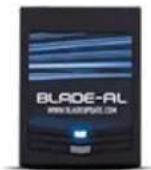
STEP 1. CONFIGURE THE REMOTE STARTER
The ADS Weblink (ADS-USB) is required to properly configure the Omega RS-X70 remote starter to accept the telematics device. When flashing the Omega RS-X70 remote starter, please ensure the remote starter firmware and BLADE-AL (64) firmwares are updated to the latest firmware available. Also ensure to set the "Data Port Protocol" to: "Green = iData".
STEP 2. CONNECT

flowchart
graph TD
    A[" (+ ) 12V BATTERY (①)"] --> B[" GROUND (②) "]
    B --> C[" (+ ) HORN (PULSE) OR (+ ) SIREN (CONSTANT) ANALOG INPUT SIGNAL FOR ALARM DETECTION "]
    C --> D[" OR "]
    D --> E[" AIR CALIBUR FIS-X70 "]
    D --> F[" GREEN DATA PORT "]
    D --> G[" HRN-LLRS-01 "]
    D --> H[" HRN-DRS-01 "]
    D --> I[" METHOD #1 "]
    D --> J[" METHOD #2 "]
    D --> K[" METHOD #3 "]
    D --> L[" METHOD #4"]
    D --> M[" Data (WHITE) Data (BLUE) +12V Battery (RED) Ground (BLACK)"]
    style A fill:#f9f,stroke:#333
    style B fill:#f9f,stroke:#333
    style C fill:#f9f,stroke:#333
    style D fill:#ccf,stroke:#333
    style E fill:#cff,stroke:#333
    style F fill:#cff,stroke:#333
    style G fill:#cff,stroke:#333
    style H fill:#cff,stroke:#333
    style I fill:#cff,stroke:#333
    style J fill:#cff,stroke:#333
    style K fill:#cff,stroke:#333
    style L fill:#ffc,stroke:#333
(1) Connect only when remote starter is not supplying power to telematics device
CAR:LINK™
INSTALLATION, WIRING & PROGRAMMING GUIDE
STEP 3. NETWORK CONNECTIVITY
Once the telematics module is connected into the remote starter, two LED's will display to which networks you are connected to. (See LED Status Reference Chart on last page for details). NOTE: The vehicle may need to be outside in an open area in order to connect to a cellular and/or GPS network.
STEP 4. ADD A DEVICE/VEHICLE TO AN ACCOUNT
a. Click the “+” sign at the bottom right of the Application screen. This will allow you to temporarily add your customers device/vehicle to your personal account.
b. Enter the 16 digit "Serial Number" found at the back of the telematic device (SN: XXXXXX-XXXXXXXXXX) and Click "Submit the code".
c. You are now in "Test Mode". Test Mode will allow you up to 4 hours for you to test the newly installed device. At any time during this 4 hour period, you can exit testing mode and make unit "Ready for Customer Delivery" by "Releasing the vehicle" or by "Transferring the vehicle" from your account.
NOTE: If you do NOT remove the vehicle from your account, it will automatically be removed from your account and make the unit "Ready for Customer Delivery".
STEP 5. PRE-CONFIGURE MYCAR APPLICATION EXPERIENCE FOR YOUR CUSTOMER
a. Click on the newly added vehicle from the vehicle list to enter the control screen (the screen that will allow you to control the vehicle's remote start functions). This will automatically take you to the "Vehicle Configuration" page for this vehicle. You will be prompt to "Set a Bypass Protocol" to use this device. Click "Ok".
b. Now you must set the protocol for the telematic device. When combined with the Omega RS-X70 remote starter previously installed, you must set the protocol to "ADS" and click "ACCEPT" then click "Done" at the top right corner.
c. Now please allow a moment (About 5 minutes) for the telematic device to update your protocol selection and reboot. After this wait period it will be available to accept commands from the App. In the vehicle control screen, the Device Signal icon located above the Stop button will display the connectivity status of your telematic device. If the icon is Grayed out, Please wait, Device is still Offline. If icon is Green, Device is Online and Ready to go.
d. Then from the top right click on of the Settings section edit the Vehicle name, configure the Auxiliaries that might have been added if applicable and click ACCEPT when done. Then choose the vehicle to display inside the control panel in the VEHICLE IMAGE section and click ACCEPT once done.
e. When your configurations are all completed, click "Done" at the top right corner. All Configurations will take effect.
STEP 6. TEST YOUR DEVICE
When the system is Online you start testing the unit from the vehicle control panel. Test all the application functions (Start, Stop, Lock, Unlock, Auxiliaries, ETC.) When done with the testing, from the vehicle list you can “Release” the vehicle. There are 2x different method to release it to the new owner. Choosing “release” will simply remove it from your account and make it “Ready for Customer Delivery”. Choosing “transfer” will transfer the device to the new owner’s account.
Also make sure that the Owners Card is handed to the New Owner of the vehicle. Doing this will ensure that the instructions on how to setup their App, Account and Vehicle is done correctly by using the device serial number located on the sticker affixed by the installer at the time of installation.
PARTS REQUIRED FOR INSTALLATION OF : OMEGA AL-XX70-B
Telematics device HRN-MCAR-01 AL-XX70-B BLADE-AL (64)
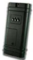


natural_image
Line drawing of a device labeled 'SICALIBUR ALAOCPOH' with control buttons and ports (no readable text beyond branding)HRN-DRS-02 & HRN-LLRS-01
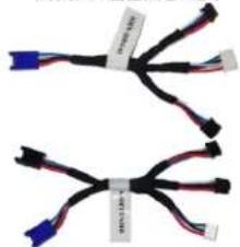
natural_image
Two identical black cable connectors with blue and red wires, no text or symbols visible
STEP 1. CONFIGURE THE REMOTE STARTER
The ADS Weblink (ADS-USB) is required to properly configure the Omega AL-XX70-B remote starter to accept the telematics device. When flashing the Omega AL-XX70-B remote starter, please ensure the remote starter firmware and BLADE-AL (64) firmwares are updated to the latest firmware available. Also ensure to set the "Data Port Protocol" to: "Green = iData".
STEP 2. CONNECT

flowchart
graph TD
    A["+"] 12V BATTERY (1)] -->|Ground (1)| B["OR"]
    C["+"] HORN (PULSE) OR (+) SIREN (CONSTANT) ANALOG INPUT SIGNAL FOR ALARM DETECTION] -->|Data (WHITE)| D["Data (BLUE)"]
    D --> E["Alarm (+) (YELLOW) +12V Battery (RED)"]
    D --> F["Ground (BLACK)"]
    G["GREEN DATA PORT"] --> H["HL-COFFER EQ"]
    H --> I["HRN LLRS 01"]
    H --> J["HRN DRS 01"]
    K["Black DATA PORT"] --> L["OK CALIBUR AL-DCFF84"]
    M["Installation: Place module 3 inches (minimum) from any metal surface"] --> N["Orientation: Horizontal, small door facing upward (as seen in this diagram)"]
    style A fill:#f9f,stroke:#333
    style C fill:#f9f,stroke:#333
    style G fill:#ccf,stroke:#333
    style K fill:#cfc,stroke:#333
    style M fill:#fcc,stroke:#333
(1) Connect only when remote starter is not supplying power to telematics device
CAR:LINK™
INSTALLATION, WIRING & PROGRAMMING GUIDE
STEP 3. NETWORK CONNECTIVITY
Once the telematics module is connected into the remote starter, two LED's will display to which networks you are connected to. (See LED Status Reference Chart on last page for details). NOTE: The vehicle may need to be outside in an open area in order to connect to a cellular and/or GPS network.
STEP 4. ADD A DEVICE/VEHICLE TO AN ACCOUNT
a. Click the “+” sign at the bottom right of the Application screen. This will allow you to temporarily add your customers device/vehicle to your personal account.
b. Enter the 16 digit "Serial Number" found at the back of the telematic device (SN: XXXXXX-XXXXXXXXXX) and Click "Submit the code".
c. You are now in "Test Mode". Test Mode will allow you up to 4 hours for you to test the newly installed device. At any time during this 4 hour period, you can exit testing mode and make unit "Ready for Customer Delivery" by "Releasing the vehicle" or by "Transferring the vehicle" from your account.
NOTE: If you do NOT remove the vehicle from your account, it will automatically be removed from your account and make the unit "Ready for Customer Delivery".
STEP 5. PRE-CONFIGURE MYCAR APPLICATION EXPERIENCE FOR YOUR CUSTOMER
a. Click on the newly added vehicle from the vehicle list to enter the control screen (the screen that will allow you to control the vehicle's remote start functions). This will automatically take you to the "Vehicle Configuration" page for this vehicle. You will be prompt to "Set a Bypass Protocol" to use this device. Click "Ok".
b. Now you must set the protocol for the telematic device. When combined with the Omega AL-XX70-B remote starter previously installed, you must set the protocol to "ADS" and click "ACCEPT" then click "Done" at the top right corner.
c. Now please allow a moment (About 5 minutes) for the telematic device to update your protocol selection and reboot. After this wait period it will be available to accept commands from the App. In the vehicle control screen, the Device Signal icon located above the Stop button will display the connectivity status of your telematic device. If the icon is Grayed out, Please wait, Device is still Offline. If icon is Green, Device is Online and Ready to go.
d. Then from the top right click on of the Settings section edit the Vehicle name, configure the Auxiliaries that might have been added if applicable and click ACCEPT when done. Then choose the vehicle to display inside the control panel in the VEHICLE IMAGE section and click ACCEPT once done.
e. When your configurations are all completed, click "Done" at the top right corner. All Configurations will take effect.
STEP 6. TEST YOUR DEVICE
When the system is Online you start testing the unit from the vehicle control panel. Test all the application functions (Start, Stop, Lock, Unlock, Auxiliaries, ETC.) When done with the testing, from the vehicle list you can “Release” the vehicle. There are 2x different method to release it to the new owner. Choosing “release” will simply remove it from your account and make it “Ready for Customer Delivery”. Choosing “transfer” will transfer the device to the new owner’s account.
Also make sure that the Owners Card is handed to the New Owner of the vehicle. Doing this will ensure that the instructions on how to setup their App, Account and Vehicle is done correctly by using the device serial number located on the sticker affixed by the installer at the time of installation.
PARTS REQUIRED FOR INSTALLATION OF : DSE 503AIR 5R-85
Telematics device HRN-MCAR-01 DSE 503AIR 5R85


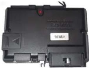
natural_image
Black electronic device casing with indicator lights and a label reading '503Air' (no readable text beyond label)STEP 1. CONFIGURE THE REMOTE STARTER
The 503Air is already pre-configured to accept the telematics device. No extra programming required.
STEP 2. CONNECT

flowchart
graph TD
    A["3"] --> B["(+) 12V BATTERY¹"]
    A --> C["GROUND¹"]
    A --> D["(+) HORN (PULSE) OR (+) SIREN (CONSTANT) ANALOG INPUT SIGNAL FOR ALARM DETECTION"]
    B --> E["Data (WHITE)"]
    C --> F["Data (BLUE)"]
    D --> G["Ground (BLACK)"]
    E --> H["White DATA PORT 1 2 3 4"]
    F --> H
    G --> H
    H --> I["Installation: Place module 3 inches (minimum) from any metal surface"]
    H --> J["Orientation: Horizontal; small door facing upward (as seen in this diagram)"]
CAR:LINK™
INSTALLATION, WIRING & PROGRAMMING GUIDE
STEP 3. NETWORK CONNECTIVITY
Once the telematics module is connected into the remote starter, two LED's will display to which networks you are connected to. (See LED Status Reference Chart on last page for details). NOTE: The vehicle may need to be outside in an open area in order to connect to a cellular and/or GPS network.
STEP 4. ADD A DEVICE/VEHICLE TO AN ACCOUNT
a. Click the “+” sign at the bottom right of the Application screen. This will allow you to temporarily add your customers device/vehicle to your personal account.
b. Enter the 16 digit "Serial Number" found at the back of the telematic device (SN: XXXXXX-XXXXXXXXXX) and Click "Submit the code".
c. You are now in "Test Mode". Test Mode will allow you up to 4 hours for you to test the newly installed device. At any time during this 4 hour period, you can exit testing mode and make unit "Ready for Customer Delivery" by "Releasing the vehicle" or by "Transferring the vehicle" from your account.
NOTE: If you do NOT remove the vehicle from your account, it will automatically be removed from your account and make the unit "Ready for Customer Delivery".
STEP 5. PRE-CONFIGURE MYCAR APPLICATION EXPERIENCE FOR YOUR CUSTOMER
a. Click on the newly added vehicle from the vehicle list to enter the control screen (the screen that will allow you to control the vehicle's remote start functions). This will automatically take you to the "Vehicle Configuration" page for this vehicle. You will be prompt to "Set a Bypass Protocol" to use this device. Click "Ok".
b. Now you must set the protocol for the telematic device. When combined with the DSE 503AIR remote starter previously installed, you must set the protocol to "ADS" and click "ACCEPT" then click "Done" at the top right corner.
c. Now please allow a moment (About 5 minutes) for the telematic device to update your protocol selection and reboot. After this wait period it will be available to accept commands from the App. In the vehicle control screen, the Device Signal icon located above the Stop button will display the connectivity status of your telematic device. If the icon is Grayed out, Please wait, Device is still Offline. If icon is Green, Device is Online and Ready to go.
d. Then from the top right click on of the Settings section edit the Vehicle name, configure the Auxiliaries that might have been added if applicable and click ACCEPT when done. Then choose the vehicle to display inside the control panel in the VEHICLE IMAGE section and click ACCEPT once done.
e. When your configurations are all completed, click "Done" at the top right corner. All Configurations will take effect.
STEP 6. TEST YOUR DEVICE
When the system is Online you start testing the unit from the vehicle control panel. Test all the application functions (Start, Stop, Lock, Unlock, Auxiliaries, ETC.) When done with the testing, from the vehicle list you can “Release” the vehicle. There are 2x different method to release it to the new owner. Choosing “release” will simply remove it from your account and make it “Ready for Customer Delivery”. Choosing “transfer” will transfer the device to the new owner’s account.
Also make sure that the Owners Card is handed to the New Owner of the vehicle. Doing this will ensure that the instructions on how to setup their App, Account and Vehicle is done correctly by using the device serial number located on the sticker affixed by the installer at the time of installation.
PARTS REQUIRED FOR INSTALLATION OF : DSE iSTART2 - 3
Telematics device HRN
MCAR-01 DSE iStart2 - 3 C
3R-86 BLADE-AL (64)


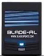
STEP 1. CONFIGURE THE REMOTE STARTER
The ADS Weblink (ADS-USB) is required to properly configure the DSE iStart2 - iStart3 remote starter to accept the telematics device. When flashing the DSE iStart2 - iStart3 remote starter, please ensure the remote starter firmware and BLADE-AL (64) firmwares are updated to the latest firmware available.
STEP 2. CONNECT

flowchart
graph TD
    A["3"] --> B["(+) 12V BATTERY¹"]
    A --> C["GROUND¹"]
    A --> D["(+) HORN (PULSE) OR (+) SIREN (CONSTANT) ANALOG INPUT SIGNAL FOR ALARM DETECTION"]
    B --> E["Data (WHITE)"]
    C --> E
    D --> E
    E --> F["Data (BLUE)"]
    E --> G["Alarm(+) (YELLOW) +12V Battery (RED)"]
    E --> H["Ground (BLACK)"]
    F --> I["White DATA PORT 1 2 3 4"]
    G --> I
    H --> I
    I --> J["Installation: Place module 3 inches (minimum) from any metal surface"]
    I --> K["Orientation: Horizontal; small door facing upward (as seen in this diagram)"]
CAR:LINK™
INSTALLATION, WIRING & PROGRAMMING GUIDE
STEP 3. NETWORK CONNECTIVITY
Once the telematics module is connected into the remote starter, two LED's will display to which networks you are connected to. (See LED Status Reference Chart on last page for details). NOTE: The vehicle may need to be outside in an open area in order to connect to a cellular and/or GPS network.
STEP 4. ADD A DEVICE/VEHICLE TO AN ACCOUNT
a. Click the “+” sign at the bottom right of the Application screen. This will allow you to temporarily add your customers device/vehicle to your personal account.
b. Enter the 16 digit "Serial Number" found at the back of the telematic device (SN: XXXXXX-XXXXXXXXXX) and Click "Submit the code".
c. You are now in "Test Mode". Test Mode will allow you up to 4 hours for you to test the newly installed device. At any time during this 4 hour period, you can exit testing mode and make unit "Ready for Customer Delivery" by "Releasing the vehicle" or by "Transferring the vehicle" from your account.
NOTE: If you do NOT remove the vehicle from your account, it will automatically be removed from your account and make the unit "Ready for Customer Delivery".
STEP 5. PRE-CONFIGURE MYCAR APPLICATION EXPERIENCE FOR YOUR CUSTOMER
a. Click on the newly added vehicle from the vehicle list to enter the control screen (the screen that will allow you to control the vehicle's remote start functions). This will automatically take you to the "Vehicle Configuration" page for this vehicle. You will be prompt to "Set a Bypass Protocol" to use this device. Click "Ok".
b. Now you must set the protocol for the telematic device. When combined with the DSE iStart2 - iStart3 remote starter previously installed, you must set the protocol to "ADS" and click "ACCEPT" then click "Done" at the top right corner.
c. Now please allow a moment (About 5 minutes) for the telematic device to update your protocol selection and reboot. After this wait period it will be available to accept commands from the App. In the vehicle control screen, the Device Signal icon located above the Stop button will display the connectivity status of your telematic device. If the icon is Grayed out, Please wait, Device is still Offline. If icon is Green, Device is Online and Ready to go.
d. Then from the top right click on of the Settings section edit the Vehicle name, configure the Auxiliaries that might have been added if applicable and click ACCEPT when done. Then choose the vehicle to display inside the control panel in the VEHICLE IMAGE section and click ACCEPT once done.
e. When your configurations are all completed, click "Done" at the top right corner. All Configurations will take effect.
STEP 6. TEST YOUR DEVICE
When the system is Online you start testing the unit from the vehicle control panel. Test all the application functions (Start, Stop, Lock, Unlock, Auxiliaries, ETC.) When done with the testing, from the vehicle list you can “Release” the vehicle. There are 2x different method to release it to the new owner. Choosing “release” will simply remove it from your account and make it “Ready for Customer Delivery”. Choosing “transfer” will transfer the device to the new owner’s account.
Also make sure that the Owners Card is handed to the New Owner of the vehicle. Doing this will ensure that the instructions on how to setup their App, Account and Vehicle is done correctly by using the device serial number located on the sticker affixed by the installer at the time of installation.
CAR:LINK™
INSTALLATION, WIRING & PROGRAMMING GUIDE
| LED Status Reference Chart | ||
| LED Status | GREEN LED : Cellular Network RED LED | : GPS Network |
| OFF No Cellular Network. No power to device. No GPS Network. | No power to device. | |
| Flashing Searching/Connecting Searching/Connecting | ||
| ON Solid Connection is established Connection is established | ||
RESET PROCEDURE
1 - Disconnect the main harness from the MyCar device.
2 - Wait approximately 10 seconds and reconnect the main harness to the MyCar device.
3 - Reset procedure Completed.
CAR:LINK™

180 Marcus Blvd.
Hauppauge, NY
11788 - USA
CAR:LINK™
QUICK INSTALLATION GUIDE
DOC DATE: 110317
1. CONFIGURE THE REMOTE STARTER
a. To configure the remote starter to accept the CL6 telematics device, refer to the Detailed Installation and Programming guide for more details. To access these guides, visit www.CL6.com. Complete the remote starter installation and confirm that it is working properly before connecting the CL6 device.
2. CONNECT
a. Connect the CL6 telematics device by following the remote starter connection guide as shown on the back of this page. A detailed wiring diagram can also be found in the Detailed Installation and Programming guide. (see Section #1 above for more details.)
3. NETWORK CONNECTIVITY
a. Once the telematics module is plugged into the remote starter, two LED's will display what networks you are connected to.
b. LED STATUS
» Green LED Status : Cellular Network
ii. Flashing : Connecting to Network
iii. On Solid : Connection established
NOTE: The vehicle may need to be outside in an open area in order to connect to a cellular and/or GPS network.
4. INSTALL THE CL6 APPLICATION
a. Go to the App store (Apple) or Play store (Android)
b. Search for "CL6"
c. Download and install the Free Application
5. CREATE AN ACCOUNT
NOTE: Already have an account? Go to the next step.
a. Launch the newly installed CL6 Application on your smartphone or tablet
b. Click "Create an Account"
c. Fill in all the required fields
d. Once completed, click "Create your Account"
e. Open your Mail and look for a new email sent from "MYCARCONTROLS"
f. To activate your account and create your secure password, click the embedded link in the email.
g. Create your secure password and activate your account.
h. Once done, Log into the Application using your email and your newly created password.
6. ADD A DEVICE/VEHICLE
a. In order to Pre-Configure your customer's CL6 Application, click the "+" sign at the bottom right of the Application screen to temporarily add your customers device/vehicle to your personal account.
b. Enter the 16 digit "Serial Number" found at the back of the device. (SN: XXXXXX-XXXXXXXXXX)
c. Click "Submit the code"
7. PRE-CONFIGURE CL6 APPLICATION EXPERIENCE FOR YOUR CUSTOMER
a. From the "My Car Settings" menu configure the following
b. Edit the Vehicle name
c. Configure the Auxiliaries if needed. i.e.: Trunk release and associate the Auxiliary to activate when Aux button is pressed.
d. Edit the Vehicle image: Choose Year, Make, Model, Trim and Color of customers vehicle.
e. PROTOCOL SELECTION: (MANDATORY) The CL6 telematics device protocol must be set prior to use the device. To change the Device Protocol, Tap and Hold the "TAP TO CONFIGURE" button for approximately 8-10 seconds.
f. Select the desired protocol and Click Done when configuration is completed.
8. TEST YOUR DEVICE
NOTE: Make sure the vehicle is into an open space outside and that it has network connectivity.
a. Once in the vehicle control panel, the device will be in "Test Mode" for a maximum time limit of 4 hours. During this period the test device/vehicle can be removed and be set as "Ready for Customer Delivery" at anytime. Although after the 4 hours time window the device/vehicle in test will be automatically removed from the test account and will be considered "Ready for Customer Delivery". This time window will allow enough time to send commands to the vehicle to test all remote starter functions.
RESET PROCEDURE
a. Disconnect the Device main harness.
b. Wait 10 seconds
c. Reconnect the Device main harness
d. Reset completed.
This system must be installed by a professional.

flowchart
graph TD
    A["CODE ALARM"] -->|REQUIRED| B["Ground"]
    B --> C["(-) 12V BATTERY"]
    C --> D["Data (WHITE)"]
    D --> E["CAR-LINK"]
    E --> F["Installation: Place module 3 inches (minimum) from any metal surface"]
    E --> G["Orientation: Horizontal; small door facing upward (as seen in this diagram)"]
    H["BLADE-AL (64) CM-7XXX"] --> I["Black Data Port"]
    J["D B ALL2"] --> K["White Data Port"]
    L["EVO ALL"] --> M["Black Data Port"]
    N["4X10 - 5X10"] --> O["White Data Port"]
    P["BLUE TELEMATIC PORT"] --> Q["Black Data Port"]
    R["TELEMATICS Port"] --> S["Telematics Port"]
    T["CAR-LINK"] --> U["Data (BLUE)"]
    U --> V["+12V Battery (RED)"]
    V --> W["Ground (BLACK)"]
    X["Blue"] --> Y["Black Data Port"]
    Z["Black Data Port"] --> AA["Black Data Port"]
    AB["Black Data Port"] --> AC["Black Data Port"]
    AD["Black Data Port"] --> AE["Black Data Port"]
Federal Communications Commission (FCC) Compliance Statement. This device complies with part 15 of the FCC Rules. Operation is subject to the following conditions: (1) This device may not cause harmful interference and (2) this device must accept any interference received, including interference that may cause unsecured operation. CAUTION: Changes or modifications not expressly approved by the manufacturer responsible for compliance could void the user's authority to overtake the equipment. NOTE: This equipment has been tested and found to comply with the limits for a Cass S digital device, pursuant to part 15 of the FCC Rules. These rights are designed to provide reasonable protection against harmful interference in a residential installation. This equipment gameters, users and radiate radio frequency or energy, if not installed and act in accordance with the instructions, may cause harmful interference to radio communications. However, there is no guarantee that interference does not be caused by the use of the equipment. The equipment is not allowed to operate in any way to perform the equipment. The equipment is also suitable for reducing measures. * Received or released the encoding entrance • Increase the appearance between the equipment and receiver • Connect the equipment into an outlet or a circuit (floor from line to which the receiver is connected • Consult the disaster or an exceptional radiation TV radio button for help
CAR:LINK™ OWNER'S CARD

| START | This button will send a START command to your previously installed remote starter. The vehicles engine will start and run for the preset time. The timer will begin to count down from the preset runtime set by your installer. |
| STOP | This button will send a STOP command to your vehicles remote starter. The vehicle's engine will shut down and the runtime status will change to 00:00:00 once the action has been completed. |
| LOCK | This button will LOCK and/or ARM your vehicle. Your vehicle MUST be equipped with a power door lock system for this feature to work. The door lock status will change once this action is completed. |
| UNLOCK | This button will UNLOCK and/or DISARM your vehicle. Your vehicle MUST be equipped with a power door locking system for this feature to work. The door unlock status will change once this action is completed. |
| This icon will display if CL6 is connected to the network (GREEN) or not (GREY). | |
| This icon will display the vehicle's battery level. |

This button will allow you to see your current vehicle location.

This button will allow you to access the AUXILIARY functions. Some of the functions could be Motorized Lift Gate, Trunk Release, Power Sliding Doors, Rear Defrost, ETC. See your retailer for more details.
For more detailed instructions, please consult the HELP section of the CL6 App.
DOC DATE: 03102017
CAR:LINK™ OWNER'S CARD
Thank you for purchasing CL6
Product Sticker Here
Step 1: App & Account Setup
- Start by downloading the CL6 smartphone app.
- Once completed, Launch the CL6 app on your device.
- Click the "Create an Account" and fill in all of the required fields then click the "Create your Account".
- Open your email and look for a new email from "MYCARCONTROLS"
- To activate your account and create your password, click on the link in the email.
- Create your secure password and activate your account
- Once done, log into the app using your email address and new secure password.
Step 2: Add A Device/Vehicle
- Click on the (+) sign in the bottom right corner of the "My Cars" screen to add your device/vehicle to your account.
- Enter the 16 digit "Serial Number" found in the upper right hand corner of this document. (SN:XXXXXXXX-XXXXXXXXXX)
- Click the "Submit the Code".
For Terms and Conditions, see the Terms and Conditions under the main menu in the app.
CAR:LINK™
ATTENTION
If installing the Carlink ASCL6 with any one of the VOXX Brands (Prestige, Pursuit, Or Code Alarm) the Alarm/Remote start module must be updated to the latest firmware version. This will require the VOXX USB updating cable, Part# VEPROG.
Prestige/Pursuit: Please visit www.veprog.com to update to the latest firmware version.
Code Alarm: Please visit www.voxxuniversity.com to download the CA Utility APP. The APP can be found in the VOXXTECH section of the website.
COMPATIABLE SYSTEMS
Prestige/Pursuit: All E models w/ telematics port (Except PRO9233E)
Code Alarm: CASECRS, CARS & CA4555
Flash Logic: All FLRS remote start modules including FLCAN (RS Firmware w/ adapter)
Omega: All modules with telematics port
For customer or technical support please call Voxx Support:
1-800-225-6074
9 AM - 6 PM (EST - Eastern)
Monday – Friday
VOXX Electronics Corporation, 180 Marcus Blvd., Hauppauge, New York 11788
CAR:LINK™

ADD-ON SMART CONTROL APP
CAR:LINK™
SMART CONTROL APP FEATURES
- Remote Start / Keyless Entry
- Door Lock / Unlock
- Door Lock Status
- Battery Voltage Status
- Vehicle Locator / GPS
- First Year Service Included

Requires purchase of separate remote start module. Visit Carlink6.com for compatible models.
©2017 All Rights Reserved - Voxx Electronics Corp. The CARLINK trademark is a registered trademark of Voxx Electronics Corp. All other trademarks are the property of their respective owners. Specifications to change without notice.


- COMPLETE INSTALLATION & PROGRAMMING GUIDE Telematics Communicator System
- NOTICE
- CAR:LINK™ TABLE OF CONTENTS
- PARTS REQUIRED FOR INSTALLATION OF : iDATASTART HCx
- STEP 1. CONFIGURE THE REMOTE STARTER
- CAR:LINK™
- INSTALLATION, WIRING & PROGRAMMING GUIDE
- STEP 3. NETWORK CONNECTIVITY
- STEP 4. ADD A DEVICE/VEHICLE TO AN ACCOUNT
- STEP 5. PRE-CONFIGURE MYCAR APPLICATION EXPERIENCE FOR YOUR CUSTOMER
- STEP 6. TEST YOUR DEVICE
- PARTS REQUIRED FOR INSTALLATION OF : iDATASTART VWx
- PARTS REQUIRED FOR INSTALLATION OF : iDATASTART BM or BZ
- PARTS REQUIRED FOR INSTALLATION OF : AKX or OEM
- PARTS REQUIRED FOR INSTALLATION OF : ADS-AL-CA / OL-MDB-ALL
- PARTS REQUIRED FOR INSTALLATION OF : FLASHLOGIC FL-CAN
- PARTS REQUIRED FOR INSTALLATION OF : CRIMESTOPPER
- CRIMESTOPPER TROUBLESHOOTING
- PARTS REQUIRED FOR INSTALLATION OF : FLASHLOGIC FLRS
- PARTS REQUIRED FOR INSTALLATION OF : FLASHLOGIC FLRSBA
- PARTS REQUIRED FOR INSTALLATION OF : FLASHLOGIC FLCMVW
- PARTS REQUIRED FOR INSTALLATION OF : COMPUSTAR CM7000 / CM7200 / POLARSTART PRS-16
- PARTS REQUIRED FOR INSTALLATION OF : COMPUSTAR CM6200
- PARTS REQUIRED FOR INSTALLATION OF : COMPUSTAR DC2
- PARTS REQUIRED FOR INSTALLATION OF : COMPUSTAR DC3
- PARTS REQUIRED FOR INSTALLATION OF : POLARSTART PRS-13
- PARTS REQUIRED FOR INSTALLATION OF : DIRECTED DBALL 2
- PARTS REQUIRED FOR INSTALLATION OF : DIRECTED DB3
- PARTS REQUIRED FOR INSTALLATION OF : DIRECTED 4X10 - 5X10 - AF-
- D600 - ASD200 - ASD-600
- PARTS REQUIRED FOR INSTALLATION OF : FORTIN EVO-ALL
- STEP 6. LEARN THE TELEMATIC DEVICE TO THE EVO-ALL
- STEP 7. TEST YOUR DEVICE
- PARTS REQUIRED FOR INSTALLATION OF : FORTIN EVO-ONE
- STEP 6. LEARN THE MYCAR TELEMATICS DEVICE TO THE EVO-ONE
- PARTS REQUIRED FOR INSTALLATION OF : PRESTIGE (E) Models
- PARTS REQUIRED FOR INSTALLATION OF : PRESTIGE (Z) Models
- PARTS REQUIRED FOR INSTALLATION OF : PURSUIT (E) Models
- STEP 2. CONNECT
- PARTS REQUIRED FOR INSTALLATION OF: CODE SYSTEMS
- PARTS REQUIRED FOR INSTALLATION OF : OLDER CODE SYSTEMS
- PARTS REQUIRED FOR INSTALLATION OF : OMEGA RS-X70
- PARTS REQUIRED FOR INSTALLATION OF : OMEGA AL-XX70-B
- PARTS REQUIRED FOR INSTALLATION OF : DSE 503AIR 5R-85
- PARTS REQUIRED FOR INSTALLATION OF : DSE iSTART2 - 3
- RESET PROCEDURE
- QUICK INSTALLATION GUIDE
- CONFIGURE THE REMOTE STARTER
- CONNECT
- NETWORK CONNECTIVITY
- INSTALL THE CL6 APPLICATION
- CREATE AN ACCOUNT
- ADD A DEVICE/VEHICLE
- PRE-CONFIGURE CL6 APPLICATION EXPERIENCE FOR YOUR CUSTOMER
- TEST YOUR DEVICE
- CAR:LINK™ OWNER'S CARD
- Thank you for purchasing CL6
- Step 1: App & Account Setup
- Step 2: Add A Device/Vehicle
- ATTENTION
- COMPATIABLE SYSTEMS
- SMART CONTROL APP FEATURES
Brand : AUDIOVOX
Model : Code Alarm ASCL6 CarLink
Category : Remote control