
PRO-PDL-25 - Remote control AUDIOVOX - Free user manual and instructions
Find the device manual for free PRO-PDL-25 AUDIOVOX in PDF.


| Product Type | Power Door Lock Kit |
| Product Name | Audiovox PRO-PDL-25 |
| System Compatibility | 2-door or 4-door vehicles |
| Number of Actuators Included | 4 (2 Master, 2 Slave) for 4-door kit; 2 Master for 2-door kit |
| Actuator Type | Electric solenoid |
| Operating Voltage | 12 V DC (nominal) |
| Current Draw | Up to 15 A (fuse protected) |
| Fuse Rating | 15 A (fused wire provided) |
| Mounting Options | Direct to door frame or using support strap |
| Wiring Harness Length | Short harness approx. 0.5 m; long harness approx. 1.5 m (front doors); 2-wire harnesses for rear doors |
| Plunger Stroke | Approximately 20 mm |
| Plunger Force | Typical 5-10 lbs |
| Input Trigger | Negative trigger (ground) via Brown (unlock) and White (lock) wires |
| Reverse Wiring Capability | Yes (swap Blue/Green for rear; Blue/Green and Brown/White for front) |
| Keyless Entry Integration | Compatible with existing alarm/keyless entry systems (negative trigger) |
| Door Panel Removal Required | Yes for installation |
| Warranty | 12 months from date of original purchase |
| Manufacturer | Audiovox Electronics Corp. |
Frequently Asked Questions - PRO-PDL-25 AUDIOVOX
User questions about PRO-PDL-25 AUDIOVOX
0 question about this device. Answer the ones you know or ask your own.
Ask a new question about this device
Download the instructions for your Remote control in PDF format for free! Find your manual PRO-PDL-25 - AUDIOVOX and take your electronic device back in hand. On this page are published all the documents necessary for the use of your device. PRO-PDL-25 by AUDIOVOX.
USER MANUAL PRO-PDL-25 AUDIOVOX
PREPARING FOR INSTALLATION
- Review the installation drawings and wiring diagram to familiarize yourself with the use and wiring of the system.
NOTE: These instructions apply to both the 2 & 4-Door systems.
If installing the 2-Door system, ignore the section applicable to the 4-Door system.
- Determine where the CONTROL MODULE will be mounted. This will normally be behind the dash near the fuse block to allow for connection of the 12 Volt Positive and Ground Wires.
- Examine the WIRING HARNESS. You will find two groups of 5 wires each (on 4-door models and two groups of 2 wires each). One of the 5-wire harnesses will be shorter than the other. This short harness is to be routed to the front door nearest the mounting location of the CONTROL MODULE.
- Remove the door panels on all doors.
CONTROL MODULE MOUNTING & WIRE ROUTING
- Select a mounting location for the CONTROL MODULE and secure it with 5 x 16 mm screw.
- Plug the wiring harness into the control module.
- Route the SHORT 5-wire harness to the FRONT door nearest the CONTROL MODULE by the following method:
a) If the door has an existing rubber tube connecting the door jamb to the door, route the wires through the tube and into the door.
b) If the door has no existing tube, drill a 9.5 mm or 3/8" diameter hole in the door jamb and in the door. Route wires out the hole in the door jamb and into the flexible rubber tube provided. Route wires into the hole in the door. Allow enough slack in the wires for the door to open completely and press grommets on ends of the tube into the drilled holes.
-
Route the long 5-wire harness to the other FRONT door using the same method.
-
If installing the 4-door kit, route one 2-wire harness into each REAR door using the same method as the front doors.
- Do not connect any wires at this time.
DOOR WIRING

POWER LOCK MECHANISM MOUNTING
- Carefully remove all the door panels.
- Refer to the mounting illustration for POWER LOCK MECHANISM.
- Select a mounting location inside the door that will not interfere with WINDOW, WINDOW MOVEMENT, DOOR MECHANISM or any other part within the door.
- Make certain this location will enable connection of the POWER LOCK MECHANISM to the existing door lock button mechanism as shown.
- Once selected, use one of the two possible mounting methods shown (direct mounting to door frame or use of mounting support strap).
- Once the mounting method is decided on, install the POWER LOCK MECHANISMS in each door using the hardware shown in the applicable drawing.
NOTE: Use 5-wire Master locks in front doors and 2-wire Slave locks in rear doors.
CONNECTION OF POWER DOOR LOCK MECHANISM TO DOOR LOCK
- Refer to drawings for the possible connection methods depending on the type of existing door lock and the location of the existing door button rod that joins the button to the door lock.
- Assemble as follows:
a) Place a CONNECTING ROD through the hole in the POWER LOCK MECHANISM plunger as shown.
b) Bend the CONNECTING ROD as necessary to reach the existing door button rod.
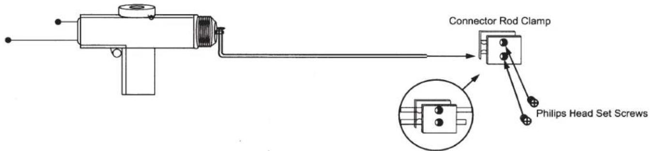
c) Place the CONNECTING ROD ADAPTOR over the existing door button rod as shown and secure it by inserting the 4 x 6 mm Phillips head set screws into the threaded hole and tightening firmly.
d) Manually move the existing door lock button from the locked to the unlocked position and check that the attached mechanism moves smoothly and the plunger on the POWER LOCK MECHANISM extends and retracts.
e) Tighten any loose screws.
f) Repeat the procedure for all remaining doors.
CONNECTION METHODS
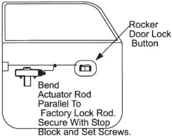
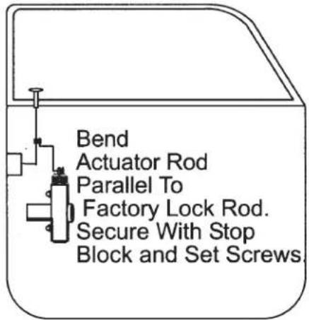
MOUNTING SUPPORT STRAP METHOD

DIRECT TO DOOR FRAME MOUNTING

WIRING
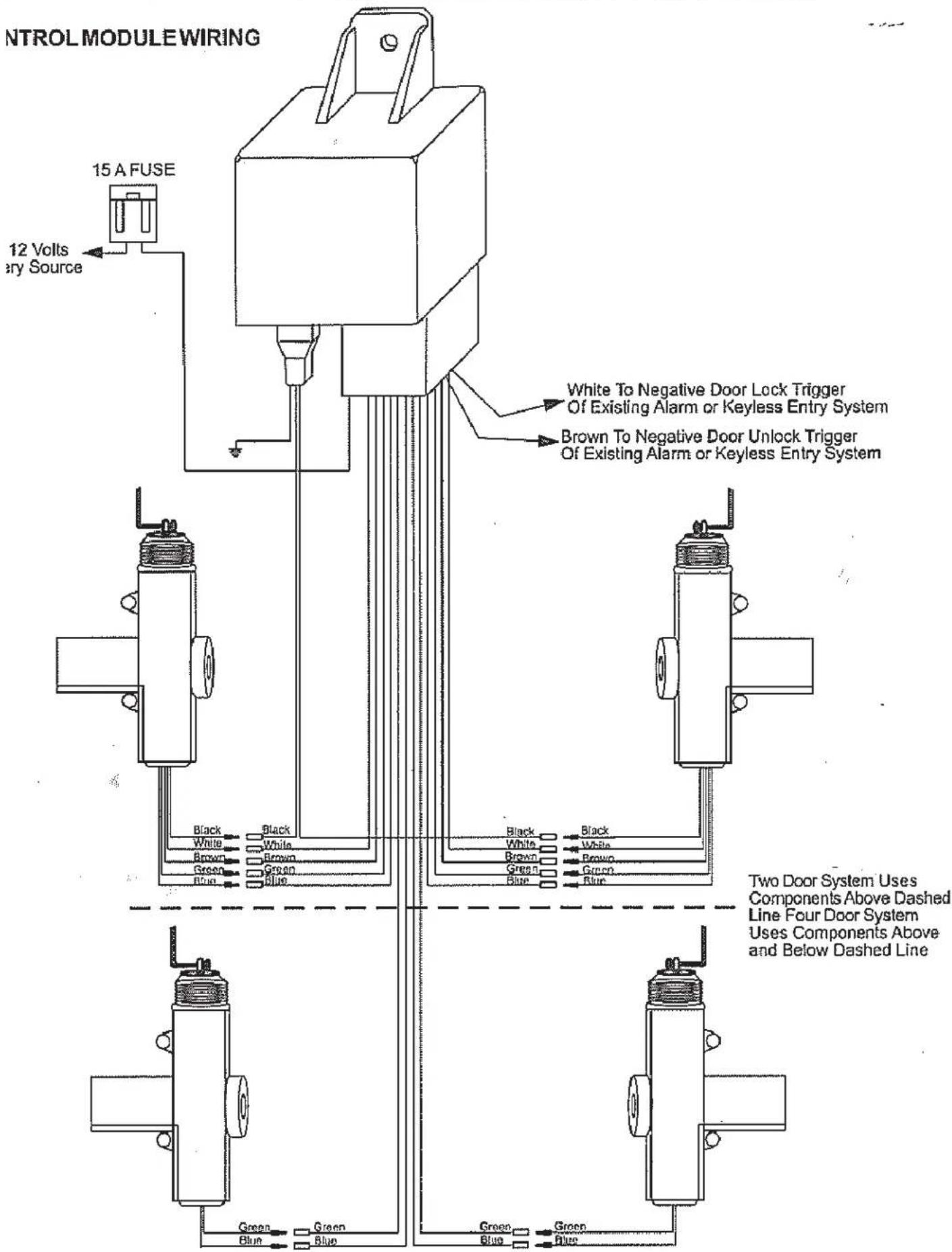
- Plug the five wires in each front door into the matching color wires on the POWER LOCK MECHANISMS.
- Plug the two wires in each rear door into the matching color wires on the POWER LOCK MECHANISMS.
- Secure the BLACK wire on the CONTROL MODULE to a grounded metal part of the vehicle.
- Connect the RED FUSED WIRE on the CONTROL MODULE to a CONSTANT - ON (always live) +12 volt battery source at a fuseblock that is rated for at least 20 amps.
TESTING
NOTE: Roll down the driver's door window.
- Close all doors except the driver's door. Check that all doors are unlocked.
- Close the driver's door and lock it using the door lock key. All doors must lock automatically at the same time.
- Unlock the driver's door using the key and check that all doors unlock at the same time.
- Push the driver's door lock button down and check that all door buttons go down.
- Repeat steps 1, 2, and 3 using the passenger's door.
NOTE: On the 4-Door lock systems, only the two front doors control the system. (Locking the rear doors will not lock the front doors but locking either front door will lock all other doors.) - Once the system is tested, replace the door panels and re-test the system.
REVERSE WIRING FOR 2 DOORS & 4 DOORS
NOTE: When the power door locking mechanisms are wired as shown in the manual, the plunger will extend when the door signals "UNLOCK" and will retract when the door signals "LOCK". In some installations it may be necessary to mount the plunger mechanism in such a position that reversed actuation is required (see Reverse Wiring).
REVERSE WIRING
In order to make the plunger retract when the door signals "UNLOCK" and extend when it signals "LOCK", reverse the wiring as follows:
- For rear doors, reverse the "BLUE" and "GREEN" wires.
- For front doors, reverse the "BLUE" with the "GREEN" wires; and reverse the "BROWN" with the "WHITE" wires. Connect BLACK in all cases.
NOTE: You do not have to reverse wire all the plungers, only one can be reversed wired if desired.
REMOTE CONTROL INPUTS
Negative Trigger: White and Brown, two additional short leads, can be connected to an existing alarm or keyless entry system that switches ground to lock & unlock the doors.
Brown Wire: = - Unlock Input
White Wire: = - Lock Input
CONNECTOR ROD CLAMP DETAIL
10 Audiovox Electronics Corp., 150 Marcus Blvd., Hauppauge, NY, 11788
128-8898
PRODUCT REGISTRATION
Thank you for purchasing an Audiovox product. We pride ourselves on the quality and reliability of all our electronic products but if you ever need service or have a question, our customer service staff stands ready to help. Contact us at www.audiovox.com
√PURCHASE REGISTRATION: Registering On-line will allow us to contact you in the unlikely event a safety notification is required under the Federal Consumer Safety Act.

AUDIOVOX· ELECTRONICS CORP.
Register Online at: WWW.AUDIOVOX.COM
Click on Product Registration and Fill Out the Brief Questionnaire
POWER ACCESSORIES 12 MONTH WARRANTY
Applies to Power Accessories: door lock, windows, trunk release, headlight control, and rear window defogger
AUDIOVOX ELECTRONICS CORPORATION (the Company herein) warrants the ORIGINAL PURCHASER of this POWER ACCESSORY that should this product under normal use and conditions, be proven defective in material or workmanship within 12 MONTHS FROM THE DATE OF ORIGINAL PURCHASE, such defect(s) will be repaired or replaced (at the Company's option) without charge for parts or labor directly related to repairs of the defect(s).
If warranty service is required, please use the exclusive TRAVELER'S WARRANTY SERVICE.
Simply call toll free to our control office for reference to the authorized Warranty Station in your area to obtain an authorization number. No repairs or replacement will be made without a valid authorization number.
Call Toll Free: 1-(800) 645-4994 Traveler Warranty Department
To obtain repair or replacement within the terms of this Warranty, the product is to be delivered with proof of Warranty coverage (e.g. dated bill of sale), authorization number, specification of defect(s), transportation prepaid, to an approved warranty station. This warranty is valid for the original purchaser only and may not be transferred.
This Warranty does not cover batteries, nor extend to damage to the vehicle electrical system. This Warranty does not apply to any product or part thereof which, in the opinion of the Company, has been damaged through alteration, serial number defacement, improper installation, mishandling, misuse, neglect, accident.
This Warranty is in lieu of all other express warranties or liabilities. ANY IMPLIED WARRANTIES, INCLUDING ANY IMPLIED WARRANTY OF MERCHANTABILITY, SHALL BE LIMITED TO THE DURATION OF THIS WRITTEN WARRANTY. IN NO CASE SHALL THE COMPANY BE LIABLE FOR ANY CONSEQUENTIAL OR INCIDENTAL DAMAGES FOR BREACH OF THIS OR ANY OTHER WARRANTY, EXPRESS OR IMPLIED, WHATSOEVER. No person or representative is authorized to assume for the Company any liability other than expressed herein in connection with the sale of this product.
The Company does not warrant that this product cannot be compromised or circumvented. THE EXTENT OF THE COMPANY'S LIABILITY UNDER THIS WARRANTY IS LIMITED TO THE REPAIR OR REPLACEMENT PROVIDED ABOVE AND, IN NO EVENT, SHALL THE COMPANY'S LIABILITY EXCEED THE PURCHASE PRICE PAID BY THE PURCHASER FOR THE PRODUCT.
Some countries, states or provinces do not allow limitations on how long an implied warranty lasts or the exclusion or limitation of incidental or consequential damage so the above limitations or exclusions may not apply to you. This Warranty gives you specific legal rights and you may also have other rights, which vary depending on local law.
TRAVELER'S WARRANTY DEPARTMENT • AUDIOVOX ELECTRONICS CORPORATION •150 MARCUS BLVD. •HAUPPAUGE, NEW YORK 11788
Form No. 128-6155



- PREPARING FOR INSTALLATION
- CONTROL MODULE MOUNTING & WIRE ROUTING
- POWER LOCK MECHANISM MOUNTING
- CONNECTION OF POWER DOOR LOCK MECHANISM TO DOOR LOCK
- DIRECT TO DOOR FRAME MOUNTING
- WIRING
- TESTING
- REVERSE WIRING FOR 2 DOORS & 4 DOORS
- REVERSE WIRING
- REMOTE CONTROL INPUTS
- CONNECTOR ROD CLAMP DETAIL
- PRODUCT REGISTRATION
- REGISTER ONLINE AT: WWW.AUDIOVOX.COM
- POWER ACCESSORIES 12 MONTH WARRANTY
Brand : AUDIOVOX
Model : PRO-PDL-25
Category : Remote control