DX-DRTVM114 - Wall mount Dynex - Free user manual and instructions
Find the device manual for free DX-DRTVM114 Dynex in PDF.


| Product Type | Wall Mount |
| Compatible TV Sizes | 32" to 55" |
| Maximum Weight Capacity | 60 lbs (27 kg) |
| VESA Compatibility | 100x100mm to 400x400mm |
| Tilt Range | +/- 15 degrees |
| Swivel Range | +/- 5 degrees |
| Rotation | 0 degrees (fixed) |
| Material | Heavy-duty steel |
| Finish | Black powder coat |
| Dimensions (H x W x D) | 15.7 x 12.6 x 2.4 inches |
| Weight | 6.6 lbs (3 kg) |
| Profile to Wall | 1.5 inches (low profile) |
| Cable Management | Yes, includes cable clips |
| Included Hardware | Mounting bolts, spacers, concrete anchors, and template |
| Installation | Drilling required; template included |
| Safety Certification | UL listed, tested to hold up to 60 lbs |
| Warranty | 1 year limited warranty |
| Country of Origin | China |
| Mounting Type | Fixed to wall, tilt and swivel capability |
Frequently Asked Questions - DX-DRTVM114 Dynex
User questions about DX-DRTVM114 Dynex
0 question about this device. Answer the ones you know or ask your own.
Ask a new question about this device
Download the instructions for your Wall mount in PDF format for free! Find your manual DX-DRTVM114 - Dynex and take your electronic device back in hand. On this page are published all the documents necessary for the use of your device. DX-DRTVM114 by Dynex.
USER MANUAL DX-DRTVM114 Dynex
Low-Profile TV Wall Mount

natural_image
Technical line drawing of a metal shelving unit with vertical supports and mounting brackets (no text or symbols)

For either wood-stud or concrete wall installations
Safety information and specifications . . .2
Tools needed....3
Package contents ....3
Installation instructions....5
Safety information and specifications

natural_image
Gray triangular warning symbol with black exclamation mark (no text or numbers)IMPORTANT SAFETY INSTRUCTIONS - SAVE THESE INSTRUCTIONS
CAUTION: Do not use this product for any purpose not explicitly specified by Dynex.
Maximum TV weight: 120 lbs. (54.4 kg)
Screen size: 37 in. to 70 in. diagonal
Overall dimensions (H × W):
$$ 3 4 \times 6. 5 \times 2. 5 \text { in. } (8 6. 4 \times 1 6. 5 \times 6. 4 \text { cm }) $$
Wall-mount weight: 7.5 lbs. (3.4 kg)
We're here for you
www.dynexproducts.com
For customer service, call:
1-800-305-2204 (U.S. and Canada) or 01-800-926-3020
(Mexico)
Improper installation may cause property damage or personal injury. If you do not understand these directions, or have doubts about the safety of the installation, contact Customer Service or call a qualified contractor. Dynex is not responsible for damage or injury caused by incorrect installation or use.
The weight of your TV must not exceed 120 lbs. (54.4 kg). The wall must be capable of supporting five times the weight of your TV and wall mount combined.
This product contains small items that could be a choking hazard if swallowed. Keep these items away from young children!

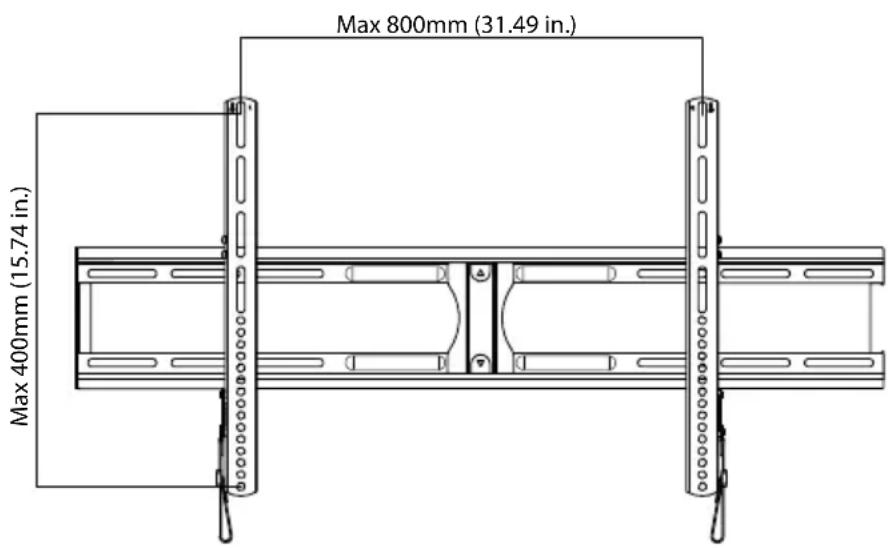
Maximum VESA pattern
Tools needed
You will need the following tools to assemble your new TV wall mount:

Package contents
Make sure that you have all the hardware necessary to assemble your new TV wall mount:
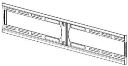
A Wall Plate (1)
C Right TV Bracket (1)
B Left TV Bracket (1)
D Wall plate template (1)
A
natural_image
Technical line drawing of a structural frame with notches and supports (no text or symbols)B

C

D

flowchart
graph TD
    A["Reaction Condition"] --> B["Reagents: Reagent 1, Reagent 2, Reagent 3"]
    B --> C{Reactions: Reagents: Reagent 1, Reagent 2, Reagent 3}
    C --> D["Products: Products 1, 2, 3"]
    D --> E["Quality Check: Reagent 1, Reagent 2, Reagent 3"]
    E --> F["Output: Product 1, Product 2, Product 3"]
TV Hardware Bag
| Label | Hardware Qty. | |
| E |  M4 × 12 mm screw M4 × 12 mm screw | 4 |
| F | _ZW23] M4 × 30 mm screw | 4 |
| G | 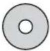 M4/M5 washer M4/M5 washer | 8 |
| H | 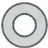 M6/M8 washer M6/M8 washer | 4 |
| I |  M4/M5 spacers M4/M5 spacers | 4 |
| J | 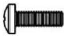 M5 × 12 mm screw M5 × 12 mm screw | 4 |
| K |  M5 × 30 mm screw M5 × 30 mm screw | 4 |
| L |  M6 × 12 mm screw M6 × 12 mm screw | 4 |
| M |  M6 × 20 mm screw M6 × 20 mm screw | 4 |
| Label | Hardware Qty. | |
| N |  M6 × 35 mm screw M6 × 35 mm screw | 4 |
| O |  M8 × 16 mm screw M8 × 16 mm screw | 4 |
| P |  M8 × 40 mm screw M8 × 40 mm screw | 4 |
| Q |  M8 × 60 mm screw M8 × 60 mm screw | 4 |
| R |  M6/M8 spacers M6/M8 spacers | 4 |
| S | 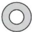 Lag bolt washer Lag bolt washer | 4 |
| T | 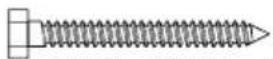 5/16" × 2 3/4" lag bolt 5/16" × 2 3/4" lag bolt | 4 |
| U |  Concrete anchor Concrete anchor | 4 |
Installation instructions
STEP 1- Determine whether your TV has a flat back or an irregular or obstructed back
1 Carefully place your TV screen face-down on a cushioned, clean surface to protect the screen from damages and scratches.
2 If your TV has a table-top stand attached, remove the stand. See the documentation that came with your TV for instructions.
3 Temporarily lay the TV brackets (B and C) on the back of your TV.
4 Align the screw holes in the TV brackets with the mounting screw holes on your TV.
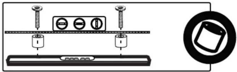
5 Identify which type of back your TV may have:
- Flat back: The brackets lay flush against the back of your TV and do not block any jacks. You do not need spacers when assembling the wall mount.

- Obstructed back: The brackets block one or more of the jacks on the back of your TV. You will need spacers when assembling the wall mount.
natural_image
Diagram showing screw installation components including a battery, three circular components, and a rectangular base with a circular inset (no text or symbols)- Irregularly-shaped back: There is a gap between a bracket and some part of the back of your TV. You will need spacers when assembling the wall mount.
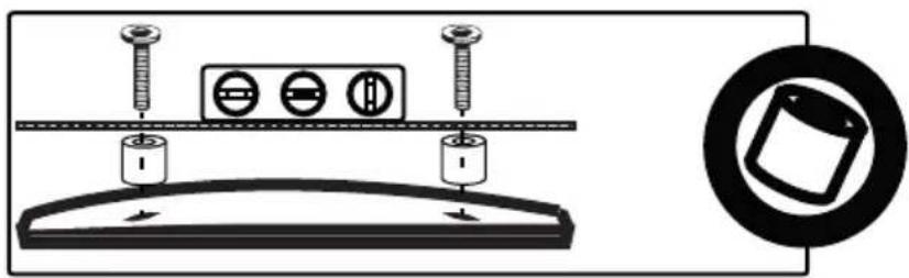
6 Remove the TV brackets.
STEP 2 - Select screws, washers, and spacers
1 Select the hardware for your TV (screws, washers, and spacers). A limited number of TVs come with mounting hardware included. (If there are screws that came with the TV, they are almost always in the holes on the back of the TV.) If you don't know the correct length of the mounting screws your TV requires, test various sizes by hand threading the screws.
Select one of the following types of screws:
Flat back Obstructed back
| M4 × 12 mm screws (E) | M4 × 30 mm screws (F) |
| M5 × 12 mm screws (J) | M5 × 30 mm screws (K) |
| M6 × 12 mm screws (L) | M6 × 35 mm screws (N) |
| M6 × 20 mm screws (M) | M8 × 40 mm screws (P) |
| M8 × 16 mm screws (O) | M8 × 60mm screws (Q) |
Select from the following washers:
M4/M5 washer (G) M6/M8 washer (H)
For an irregular or obstructed TV back, use the following spacers:
M4/M5 spacer (I) M6 /M8 spacer (R)

CAUTION: To avoid potential personal injuries and property damage, make sure that there are adequate threads to secure the brackets to your TV. If you encounter resistance, stop immediately and contact customer service. Use the shortest screw and spacer combination to accommodate your TV. Using hardware that is too long may damage your TV. However, using a screw that is too short may cause your TV to fall from the mount.
Note: If you plan to use a 5^ tilt with a larger TV ( 42^+ ), we suggest using spacers with the mounting brackets so that the bottom of the TV does not touch the wall.
2 Remove the screws.
3 For a flat back TV, go to "STEP 3 - Option 1: Attaching the mounting hardware to TVs with a flat back" on page 7.
-OR-
For an irregular or obstructed back, go to "STEP 3 - Option 2: Attaching the mounting hardware to TVs with irregular or obstructed backs" on page 8.
STEP 3 - Option 1: Attaching the mounting hardware to TVs with a flat back
Note: If you plan to use a 5° tilt with a larger TV (42" +), we suggest using spacers with the mounting brackets so that the bottom of the TV does not touch the wall.
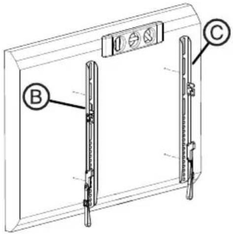
1 Align the left and right TV brackets (B and C) with the screw holes on the back of the TV. Make sure that the brackets are level.
2 Install washers (G or H), and screws (E, J, L, M, or O) into the holes in the back of the TV.
3 Tighten the screws until they are snug against the TV brackets. Do not over tighten.

You'll need
Screws
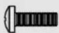
E (4)
or

L (4)

J(4)
or
or

M (4)
Washers
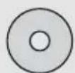
G (4)
or

H (4)
or

O (4)

Level
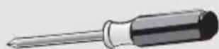
Phillips screwdriver

natural_image
Two identical mechanical components with flanges and a handle, shown side by side (no text or symbols visible)B and C TV brackets
STEP 3 - Option 2: Attaching the mounting hardware to TVs with irregular or obstructed backs
Note: If you plan to use a 5° tilt with a larger TV (42" +), we suggest using spacers with the mounting brackets so that the bottom of the TV does not touch the wall.
1 Align the left and right TV brackets (B and C) with the screw holes on the back of the TV. Make sure that the brackets are level.
2 Place spacers (I or R) behind the TV brackets. If you are using M4/M5 washers (G), place them between the spacers and TV brackets and over the holes in the TV brackets. If you are using M6/M8 washers (H), place them over the holes in the TV brackets. Insert screws (F, K, N, P, or Q) through the washers, TV brackets, and spacers.
3 Tighten the screws until they are snug against the TV brackets. Do not over tighten.

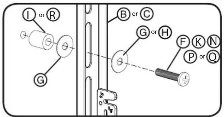
You'll need

STEP 4 - Attaching the tilt brackets
Note: If you plan to use a 5° tilt with a larger TV (42" +), we suggest using spacers with the mounting brackets so that the bottom of the TV does not touch the wall.
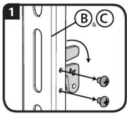
1 Remove the screws holding the tilt brackets to the TV brackets (B and C).
2 Align the tilt bracket so that the shows on the bracket for a 5° tilt.
-OR-
Align the tilt bracket so that the shows on the bracket for a 0° tilt.
3 Do the same to the other TV bracket.
4 Replace the screws and tighten firmly.
Option 1: -5^ Tilt
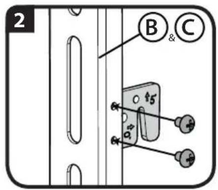
Option 2: No Tilt (0°)


You'll need

Phillips screwdriver
STEP 5 - Determine wall-mount location
Notes:
- For more detailed information on determining where to drill your holes, visit our online height-finder at: http://mf1.bestbuy.selectionassistant.com/index.php/heightfinder
- Your TV should be high enough so your eyes are level with the middle of the screen. Normally, 40 to 60 inches from the ground.
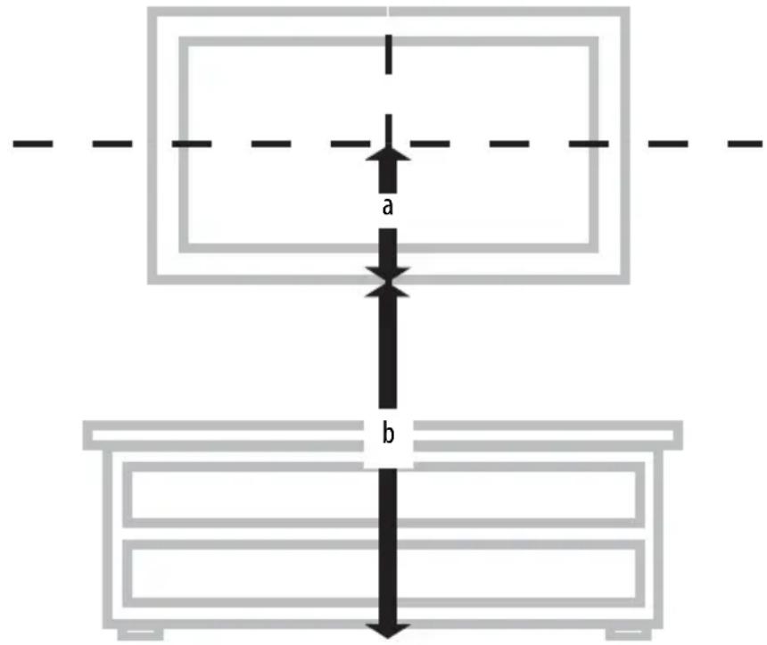
The center of your TV will match the center of the wall plate (A). Before you drill holes in the wall:
1 Measure the distance from the bottom of your TV to the middle (half of the height of the TV). This is measurement a.
2 Measure the distance from the floor to where you want the bottom of the TV to be placed on the wall. Keep in mind that the bottom of the TV should be placed above any furniture (such as entertainment centers or TV stands). The TV should also be above items placed on top of the furniture (like a Blu-ray player or cable box). This measurement is b.
3 Add a + b . The total measurement is the height where you want the center of the wall plate to be on the wall.
4 Use a pencil to mark this spot on the wall.
You'll need
Measuring tape
Pencil
STEP 6 - Option 1: Installing on a wood stud wall
Note: Any drywall covering the wall must not exceed 5/8" (16 mm).
1 Locate the stud. Verify the center of the stud* with an edge-to-edge stud finder.
2 Align the wall plate template (D) at the height you determined in the previous step, make sure that it is level, then tape it to the wall. Use a pencil to mark the lag bolt hole locations (4) on the stud centers.
3 Drill pilot holes to a depth of 3 in. (75 mm) using a 7/32 in. (5.5 mm) diameter drill bit. Remove the wall plate template.
4 Align the wall plate (A) with the pilot holes, insert the lag bolts (T) through the lag bolt washers (S), then through the holes in the wall plate. Tighten the lag bolts only until they are firm against the wall plate.

CAUTION: Avoid potential injuries or property damage! DO NOT over-tighten the lag bolts (T).
- Minimum wood stud size: common 51 x 102 mm (2 x 4 in.) nominal 38 x 89 mm (11/2 x 31/2 in.).
- Minimum spacing between horizontal fasteners cannot be less than 16 in.

flowchart
graph TD
    A["Step 1: Sensor input"] --> B["Step 2: Display panel"]
    B --> C["Step 3: Drill tool in 75 mm"]
    C --> D["Step 4: Tool assembly with labeled sections A, S, T"]
    style A fill:#f9f,stroke:#333
    style B fill:#ccf,stroke:#333
    style C fill:#cfc,stroke:#333
    style D fill:#fcc,stroke:#333
You'll need

natural_image
Technical line drawing of a structural panel or enclosure with no visible text or symbolsWall plate (A)

Pencil
Drill

Edge-to edge
stud finder

7/32" wood drill bit

1/2" socket wrench

Wall plate template (D)

S (4)
T (4)

Level

Tape
STEP 6 - Option 2: Installing on a solid concrete or concrete block wall\*
CAUTION: To prevent property damage or personal injury, never drill into mortar between blocks. Mount wall plate directly onto the concrete surface.
1 Align the wall plate template (D) at the height you determined in the previous step, make sure that it is level, then tape it to the wall. Use a pencil to mark the lag bolt hole locations (4).
2 Drill pilot holes to a depth of 3 in. (75 mm) using a 3/8 in. (10 mm) diameter masonry drill bit. Remove the template.
3 Insert the concrete wall anchors (U) into the pilot holes and use a hammer to make sure the anchors are flush with the concrete surface.
4 Align the wall plate (A) with the anchors, insert the lag bolts (T) through the lag bolt washers (S), then through the holes in the wall plate. Tighten the lag bolts only until they are firm against the wall plate.
CAUTION: Avoid potential injuries or property damage! DO NOT over-tighten the lag bolts (T).
* Minimum solid concrete thickness: 8 in. (203mm).
* Minimum concrete block size: 8 x 8 x 16 in. (203 x 203 x 406 mm).
The minimum distance between the top two fasteners cannot be less than 16 in.

flowchart
graph TD
    A["1: 3 in. (75 mm)"] --> B["2"]
    B --> C["3: U"]
    C --> D["4: U, A, S, T"]
You'll need
natural_image
Technical line drawing of a structural panel or enclosure with internal components (no text or symbols)Wall plate (A)

Wall plate template (D)
Pencil

S (4)
Edge-to edge
stud finder

U (4)

Drill

T (4)

3/8" masonry drill bit

1/2" socket wrench

Level

Tape
STEP 7 - Mounting the TV to the wall plate
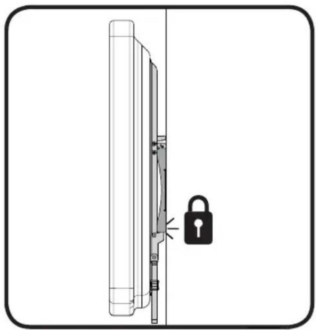
1 Place the TV brackets (B and C) into the slotted flanges of the wall plate (A).
2 Push the bottom of the TV toward the wall until the latch mechanism clicks into place.

HEAVY! You will need assistance with this step.

natural_image
Diagram of a door lock assembly with a lock icon and handle (no text or symbols)Removing the TV from the wall plate
1 Grasp the TV by the bottom edge, then pull down on the locking cords and pull the bottom of the TV out from the wall.
2 Release the locking cords and lift the top of the TV from the wall bracket.

HEAVY! You will need assistance with this step.

DYNEX™
www.dynexproducts.com 1-800-305-2204 (U.S. and Canada) or 01-800-926-3020 (Mexico)
Distributed by Best Buy Purchasing, LLC
7601 Penn Ave. South, Richfield, MN 55423 U.S.A.
© 2013 BBY Solutions, Inc. All rights reserved.
DYNEX is a trademark of BBY Solutions, Inc. Registered in some countries. All other products and
brand names are trademarks of their respective owners.
6907-002052 00
- Low-Profile TV Wall Mount
- Safety information and specifications
- Tools needed
- Package contents
- Installation instructions
- STEP 1- Determine whether your TV has a flat back or an irregular or obstructed back
- STEP 2 - Select screws, washers, and spacers
- STEP 3 - Option 1: Attaching the mounting hardware to TVs with a flat back
- You'll need
- STEP 3 - Option 2: Attaching the mounting hardware to TVs with irregular or obstructed backs
- STEP 4 - Attaching the tilt brackets
- STEP 5 - Determine wall-mount location
- Notes:
- STEP 6 - Option 1: Installing on a wood stud wall
- STEP 6 - Option 2: Installing on a solid concrete or concrete block wall\*
- STEP 7 - Mounting the TV to the wall plate
- Removing the TV from the wall plate
- DYNEX™
Brand : Dynex
Model : DX-DRTVM114
Category : Wall mount