
LiveSight Thru-Hull - Marine Radar SIMRAD - Free user manual and instructions
Find the device manual for free LiveSight Thru-Hull SIMRAD in PDF.

User questions about LiveSight Thru-Hull SIMRAD
0 question about this device. Answer the ones you know or ask your own.
Ask a new question about this device
Download the instructions for your Marine Radar in PDF format for free! Find your manual LiveSight Thru-Hull - SIMRAD and take your electronic device back in hand. On this page are published all the documents necessary for the use of your device. LiveSight Thru-Hull by SIMRAD.
USER MANUAL LiveSight Thru-Hull SIMRAD
Compliance statements
Europe
Navico declares under our sole responsibility that the product conforms with the requirements of:
• CF under EMC Directive 2014/30/EU
United States of America
Note: The user is cautioned that any changes or modifications not expressly approved by the party responsible for compliance could void the user's authority to operate the equipment.
Australia and New Zealand
Navico declares under our sole responsibility that the product conforms with the requirements of:
• level 2 devices of the Radiocommunications
(Electromagnetic Compatibility) standard 2017
Declarations
The relevant Declaration of Conformity is available on the following websites:
• www.lowrance.com
• www.simrad-yachting.com
Address
Navico Logistics Europe B.V.
Laan van Europa 450
3317 DB Dordrecht
The Netherlands
Required tools

natural_image
Collection of industrial tools and components including a drill, screwdriver, and clamp (no text or labels visible)A Drill
B Drill bits 9 mm (3/8")
C Hole saw 35 mm (1 3/8")
D Heat gun
E Sandpaper
F Marine grade above
or below waterline sealant
G 13 mm and 50 mm size wrench
H Band saw or table saw
LOWRANCE
SIMRAD
LiveSight thru-hull transducer
Installation Guide
natural_image
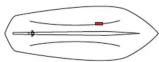
Line drawing of a ship's hull with a barcode bar below (no text or symbols on the diagram itself)Technical specifications
The most up-to-date specifications are available at the product web site.
| Environmental | |
| Water temperature for operation | 0°C to +35°C(32°F to +95°F) |
| Storage temperature | -30°C to +70°C(-22°F to +158°F) |
| Physical | |
| Weight | 2.3 kg (Thru hull without fairing block)0.84 kg (fairing block) |
| Cable length | 7,6 m (25 ft) |
| Hull requirements | |
| Dead rise angle | 0 - 25° |
| Max hull thickness | 5 cm (2") |
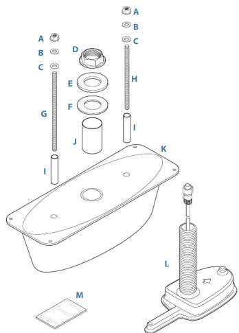
Parts included
A M8-1.25, flange nut, 316 ss (x2)
B M8 washer, 316 stainless steel (x2)
C M8 washer, nylon, M8, 8.5mm ID, 16mm OD (x2)
D Flange nut, M33
E M33 washer, 316 stainless steel
F M33 fairing isolator washer, nylon
G M8-1.25 x 185 mm stud, 316 ss
H M8-1.25 x 150 mm, stud, 316 ss
Isolator sleeve, M8 (x2)
J Isolator sleeve, M33
K Fairing block
L LiveSight thru-hull transducer
M Documentation pack
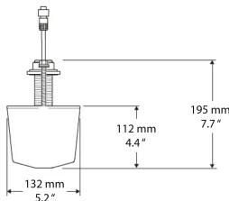
Dimensions

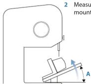
The Fairing block
The transducer must be mounted as parallel to the water surface as possible.
For hulls with a dead rise angle, the fairing block should be used to compensate for the dead rise angle.
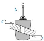
A Vessels with a dead rise angle >10^
B Vessels with dead rise angle < 10^
C Minimum fairing thickness = 12 mm (0.5")
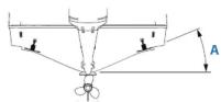
Mounting location (guidelines only)
The transducer will not work while it is out of the water, ensure that it is in contact with the water at all speeds. The transducer must be mounted in an area that provides smooth non-turbulent water flow, unobstructed by keel or propeller shafts. On single-drive vessels, if the propeller is turning clockwise, mount the transducer on the starboard side. If the propeller is turning counterclockwise mount the transducer on the port side. On twin-drive vessels, mount the transducer between the drives.
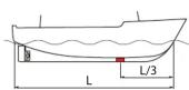
Displacement hull powerboat

Stepped hull
Mount just in front of the first step and and between the centerline and the first set of lifting strakes.
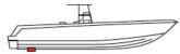

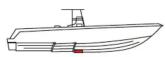
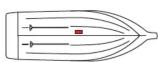
Planing hull, outboard and stern-drive
Mount well aft, and between the centerline and the first set of lifting strakes.

Planing hull, inboard
Mount well ahead of the propeller(s) and shaft(s), and between the centerline and the first set of lifting strakes.
Full keel sailboat
Mount in front of the keel at the point of minimum deadrise angle and close to the centerline.
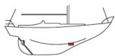
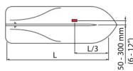
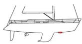
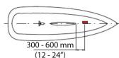
Fin keel sailboat
Mount to the side of the centerline and 300 - 600 mm (12 - 24") in front of the keel.
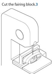
Cutting the fairing block

1 Attach the fairing block to a piece of wood using wood screws (not included).
Installation
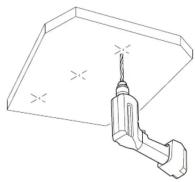
1 Mark the holes on the outside of the hull using the mounting template.

natural_image
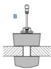
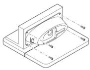
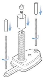
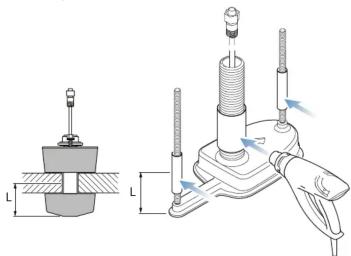
Technical diagram showing a boat with a rotating platform and its side view with a directional arrow (no text or symbols)3 Screw the M8 studs into the transducer. Metal hulls only, install the isolator sleeves over the studs.
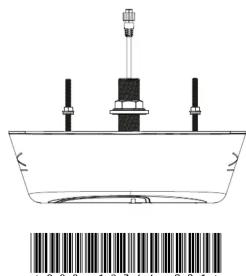
natural_image
Mechanical assembly diagram showing a cylindrical device with three vertical rods and a base, no text or symbols present.5 Use sand paper to remove all burrs and sharp edges to smooth the installation surface.
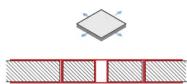
7 Apply marine grade sealant or epoxy to the sanded surfaces and to the mating edges of the fairing block. Install the upper part of the fairing block from the inside of the boat.
Drill the holes.2
4 Metal hulls only, make sure that the isolatorsleeves will cover the contact area between the hull and the studs. Use a heatgun to shrink the isolator sleeves in place.
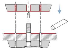
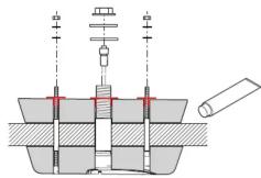
natural_image
Technical illustration of mechanical assembly with two views: top shows a cylindrical component, bottom shows a base with threaded fasteners and a clamp-like tool (no text or symbols)6 Apply marine grade sealant or epoxy to the sanded surfaces and to the mating edges of the fairing block. Push the transducer through the lower part of the fairing block, and press the assembly through the holes in the boat.
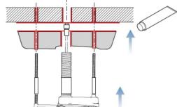
8 Apply marine grade sealant or epoxy in and round the holes of the fairing block. Secure the assembly with the washers and the nuts.
Brand : SIMRAD
Model : LiveSight Thru-Hull
Category : Marine Radar