TXP1.6000D - Receiver Soundstream - Free user manual and instructions
Find the device manual for free TXP1.6000D Soundstream in PDF.


User questions about TXP1.6000D Soundstream
0 question about this device. Answer the ones you know or ask your own.
Ask a new question about this device
Download the instructions for your Receiver in PDF format for free! Find your manual TXP1.6000D - Soundstream and take your electronic device back in hand. On this page are published all the documents necessary for the use of your device. TXP1.6000D by Soundstream.
USER MANUAL TXP1.6000D Soundstream
TXP2.6500D TXP4.3500D TXP1.3500D TXP1.6000D TXP1.12000D TXP1.18000D
Compact Size High Power Amplifier
PLEASE READ THIS MANUAL BEFORE INSTARAGE AND USING AMPLIFIER
Congratulations on your Purchase
Your new high fidelity bridgeborested ammelt an amplifier is designed to deliver maximum enjoyment and years of trouble free service. The quality of the installation may affect the performance and the reliability of your products
Features
Class "D" High Efficiency Mono Block Car Amplifier
● Bridgeable & TRI-Mode Operation.
●Continuity Variable 1200/Octave High Pass & 1200/Octave Low Pass Crossover
●Exterior Variable Exposure for Pass Here Control
- Enhanced Bana Brasil +1318 (R\$50H)
■Silver Plated RGA, Power & Speaker Terminal
●Soft Start & Mating
●Overload Thermal
●Power & Protection Monitor.
●Nass Land Rentals Control 18, 4951
Precautions: Read First!
●The amplifier needs to be installed by an authorised installer
Negative battery terminal must be disconnected before any electrical connections are made. So sure choose a location that provides substantial ventilation for the amplifier. The most preferred locations would be in you can't track, under the front seats or on the back wall of a truck.
- The location chose should provide at least 2° of clearance above the amplifier for adequate
- If the equal or is to be mounted vertically be sure that it is in a place where adequate or
and now along the length of its health controls for recovery.
●NEVER mount the amplifier up side down, this will cause the heat to
amplifier causing thermal shutdown or possible permanent damage
●NEVER mount the amplifier in a location that is subject to direct sunlight or exposed to
Moisture
●Be sure to mount the amplifier to a strong, acid surface which will not give way under the
stress of a sudden soap or accident
●Make sure that the mounting screws will not generate the gas tank. Brake and fuel lines
being to other critical parts of your cat when initiated
■ Ensure that quality rating is used to enhance the safety and performance of your
(2) 求心病
● Warranty must be void if proper installation technique and ceiling is not used.
7
SPECIFICATION
TXP1.12000D
1.300w x 1@ 4-phm Stereo
2.300m x 7 @ 2-ohm Stereo
4.300w x 1 @ 1-ohm Stereo
12.000m MAX Power
THD: +0.3%
Input Sensitivity: 200My-6V
HFE:15.80Hz
1.26:80-30KH
Bass Roost: 0-12dB 50Hz Bass Roost
Working Voltage: 94-10V DC
Distortion Cup Lights
With Remote Controller
Size:8.25" w×2.75" h×7.25" | Size:8.25" w×2.75" h×10.5"
TXP1.18000D
1.800w x 1 @ 4-ohm Stereo
3,600w x 1 @ 2-ohm Stereo
7.000w x 1 @ 1-ohm Stereo
18.000w MAX Power
THD: <0.3%
Input Servit
Input Sensitivity, 2.0dB/s
HPF:13-20H2
LPF:80-20KHz
Bass Boost: 0-12dB 50Hz Bass Boost
Frequency Response: 20-20KHz
S/N: 105dB
Working Voltage: 9V-16V DC
Distortion Clip Lights
With Remote Control
Size: 8.75" w×2.75" h×10.5"
SPECIFICATION
TXP2.65000
400w×2@4-ohm Stereo
700w x 2 @ 2-ohm Stereo
1.250w x 2 @ 1 ohm Stereo
2.500=×1=2-ohm Bridged
6,500—MAX Power
6,300M MAX
THD: <0.3%
Input Sensitivity: 200Mv-6V
HPF:15-1KHz
LPF:50-10KH
Bass Boost: 0-12dB 5GHz Bass Boost
SUN: 10549
310.1056
Working voltage: 9V-16V DC
Distortion Clip Lights
With Remote Controller
Size: 8.25" w×2.75" b×5.75"
TXP4.3500D
140w x 4 @ 4-ohm Stereo
23Swx4@2-ohm Stereo
375w x 4 @ 1 ohm Stereo
700m x 2 @ 2-ohm Bridged
2,500+ MAX Power
3,500 MARS TURS - 0.24
THD: <0.3%
Input Sensitivity: 200Mw-5V
HPF:15-6kHz 12dB
LPF: 50-6KHz 12dB
Bass Boost: 0-12dB
S/N: 10549
SIN: 10,000
Working voltage: 2V-1BV DC
Distortion Clip Lights
Size: 8.25" w×2.75" h×7.25"
(1) 本说明仅供参考。
TXP1.35000
450w x 1 @ 4-ohm Stereo
800=×1=2-ohm Stereo
1.250w x 1 @ Lohm Stereo
2,500—MAX Power
3,500M MAX Power
THD: <0.3%
Input Sensitivity: 200Mv-6V
HPF:15-1KHz
LPF:50-10KH
Bass Report: 0-12dB 50Hz Bass Report
BASY BOOST: 0-12GB 30-12 DAYS BOOST
Frequency Response: 20-20kHz
S/N: 105dB
Working Voltage: 9V-16V DC
Distortion Clip Lights
With Remote Controls
Size: 8.25" w×2.75" h×4.25"
TXP1.6000C
700w x 1 @ 4-ohm Stereo
1.200w x 1 in Z-ohm Stegen
2.350w x 1 @ 1-ohm Stereo
- ОПОУ МАХ РОЧИЯ
6,000 MRC
THD: <0.3%
Input Sensitivity: 200Mv-5V
HPF:15-BCH
LPF:80-20KH;
Bass Boost: 0-12dB 50Hz Bass Boost
Frequency Response: 20-20kHz
5/N:105dB
Working Voltage: 9V-16V DC
Distortion Clip Lights
With Remote Control
Size: 8.25" w x 2.75" h x 5.75"
1
2
INSTALLATION & CONNECTIONS
MOUNTING
- After reading precaution, decide where you are going to install the unit. Also, see Fig. 1.
2 Once the location has been determined, place the amplifier into position. Using a left to
pen of pencil mark the four holes to be drilled for mounting. NEVER use the ampillar as
a template for drilling. It is very easy to damage the amplifier surface in this manner.
- Remove amplifier. Drill four 3.5 min holes into mounting surface, if you want to mount
the amplifier to MOF or wood panel, drill four 3.0 mm diameter holes into mounting surface.
- If possible, test the system to ensure it is operating correctly before final meeting of
the angiter
- Mount the smaller uses the supplied 4-well lapex score.
INPUT CONNECTIONS
This amplifier will accept low level inputs only. Low level in the same as low level. The low
level signal is control through RGA cables. It is preferred to use low level inputs to the
another if the head unit is equipped with the low level output. If not, you can use a "high
"to low converter" available through your local car audio shop.
Correct the low level/line level RCA cable from the head and, or signal processor, to the
the level input on the amplifier. See Fig.2 system wiring diagrams
POWER CONNECTIONS
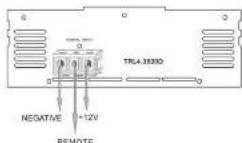
It is important to have good quality power and ground connections. Remember: to complete
an electrical circuit, the ground correction is just as important as the positive power.
connection. Before any power connections are made, disconnect the ground cable at the
Country
When the power supply lead, memory backup lead of ground lead are extended use a time ^1
(AWG5) or larger automotive grade cable which will withstand friction and heat to sale
The following table provides the information in a tabular format:
GND=Connect the proper gauge ground wire to the amplifier 'GND' terminal. Locate the
position on the chessia of the car to which the amplifier is to be grounded. The surface must
to free from any part of the. This can be accomplished with a small grinding bit, sandl
paper of Ave Street. NOTE: Do not ground the arqinder to the 'three of the car. The manes in most cars and trucks is not upunded, to the cheerin (bands). Use Solder or a plampa ring to
respect the ground wire. Pre-drill the prepared chassis to bolt the grounding terminal with
nut, bolt and lick washers. Incurate metal and connector with paint or silicon to prevent
nal and oxidation. Silicon also works great to prevent nuts and beta from working loose in
a harsh environment of an automobile. Open completion of the ground connection, prob
wire or connector and connection, it is a good connection. To provide large noise, it is recommended to ground the hand wall and other optic electronics in the same location.
We believe that our future plans will be a good outlook of the next quarter.
REM = Connect the remote wire (power antennas output) from the head unit to the remote
from an wire of the amplifier. If the head unit is not equipped with a remote antenna output,
As to a web of that is eradicated by the necessary position of this say. It is important to have the email because off the code or away. If the email has been on, the email will now
The ship
12) Helvemil: The consensus company is the only one of the members. Results to
12V-Connector-protein-gauge power who is involved by: Terminal, Hall wire
3
TROUBLE SHOOTING GUIDE
This section provides you with a catalog of amplifier symptoms and their probable causes and solutions. Before you consult the listing, make sure the vehicle's electrical system is working properly by verifying that other electrical items (e.g. headlights, windows, etc.) still function correctly.
| SYM/FOM | PROBABLE SOURCE | SOLUTION |
| RoAudio | Low or N.C. RemoteTurn-off-connectedBlown FusePower lines not connected | Check remove turn-off voltage atamp and head-will |
| Replace with new feed blow fuseCheck boot supports, switches, and pointsCheck ground and battery connections | ||
| Blown or on speakerconnected | Use VDM or DNA to measure speakerstillindependent check speaker wiringconnections | |
| Distorted Audio | Input sensitivity not setpropertyor damaged speaker centres | See adjustment procedure and checkeach step; |
| Interrupt each speaker for damageand repair or reaction suspectedcomponent | ||
| Low turn-on voltage | Refer to head-unit owner's manual | |
| Audio Level Low | Multi circuit on headunit on an. | Check electrical system for lowvoltage;Check ground connection |
| Audio Lamps | Speakers wired with wrongpriority causingconceiling of basesfrequency. | Check yearly of remote fromamplifiers to earb speaker Assisted ifthe system designCheck battery voltage at amplifierduring operation |
| External FuseSlowing | Interlocking at shortcircuit | Refer to electrical installation andcheck power connection step |
| Writing noiseon audio withenging running | Amplifier is picking upadditional spark noise | install an in-line noise filter on thehead unit's power wire. Checkall signal matching switches onregulator for proper operation. Checkall signals, battery voltage, andRCA cables. |
| Teaching noise onaud to withenging running | Amplifier is picking upadditional spark noise | Check RCA audio cable install anin-line noise filter on thehead unit's power wire. Check spark propylene. |
8
ADJUSTMENTS
Set to the 'K.P.F' position when the amplifier is used to drive a wireless-range system. The frequencies below the crossover point will be attenuated at 12dB/octane. Permits adjustment of the crossover frequency, by rotating the knob to select any frequency between 4kHz to 1.2 kHz as the crossover point.
- Set to the "L.P.F" position when the amplifier is used to drive a subcarrier. The frequencies above the crossover point will be attenuated at 12dBectave. Parents adjustment of the crossover frequency, by rotating the knot to select any frequency between 50Hz to 250Hz as the crossover point.
3.5a1 to the "OFF" position when the amplifier will be used for driving full-range speakers. The full frequency band width (20Hz-20KHz) will be output to the speakers without high or low frequency attenuation.
-
Level adjustment The sensitivity adjustment is to allow the amplifier to work with many different brands of head units. In loose input signal to vary between 350 millivolts to 5 volt from the head unit or other signal processor. Start by setting the sensitivity adjustment to be "the 1/2" (200 volts) using a cassette or compact disc that you are taken with "turn on the head unit." The 314 volume is set up to 100 volts, and the "MAX" (200 mV) voltage using a flat head screw drive. Stop turning on the onset of distortion and turn back just a night. The 314 volume setting is now the maximum I volume for the head unit. The goal is to keep the level control to the forward setting yet still have enough signal to drive the amplifier. This is done to prevent over driving the impulse and to keep the power of the current operating system. This important no ever drive speakers will count of circums in this well as cause permanent damage to speaker. Also, if the amplifier itself is over driver, it could be damaged.
-
The "BASS" function can be selected to increase low frequency response output, or decrease frequency response output. The "BASS" function will be working only -OFF or "L.P.F" position.
• The BASS is adjustable from 0–12 dB boost at 50Hz.
7
1 CHANNEL MONO BLOCK CLASS D AMPLIFIER CONNECTION
Install the fuse holder that is less than 2.5 meters from the battery. Remember the fuse is to protect the safety of the air in case of a short. Connect fuse holder to battery but do not install fuse at this time.
This amplifier can operate in one, two or three channel mode. The minimum impedance for
single channel (bridged mono) operation is 4 or 6 ohms. Tri channel power is referred to
stereo and more at the same time. Minimum impedance remains the same to three channels
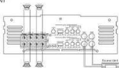
(see the following system as long as proper passive transmitters are used. Correlations and left speaker wire to corresponding spectral output terminals of the amplifier. He sure to
have the positive wine from the speaker connected to the positive speaker terminal of the
amplifier and the negative wire from the speaker must connect with the negative speaker
terminal of the amplifier. Reversing any of these connections will result in the speaker control
moreing out of phase which causes blood cannulation. See Fig.3 Speaker Output Connection
MONO CHANNEL SPEAKER WIRING DIAGRAM
TXP1.3500D/TXP1.6000D/TXP1.12000D/TXP1.18000D
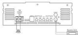
TXP1.35000/TXP1.60000/TXP1.120000/TXP1.180000
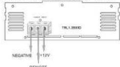
d
2CHANNEL AMPLIFIER WIRING
TXR2 6500D
FRONT
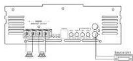
TXP2.6500D
REAR
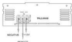
5
4CHANNEL AMPLIFIER WIRING
TXP4:3500D
FRONT
TXP4.3500D
REAR
E
- Congratulations on your Purchase
- Features
- Precautions: Read First!
- SPECIFICATION
- TXP1.12000D
- TXP1.18000D
- TXP2.65000
- TXP4.3500D
- TXP1.35000
- TXP1.6000C
- INSTALLATION & CONNECTIONS
- MOUNTING
- INPUT CONNECTIONS
- POWER CONNECTIONS
- TROUBLE SHOOTING GUIDE
- ADJUSTMENTS
- CHANNEL MONO BLOCK CLASS D AMPLIFIER CONNECTION
- MONO CHANNEL SPEAKER WIRING DIAGRAM
- 2CHANNEL AMPLIFIER WIRING
- 4CHANNEL AMPLIFIER WIRING
Brand : Soundstream
Model : TXP1.6000D
Category : Receiver