B43 - Lawn mower Maruyama - Free user manual and instructions
Find the device manual for free B43 Maruyama in PDF.


| Product Type | Brushcutter |
| Brand | Maruyama |
| Model | B43 |
| Dry Weight (kg) | 8.4 |
| Engine Displacement (cc) | 41.5 |
| Fuel Tank Capacity (L) | 1.0 |
| Carburetor Type | Diaphragm |
| Ignition System | Solid State |
| Spark Plug | NGK BPM6Y (gap 0.6-0.7 mm) |
| Fuel Mixture | 25:1 (gasoline:2-cycle oil) |
| Handle Configuration | Horn Handle |
| Cutting Blade | Metal blade, left-hand rotation |
| Debris Shield | Included, with shield extension |
| Shoulder Harness | Required for metal blade operation |
| Air Filter | Foam element, clean after each use |
| Spark Plug Maintenance Interval | Every 25 hours |
| Gearcase Lubrication Interval | Every 30 hours |
| Idle Speed | 2400-2800 RPM |
| Stop Switch | Slide type (ON/STOP) |
| Choke System | Manual lever |
| Primer Bulb | Yes, for cold starts |
| Engine Type | 2-cycle, air-cooled |
Frequently Asked Questions - B43 Maruyama
User questions about B43 Maruyama
0 question about this device. Answer the ones you know or ask your own.
Ask a new question about this device
Download the instructions for your Lawn mower in PDF format for free! Find your manual B43 - Maruyama and take your electronic device back in hand. On this page are published all the documents necessary for the use of your device. B43 by Maruyama.
USER MANUAL B43 Maruyama
natural_image
Line drawing of a mechanical device with articulated arm and head assembly (no text or symbols)The POWER in Outdoor Power
- Read and understand this Manual before using the brushcutter. Be thoroughly familiar with the proper use of the brushcutter.
- Never allow children to operate the brushcutter. it is not a toy. Never allow adults to operate the unit without first reading the Instruction Manual.
- Become familiar with the controls and know how to stop the engine quickly.
- ALWAYS WEAR SAFETY GLASSES or other suitable eye protection, and hearing protection.
- Keep the area of operation clear of all persons, particularly small children and pets.
- Never operate a brushcutter when you are fatigued.
- Never operate without proper shields or other protective safety devices in place.
- Dress properly; do not wear loose clothing or jewelry. They can be caught in moving parts. Always wear substantial footwear, long pants and long sleeved shirt.
- Gasoline is highly flammable; handle it carefully. Fill the fuel tank with the correct mixture of gasoline and oil before trying to start the engine.
- Use an approved fuel container to store the gasoline/oil mixture.
- Do not fill the tank when the engine is hot or running.
- Do not smoke while handling gasoline.
- Fill the fuel tank outdoors and up to about 10mm from the top of the tank, not the top of the filler neck.
- Wipe any spilled gasoline before starting the engine.
- Always be sure of your footing; keep a firm hold of the handles with both hands, and walk, never run.
- Use the right tool for the job. Do not use the brushcutter for any job that is not recommended by the manufacturer.
- Keep all fasteners tight to be sure the brushcutter is in safe working condition. Follow the maintenance instructions provided on page US-6 of this manual.
- Do not put hands or feet near or under the rotating parts.
- Keep clear at all times.
- If the brushcutter should start to vibrate abnormally, stop the engine and check immediately for the cause. Vibration is generally a warning of trouble.
- Do not trim too close to the ground in order to avoid hitting small stones or other debris. Avoid using the brush-cutter near rocks, gravel, stones and similar matter.
- Use the brushcutter only in daylight or good artificial light.
- Shut off the engine and be certain the cutting blade has completely stopped rotating before inverting the machine.
SPECIFICATIONS
| MODEL | B43 | B43R | BF43R | B50R | BF50R |
| Dry Weight (kg) | 8.4 | 8.5 | 8.6 | 8.5 | 8.6 |
| Handle Configuration | Horn Handle | ||||
| Engine Displacement (cc) | 41.5 | 41.5 | 41.5 | 49.9 | 49.9 |
| Fuel Tank Capacity ( ) | 1.0 | ||||
| Carburetor | Diaphragm Type | ||||
| Ignition | Solid State System | ||||
| Spark Plug | NGK BPM6Y Set Gap 0,6 - 0,7 mm | ||||
| Fuel Mixture | Use Only Non - Leaded Regular Gasoline.2 - Cycle Oil Mix 25:1 Ratio Must Be Approved For Air - Cooled Engines. | ||||
Product Description
B43, B43R, BF43R, B50R, BF50R
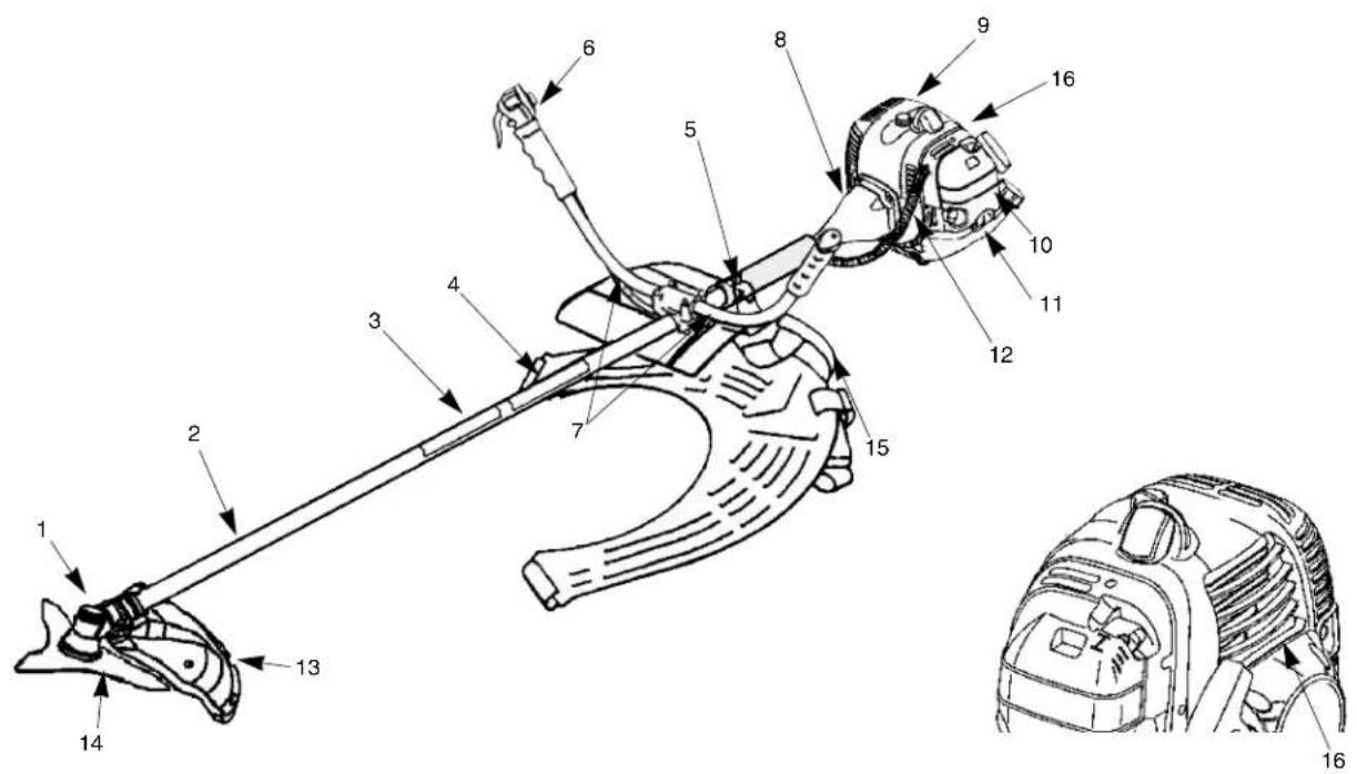
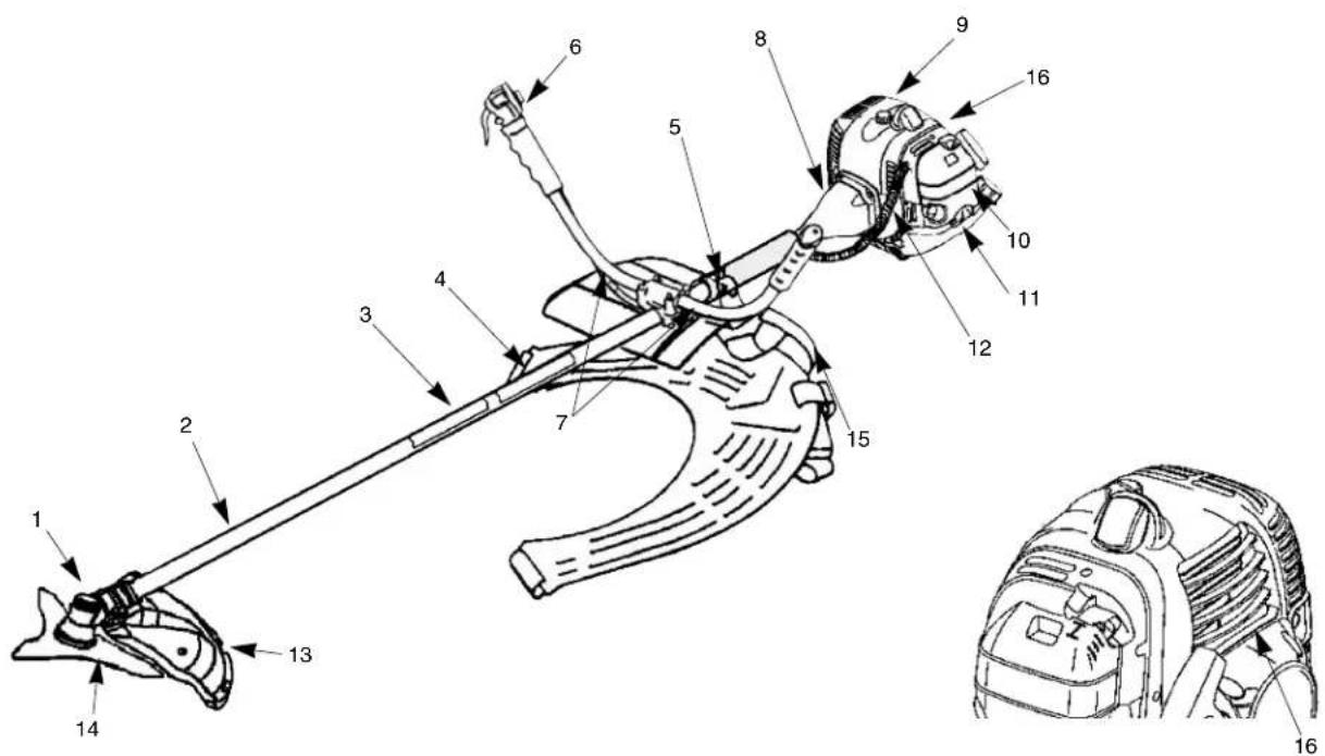
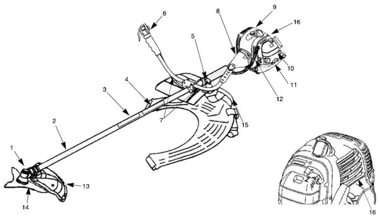
- Gearcase
- Shaft Assembly
- Safety Decal
- Model Name
- Attachment Ring for Shoulder Harness
- Throttle Trigger and Stop Switch
- Handlebar
-
Clutch Drum Housing
-
Engine
- Air Filter
- Fuel Tank
- Throttle Cable and Stop Switch Wires
- Debris Shield
- Cutting Blade
- Shoulder Harness
- Serial Number (on rear of engine)
ASSEMBLY INSTRUCTIONS
ENGINE AND DRIVESHAFT ASSEMBLY
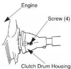
Attach the clutch drum housing to the engine using the four screws.
HANDLEBAR
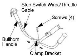
- Loosen the four screws on the top of the clamp bracket.
- Insert the left and right handle bars into the clamp bracket.
CONNECTING THROTTLE CABLE AND STOP SWITCH WIRES
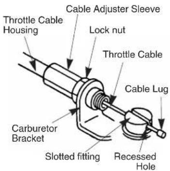
- Insert the throttle cable through the cable adjuster sleeve.
- Position the slotted fitting on the carburetor so the recessed hole for the lug is away from the cable adjuster sleeve.
- Rotate the carburetor throttle cam and slip the throttle cable through the slot in the slotted fitting, making sure the cable lug drops into the recessed hole.
- Operate the throttle trigger a few times to make sure that it works correctly.
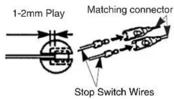
- Adjust the cable adjuster sleeve so the stop on the carburetor throttle cam just contacts the throttle stop and the cable position keep 1-2mm play between cable lug and slotted fittings when the throttle trigger is fully depressed.
- When the throttle cable is adjusted correctly, tighten the lock-nut.
- Plug the stop switch wires into the matching connectors from the engine. Note that wire polarity is not important.
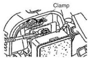
- Lap and fix the stop switch wires and connectors with clamp.
![Throttle Cable Assembly Band (2) [BF43R, BF50R]](/content/2026/05/941811/images/160b27dcfa5b407edefa58196e9d1f9f80c7cbf4fa0b4ebb8ace41b496336ae9.jpg)
[BF43R, BF50R]
Clamp the throttle cable assembly with two bands as shown.
[B43, B43R, B50R]
Lap and fix the throttle cable assembly with the pad as shown.
![Pad Throttle Cable Assy [B43, B43R, B50R]](/content/2026/05/941811/images/c5f625b9f26add5718c3a083230ce27233f7d3e9724a09319be1c534e4b155a7.jpg)
[BF43R, BF50R]
Caution! : This swivel stopper is exclusively for fixing the handle in transport. Do not engage the swivel stopper while operating the brushcutter.
In transport and strage:
Loosen the wing nut, place the stopper on A position of the bracket. Tighten the wing nut, confirm the handle is fixed by the swivel stopper.
In operation:
Before start operation of the brushcutter, disengage the swivel stopper. Loosen the wing nut, place the stopper at B position. Tighten the wing nut to fix there, confirm the handle becomes free to turn around.
![Bracket "A" Position Swivel Stopper "B" Position Wing Nut [BF43R, BF50R]](/content/2026/05/941811/images/cc8f2586ce9f4f61fad2212a07c27e6de71f833c8c10f912e247540eb9643b99.jpg)
INSTALLING DEBRIS SHIELD
DEBRIS SHIELD
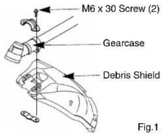
Attach the debris shield to the gearcase with the two M6 x 30 screws as shown on Fig. 1.
SHIELD EXTENSION
(Install the string cutoff blade and shield extension to the debris shield.)
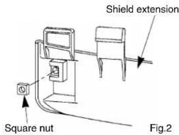
- Insert the square nut into shield extension as shown on Fig. 2.
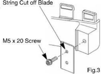
- Attach the String Cutoff Blade to shield extension using M5 x 20 Screw, locking with square nut (on Fig.2) as shown on Fig. 3.
String Cut off Blade
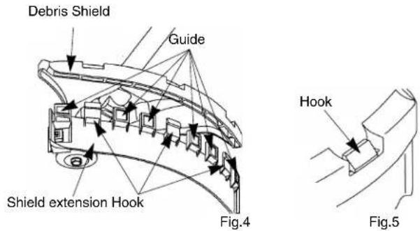
- Enter the guide in the slot of debris shield on Fig. 4. Make sure place the three hooks into the position on the shield as shown on Fig.5.
CUTTING BLADE
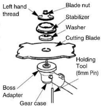
A variety of metal cutting blades are available to satisfy different cutting conditions. It is especially important to use only the correct blade(s) approved for each model brushcutter. Also, it is especially important to install the blade for LEFT- HAND rotation (as viewed from the operator's position), and to correctly position all blade holding parts (see sketch).
BEFORE OPERATION
FUEL : MIXING GASOLINE AND OIL
The two cycle engines used in the brushcutter requires a mixture of GASOLINE and OIL for lubrication of bearings and other moving parts. The proper fuel mixture ratio is 25:1, which is 40cc of oil mixed with one liter of gasoline.
NOTE : Gasoline and oil must be premixed in a clean gasoline container. Never mix gasoline and oil indoors or in the burushcutter fuel tank. Always use fresh gasoline.
WARNING !! - NEVER USE ALCOHOL OR ALCOHOL BLENDED FUELS IN MARUYAMA ENGINES.
Before filling the brushcutter fuel tank, clean around the fuel tank cap so dirt and debris does not enter the fuel tank. Always shake the fuel container before filling the fuel tank. Remove the fuel cap, then fill the fuel tank to within about 10mm from the top of the tank. Avoid filling the fuel tank filler neck. Install the cap securely onto the fuel tank.
OPERATING INSTRUCTIONS Starting and Stopping
COLD STARTING PROCEDURE
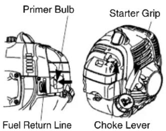
The carburetor on this engine is equipped with a fuel primer and a choke system. To start a “cold” engine properly, perform the following procedure:
- Pump the primer bulb until fuel can be seen flowing through the fuel return line to the fuel tank. (Flowing fuel should be almost clear, not foamy or full of bubbles.)
- Turn the choke lever to the Close position.
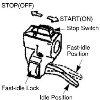
- With the stop switch "ON", and the throttle trigger positioned at Fast-idle position, pull the starter grip.
After the engine is started, turn the choke lever to the Open position. Then squeeze and release the throttle trigger to allow it to return to the idle position.
If the engine stops running before you turn the choke lever to the open position:
Go ahead and open the choke, pull the starter grip with the throttle trigger positioned at Fast-idle position.
HOT RESTART
To start the engine that is already warmed up (hot restart), or if the ambient temperature exceeds 68^(20^) :
- Pump the primer bulb until fuel can be seen flowing through the fuel return line to the fuel tank. (Flowing fuel should be almost clear, not foamy or full of bubbles.)
- Turn the choke lever to the open position, and set the stop switch to the "ON" position.
- Leave the throttle trigger in the idle position and pull the starter grip.
If the engine fails to start after you follow the above procedures, contact an authorized MARUYAMA dealer.
TO STOP THE ENGINE:
- Release the throttle trigger.
- Slide the stop switch to "STOP" position.
CARBURETOR ADJUSTMENT
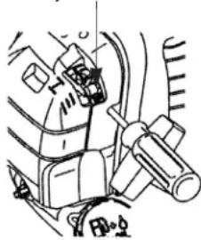
The carburetor has been carefully adjusted at the factory and should not require any further adjustment. Only the idling speed can be adjusted by turning the idle speed adjustment screw (see sketch). The correct speed is 2400 - 2800 RPM (or just below the clutch engagement speed). Turning the adjustment screw clockwise will increase the idle speed.
If further adjustment is necessary, please contact a local authorized MARUYAMA dealer.
Idle Speed Adjustment Screw
natural_image
Mechanical assembly diagram showing components like gears and shafts (no text or labels)MARUYAMA brushcutters are designed and tested to cut nearly all grasses, thick weeds and brush. As you continue to use the equipment, many tasks will become easier.
CAUTION-Read the SAFETY INSTRUCTIONS concerning the proper use of the brushcutter on page US-1.
CAUTION-Observe all warnings that appear on the brushcutter.
CAUTION-Use only the correct blade approved for the task and the machine.
CAUTION-Always use the Shoulder Harness when operating a brushcutter with a metal blade. The brushcutter must be positioned to the right side of the operator when used with a metal blade.
CAUTION-Always make certain the blade is installed to rotate in the proper direction and that all holding and fastening parts are correctly secured.
CAUTION-Remove the holding tool ( 6mm pin) before operating the equipment!
CAUTION-Do not continue to use a blade that is dull, damaged, or that vibrates during use. Whenever a cutting blade becomes clogged with debris, immediately stop the machine and clean the blade.
CAUTION-When cutting heavy brush or small trees, use the proper method to avoid dangerous "KICKBACK" (see sketch).
No Kick-back Zone
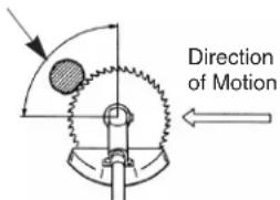
CORRECT
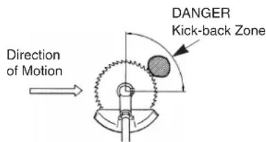
INCORRECT
REGULAR MAINTENANCE
AIR FILTER
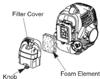
The air filter should be cleaned each time the brushcutter is used. (Or more often with extreme conditions.) Remove the filter cover and take out the element. Wash the element in kerosene or warm detergent, then squeeze it dry. Apply oil (#30 wt.) to foam, removing all excess oil. Assemble and reinstall the element and filter cover.
SPARK PLUG
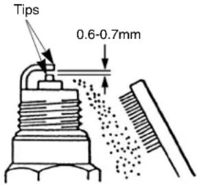
The spark plug should be removed from the engine and checked after each 25 hours of operation. The tips can be cleaned with a stiff brush. Adjust the gap to 0,6-0,7mm (see sketch). Replace the spark plug if it is oil_fouled or damaged, the average spark plug life is approximately 100 hours.
CAUTION-Do not over_tighten the spark plug. The correct torque is 10.7-16.6N·m(100 -160 kgf·cm)
COOLING FINS CLEANING
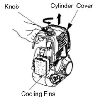
- Loosen the knob and lift off the cylinder cover.
- Clean all dirt and debris from the cooling fins and from around the cylinder base.
- Reinstall the cylinder cover.
FUEL FILTER
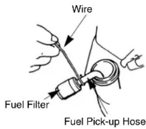
The fuel filter is attached to the end of the fuel pick_up hose inside the fuel tank. After each 25 hours of use, it should be checked for dirt or damage, and replaced if necessary. Using a wire hook, gently pull the fuel filter out through the fuel filler opening. Grasp the fuel hose next to the fuel filter fitting and remove the filter, but do not release the hose. While still holding on to fuel hose, attach the new fuel filter. Drop the new fuel filter back into the fuel tank. Make sure that the fuel filter is not stuck in a corner of the tank, and that the fuel hose is not doubled over (kinked) before refueling.
LUBRICATION : GEARCASE
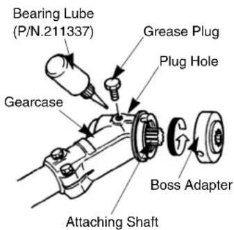
The gearcase should be checked for lubrication after each 30 hours of use. Remove the cutting attachment and the boss adapter. Clean any dirt and debris from the area between the boss adapter and the gearcase. Remove the grease plug from the side of the gearcase. While rotating the attaching shaft, Inject lithium base bearing lube (P/N 211337) through the plug hole until the gearcase is full. Reinstall the boss adapter and grease plug.
GENERAL CLEANING AND TIGHTENING
The MARUYAMA brushcutter will provide maximum performance for many, many hours if it is maintained properly. Good maintenance includes regular checking of all fasteners for correct tightness, and cleaning the entire machine.
STORAGE
For long term storage of the Brushcutter, perform all regular maintenance procedures and needed repairs. Empty the fuel tank. Start the engine and allow it to run until it stops. Pull the starter cord a few times to remove any excess fuel from the engine. Remove the spark plug and insert a small amount of oil. Pull the starter cord once and bring the piston to a position closest to the spark plug hole. Reinstall the spark plug. Store the brushcutter in a dry place away from excessive heat, sparks or open flame.
MARUYAMA®
B43, B43R, BF43R, B50R, BF50R
natural_image
Mechanical assembly diagram showing components like gears and springs (no text or labels)B43, B43R, BF43R, B50R, BF50R
natural_image
Technical line drawing of a mechanical assembly with no visible text or symbols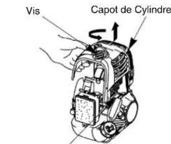
- Product Description
- ASSEMBLY INSTRUCTIONS
- ENGINE AND DRIVESHAFT ASSEMBLY
- HANDLEBAR
- CONNECTING THROTTLE CABLE AND STOP SWITCH WIRES
- [BF43R, BF50R]
- [B43, B43R, B50R]
- INSTALLING DEBRIS SHIELD
- DEBRIS SHIELD
- SHIELD EXTENSION
- CUTTING BLADE
- BEFORE OPERATION
- FUEL : MIXING GASOLINE AND OIL
- WARNING !! - NEVER USE ALCOHOL OR ALCOHOL BLENDED FUELS IN MARUYAMA ENGINES.
- OPERATING INSTRUCTIONS Starting and Stopping
- COLD STARTING PROCEDURE
- HOT RESTART
- TO STOP THE ENGINE:
- CARBURETOR ADJUSTMENT
- REGULAR MAINTENANCE
- AIR FILTER
- SPARK PLUG
- COOLING FINS CLEANING
- FUEL FILTER
- LUBRICATION : GEARCASE
- GENERAL CLEANING AND TIGHTENING
- STORAGE
- MARUYAMA®
- B43, B43R, BF43R, B50R, BF50R
Brand : Maruyama
Model : B43
Category : Lawn mower