
PDU-02I1908I-0200-C20-BK - Wall socket Lanberg - Free user manual and instructions
Find the device manual for free PDU-02I1908I-0200-C20-BK Lanberg in PDF.


| Product Type | Power Distribution Unit (PDU) for 19" rack |
| Model | PDU-02I1908I-0200-C20-BK |
| Dimensions (W x D x H) | 482.6 x 45 x 44.45 mm (19" x 1.77" x 1.75") |
| Weight | 1 kg (2.2 lbs) |
| Input Plug | IEC C20, 16 A |
| Input Voltage Range | 220 V ~ 250 V AC |
| Input Frequency | 50 Hz ~ 60 Hz |
| Output Sockets | 2x IEC C19 (16 A) + 8x IEC C13 (10 A) |
| Maximum Power | 4000 W (for 230 V/16 A) |
| Surge Protection | Yes, with green LED indicator; 3000 A ~ 5000 A |
| Power Switch | Yes, on/off toggle |
| Cable Length | 2 m (6.6 ft) |
| Cable Cross-section | 2.5 mm² (13 AWG) |
| Case Material | Anodized aluminum |
| Color | Black |
| Mounting | 19" rack, 1U horizontal; brackets included |
| Operating Temperature | -5 °C to 40 °C (23 °F to 104 °F) |
| Operating Humidity | 0% to 90% non-condensing |
| Safety Certifications | CE, RoHS, WEEE; compliant with LVD 2014/35/EU, EMC 2014/30/EU |
| Intended Use | Server rooms, data centers, CCTV systems |
| Maintenance | No user-serviceable parts; varistor replacement by qualified personnel only |
Frequently Asked Questions - PDU-02I1908I-0200-C20-BK Lanberg
User questions about PDU-02I1908I-0200-C20-BK Lanberg
0 question about this device. Answer the ones you know or ask your own.
Ask a new question about this device
Download the instructions for your Wall socket in PDF format for free! Find your manual PDU-02I1908I-0200-C20-BK - Lanberg and take your electronic device back in hand. On this page are published all the documents necessary for the use of your device. PDU-02I1908I-0200-C20-BK by Lanberg.
USER MANUAL PDU-02I1908I-0200-C20-BK Lanberg
Power distribution unit
PDU 03/04/07/08/09/10 series
Instrukcja obsługi
User's manual

PDU-04E04I-0200-BK
PDU-07E-0200-BK
PDU-07F-0200-BK
PDU-10I-0200-IEC-BK
PDU-03E-0200-IEC-BK
PDU-03F-0200-IEC-BK
PDU-04E04I-0200-IEC-BK
PDU-07E-0200-IEC-BK
PDU-07F-0200-IEC-BK
PDU-03E-0200-BK
PDU-03F-0200-BK
PDU-09E-0300-BK
PDU-09F-0300-BK
PDU-02I1906I-0200-C20-BK
PDU-02I1908I-0200-C20-BK
PDU-08I-0200-C20-BK
2.10 Model PDU-02:1908I-0200-C20-BK
PLEASE SAVE THIS MANUAL - This set of recommendations and manual instructions, for Lanberg the use of power distribution units (PDU), including the following models supported:
• PDU-03E-0200-BK, PDU-03E-0200-IEC-BK
• PDU-03F-0200-BK, PDU-03F-0200-IEC-BK
,PDU-04F04I-0200-BK,PDU-04F04I-0200-IFC-BK
contains logistics, technical instructions and regulations that must be followed during the transport, assembly, usage and maintenance of the above mentioned products. Do not use the device, before reading the manual thoroughby, and appropriately following all safety information, included within the manual keep this manual for last year. All pictures, illustrations contained in this manual are for usual purposes only. The information in this manual is provided to an open book or a book with a copy of the book, and it is also available to the same material. It is also responsible for updating, maintaining current information within this manual or to nearby its users or organizations regarding manual updates. Laiberg owners, in particular, will not be responsible for any hardware, software or data (stored or used along with) the product, including repair, replacement, integration, installation or recovery of hardware, software or data, in care of misuse of the power distribution unit ("COU") and/or its components. Laiberg owners reserve the right to introduce changes to this manual at any given line and without notice. The products exercised in this manual to obtain reliable information from their own sources. Laiberg owners are responsible for making their own products, and they may require reproduction of these products, including documentation, is prohibited, except as expressly permitted under the applicable license terms.
NOTE: For the most up-to-date version of this manual, please visit our website at www.jarlberg.edu.
1.2 Compliance with legal and regulatory requirements concerning safety and environment
This product compiles with the European Union (EU) safety and environmental regulations.
The products listed in this manual are authorized in the EU by obtaining a European Union Declaration of Conformity which complies with the essential requirements and other relevant provisions of the following directives and that the following harmonized standards apply.
The Declaration of Conformity (CE) is on the page: www.lanberg.eu
Directive: LVD 2014/35/UE.
Harmonized standard: IEC 60884-1:2002 + A1:2006 + A2:2013, IEC 60884-2-7:2013, EN 50525-2-11:2011, EN 50525-2-31:2011, EN 60320-1:2001 + A1:2007, EN 60320-2-2:1998.
Directive: EMC 2014/30/UE
Harmonized standard: EN 55014 1:2017, EN 55014 2:2015, EN 61000 3 2:2014, EN 61000 3 3:2013.

Directive: RpHS 2013/65/UE
Harmonized standard: IEC 62321-3-1:2013, IEC 62321-4:2013 + AMD1:2017 C5V, IEC 62321-5:2013, IEC 62321-6:2015, IEC 62321-7-1:2015, IEC 62321-7-2:2017.
NOTE: The use of the WEEF symbol (crossed out bin symbol) means that this product cannot be treated as household waste. Proper disposal of used equipment avoids risks to human health and the environment, resulting from the possible presence of hazardous substances, mixtures and components in the equipment, as well as, improper storage and processing of such equipment. Selective collection also allows you to recover materials and components, from which the device was manufactured. For more information about the recycling of this product, please contact the retail outlet, where the product was purchased, or request information from the local authority. The use of the RollIS symbol means, that this particular product is manufactured in accordance with the European Roll IS standard. Main goal of this norm, is to reduce the amount of hazardous substances getting into the environment, resulting from electrical and electronic waste. The use of the CE symbol means that the product is safe and compliant with EU standards and requirements.
1.3 General safety instructions and precautions
- Usage of this particular device does not require any specialized training nor electrical qualifications. The power distribution unit (PDU) performs a similar function as a regular power supply strip (domestic use only) with switch and overvoltage protection in applications such as: server rooms, data centers, surveillance or CCTV systems of small / medium / large companies etc.
- PDU is designed to operate in a controlled environment (Controlled temperature and humidity, device should work indoors, without any conductive contaminants [dust, flammable gases, corrosive substances, etc.]).
- All potential assembly, connections, wiring and circuits in which the PDU strip will be used, must be made in a manner compliant with the local electricity regulations, and in such a way, as to eliminate the risk of stepping on or tripping over them. Use only power cables with VDE and CE certification when connecting loads to the strip.
• The power socket should be easily accessible and located near the device. Be sure to connect the strip to the grounded outlet.
- Do not disassemble the case of the PDU. Inside the device there are no parts that can be repaired by the user. Refer (including replacement of vanistors' servicing to qualified maintenance personnel.
• During the warranty period it is forbidden to replace the elements of the PDU. The varistors can be replaced by qualified technical personnel.
- 19°/10° Power distribution unit (PDU) models comparison
2.1 PDU 03E 0200 BK & PDU 03E 0200 IEC BK models
| PDS-001-2001-08 Length 1 (kg) | |||||
| Input cable pin length [in (25N 6447)] | Voltage range 230V~250V | ||||
| Socets | Type:IFC-25T 3-40 | 3x Frequency range: 50 Hz ~ 40 Hz | |||
| Socete:IFCS VCE | Super protection | ||||
| IEC-211 | - | Core | Anodized aluminum | ||
| Maximum power | 400Ω [Hz] | Surge protection | Yes. Acting, turned the power LED is shunting | ||
| External drag current: 16 (A) | |||||
| Type and cable pin slot | Full times | Type and cable pin slot | Full brass B type | ||
| PDS-001-0201-0EC-BK | Color range | 2 μg | |||
| Input cable pin | IEC-214 | Scale times | 1.5 μm3 | ||
| Socets | Type:IFC-25T 3-40 | 3x | Cable construction | 3 conduction, VDE complex | |
| Socete:IFCS VCE 10/26-1 | - | Color | Black | ||
| IEC-213 | - | Operating temperature | -4V~40°C | ||
| Maximum power | 250Ω [Hz] | Outscaping humidity | 0%~90% | ||
| External drag current: 10 (A) | 0Ω [Hz] | ||||
| Type and cable pin slot | Full times | Dimensions: 2 x 5×104 | 45 x 250 x 54×50 mm | ||
2.2 PDU-03F-0200-BK & PDU-03F-0200-IEC BK Models
| PCU-097-0206-BK1ener 1 (bit) | |||||
| Input cable plug | Line scheduled (dB: 4/44/1) | Voltage range | 250V - 250V | ||
| Sectors | Fronch (NP-C513-48) | Frequency range 10 Hz - 60 Hz | |||
| Schutz (CEV/OE 10Hz) | 3x Range protection | ||||
| IEC C1 B | - | Core | Anodized at minimum | ||
| Maximum power | 400Ω (Hz) | Surge protection | Yes, Action when the green LED is shining | ||
| External plug current 16 (Hz) | |||||
| Type and cable pin slot | PL4 times | Type and cables pin slot | Full blocks it type | ||
| PCU-097-0206-IEC-BK | Cable range | 2. m | |||
| Input cable plug | IEC C14 | AWG | Cable size | 1.5 [mm2] | |
| Sectors | French (NP-C513-48) | Cable conduction | 3 conduct, VDE complift | ||
| Vdc in (dN, VCE 0726-1) | 3x | Color | None | ||
| IEC C1 B | - | Oscaming temperature | -5°C - 40°C | ||
| Maximum power | 250Ω (Hz) | Oscaming humidity | 0% - 0.5% | ||
| External plug current 16 (Hz) | |||||
| Type and cable pin slot | PL4 times | ||||
2.3 PDU-04 E04I-0200-BK & PDU-04E 04I-0200-IEC-BK Models
| TJXU 04804-0220 BEC BK | Height [μm] | |||
| Input cable plug (On-chip) (31N 40441) | Voltage range 250V~250V | |||
| Sanskets | French (HF-C210-11) | 4x Frouciry lng: 500A | ||
| Schwein (DFV-VDE M2O-1) | - | Min. nominal of the cotton | 16 A | |
| Surge protection | 3000 A ~ 3200 A | |||
| IEC C13 | 4x | Gas | Anodized aluminium | |
| Maximum power | 4000 (kΩ) | Surge protection | Yes, Active, when the green LED is driving | |
| Internal plug current 16 kΩ | Type and mode's pin and | Full frame at port lumber (ECI) | ||
| Type and mode pin slot | Full frame | |||
| TEU 04804-0220 BEC BK | Cube length | 2 m | ||
| Input cable plug | IEC C14 | Cable cross | 1.5 mm | |
| Sanskets | French (HF-C210-11) | 4x | Cable horizontal | 3 condu imp, VDE complete |
| Schwein (DFV-VDE M2O-1) | - | Color | Black | |
| IEC C13 | 4x | Operating temperature | -3°C ~ 60°C | |
| Maximum power | 2500 (W) | Overcuting humidity | 0% ~ 90% | |
| Internal plug current 16 kΩ | Angle | 1 (cm) | ||
| Type and mode pin slot | Full frame | Dimensions: 3 x 40 x 5 x 6 | 45 x 400 x 44.49 mm | |
2.4 PDU-09E-0300-BK model
| RDC 01E 000' BK Knight | 1/2 | ||||||
| Input cable pin (Lock/brain) [71N (444)] | Voltage range 230V~250V | ||||||
| Sousels | Ducts (0F-2.5T-314) | Hz | Frequency range 50 Hz ~60 Hz | ||||
| Schrook (DR/008 W2-1) | Max current of switch 16 (%) | ||||||
| EC-211 | |||||||
| Maximum power (900V-3W) | Case Annotated aluminum | ||||||
| External plasurums in 16 (A) | Type and cable pin port | Full times (B type) | Cable construction | Junctional, VDI component | Onboard protection | ||
| Type and cable pin port | Full times | Cable length | 3 (m) | Operating temperature | 3°C~40°C Weight | 1.0 Kg | |
| Case Block Connection: 1.5 mm | 1 | Operating humidity | 50~40% | Dimensional x 50x 40 | |||
2.5 PDU-09F-0300-BK
| PDC 097-200.8K (kg) | ||||||||
| Input cable pin: Uni-schubu (20140441) | Voltage range 220V~25V | |||||||
| Sanskets | French MFC 31-31# | - | Frequency range 50 Hz ~ 60 Hz | |||||
| Schulze (20140442) (Hz) | Hz | Mass current of the switch 16 [Hz] | ||||||
| ECC 11 | ||||||||
| Maximum power (0101.0W) | Cap Area and Minimum | |||||||
| Internal plug current (kA) | Type and socket's pin set | Full swing (Hz) | Circle correction | I conductors, X1 correct | Overload protection | Yes | ||
| Type and socket pin set | Full swing | Cable length | 3 μm | Operating balance size | -5 °C ~ 40 °C, Weight | 1.0 μg | ||
| Core Black Cable output 15 mm | η | Operating balance | 0% ~ 90% | Dimensions (x X x H) | 45 x 4826 x 4445 mm | |||
2.6 PDU-04F04I-0200-BK & PDU-04F04I-0200-IEC-BK models
[7^8]  | Height 1 (mm) | ||||
| Input cable plug (Unit cable pin 10 N 4044 H Voltage range 2.0 | |||||
| Semi-wks | French and C-31-31 # | 7# | Frequency range 50 Hz - 60 Hz | ||
| Schweid (29K 0X) (16x1-x) | - | Max comment of the other 15 A | |||
| IEC C13: Super protection 1000 A - 5000 A | |||||
| Maximum power: 4000 Ω | Case Anodized minimum | ||||
| External plug current: 16 A | |||||
| Type and cable pin count | Full base | Large protection | Yes Active, when the current LED lighting | ||
| TOU 0400A: 0200 IEC 8K | Type and cable pin count | Full base / ETC | |||
| Input cable plug | IEC C14 |  | Cable length | 2 mm | |
| Semi-wks | French and C-31-31 # | 7# | Cable width | 1.3 [mm] | |
| Schweid (29K 0X) (16x1-x) | - | Lands construction | 1 construction, VDI compared | ||
| IEC C13: | - | Block | |||
| Maximum power: 2500 Ω | Color using temperature scinding humidity | 5°C - 40°C | |||
| External plug current: 10 A | 0.0 - 90 °C | ||||
| Type and cable pin count | Full base | Weight | 1 Kg | ||
| Dimensions L×W×Φ | 45 x 482.6 x 44.45 mm | ||||
2.7 PDJ 07F 0200 BK & PDU 07F 0200 IEC BK models
| PDU-07F-0027-BK Height*10 | |||||
| Input cable plug (Inchette, 32N 194HT), Voltage range (250V~250V) | |||||
| Scechis | Length (80" C 250" H) | Frequency range (Hz) |  | ||
| Schning (3PN VDE WQ25 T) | 7kW, turn- of the switch in (K) | ||||
| IEC-C 3. Super protection 1000A ~ 3500 | |||||
| Maximum power (900mA) | Core Advanced Level form | ||||
| Internal plug current: 16 [A] | |||||
| Type and cable pin sort | Full base | Stage protection | Yes, acting, when the green LED driving | ||
| PDU-07F-0027-IEC-BK | Type and socket pin sort | Full base of type | |||
| Input cable pin | IEC-E4 |  Color Length 2 pm
 | |||
| Scechis | Length (80" C 251.51.46) | - | Cable cross 1.5 [mm2] | ||
| Schning (3PN VDE WQ25 T) | 7a | Cable construction 3 conductors VDE compliant | |||
| IEC-C 3. + | Block | ||||
| Maximum power (900mA) | Operating temperature -5°C ~ 4°C | ||||
| External drag current: 10 [A] | Operating humidity 0% ~ 90% | ||||
| Type and cable pin sort | Full base | Weight 10kg | |||
| Dimension of weight in 6x 100A or 14.5 mm | |||||
2.8 PDJ-101-0200-EC-BK model
| INR-C14-2004-E16-38 | Height 1.0 | ||||||
| Innir cable plug | EC C14 | Voltage range | 220V~250V | ||||
| Schematic | Fragcable HD-C14-TB | - | Frequency range | 50Hz~50Hz | |||
| Schlumber (CHN) (KJ) | - | Allow current of the switch TA [A] | |||||
| EC C14 | 1Pa | Supply protection | 3200V~5000V | ||||
| Maximum power 2570.7kV | Cate/Analyzed capacity | ||||||
| External plug current 10.0kV | Type and current's pH test | Full current 200s | Cable convection | I conduction MIL complaint | Range protection | ||
| Type and cable plug volt | Full time | Cable length | 2mJ | Operating for electrical | -5°C~40°C, Weight | 1 Bag | |
| Color: Black Cable rating | 1.5 mm3 | Operating up -5kHz | 50~100% | Dimensions in L*2.5 inch | |||
29 PDU-0219061 0200 C20 BK model
| FDU-021506-0220-C20-BK | Height 1/10 | |||||||
| Invert cable plug: | EC C20 | Voltage range | 220V ~ 250V | |||||
| Sockets | Length(NF C20 314) | Frequency range | 50Hz ~ 50Hz | |||||
| EC C19 | 2x | Max. current of the switch 16 (°C) | ||||||
| EC C18 | 6x | Single connection | 100Hz ~ 500Hz | |||||
| Maximum power 00200 (W) | Core Adjusted minimum | |||||||
| External push button, 16 (K) | Type zinc socket's pill slot | Full blocks | Calc conduction | Conductors W/O conlature | Single contactors | Yes. Adjust on the green laser to firing | ||
| Type zinc slot port | Full blocks | Cable length | 2 (m) | Operating in type white | +TC ~ +DC Weight | 1 kg | ||
| Color Black Capacitors | 2.5 [mm2] | Damping humidity | 5%~50% | Dimensions for 1.5 x 0.5 | 45 x 402.6 x 44.45 [mm2] | |||
2.10 PDU-021190III-0200-C20-BK model
| FEMA-013 088-092-04-2014 | Length [μm] | |||||||
| Input cable plug | IEC Q25 | Voltage range | 220V ~ 230V | |||||
| Schematic | Frequency (MHz) | - | Frequency range | 50Hz ~ 50Hz | ||||
| IEC Q16 | 2x | Max. current of the switch [Ω] | ||||||
| IEC Q18 | 8x | Surge protection | ||||||
| Maximum power (0000 V) | Core Analyzed dimensions | |||||||
| Internal plug current [kA] | Type and worker's pin size | Unit length | Cable convection | I conductors W/L component | Surge protection | Max. | ||
| Type and cable port work | Full times | Cable length | 2 μm | Operating voltage reading | 5°C ~ 40°C Weight | 1 [kg] | ||
| Color Black Cable group | 25 [mm3] | Operating bus TFPB | 50%~50% | Dimensions of L×20 x·h | 45 x 482.6 x 44.45 mm3 | |||
2.11 PDU-08I-0200-C20-BK model
| PDU-08I-0200-C20-BK Height 1 [U] | ||||||||
| Input cable plug IEC C20 V | Voltage range 220V ~ 250V |  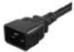 | ||||||
| Sockets | French(NF C 61-314) | -Frequency range | ||||||
| Schuko (DIN VDE 0620-1) | - | Max. current of the switch | 16 [A] | |||||
| IEC C13 | 8x | Surge protection | 3000A ~ 5000A | |||||
| Maximum power 4000 [W] | Case Anodized aluminum | |||||||
| External plug current | 16 [A] | Type and socket's pin sort | Full; brass | Cable construction | 3 conductors, VDE compliant | Surge protection | Yes. Active, when the green LED is shining | |
| Type and cable pin sort | Full; brass | Cable length | 2 [m] | Operating temperature | -5°C ~ 40°C Weight | 1 [kg] | ||
| Color Black | Cable cross | 2.5 [mm2] | Operating humidity | 0% ~ 90% | Dimensions (L x W x H) | 45 x 482.6 x 44.45 [mm] | ||
2.12 Meaning of elements, located on the power distribution unit (PDU)
-
VDE cable with IEC C14 plug (models with the IEC indication in the product name) or with French plug, at the end of cable,
-
French plug of the input cable,
-
IEC C14 plug of the input cable (only models with IEC indication in the name),
-
Mounting brackets intended for fixing the strip in the ICT server rack / 19" / 10" rack,
-
Power switch. If the side of the switch with the white circle icon is tilted upwards, it means that the strip is turned off. If this half is tilted the opposite way, it means that the strip is turned on.
-
Surge protection LED. If the LED is green, the protection is active.
-
Schuko socket,
-
French socket / 230V PL,
-
IEC C13 Socket.
-
IEC C19 socket,
-
IEC C20 plug of the input cable (only models with C20 indication in the name).
-
The electric path is follows: L (phase wire) – red, N (neutral wire) – blue, G (ground wire) – yellow.

3. Assembly within ICT rack / 19" / 10" rack cabinets
-
Select 1 unused 1U slot on the vertical mounting rails of the ICT rack / 19" / 10" rack and align those holes with the holes found on the power distribution unit (PDU).
-
Insert up to 4 metal baskets, bent at the end, with mounting basis inside them, into up to 4 designated holes (mentioned in point (1)), in such way, so the bent ends of metal baskets will slide, click into and grab the designated holes on the vertical mounting rails, from the outside.
-
Enter up to 4 screw washers and then insert and screw up to 4 M6 screws from the outside through the selected holes (point (1)) of the vertical mounting rails.
4. Connecting and disconnecting the PDU and connecting and disconnecting the devices to or from the PDU
-
To connect the power strips to the mains or the UPS, insert the plug of the input cable of the switched off power strip into the appropriate socket of the power source, which will correspond fully to the specification of the PDU's plug. Then turn on the strip by switching the switch to the "ON" position – only PDU for 19" racks. In the case of PDU 03 series (intended only for assembling in 10" cabinets) connecting the plug of PDU to the source power socket will cause the current will appear on PDU output sockets.
-
To disconnect the power strip, turn it off first, and then remove the plug of the input cable from the source power outlet – only PDU for 19" racks. In the case of PDU 03 series (intended only for assembling in 10" cabinets) turn off the connected devices and pull out their plugs from the outlet sockets of PDU, and then pull out the PDU plug from the source power socket.
-
To connect an external device to the terminal, insert the plug of this device in its appropriate socket, which will correspond fully to the specification of the plug of the output socket of the strip.
-
To disconnect the external device from the PDU, remove the plug from its socket by switching off, beforehand, the external device (if it is possible).
E-mail: support@lanberg.pl | support@lanberg.eu
www.lanberg.pl | www.lanberg.eu


- POWER DISTRIBUTION UNIT
- PDU 03/04/07/08/09/10 SERIES
- INSTRUKCJA OBSŁUGI
- USER'S MANUAL
- 2.11 PDU-08I-0200-C20-BK MODEL
- 2.12 MEANING OF ELEMENTS, LOCATED ON THE POWER DISTRIBUTION UNIT (PDU)
- ASSEMBLY WITHIN ICT RACK / 19" / 10" RACK CABINETS
- CONNECTING AND DISCONNECTING THE PDU AND CONNECTING AND DISCONNECTING THE DEVICES TO OR FROM THE PDU
Brand : Lanberg
Model : PDU-02I1908I-0200-C20-BK
Category : Wall socket