
CM2000 - Weather Station ClimeMET - Free user manual and instructions
Find the device manual for free CM2000 ClimeMET in PDF.


| Product Type | Professional Weather Station |
| Brand | ClimeMET |
| Model | CM2000 |
| Display Console | Touch-screen with backlight; indoor temperature, humidity, barometric pressure, time/date; outdoor temperature, humidity, wind speed/direction, rainfall, weather tendency; data logging for 4080 sets |
| Outdoor Sensor Suite | Thermo-Hygro Transmitter, Rain Gauge, Wind Cups (speed), Wind Vane (direction); wireless transmission to console |
| Wireless Range | Up to 100 meters (330 feet) in open field |
| Radio Frequency | 433 MHz / 868 MHz / 915 MHz (North America) |
| Time Synchronization | DCF-77 radio-controlled clock (Germany) |
| Outdoor Temperature Range | -40°C to 65°C (-40°F to 149°F); accuracy ±1°C; resolution 0.1°C |
| Indoor Temperature Range | 0°C to 50°C (32°F to 122°F); resolution 0.1°C |
| Humidity Range (Outdoor/Indoor) | 10% to 99%; accuracy ±5% |
| Wind Speed Range | 0 to 160 km/h (0 to 100 mph); accuracy ±1 m/s (speed <10 m/s) or ±10% (speed >10 m/s); units: km/h, mph, m/s, knots, Beaufort |
| Wind Direction | Visual compass; user-adjustable alarm |
| Rainfall Range | 0 to 9999 mm; accuracy ±10%; resolution 0.3 mm (<1000 mm) or 1 mm (>1000 mm); units: mm or inch |
| Barometric Pressure Range | 300 to 1100 hPa (8.85 to 32.5 inHg); accuracy ±3 hPa (700-1100 hPa); units: hPa, inHg, mmHg |
| Weather Tendency | Visual forecast based on pressure changes; user-adjustable threshold |
| Data Logging | 4080 complete data sets with time/date; adjustable interval (5-240 min via PC software) |
| PC Connectivity | USB cable; EasyWeather software for Windows (NT4, 2000, XP, Vista, 7, 8); data display, graph, export to Excel, upload to wunderground.com |
| Power Supply | Display Console: 2 x AA 1.5V batteries; Outdoor Sensor: 2 x AA 1.5V batteries; optional AC adapter for console |
| Battery Life | Console: min. 12 months; Outdoor sensor: min. 24 months (use suitable batteries for low temperatures) |
| Maintenance | Occasional cleaning of sensors; replace batteries when low; ensure rain gauge free of debris |
| Box Contents | Display console, thermo-hygro transmitter, rain gauge, wind cups, wind vane, EasyWeather CD, USB cable, mounting poles (2), sensor shelves (3), jubilee clips (2), cable ties (4), installation screws |
Frequently Asked Questions - CM2000 ClimeMET
User questions about CM2000 ClimeMET
0 question about this device. Answer the ones you know or ask your own.
Ask a new question about this device
Download the instructions for your Weather Station in PDF format for free! Find your manual CM2000 - ClimeMET and take your electronic device back in hand. On this page are published all the documents necessary for the use of your device. CM2000 by ClimeMET.
USER MANUAL CM2000 ClimeMET
Professional Weather Station
CM2000
Instruction Handbook
ClimeMET
Welcome to the ClimeMET CM2000 Weather Station.
The CM2000 Professional Weather Station from ClimeMET is a new way to monitor the weather in your surroundings. Utilizing a touch-screen display console, the user-friendly interface means the measurement and logging of comprehensive weather data has never been easier.
The outdoor sensor suite is able to measure temperature, humidity, rainfall, wind speed & direction and more, which are then transmitted wirelessly to the display console and displayed alongside internal readings such as temperature and barometric pressure. Beyond the display console, the CM2000 also allows you to download your weather data onto a computer using the supplied EasyWeather software in order to create your own archives.
Begin by familiarising yourself with the features of the CM2000 Weather Station and plan your installation accordingly. Ensure that the outdoor sensor suite is assembled correctly before installing it in its permanent location – especially if this is not somewhere you can later access with ease. Now place the display console in a suitable location and you're set!
Please see the Sensor Suite and Console Overview sections for further information and advice on the installation of your new weather station. Make sure to read through this manual in order to get the most out of the CM2000 and you'll soon have years of weather data at your fingertips.
Thank you for choosing ClimeMET.
This manual should be kept in a safe place for future reference as it contains important notes on the setup and operation of your weather station.
This handbook may contain mistakes and printing errors. The information in this handbook is regularly checked and corrections made in the next issue. We accept no liability for technical mistakes or printing errors, or their consequences. All trademarks and patents are acknowledged.
Contents
What's in the Box? Page 3
Base Station Features ...... Page 4 & 5
Sensor Suite ...... Page 6
Sensor Assembly...... Page 6 - 10
Getting Set Up...... Page 11 & 12
Choosing your Location...... Page 12 & 13
The Display Console Page 14 - 26
EasyWeather PC Connection ...... Page 27
EasyWeather PC Software Connection...... Page 27 - 37
Maintenance & Troubleshooting...... Pages 38 & 39
Weather Station Specifications 40 & 41
What's in the Box?
Display Console
Thermo-Hygro Transmitter
Rain Gauge
Wind Cups
Wind Vane
EasyWeather Installation CD
USB Cable
2 x Mounting Poles
3 x Sensor Shelf
2 x Jubilee Clip
4 x Cable Tie
Installation Screws
You May Also Need:
Philips screwdriver
A compass to orient the Sensor Suite
Additional installation parts – please see the ClimeMET Installation Kit if required

Please help in the preservation of the environment and return used batteries to an authorized depot.
All rights reserved. This handbook must not be reproduced in any form, even in excerpts, or duplicated or processed using electronic, mechanical or chemical procedures without written permission of the publisher.
Base Station Features
The ClimeMET CM2000 Display Console uses touch-screen technology to help with navigation of the various sub-menus and settings available. Viewing min/max records or setting alerts for a weather measurement is therefore typically a case of pressing the relevant section of the console, then using the sub-menu for that specific parameter. A stylus is included to assist with use of the touch screen – you can find this on the top left corner when looking at the rear of the console.
Base Station Features Continued
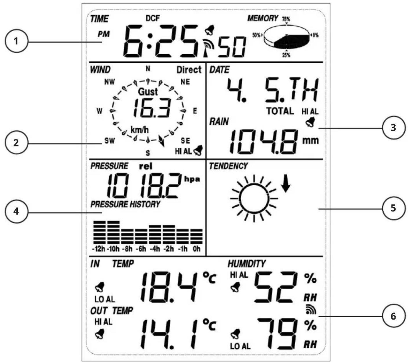
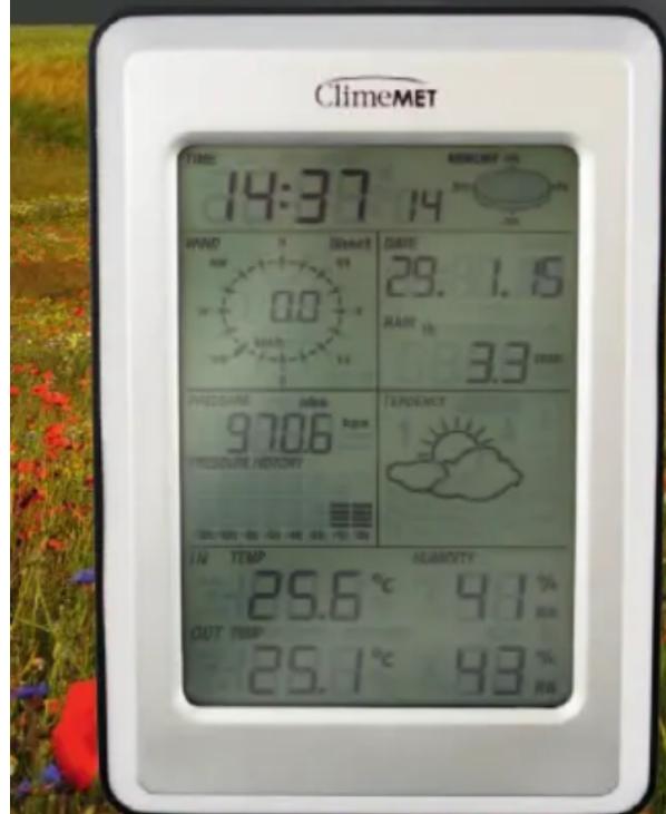
The top line section of the display console includes time and date information. You can set this manually if you wish, but the CM2000 will periodically synchronize with the DCF-77 Radio Signal in order to ensure accuracy. On the right hand side of this section, you can also see a pie-chart displaying the memory usage and remaining space available on the internal datalogger.
2 The upper-left box is used to display wind readings. Wind direction is visually represented with a compass showing an indication arrow, while the wind speed is displayed as a numeric value within this compass with the selected unit of measurement shown below.
3 The upper-right section shows the date in the chosen format (default DD/MM/YY) along with rainfall readings in your selected unit of measurement.
4 The lower-left portion of the screen is used to display barometric pressure. This is shown in a numeric value, alone with a visual pressure-history graph covering the most-recent 12 hours.
The lower-right section presents weather tendency – a visual forecast of the weather based upon the recent changes in barometric pressure.
⑥ Finally, the bottom box will display indoor and outdoor readings for temperature and humidity. Temperature is shown on the left, with humidity on the right.
Please Note: All functions of the weather station are accessed by using the touch screen to press on the relevant area. Touching a section will enter a sub-menu where changes can be made, often by then using the + or - buttons that will now display. Each time a segment of the screen is pressed, a sound will be made and the backlight will illuminate. If nothing is pressed for 30 seconds, the display will revert back to the normal display mode.
The Sensor Suite
The ClimeMET CM2000 uses multiple sensors to measure various weather parameters. These are comprised of the Rain Gauge, Wind Cups (to measure speed), Wind Vane (to measure direction) which then connect into a Thermo-Hygro Transmitter. This transmitter measures external Temperature and Humidity, but is also responsible for wirelessly sending all of the outdoor readings back to the Display Console.
Sensor Assembly
flowchart
graph TD
    A["Top Left"] --> B["Central Component"]
    B --> C["Bottom Right"]
    style A fill:#f9f,stroke:#333
    style C fill:#bbf,stroke:#333
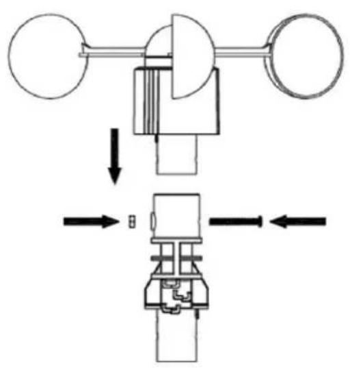
Firstly, push the set of wind cups onto either side of the mounting shelf. Line this up carefully – on one side of the mounting shelf will be a hole with a hexagonal shape around the outside. Line this hole up with the hole at the bottom of the wind cups. Please note – these cups will only fit onto the shaft one way round, so if it doesn't seem as though it fits properly, please try lining it up the other way! With the holes lined up correctly, insert a long screw through one side and tighten the nut onto the other end to keep the sensor in place.
Next, mount the directional wind vane onto the other side of the mounting arm in the same manner. Once this is lined up properly, insert another long screw through the hole and tighten the nut onto the other end.

natural_image
Technical diagram of a mechanical device with directional arrows indicating movement or force (no text or symbols present)Sensor Assembly Continued

natural_image
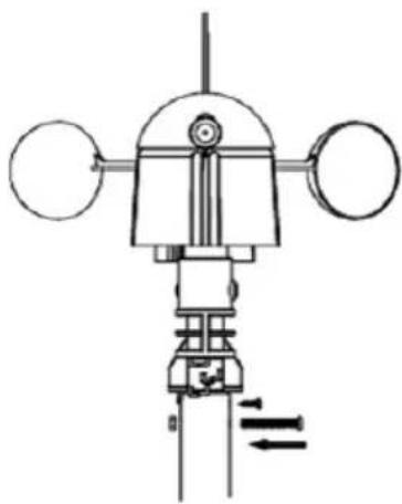
Technical diagram of a mechanical or electrical device with no visible text, numbers, or symbols.Inspect your two steel mounting poles and you'll find that one of these has a small hole towards one end. Firmly push your assembled mounting shelf into the end of this mounting pole so that the holes line up and the shelf is sitting straight.
Then insert another long screw through these holes and tighten as before using another nut, as shown below.
natural_image
Technical line drawing of a mechanical device with no visible text or symbols
natural_image
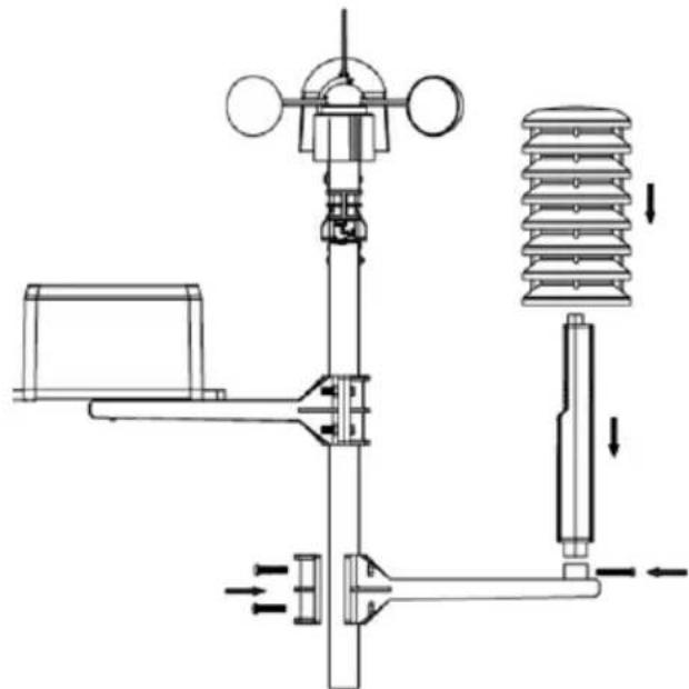
Technical line drawing of a mechanical or electrical device with no visible text, numbers, or symbols.Next, mount the rain gauge. It's best to attach the side mounting shelf onto the installation pole first – begin by loosening the four large screws on the shelf attachment so that you are able to open this wide enough to fit the installation pole through. Ensure the shelf is turned the right way (square attachment facing upwards) and slide the shelf around halfway up the pole, then re-tighten the attachment so that it doesn't slip.
Sensor Assembly Continued
With the shelf securely attached, firmly push the rain gauge down onto the square attachment and use one of the small screws to secure this via the hole found at the underside of the mounting shelf.
natural_image
Technical line drawing of a mechanical assembly with no visible text or symbolsAdd the remaining installation pole by pushing it firmly into the open-end of the existing one using the swaged end - this will give you more height and room to install the final sensor.
Now follow a similar procedure to before in order to add the final mounting shelf and install the thermo-hygro transmitter. However – this time, the sensor will be secured using a long screw that needs to be inserted horizontally in the hole found directly below the battery compartment.
natural_image
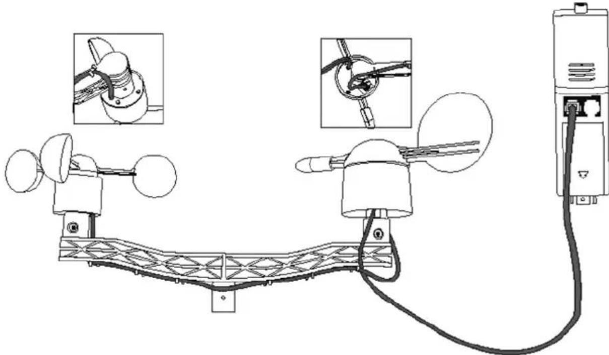
Technical line drawing of a sensor or measurement device connected to a power outlet, with inset diagrams showing close-ups of components (no text or symbols present)Begin connecting the external sensors using the cables provided. Firstly, connect the wind cups to the wind vane – the connection port is found on the underside of the wind vane. Then, connect the cable running from the wind vane into the port on the thermo-hygro transmitter labelled 'Wind'. Please ensure that this clicks into place fully, as if it is not properly inserted you won't receive any readings from either wind sensor.
Sensor Assembly Continued
The Rain Gauge connects directly into the Thermo-Hygro Transmitter, into the remaining connection port labelled 'Rain'. Again, please ensure this is fully inserted now, as the sensor suite is likely to be difficult to access later.

natural_image
Technical line drawing of a weather monitoring system with sensors and a sensor mounted on a bridge (no text or labels)At this point, it's a good idea to power up the CM2000 and check that all of your outdoor readings are being successfully received. It's likely that the external sensors will be difficult to access later once set up, so it's well-worth checking that everything is operating properly now.
First, insert the 2 x AA Batteries into the Thermo-Hygro Transmitter to begin the transmission of data from the outdoor sensors. Quickly afterward, power the Display Console either using batteries or optional power adapter, then leave the console until the outdoor data begins being displayed. When the Display Console turns on, it begins looking for a signal from a Transmitter within range. If you therefore have a Transmitter already sending data, this should mean that it is picked up by the Display Console quickly.
Once everything is synchronised correctly, you can proceed with installing the weather station in its permanent location.
Sensor Assembly Continued
Ensure all sensors are installed correctly and mounted firmly onto the installation poles. You can now use the two Jubilee Clips supplied in order to mount the lower installation pole to an existing mast or surface that will be suitable.

Attach these clips so that they contain the installation pole of the CM2000 and the desired attachment. Tighten each of these securely using a flat-head screwdriver to ensure the station does not sway and is vertically level.
Before tightening this fully – ensure that the directional vane is facing the correct orientation. If the vane is pointing directly away from the station (in line with the mounting shelf) then it will be measuring East, whereas if the pointer is pointing exactly towards the wind cups it should be facing West. It's worth using a compass to check the orientation of the station matches this completely, as otherwise the wind direction readings will be incorrect. Try to rotate the CM2000 pole so that wind direction sensor on the top shelf is on the East side before tightening all poles fully.
Getting Set Up
After all sensors have been assembled and plugged in to correct ports on the Thermo-Hygro Transmitter, you can power the station and begin receiving information from the sensor suite.
Thermo-Hygro Transmitter:
Insert 2 x AA batteries into the compartment on the front of the unit. The red indicator on the transmitter should illuminate for 4 seconds, before turning off and then flashing intermittently from then onwards.
Display Console:
- Open the battery compartment at the back of the display console and insert 2 x AA batteries, then replace the battery cover.
- When the batteries are first inserted, all icons and symbols will briefly be displayed. The console will then enter normal mode and begin searching for the outdoor transmitter. Please don't touch the screen until the outdoor information is received, as this will interrupt the searching process.
- Within 10 minutes, the outdoor information should be shown on your display console. The best way to check this is to look for an outdoor temperature reading, which should be found in the bottom-left hand corner of the screen. Once the outdoor data is being received, you can use the console as you wish.
- The Console will also now search for the DCF-77 Radio Signal in the background. The CM2000 synchronises to this time signal in order to ensure that time and date information remains as accurate as possible. Initially, the station will try to find this signal once every hour until it is successful – once the signal has been found the Radio Tower icon will be shown on the Display Console. This process can sometimes take several hours to complete, as atmospheric interference can prevent the time signal from being received easily in some areas.
Please Note: Once the radio signal has been received, it will overwrite any date/time settings that have been set manually. It may therefore seem as though the console has 'jumped' forwards or backwards a few minutes if these times do not match exactly, but it will simply be displaying the DCF-77 Time.
Getting Set Up Continued
Setting up with an Adaptor:
If you are using an adaptor with this station, follow the same process detailed above for the Display Console, but begin by plugging in the adaptor instead of inserting batteries into the compartment at the back of the console. The rest of the setup process will now be the same.
Choosing Your Location
Once you have checked that all components of the station are set up and working properly, they can be installed in their permanent places. It's worth checking that the transmission can still be received by the console at the desired location, as any connection problems can typically be resolved by a slight change of location. The maximum communication distance between Console & Transmitter is 330 Feet providing there are no interfering obstacles such as buildings, vehicles or trees. Please place the Console & Transmitter at their desired locations and check the connection is consistent before setting these up permanently.
The sensors of the ClimeMET CM2000 each have their own cables attached to them. While they must all physically connect to the Thermo-Hygro Transmitter, this cable allows for a flexible installation as you are able to separate the sensors in order to achieve the most accurate measurements possible.
Traditionally, different weather parameters are measured at different heights as this can have a significant effect on readings. For example - placing your wind sensors up high should ensure you receive the best wind readings possible, though an elevated height is also likely to lead to reduced rainfall readings, as the stronger winds will have an impact.
When planning your installation, you might want to therefore consider the following:
- Air Temperature is typically measured at 1 to 1.5 Metres above ground level. The shield covering the temperature sensor ensures that the sensor itself is shaded and ventilated, which will maintain the accuracy of the temperature readings.
Cont.
Choosing Your Location Continued
- A general rule for achieving the best accuracy is keeping the station at twice the distance of any nearby object's height, so for example 20ft away from a 10ft tree.
- Rainfall is normally measured at around 30cm above ground level. At elevated heights higher-wind speeds will have an effect on the catchment of rainfall, so readings may be reduced. It's also worth noting that the rain gauge may need to be cleared if any leaves or debris create a blockage, so it's worth considering the accessibility of the station beforehand.
- The optimum height for wind speed measurements is around 10 metres above ground. This will typically not be possible for residential installations, so it's often advised to mount alongside a chimney or existing mast if available. If doing so, it's important to try to have a clearance of at least a metre in height between the weather station and roof line.
The Display Console
The Display Console Continued
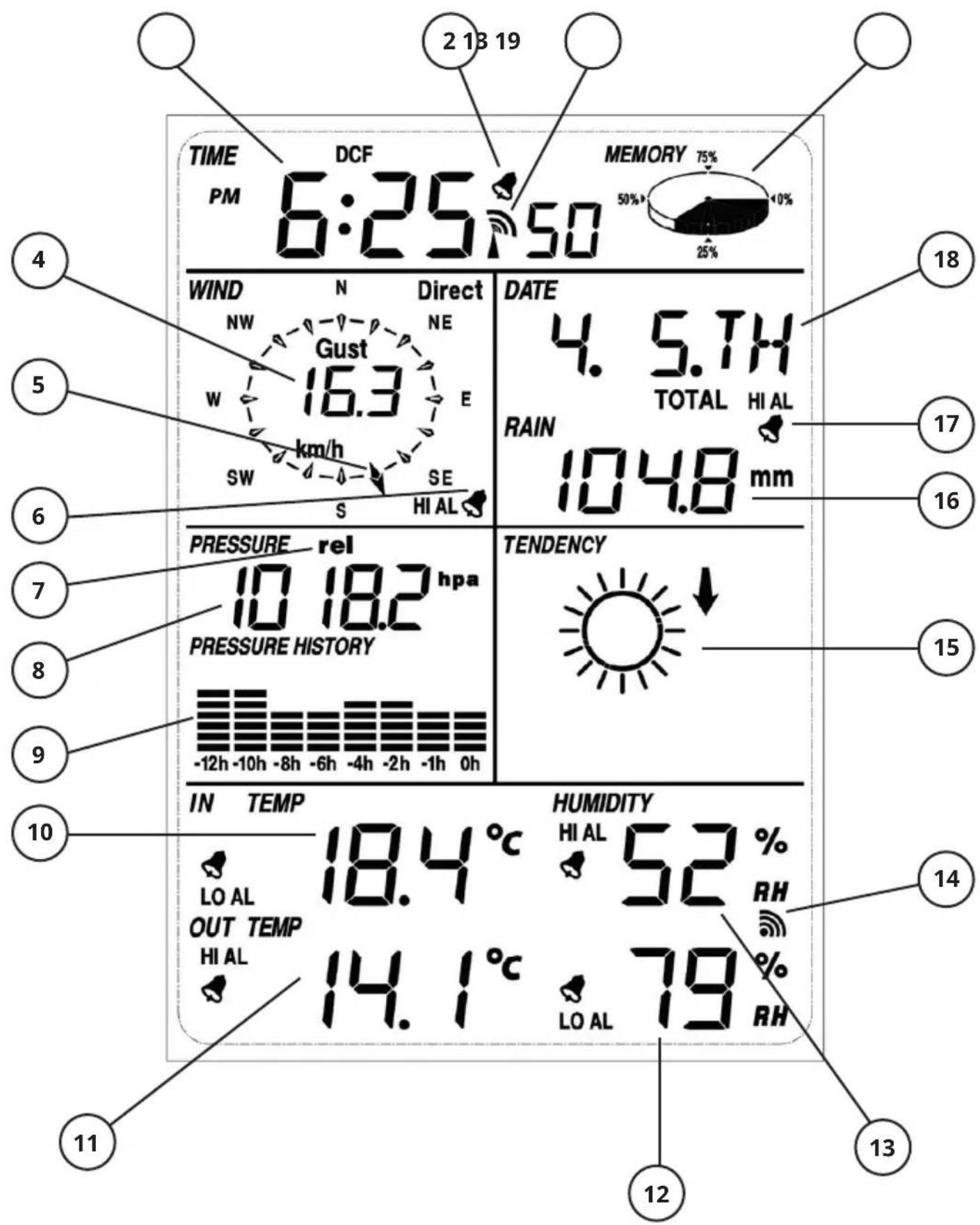
- Radio Controlled Clock signal – indicates the console is looking to synchronise to DCF-77 time signal
- Alarm icon - shown if a timed alarm has been set
- Current Time – Time shown in 12/24 Hour format as selected
- Wind Speed – Shown in selected units
- Wind Direction – Visual representation of directional wind conditions
- Wind Alarm icon – displayed if a wind speed alarm is set
- Pressure Format - confirms if barometric pressure displayed is relative or absolute
- Barometric Pressure - Value shown in selected units
- Pressure History – Visual representation of changes in pressure over recent 12-hour period
- Indoor Temperature – Measured by Display Console and shown in selected units, with separate alarm icon if set
- Outdoor Temperature – Measured by Thermo-Hygro Transmitter and shown in selected units, with separate alarm icon if set
- Outdoor Humidity - Measured by Thermo-Hygro Transmitter and shown in selected units, with separate alarm icon if set
- Indoor Humidity - Measured by Display Console and shown in selected units, with separate alarm icon if set
- Reception Signal – Shown when Display Console receives data from Transmitter
- Tendency – Visual forecast of upcoming weather, based upon recent changes in barometric pressure
- Rainfall – Amount of rain measured, shown in selected units
- Rainfall Alarm icon - shown if an alarm has been set to indicate rain
- Date - Shown in selected Day, Month & Year format
- Memory – Visual indication of used & available memory of Display Console
Console Features
To navigate through the various features available on the CM2000 Display Console, you will need to touch the screen in the desired area. Pressing each of these segments will open up a sub-menu that will then allow you to set and change various conditions. For certain settings you will need to press on a specific segment multiple times – the below guide will explain what you will see in each section after a certain number of key presses.
Please note: you can exit any of these sub-menus at any time by touching another area of the screen that isn't flashing or displaying +, - or ON/OFF.
Time:
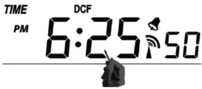
- Touch the Time section once and it will read 'LDC5'. The + and - symbols will also begin flashing in the lower right segment. This setting allows you to adjust the contrast level of the screen – use the + and - symbols to adjust the figure next to 'LCD' between 0 and 8. Setting this value higher will make the screen easier to read, but will also slightly affect battery life.
- Touch the Time section again while this menu is still flashing (or simply press it twice from the home screen) to enter the Time Zone setting. Use the + and - buttons shown again in the lower-right segment to adjust this value up or down.
Please note: This station receives the DCF-77 radio signal broadcast from near Frankfurt, Germany. Therefore, when it receives the synchronised time, it will be set to GMT+1 as default, which will match Time Zone 0 on this weather station. Therefore, if you are looking to use it within the UK, you'll need to change this Time Zone setting to -1 to compensate for the difference in European time, while still remaining synchronised to this radio signal.
Console Features Continued
- Touching the Time section for a third time will allow you to choose between 12 or 24 Hour time display. Simply use either of the + or - symbols to toggle between the settings.
The final settings in the Time menu are for manually setting the time of the console. However – please note that once the time signal has been picked up by the console it will overwrite any manual settings, so you may not wish to set these.
- Pressing the Time section four times will display the current time with the Hours section flashing. Use the + or - symbols to increase/decrease this figure as desired.
- Pressing the Time section again will move the selection over to the Minutes section. Again, use the + or - symbols to change this value as required.
Memory:

pie
MEMORY | Category | Percentage (%) | | :--- | :--- | | Segment 1 | 75 | | Segment 2 | 50 | | Segment 3 | 25 | | Segment 4 | 0 |- Touch the Memory section to activate the historic data, the + and - button will also be flashing in the lower-right section. Press the - key to toggle through earlier records complete with the Time stamp that these measurements were made (30-minute intervals by default, but this can be changed using the software) or alternatively use the + key to view more recent sets of data.
- Touching the Memory section again will open the Memory clearing procedure. The Memory pie chart will now flash with the word 'CLEAR' displayed underneath. Pressing and holding the Memory pie chart full 3 seconds will now fully clear the data stored on the Display Console. This option cannot be revered, so please only use it if you have uploaded your weather data to the EasyWeather software and are certain you want to clear the console of data!
Console Features Continued
Wind:

-
Touch the wind section once and the wind speed will begin flashing. To the right will also be the flashing + and - symbols, use either of these to toggle between Gust Speed and Average Speed. If Gust setting is enabled, the CM2000 will show you the highest reading measured between each data transfer, while if it's disabled the Average setting will mean that the average speed measured between each interval is displayed instead.
-
Touch the wind section again to enter the sub-menu allowing you to select measurement units. Use the flashing + and - symbols to switch between km/h, mph, m/s, knots and Beaufort. Once you've selected your desired units, simply leave it on this to save the setting.
-
Touch the wind speed a third time to set a wind speed alarm. Use the + and - keys to select the speed required to trigger the alarm, then use the ON/OFF button between these symbols to activate it. Look for the bell icon in the wind speed section – if this is illuminated, the alarm has been set.
-
Press the Wind section again to find the option to set a directional wind alarm. Use the + and - keys to move the directional arrow around the compass (+ will move clockwise, - will move anti-clockwise) then use the ON/OFF symbol to activate this alarm as required.
-
Touching the Wind section for a fifth time will display the maximum wind speed that has been measured. If you want to clear this record, you can then press and hold the value for 3 seconds and it will revert to the current reading.
Console Features Continued
Date:

- Touch the Date section and the date will begin flashing, along with the + and - icons below. Press either of these to switch between yearly format, weekly format and the time alarm.
- Press the Date section again, and you can now use the + and - symbols to switch between DD/MM and MM/DD format depending on your preference.
- Touching the Date a third time will allow you to use the + and - icons to select the year.
- Press the Date again, and you can now set the correct month.
- Pressing the Date a fifth time will let you select the day, using the same method.
- Press the Date six times to begin setting a Time alarm. Use the + or - keys here to select the desired hour.
- Finally, pressing Date again will let you set the minutes for the Time alarm. You can then press 'ON/OFF' to activate this as desired.
Console Features Continued
Rain:

- Pressing the rain section once allows you to switch between different timeframes of measurements. While the rain figure is flashing, use the + and - icons in the lower-right segment of the screen to move between 1 Hour, 24 Hours, Week, Month and Total Rainfall – the highlighted choice will be illuminated above the rainfall figure.
- Press the rain section again to select desired units of measure. Use the flashing + and - symbols to choose between mm or inch – shown to the right of the rainfall figure.
- Touch the rainfall section a third time to set a high alarm for rainfall. Use the + and - icons to set the desired value for the rainfall alarm to trigger, then press the 'ON/OFF' symbol to activate the alarm as desired. You can tell the alarm has been set successfully if there is a bell icon to the right of the rainfall figure.
- Press the rainfall figure four times to view the maximum rainfall figure. You can clear this value by pressing and holding this figure for three seconds.
- Press the rainfall figure five times in order to be able to clear all rainfall data. The word 'CLEAR' will be flashing at this point – press and hold this for three seconds to confirm all rainfall data will be permanently erased.
Console Features Continued
Pressure:

-
Touch the pressure reading once and it will begin flashing. You can now use the flashing + and - symbols to the right to switch between Absolute and Relative barometric pressure.
-
Touch the pressure reading again, and you can now use the flashing + and - symbols to switch between desired units of measurement. The options available are hPa, inHg and mmHg.
-
Touch the pressure figure a third time to access the option to calibrate your Relative pressure reading. Relative pressure takes your height above sea-level into account, so you can adjust this figure accordingly for better accuracy if desired. You can check your local relative pressure readings online or using a trusted source such as a nearby calibrated weather station. Then, you can use the + and - icons to the right to change this value as required.
-
Press the pressure figure again and you will be able to set a High Pressure alarm. Use the + and - symbols to change the desired figure, then press 'ON/OFF' to enable/disable this alarm as needed. The bell icon will illuminate to the left of the pressure if this has been activated.
-
Press the pressure again and you can instead set a Low Pressure alarm. The process of doing so is then the same as detailed above.
-
Touch the pressure six times to view the Maximum pressure record. If desired, you can then clear this value by pushing and holding it again for three seconds.
-
Finally, touch the pressure again to view the Minimum record. This can be cleared in the same manner – by pushing and holding the reading for three seconds until it resets.
Console Features Continued
Pressure Bar:

- Touch the Pressure Bar, then use the flashing + or - symbols to toggle between a 12/24 Hour timescale of pressure history.
Tendency:
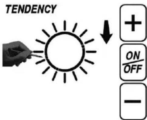
-
Touch the forecast icon and it will begin to flash. You can then use the + and - icons to manually change the upcoming forecast. You should only need to do this if the icon doesn't change automatically. The Tendency is affected by changes in barometric pressure, so changing it manually, if required will mean that the forecast begin to become more accurate in future.
-
Touch the forecast icon again and a value will now be displayed under the Pressure reading to the left. This value is the pressure threshold – changing this will affect how sensitive the station will be in regard to changes in barometric pressure. If you are in an area with stable pressure, you can lower this reading so that smaller changes in pressure are registered. Simply use the flashing + and - icons to adjust this value between 2-4 hPa as desired.
-
Pressing the forecast icon a final time will now allow you to change the storm threshold. Similarly, this will mean that a sudden change in pressure of a set value will be classified as a storm by the station. Change this value between 3-9 hPa using the + and - icons to the right.
Console Features Continued
Indoor Temperature:
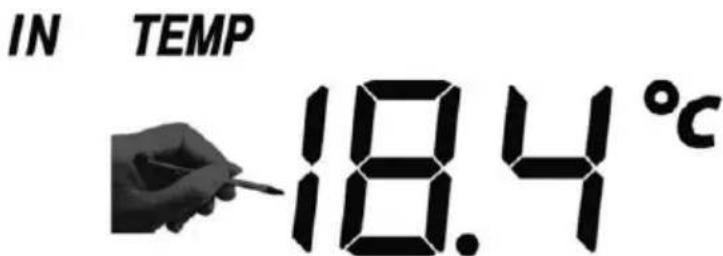
-
Touch the indoor temperature setting and it will begin flashing. You can now press the flashing + or - icons as normal to switch between units of measurement °C or °F.
-
Touch the indoor temperature again to access the high alarm function. You can use this to set a high alarm that will trigger once the indoor temperature has reached a certain figure. Set the desired value using the + or - keys, then press the 'ON/OFF' to activate or deactivate this setting as desired. If the alarm has been set, you will see the bell icon illuminated next to the indoor temperature reading.
-
Touch the indoor temperature a third time to access the low alarm function. You can use this to set a low alarm that will trigger once the indoor temperature has fallen to a certain figure. Set the desired value using the + or - keys, then press the 'ON/OFF' to activate or deactivate this setting as desired. If the alarm has been set, you will see the bell icon illuminated next to the indoor temperature reading.
-
Pressing the indoor temperature again will display the maximum record that has been measured. The 'MAX' icon will also be flashing in the lower-right segment of the screen. If you'd like to reset this record, push and hold the flashing digits for three seconds until this reverts to the current reading instead.
-
Pressing the indoor temperature for a fifth time will display the minimum record that has been measured. The 'MIN' icon will also be flashing in the lower-right segment of the screen. If you'd like to reset this record, push and hold the flashing digits for three seconds until this reverts to the current reading instead.
Console Features Continued
Outdoor Temperature:
OUT TEMP
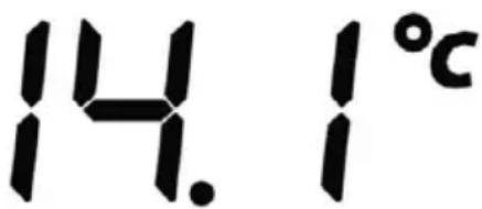
- Touch the outdoor temperature button and this value will begin flashing. You can now also press the + and - keys to scroll between Outdoor Temperature, Wind Chill and Dew Point.
- Touch the outdoor temperature again and you can now press the flashing + or - icons as normal to switch between units of measurement - either °C or °F.
- Touch the outdoor temperature again to access the high alarm function. You can use this to set a high alarm that will trigger once the outdoor temperature has reached a certain figure. Set the desired value using the + or - keys, then press the 'ON/OFF' to activate or deactivate this setting as desired. If the alarm has been set, you will see the bell icon illuminated next to the outdoor temperature reading.
- Touch the outdoor temperature a fourth time to access the low alarm function. You can use this to set a low alarm that will trigger once the outdoor temperature has risen to a certain figure. Set the desired value using the + or - keys, then press the 'ON/OFF' to activate or deactivate this setting as desired. If the alarm has been set, you will see the bell icon illuminated next to the outdoor temperature reading.
- Pressing the outdoor temperature again will display the maximum record that has been measured. The 'MAX' icon will also be flashing in the lower-right segment of the screen. If you'd like to reset this record, push and hold the flashing digits for three seconds until this reverts to the current reading instead.
- Pressing the outdoor temperature for a sixth time will display the minimum record that has been measured. The 'MIN' icon will also be flashing in the lower-right segment of the screen. If you'd like to reset this record, push and hold the flashing digits for three seconds until this reverts to the current reading instead.
Console Features Continued
Indoor Humidity:
-
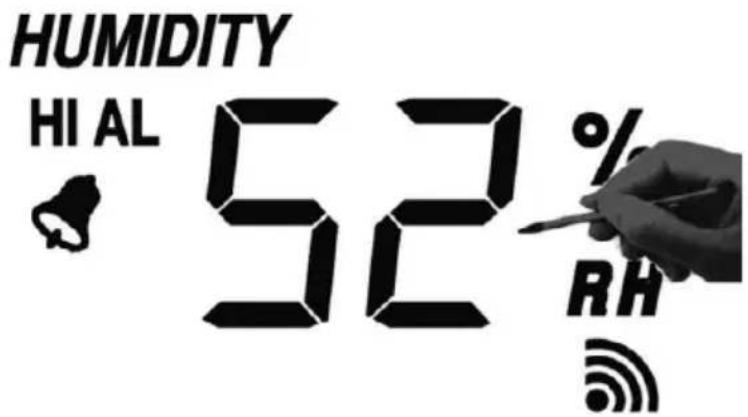
Touch the indoor humidity reading to use the high alarm function. You can now press the flashing + and - keys to adjust the desired figure, so that the alarm will sound once this level has been reached. Use the 'ON/OFF' number to enable/disable this alarm as desired – if the alarm is active the bell icon will be illuminated next to the indoor humidity reading.
-
Touch the indoor humidity reading again to access the low alarm function. This works in the same way as detailed above, use the + and - icons to adjust this figure and the 'ON/OFF' symbol to then enable the alarm.
-
Press the indoor humidity reading a third time to display the maximum indoor humidity recorded by the console. You can clear this record by pushing and holding the figure for three seconds until it reverts to the current reading.
-
Touch the indoor humidity reading a final time to view the minimum indoor humidity record. This can also be cleared by pushing and holding the value for three seconds.
Console Features Continued
Outdoor Humidity:

- Touch the outdoor humidity reading to use the high alarm function. You can now press the flashing + and - keys to adjust the desired figure, so that the alarm will sound once this level has been reached. Use the 'ON/OFF' number to enable/disable this alarm as desired, if the alarm is active the bell icon will be illuminated next to the outdoor humidity reading.
- Touch the outdoor humidity reading again to access the low alarm function. This works in the same as detailed above, use the + and - icons to adjust this figure and the 'ON/OFF' symbol to then enable the alarm.
- Press the outdoor humidity reading a third time to display the maximum outdoor humidity recorded by the console. You can clear this record by pushing and holding the figure for three seconds until it reverts to the current reading.
- Touch the outdoor humidity reading a final time to view the minimum outdoor humidity record. This can also be cleared by pushing and holding the value for three seconds.
EasyWeather PC Connection
Data Storage:
For a comprehensive weather history, the Base Station allows the internal storage of up to 4080 complete sets of weather data with time and date. The base station will lose all weather data if an interruption of power supply occurs. When the memory capacity of the Weather Station is exhausted the oldest data sets stored will be overwritten by new ones entering the system.
Data Recall:
Certain weather data or setting values can only be processed and displayed by means of a PC. This includes the settings for data storage intervals which can be set from between 5 minutes to 240 minutes by means of a PC.
Connections and Software:
The wiring between the Weather Station and PC takes place by means of an included USB cable. When connected full time to your PC the EasyWeather software package allows the display, storage, and printing of historic data sets; limited only by the capacity of the PC's main memory. When disconnected from a PC the Weather Station's memory can store 4080 data sets.
EasyWeather PC Software Connection
1.0 General Information:
After installing the EasyWeather program from the CD, you PC can display all indoor data as well as weather data received from the external weather sensors. For operation, simply use the USB cable supplied and connect the Weather Console to a PC's USB port.
EasyWeather PC Software Connection Continued
2.0 System Requirements:
To install the "EasyWeather" software onto your PC, the minimum requirements are as follows:
Operating System: Windows NT4 (Service Pack >= 6a), Windows 2000, Windows XP, Windows Vista. Windows 7, Windows 8, Internet Explorer 6.0 or above
Processor: Pentium III 500 MHz or above
Memory: at least 128MB, 256MB recommended
CD-ROM Drive
Base Station and PC must be connected by USB cable
3.0 Installation of the "EasyWeather" Software
Install the "EasyWeather" software as follows:
- Switch on your PC and insert the CD-ROM into the CD-ROM Drive.
- Double click ""Easyweather.exe""
- Select the installation process language option and click ok.
- Click next and select the destination folder (change directory when needed).
- Click next and select the shortcut folder (change directory when needed).
- Click next and select the additional tasks.
- Click next and setup is now ready to begin installing Easyweather on your computer.
- Click install, software will be installed automatically.
- Press Finish to finish the installation process and exit. If you tick "Launch Easy weather" the software will start to run.
- From "Start – All Programs – EasyWeather" double click the "Easy Weather" icon to start application.
Note: The graphic function needs the software to be installed under the administrator account. If it is installed under limited user accounts, the graphic function of the software might not be working correctly.
EasyWeather PC Software Connection Continued
4.0 Basic Settings of the "EasyWeather" Software:
After the "EasyWeather.exe" program has been started, the following main window will appear on the PC screen:

All settings from the weather console are mirrored in the PC software, if you have made setting changes on the weather console you will not need to make any amendments on the PC Software. You can still easily make any setting changes you want to from the PC and download these changes to the weather console (the setting change will be refreshed when the next full minute arrives on the base station).
If no weather console is connected to a PC, it shows "USB Connected" at the bottom of screen. If no base station is connected, it shows"USB Unconnected".
Tool Bar: The tool bar at the top of the screen has 4 options; System, Record Upload and Help:
EasyWeather PC Software Connection Continued
4.1 Tool Bar - System:
4.1.1 Clicking the System button, enters the Setting menu
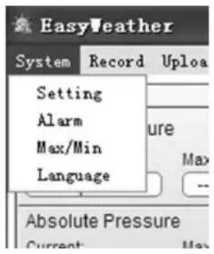

This section is used to set up the PC software display and base station units. Once you have made your choices press Save to make the setting effective.
EasyWeather PC Software Connection Continued
4.1.2 Clicking Alarm button, enters the Alarm menu

This section is used to set the desired time, high or low alarm value for the base unit, as well as enabling or disabling the corresponding alarm function. Once you have made your choice, choose Save for the setting to take effect. If you don't want to save any changes, just press Cancel and exit without change.
4.1.3 Clicking Max/Min button, enters the Max/Min menu
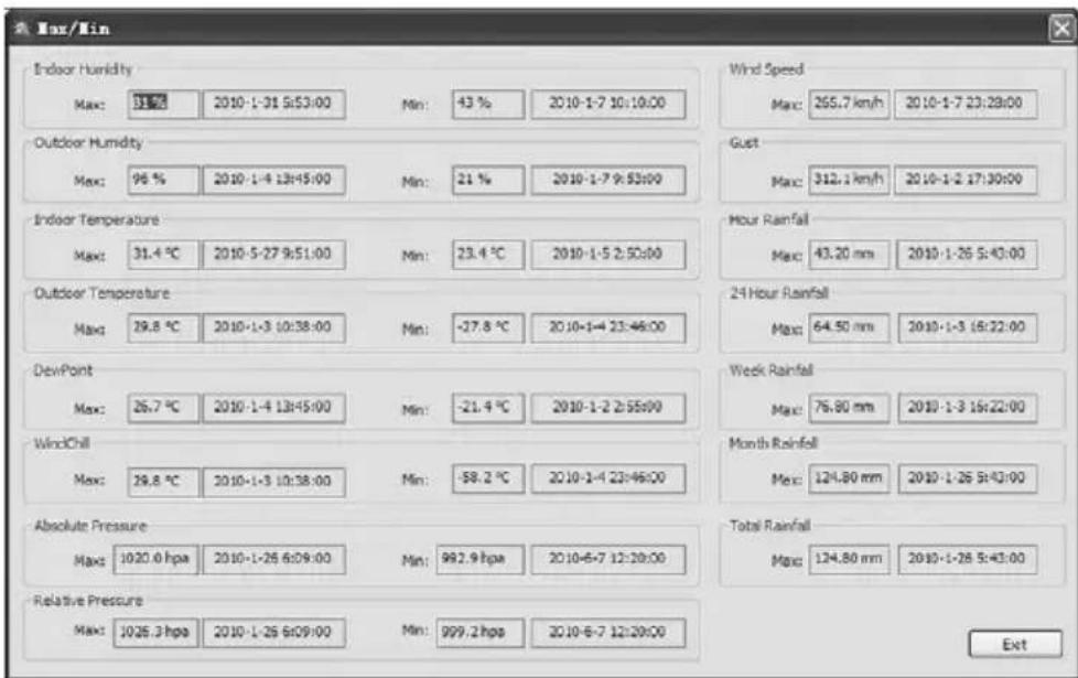
This section is used to display the recorded min and max value recorded with time stamp. Min/Max reset can only be done through key operation on the weather console.
EasyWeather PC Software Connection Continued
4.1.4 Clicking Language button, enters the Language menu

4.2 Tool Bar - Record:

4.2.1 Clicking History button, enters the History menu

EasyWeather PC Software Connection Continued
4.2.1 Clicking History button, enters the History menu continued
This section is used to display recorded history data in a spread sheet. If you wanted to see all history data in a desired time period, choose the time duration and press Search to reload the history data. With the Export button, you can export the selected history data into excel format file for other application purposes.
The software version 6.2 use .dat file format, the software version 6.2 or above uses .mdb format. Press the Import button, you can import an old version data to the new version data to migrate two different data base data.
When memory on base station is full, press "Clear Memory" button to empty the memory space on the weather console.
This option cannot be revered, so please only use it if you have uploaded your weather data to the EasyWeather software and are certain you want to clear the console of data!
If you wanted to start a new weather history record, press "Clear Data" button to delete the data base, ALL history weather data will be deleted. If you would like to keep a back up history file before deleting all weather data, you can make a copy of the "EasyWeather.mdb" file into another folder on your computer or just rename the "EasyWeather.mdb" file, such as "Jan-07.dat", for future reference.
EasyWeather PC Software Connection Continued
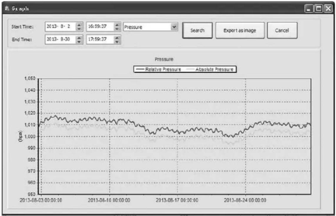
4.2.2 Clicking Graph button, enters the Graph menu
line
| Time | Relative Pressure (tpa) | Absolute Pressure (tpa) | | ------------------- | ------------------------ | ------------------------ | | 2013-08-03 00:00:00 | 1,015 | 1,010 | | 2013-08-10 00:00:00 | 1,012 | 1,008 | | 2013-08-17 00:00:00 | 1,005 | 1,003 | | 2013-08-24 00:00:00 | 1,010 | 1,007 |In this section you can see the history data plotted in graph format. If you want to see more detail, just use your mouse to select the area you want to see and the display will automatically update in a more detailed scale.

line
| Time | Relative Pressure | Absolute Pressure | | ----------------- | ----------------- | ----------------- | | 2013-08-03 00:00:00 | 1,010 | 1,010 | | 2013-08-10 00:00:00 | 1,015 | 1,015 | | 2013-08-17 00:00:00 | 1,005 | 1,005 | | 2013-08-24 00:00:00 | 1,012 | 1,012 |EasyWeather PC Software Connection Continued
4.2.2 Clicking Graph button, enters the Graph menu continued

line
| Time | Relative Pressure (Nps) | Absolute Pressure (Nps) | | ----------------- | ------------------------ | ------------------------ | | 2013-08-05 00:00:00 | 1.018 | 1.010 | | 2013-08-06 00:00:00 | 1.014 | 1.008 | | 2013-08-07 00:00:00 | 1.016 | 1.009 |With the Export as Image button, you can export the selected graph into .JPEG format file.
You can change the Y axis by scrolling the mouse up and down.
What to do if graph function is not working
This is the most frequently encountered problem with the EasyWeather software. To make sure the graph function works properly please check the following steps:
- Find the folder where the "EasyWeahter.exe" file is located
- Create a file name "reg_graph.bat" file with wordpad or notepad editor program
- Type "regsvr32 easyweather.ocx" and save the reg_graph.bat file
- Double click "reg_graph.bat" file and it should register the graphic driver again. If successful, then the following window will be displayed:

EasyWeather PC Software Connection Continued
4.3 Tool Bar - Upload:
4.3.1 Clicking Upload button, enters the upload menu
As a user you can upload data to the website www.wundergound.com


Note: How to create a Wunderground.com® account and station ID.
To join the wunderground.com® Community. Visit:
https://www.wundergro und.com/members/signup.asp
and sign up with wunderground.com®
To join the Personal Weather Station (PWS) network. Visit:
http://www.wunderground.com/weatherstation/about.asp
To add your weather station you will receive a Station ID. Enter the Station ID obtained and password you use to log into wunderground.com® site.
Please Note: Make sure you enter the ID in all capitals, and the password exactly as you have selected, both fields are case sensitive.
EasyWeather PC Software Connection Continued
4.4 Tool Bar - Help:
Clicking About EasyWeather button, enters the About menu
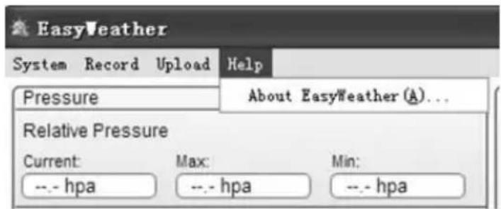
Notes about time synchronization between PC and sub-station:
The PC software obtains its own time scale through the time interval marker from the base station history data, and the PC software then automatically synchronizes the weather data with a time stamp calculated. Thus the history data file can have different time when the PC time and base station time are not same. In order to make the time scale correct, remember to set the PC time and base station time the same.
Remember to upload weather data to you PC periodically, i.e. before the memory capacity on the weather console is used up (memory icon on LCD display showing 100% full). Once the memory capacity on the weather console is full it is not possible to perform a data download and you will have to clear the console loosing all data.
Remember if there has been a rain fall readings reset on the weather console between downloads, then there will be rain fall value discrepancy between the PC and weather console readings.
Maintenance & Troubleshooting
The ClimeMET CM2000 has been designed with dependability in mind and will require minimal attention once set up. After the system has been installed, you should find that the only maintenance required will be an occasional check and clean of the sensors in order to ensure they provide you with years of service. This weather station uses 2 x AA batteries to power the outdoor sensor-suite - it will depend on the quality of the batteries used, but we'd normally expect these to last for around 12 months. At the same time you access the station to change the batteries, you may want to clean the sensors and carry out some brief checks.
If it appears that any problems are occurring with your weather station, please see the below guide for further information:
Display Console:
Outdoor data is not displaying and dashes are shown instead
Ensure that the outdoor sensor suite within range of the display console – the maximum range is 100 metres, or just over 300 feet. Please note that obstacles such as trees/walls/etc will have an impact on this communication range, so try to make sure the line of sight is as clear as possible.
Check that the batteries inside the sensor suite are not depleted – insert new batteries if you cannot be sure.
Indoor Temperature and Humidity:
Temperature readings are too high/low
If the indoor temperature readings appear to be high, make sure that the display console has not been placed in a location where it will be in direct sunlight during the day. This can cause the plastic casing to heat up which takes some time to cool down again, which may ultimately result in false readings. If the indoor temperature readings seem too low, check that the display console has not been mounted against an interior wall that cools down significantly throughout the day, as this could be affecting the readings measured. It's also worth checking that the console is not in the path of any air-conditioning units or located near an air vent. Similarly, make sure the outdoor sensor suite is not placed too close to surfaces that will radiate heat or affect nearby temperatures in a similar manner.
Maintenance & Troubleshooting Continued
Dew Point:
Dew Point figure appears to be incorrect
Dew point measurements depend upon the outdoor temperature and humidity figures, so it's vital to make sure that these readings are correct in order to calculate the dew point reading.
Wind:
Wind readings appear to be lower than expected
Wind readings can be significantly affected by the location of the system. Make sure that there is nothing in the surrounding area that could be shielding the CM2000 from the effects of the wind as this will reduce the strength of the readings received. Please remember that mounting the station a few feet higher or lower can alter the readings considerably.
Wind Chill:
Wind chill figure appears to be incorrect
Wind chill readings are reliant upon the wind speed and outdoor temperature measurements. If your wind chill readings appear to be inaccurate, please check these readings.
Specifications
Outdoor Data
| Transmission distance in open field:Frequency: | 100m (300 feet)433MHZ/868MHZ915MHz (North America) |
| Temperature range: -40C to 65C (-40°Fto +149°F)Accuracy: + / - 1 °CResolution: 0.1 °C | |
| Measuring range rel. humidity: 10%~99%Accuracy: +/- 5% | |
| Rain volume display: 0 - 9999mm (show --- if outside range)Accuracy: + / - 10%Resolution: 0.3mm (if rain volume < 1000mm)1mm (if rain volume > 1000mm) | |
| Wind speed: 0-160km/h (0~100mph)Accuracy: +/- 1m/s (wind speed< 10m/s) | (show --- if outside range)+/-10% (wind speed > 10m/s) |
| Measuring interval thermo-hygro sensor: 48 secWater proof level: IPX3 |
(E
Specifications Continued
Indoor Data
| Measuring interval pressure / temperature: 48 secIndoor temperature range: 0°C--50°C (32°Fto + 122°F)(show --- if outside range)Resolution: 0.1°C | |
| Measuring range rel. humidity: 10% 99%Resolution: 1% | |
| Measuring range air pressure: 300-1100hPa (8.85-32.5inHg)Accuracy: +/-3hpa under 700-1100hPaResolution: 0.1hPa (0.01inHg)Alarm duration: 20 sec |
Power consumption
| Base station: 2XAA 1.5V LR6 Alkaline batteriesRemote sensor: 2xAA 1.5V LR6 Alkaline batteriesBattery life: Minimum 12 months for base stationMinimum 24 months for thermo-hygro sensor |
Remark: where outdoor temperature is lower than -20^ , make sure to use the correct type of batteries to ensure the device can get enough power. Normal alkaline batteries do not function properly when outdoor temperature is lower then -20C as the battery discharge capability is greatly reduced.
ClimeMET
ClimeMET Ltd, 9 Church Field Road, Chilton Industrial Estate,
Sudbury, Suffolk, CO10 2YA
www.ClimeMET.com
ClimeMET
www.ClimeMET.com

natural_image
Exterior view of a weather station with sensors and antenna (no signage or text visible)

natural_image
Field of poppies in vibrant red, white, and orange flowers under a cloudy sky, with a vertical metal pole marker visible in the foreground.


- Welcome to the ClimeMET CM2000 Weather Station.
- This manual should be kept in a safe place for future reference as it contains important notes on the setup and operation of your weather station.
- Contents
- What's in the Box?
- You May Also Need:
- Please help in the preservation of the environment and return used batteries to an authorized depot.
- Base Station Features
- Base Station Features Continued
- The Sensor Suite
- Sensor Assembly
- Sensor Assembly Continued
- Getting Set Up
- Thermo-Hygro Transmitter:
- Display Console:
- Getting Set Up Continued
- Setting up with an Adaptor:
- Choosing Your Location
- Choosing Your Location Continued
- The Display Console Continued
- Console Features
- Time:
- Console Features Continued
- Memory:
- Date:
- Pressure:
- Pressure Bar:
- Tendency:
- OUT TEMP
- EasyWeather PC Connection
- Data Storage:
- Data Recall:
- Connections and Software:
- EasyWeather PC Software Connection
- General Information:
- EasyWeather PC Software Connection Continued
- System Requirements:
- Installation of the "EasyWeather" Software
- Basic Settings of the "EasyWeather" Software:
- Tool Bar - System:
- Clicking Alarm button, enters the Alarm menu
- Clicking Max/Min button, enters the Max/Min menu
- Clicking History button, enters the History menu continued
- This option cannot be revered, so please only use it if you have uploaded your weather data to the EasyWeather software and are certain you want to clear the console of data!
- Clicking Graph button, enters the Graph menu
- Clicking Graph button, enters the Graph menu continued
- What to do if graph function is not working
- Tool Bar - Upload:
- Tool Bar - Help:
- Notes about time synchronization between PC and sub-station:
- Maintenance & Troubleshooting
- Outdoor data is not displaying and dashes are shown instead
- Indoor Temperature and Humidity:
- Temperature readings are too high/low
- Maintenance & Troubleshooting Continued
- Dew Point figure appears to be incorrect
- Wind readings appear to be lower than expected
- Wind chill figure appears to be incorrect
- Specifications
- Specifications Continued
- ClimeMET
Brand : ClimeMET
Model : CM2000
Category : Weather Station