
VERTUS CLA 204T - Pregnant FBT - Free user manual and instructions
Find the device manual for free VERTUS CLA 204T FBT in PDF.


| Product Type | Loudspeaker for voice alarm system |
| Model | VERTUS CLA 204T |
| Certification | EN54-24, IP 21C (indoor installation) |
| Drivers | 2 x 4" woofer (1" voice coil), 1" HF dome driver |
| Recommended Amplifier Power | 80 W RMS |
| Line Transformer Taps (100V) | 30W, 20W, 10W, 5W |
| Line Transformer Taps (70V) | 30W |
| Low Impedance | 8 Ohm |
| Sensitivity | 88 dB (1W/1m) |
| Maximum Sound Pressure (SPL) | 103 dB at 1m / 91 dB at 4m |
| Frequency Response (-6 dB) | 130 Hz – 20 kHz |
| Horizontal Dispersion (-6 dB @ 2 kHz) | 120° |
| Vertical Dispersion (-6 dB @ 2 kHz) | 60° |
| Recommended High-Pass Filter | 110 Hz, 24 dB/oct |
| Enclosure Material | Extruded aluminium, powder coated |
| Input Connector | Ceramic screw block with thermal fuse |
| Net Weight | 3.4 kg (7.49 lb) |
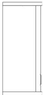
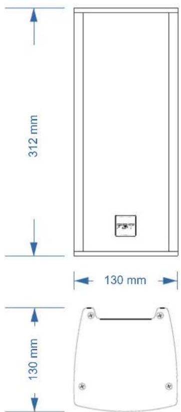
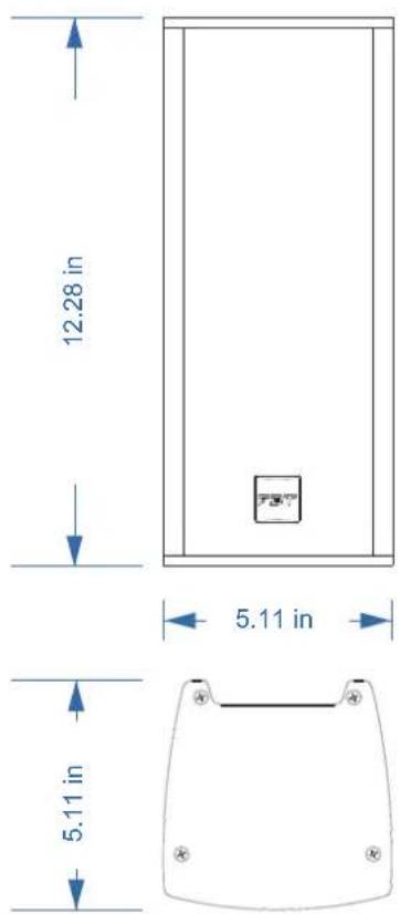
| Net Dimensions (W x H x D) | 130 x 312 x 130 mm (5.11 x 12.28 x 5.11 in) |
| Operating Temperature | -25°C to +55°C |
| Storage Temperature | -40°C to +70°C |
| Relative Humidity | < 95% |
| Color Options | Black and White |
| Mounting Accessories | Optional WM23 wall/ceiling mount stand |
| Application | Indoor voice alarm and emergency evacuation systems |
Frequently Asked Questions - VERTUS CLA 204T FBT
User questions about VERTUS CLA 204T FBT
0 question about this device. Answer the ones you know or ask your own.
Ask a new question about this device
Download the instructions for your Pregnant in PDF format for free! Find your manual VERTUS CLA 204T - FBT and take your electronic device back in hand. On this page are published all the documents necessary for the use of your device. VERTUS CLA 204T by FBT.
USER MANUAL VERTUS CLA 204T FBT
natural_image
Two white rectangular electronic devices with hexagonal patterns, labeled 'FBT' on their front panel (no additional text or symbols visible)FBT ELETTRONICA S.p.A.
Via Paolo Soprani 1 - 62019 RECANATI (MC) - ITALY
0068/CPR/***-2023
EN 54-24:2008
Loudspeaker for voice alarm system
for fire detection and fire alarm systems for buildings
CLA 203T
Type B
IP 55
CLA 204T
Type A
IP 21C

Declaration of Performance (DoP) available on the website www.fbt.it

natural_image
Isometric diagram of stacked 3D blocks with a circular label showing '4 LDPE' and a triangular symbol (no text or labels beyond the number)SACCHETTO
POLYETHYLENE
RACCOLTA PLASTICA
MANUALE
CARTA
RACCOLTA CARTA

natural_image
Line drawing of a rectangular device with a side-mounted bracket and mounting bracket (no text or symbols)CLA 204T
natural_image
Line drawing of a rectangular industrial device with a side-mounted bracket (no text or symbols)CLA 203T
CLA 203T:
CLA 203T
natural_image
Simple line drawing of a rectangular frame with a vertical line on the right side (no text or symbols)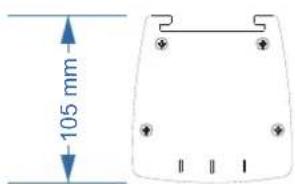
CLA 204T

natural_image
Blank rectangular frame with no text, numbers, or symbols| 6 | VITE ISO 14583 TCB M5 x 12 8.8 ZINC. | 2 |
| 5 | STAFFA SU DIFFUSORE | 1 |
| 4 | SNODO CENTRALE | 1 |
| 3 | PERNO SNODO ROTAZIONE ORIZZONTALE | 1 |
| 2 | STAFFA A MURO | 1 |
| 1 | SPINA CILINDRICA DIN 6325 DIAM. 8 x 18 | 1 |
| DESCRIZIONERIF. QTY. |
INSTALLAZIONE
natural_image
Technical line drawing of a cabinet or enclosure with internal components and mounting bracket (no text or symbols)Verticale
natural_image
Technical line drawing of a mechanical assembly with no visible text or symbols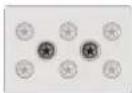
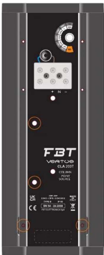
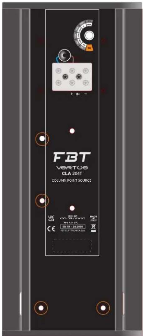
MORSETTIERA CERAMICA PER IL COLLEGAMENTO DELLE LINEE AUDIO (INGRESSO E USCITA)
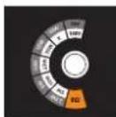
SELETTORE DELLE POTENZE

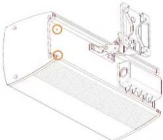
PUNTI DI FISSAGGIO DEL SUPPORTO WM23
IMPEDENZA TOTALE 8 OHM
| CLA 204T CLA 203T | ||
| CONFIGURAZIONE | 2 | 2 |
| POTENZA NOMINALE (100 hrs) | 40 (18 V RMS) 30 (15.5 V RMS) | |
| AMPLIFICATORE CONSIGLIATO | 80 W RMS 60 W RMS | |
| IMPEDENZA NOMINALE | 8 Ohm 8 Ohm | |
| IMPEDENZA NOMINALE (linea 100V) | 250 Ohm 30 W / 450 Ohm 20 W850 Ohm 10 W / 1650 Ohm 5 W | 250 Ohm 30 W / 450 Ohm 20 W850 Ohm 10 W / 1650 Ohm 5 W |
| IMPEDENZA NOMINALE (linea 70 V) | 125 Ohm 30 W | 125 Ohm 30 W |
| SENSIBILITÀ | 88 dB (@1W, 1m) 87 dB (@1W, 1m) | |
| MASSIMA PRESSIONE SONORA SPL | 103 / 91 dB (1m / 4m) 101 / 89 dB (1m / 4m) | |
| RISPOSTA IN FREQUENZA | 130 Hz - 20 kHz (@ -6 dB) 160 Hz - 20 kHz (@ -6 dB) | |
| LF WOOFER | 2 x 100 mm / bobina 25 mm 2 x 75 mm / bobina 20 mm | |
| DRIVER HF | 25 mm dome | 25 mm dome |
| DISPERSIONE ORIZZONTALE (-6dB) | 500 Hz - 220°1 kHz - 170°2 kHz - 120°4 kHz - 140°8 kHz - 85° | 500 Hz - 360°1 kHz - 170°2 kHz - 120°4 kHz - 140°8 kHz - 100° |
| DISPERSIONE VERTICALE (-6dB) | 500 Hz - 165°1 kHz - 70°2 kHz - 130°4 kHz - 140°8 kHz - 80° | 500 Hz - 200°1 kHz - 90°2 kHz - 110°4 kHz - 50°8 kHz - 120° |
| FILTRO HP CONSIGLIATO 110 Hz - | 24 dB oct. 140 Hz - 24 dB oct. | |
| CONNETTORE DI INGRESSO | morsettiera ceramica | morsettiera ceramica |
| TEMPERATURA D'ESERCIZIO / STOCCAGGIO | -25°C + +55°C / -40°C + +70°C | -25°C + +55°C / -40°C + +70°C |
| UMIDITÀ RELATIVA | < 95% | < 95% |
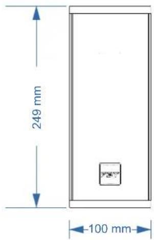
| DIMENSIONI NETTE | 130 x 312 x 130 mm 100 x 249 x 105 mm( L x A x P ) | |
| PESO NETTO | 3,4 kg 1,5 kg |
GENERAL INFORMATIONS
VERTUS CLA 203T / 204T
Version 1.1 ITA/EN - 07/2023
Keep this document in a safe place so that it is available for future reference.
We recommend you to regularly check the FBT website for the latest version of this document.
FBT Elettronica SpA - 62019 RECANATI (Italy)
- info@fbt.itwww.fbt.it

Where affixed on the equipment or package, the barred waste bin sign indicates that the product must be separated from other waste at the end of its working life for disposal. At the end of use, the user must deliver the product to a suitable recycling centre or return it to the dealer when purchasing a new product. Adequate disposal of the decommissioned equipment for recycling, treatment and environmentally compatible disposal contributes in preventing potentially negative effects on the environment and healt and promotes the reuse and/or recycling of equipment materials. Abusive product disposal by the user is punishable by law with administrative sanctions.
MASTER CARTON
PAPER
PAPER DISPOSAL
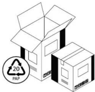
natural_image
Illustration of two cardboard boxes with a 20% PAP recycling symbol (no text or labels on the boxes themselves)INTERNAL PROTECTIONS
POLYETHYLENE
PLASTIC DISPOSAL
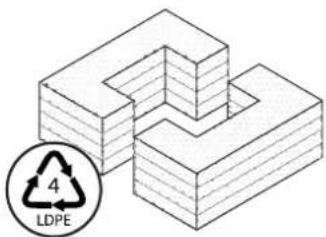
natural_image
Isometric diagram of stacked 3D blocks with a circular LDPE symbol (no text or labels)BAG
POLYETHYLENE
PLASTIC DISPOSAL
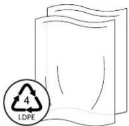
MANUAL
PAPER
PAPER DISPOSAL

Avoid release to the environment
Check the instructions of your municipality Separate the components and arrange them properly


WARNING
RISK OF ELECTRIC SHOCK DO NOT OPEN

- Loudspeaker lines (amplifier outputs) can have a sufficiently high voltage (i.e. 100V) to involve a risk of electrocution; never install or connect this loudspeaker when the line is alive.
- Make sure all connections have been made correctly and the loudspeaker input voltage (in a constant voltage system) or its impedance is suitable for the amplifier output.
- Protect loudspeaker lines from damage; make sure they are positioned in a way that they cannot be stepped on or crushed by objects.
- To prevent inductive effects from causing hum, noise and a bad system working, loudspeaker lines should not be laid together with other electric cables (mains), microphone or line level signal cables connected to amplifier inputs.
- Never attempt to carry out any operations, modifications or repairs that are not expressly described in this manual. Contact your authorized service centre or qualified personnel.
- Also check the suitability of the support surface to which the product is anchored (wall, ceiling, structure, etc.) and the components used for attachment (screws, screw anchors, etc.).
- Use only the optional devices / accessories specified by the manufacturer.
- Never use the handles, brackets or other elements of the module to directly suspend the modules or the system.
- All informations included in this operating manual have been scrupulously controlled; however FBT is not responsible for eventual mistakes.
- FBT Elettronica SpA has the right to amend products and specifications without notice.
TO REDUCE THE RISK OF ELECTRIC SHOCK DO NOT REMOVE COVER (OR BACK) NO USER SERVICEABLE PARTS INSIDE REFER SERVICING TO QUALIFIED SERVICE PERSONNEL. TO REDUCE THE RISK OF FIRE OR ELECTRIC SHOCK DO NOT EXPOSE THIS EQUIPMENT TO RAIN OR MOISTURE.
This manual contains important about the correct and safe use of the device. Before connecting and using this product please read this instruction manual carefully and keep it on hand for future reference. The manual is to be considered an integral part of this product and must accompany it when it changes ownership as a reference for correct installation and use as well as for the safety precautions. FBT SpA will not assume any responsibility for the incorrect installation and/or use of this product.
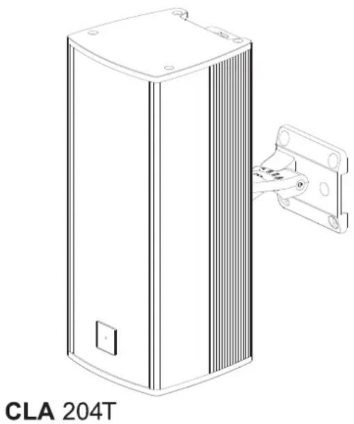
natural_image
Line drawing of a rectangular electronic device with a bracket and mounting bracket, labeled 'CLA 204T' below (no other text or symbols)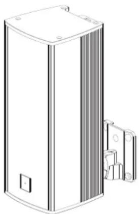
natural_image
Line drawing of a rectangular electronic device with a side bracket and mounting bracket (no text or symbols)CLA 203T
FBT introduces two new VERTUS models: CLA 204T and CLA 203T. Built in aluminum extrusion and IP55 certified weather resistant (only CLA 203T model): waterproof enclosure, waterproof treated loudspeakers, grille with hydrophobic fabric, hermetic terminal box.
FBT CLA 204T and FBT CLA 203T are also EN54-24 certified for emergency and evacuation systems: the ceramic terminal block and thermal fuse guarantee protection to the line connection in the event of fire.
Sleek and elegant lines distinguish the design of these new VERTUS models. A series of accessories completes the offer for optimal use of the product.
CLA 204T:
- 2 x 4" woofer with 1" coil
- 1" HF dome driver
• Recommended amplifier 80W RMS
• Line transformer 70/100V with power selector - Dispersion angle @ 2 kHz: 120^ O x 60^ V
- Internal crossover
• Extruded aluminium powder coated enclosure - Ceramic screw block connector with thermal fuse
- Multiangle speaker wall stand (optional)
• EN54-24 certification
• IP 21C rating for indoor installation
• Available in black and white
EXTERNAL PROCESSING IS NECESSARY TO IMPROVE SOUND BALANCE AND RELIABILITY OF THE TRANSDUCERS. OFFICIAL FBT PRESET MUST BE USED. SEARCH FOR AVAILABILITY ON THE FBT WEBSITE OR ASK YOUR DEALER.
CLA 203T:
- 2 x 3" woofer with 0.75" coil
- 1" HF dome driver
- Recommended amplifier 60W RMS
• Line transformer 70/100V with power selector - Dispersion angle @ 2 kHz: 125^ O × 70^ V
- Internal crossover
• Extruded aluminium powder coated enclosure - Front grid with hydrophobic cloth
- Ceramic screw block connector with thermal fuse
- Multiangle speaker wall stand (optional)
• EN54-24 certification
• IP 55 rating for outdoor installation
• Available in black and white
EXTERNAL PROCESSING IS NECESSARY TO IMPROVE SOUND BALANCE AND RELIABILITY OF THE TRANSDUCERS. OFFICIAL FBT PRESET MUST BE USED. SEARCH FOR AVAILABILITY ON THE FBT WEBSITE OR ASK YOUR DEALER.
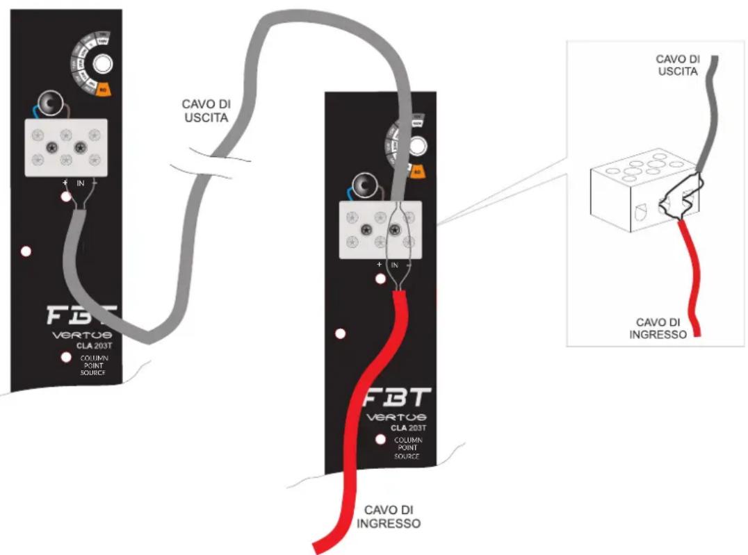
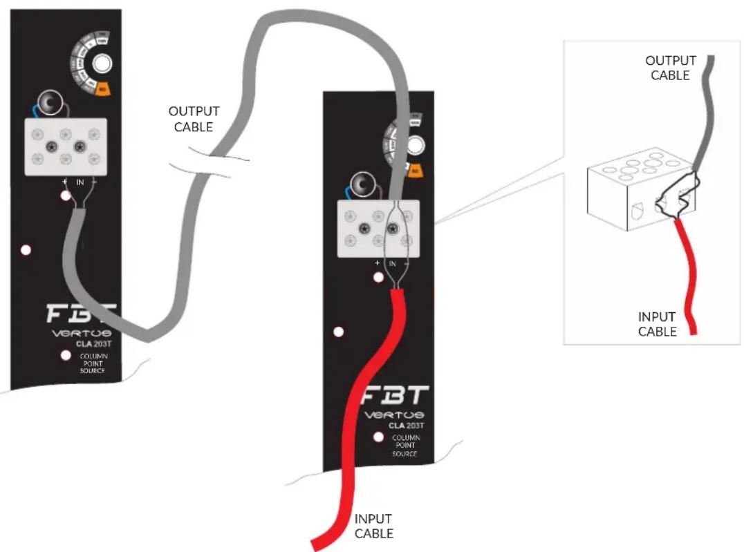
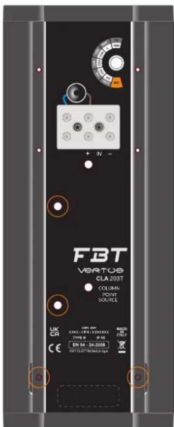
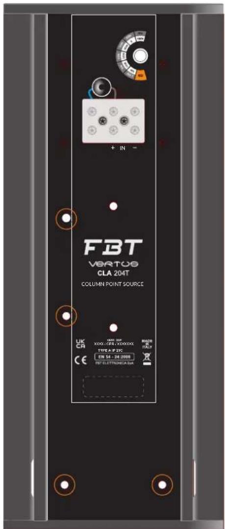
Connections with the audio line are made using the ceramic connector included in the protective casing "A".
The two screw clamps "+" and "-" allow the connection of both the input cable and output cable for the parallel connection of other speakers.
For 70 / 100 V constant voltage lines position the selector on the desired power value; for the low impedance connection position the selector on "8 Ohm".
CAUTION: Do not position the selector on low impedance mode (8 Ohm) when the speaker is connected in constant voltage mode (70 / 100V).
CAUTION: For the CLA 203T model after making the connections and necessary adjustments, it is STRICTLY NECESSARY to reposition the protective casing "A".

IMPORTANT NOTES ON CABLES
To connect the speakers VERTUS CLA 203T / CLA 204T in an EVAC emergency evacuation system use a CEI 20-105 approved cable.. To install the speakers outdoors (model CLA 203T) it is strictly necessary to use a cable with overall diameter 6-9 mm in order to guarantee the system's impermeability (CAUTION: tighten the cable gland properly).
To make a "link" use a PG9 cable gland in a material with self-extinguishing rating 94V0 and protection rating IP 68.
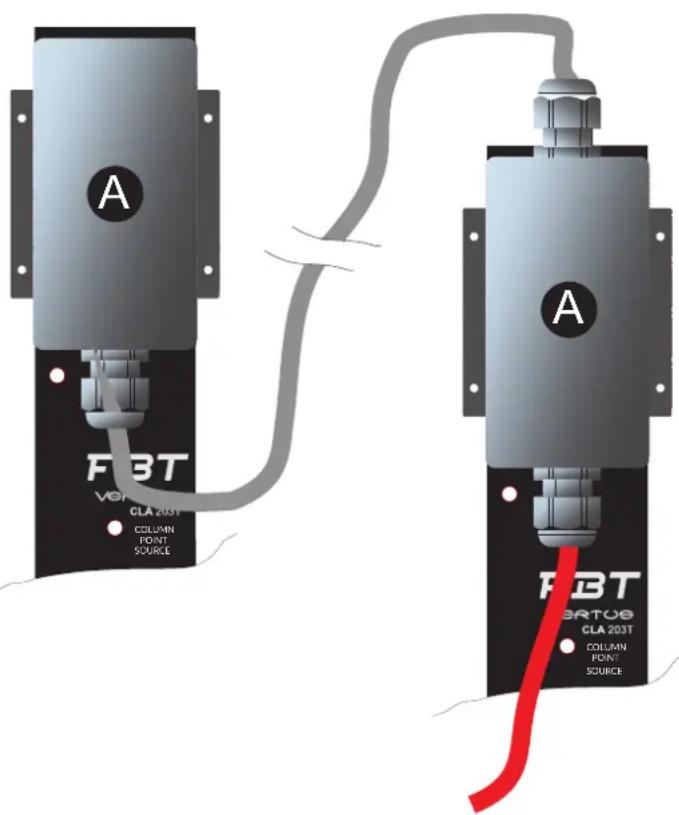
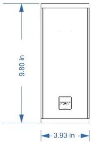
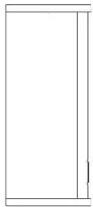
CLA 203T
natural_image
Simple line drawing of a rectangular frame with a vertical divider and a small mark on the right side (no text or symbols)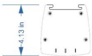
CLA 204T

natural_image
Blank rectangular frame with no text, numbers, or symbols- VERTUS sound speakers must be installed using the flying accessories described in this manual and following the special assembly instructions by qualified staff only, strictly complying with the current regulations and safety standards in force in the country of installation.
- FBT flying accessories are manufactured for their exclusive use with VERTUS systems and have not been designed for being used with any other speaker or device.
- Any possible element of the ceiling, floor or further support where VERTUS systems are to be installed shall be able to safety bear the load.
- The flying accessories in use are to be coupled and secured safety to both the sound speaker and the ceiling or the other support. When components are fitted to ceilings, floors or beams, always make sure that all couplers and fixing elements are properly sized and have an adequate load capacity.
- Besides the main suspension system, all flying speakers in theatres, indoor stadiums or in several other work and/or leisure facilities shall be provided with an additional independent safety system with the adequate load capacity.
- As for fixed installations, always schedule and carry out special inspections on a regular basis in order to check all the parts that have to guarantee system safety over time.
- The VERTUS speakers use only with FBT mount for wall installation. Use with other mounts is capable of resulting in instability causing possible injury.
- FBT Elettronica SpA will not be held liable for damage or injuries caused by supports or structures which are not sufficiently sturdy or by incorrect installation.
WM23 SPEAKER WALL / CEILING MOUNT STAND FOR VERTUS CLA 203T E VERTUS CLA204T MODELS
PRECAUTIONS
- This speaker stand can ONLY be used with a speaker that weighs less than 8,81 lbs.
- Check to make sure that the mounting surface (wall or ceiling) can fully support the combined weight of the speaker and bracket before installation.
- Make sure to tighten each screw and bolt securely. After installation check that each screw and bolt are free from looseness and that the speaker system is securely fixed.
- When adjusting the speaker angle or direction, be sure to loosen the applicable rotation locks screw or joint bolt first.
- FBT accepts no liability for any injury or damage resulting from improper selection of the mounting position, improper installation or misuse of the product.
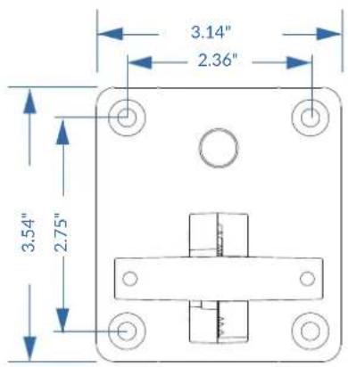
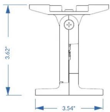
DIMENSIONS
Available in black and white

Code: 45783 Code: 65782
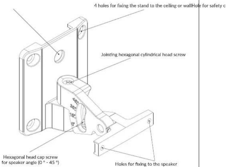
CONSTRUCTION DIAGRAM
EXPLODED DIAGRAM
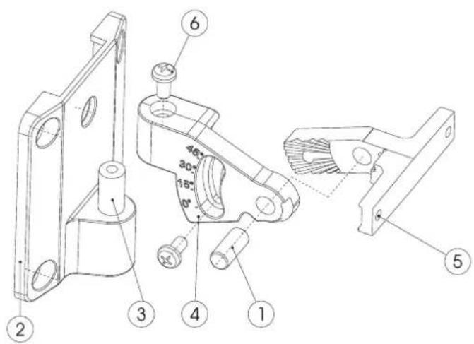
| 6 | SCREW ISO 14583 TCB M5x12 8.8 ZINC. | 2 |
| 5 | BRACKET ON SPEAKER | 1 |
| 4 | CENTRAL JOINT | 1 |
| 3 | HORIZONTAL ROTATION JOINT PIN | 1 |
| 2 | WALL BRACKET | 1 |
| 1 | CYLINDRICAL PIN DIN 6325 DIAM. 8 x 18 | 1 |
| DESCRIPTIONREF. QTY. |
INSTALLATION
The WM 23 stand consists of two parts. To facilitate assembly use the cardboard template included in the package to precisely mark the four fixing points.
- Remove the joint screw (B) and fix only the part of the stand that will go to the wall (M5 screws are recommended).
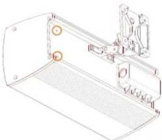
- Attach the other part of the stand to the speaker and then hook the whole system.
- Tighten the connecting screw.
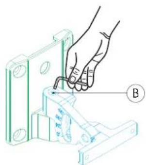
Fig 1
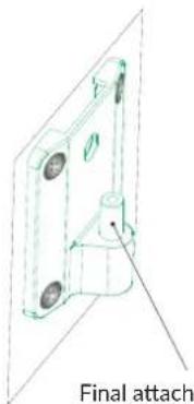
Final attachment point

natural_image
Technical line drawing of a mechanical or electrical enclosure with internal components and mounting bracket (no text or symbols)Vertical
natural_image
Technical line drawing of a mechanical housing or enclosure with mounting holes and internal components (no text or symbols)Horizontal
○ All possible hooks holder to the speaker
SPEAKER ANGLE ADJUSTMENT
The stand can be adjusted so that the speaker is set for the desired listening position.
- Rotation lock screw: Use the hexagonal wrench to loosen the rotation lock screw (A), then set the speaker to the desired angle (da 0° a 45°) and retighten securely. ATTENTION: Do not try to move without loosening the rotation lock screw.
- Joint screw: Using the hexagonal wrench to loosen the joint screw (B) (fig.1), set the speaker to the horizontal desired angle and then retighte the joint screw.
SAFETY CABLE AND POWER CORD
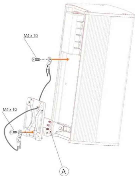
Use the M4 x 10 screws (supplied) to attach the safety cable.
All rights reserved, unauthorized reproduction, modification or production of any portion of this document is forbidden.
FBT products are continually improved. All specifications are therefore subject to change without notice..
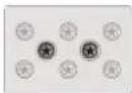
CERAMIC TERMINAL BLOCK FOR
CONNECTING THE AUDIO LINES
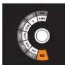
POWER SELECTOR

FIXING POINTS OF THEWM23 SUPPORT
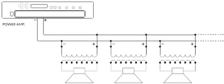
CONSTANT VOLTAGE CONNECTION
This connection system requires that each speaker be equipped with a dedicated line transformer. The amplifier must have steady voltage outputs of 100V or 70V. Should it be necessary, the loudspeakers connected in parallel to the output of the amplifier allow you to extend the installation from any of the previously installed speakers, and also to remove the loudspeakers when no longer needed. When making the connections, you have to observe the "phase" of speaker connection to its own transformer and also that of the parallel connection of the speakers. The input voltage of the speaker must match the output voltage of the amplifier; the total rating power of all speakers connected to the line must not be greater than that of the amplifier.
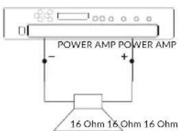
LOW IMPEDANCE CONNECTION
This type of connection does not allow limiting the power of each speaker individually, because it was designed to obtain greater performance. The main rule to be observed is that the total impedance of the speakers is equal to or greater than that of the amplifier. If you use one speaker, pairing takes place istantly, but if you are using several speakers, the impedance value will be added or divided according to the type of connection (series or parallel). As long as you use just a few speakers, it will be easy to get the 4, 8, 16 Ohm required by ordinary amplifiers, but if you use more speakers, you will have to use a combined series/parallel connection to reduce the total impedance of the loudspeakers to a value that will not be critical for the amplifier. When carrying out the steady impedance connection, you should always make sure that the total power of the speakers installed is greater than that output by the amplifier so as to prevent any damage due to overload, if the output power is close to the rated power. In this case the impedance of a single speaker is 16 ohms; parallel connection of two loudspeakers results in a total impedance of 8 Ohn (impedance=16/number of loudspeakers)
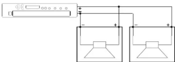
TOTAL IMPEDANCE 8 OHM
| CLA 204T CLA 203T | ||
| CONFIGURATION | 2 | 2 |
| RATED NOISE POWER (100 hrs) | 40 (18 V RMS) 30 (15.5 V RMS) | |
| RECOMMENDED AMPLIFIER | 80 W RMS 60 W RMS | |
| NOMINAL IMPEDANCE | 8 Ohm 8 Ohm | |
| NOMINAL IMPEDANCE (100V line) | 250 Ohm 30 W / 450 Ohm 20 W850 Ohm 10 W / 1650 Ohm 5 W | 250 Ohm 30 W / 450 Ohm 20 W850 Ohm 10 W / 1650 Ohm 5 W |
| NOMINAL IMPEDANCE (70V line) | 125 Ohm 30 W 125 Ohm | 30 W |
| SENSITIVITY | 88 dB (@1W, 1m) 87 dB (@1W, 1m) | |
| MAX SOUND PRESSURE (SPL) | 103 / 91 dB (1m / 4m) 101 / 89 dB (1m / 4m) | |
| FREQUENCY RESPONSE | 130 Hz - 20 kHz (@ -6 dB) 160 Hz - 20 kHz (@ -6 dB) | |
| LF WOOFER | 2 x 4" / 1" coil 2 x 3" / 0.75" coil | |
| DRIVER HF | 1" dome | 1" dome |
| HORIZONTAL DISPERSION (-6dB) | 500 Hz - 220°1 kHz - 170°2 kHz - 120°4 kHz - 140°8 kHz - 85° | 500 Hz - 360°1 kHz - 170°2 kHz - 120°4 kHz - 140°8 kHz - 100° |
| VERTICAL DISPERSION (-6dB) | 500 Hz - 165°1 kHz - 70°2 kHz - 130°4 kHz - 140°8 kHz - 80° | 500 Hz - 200°1 kHz - 90°2 kHz - 110°4 kHz - 50°8 kHz - 120° |
| RECOMMENDED HP FILTER 110 Hz - 24 dB oct. 140 Hz - 24 dB oct. | ||
| INPUT CONNECTOR | ceramic block | ceramic block |
| OPERATING/STORAGE TEMPERATURE | -25°C ÷ +55°C / -40°C ÷ +70°C | -25°C ÷ +55°C / -40°C ÷ +70°C |
| RELATIVE HUMIDITY | < 95% | < 95% |
| NET DIMENSIONS (W x H x D) | 5.11 x 12.28 x 5.11 inch 3.93 x 9.80 x 4.13 inch | |
| NET WEIGHT | 7,49 lb 3,30 lb | |
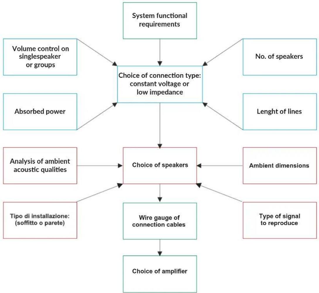
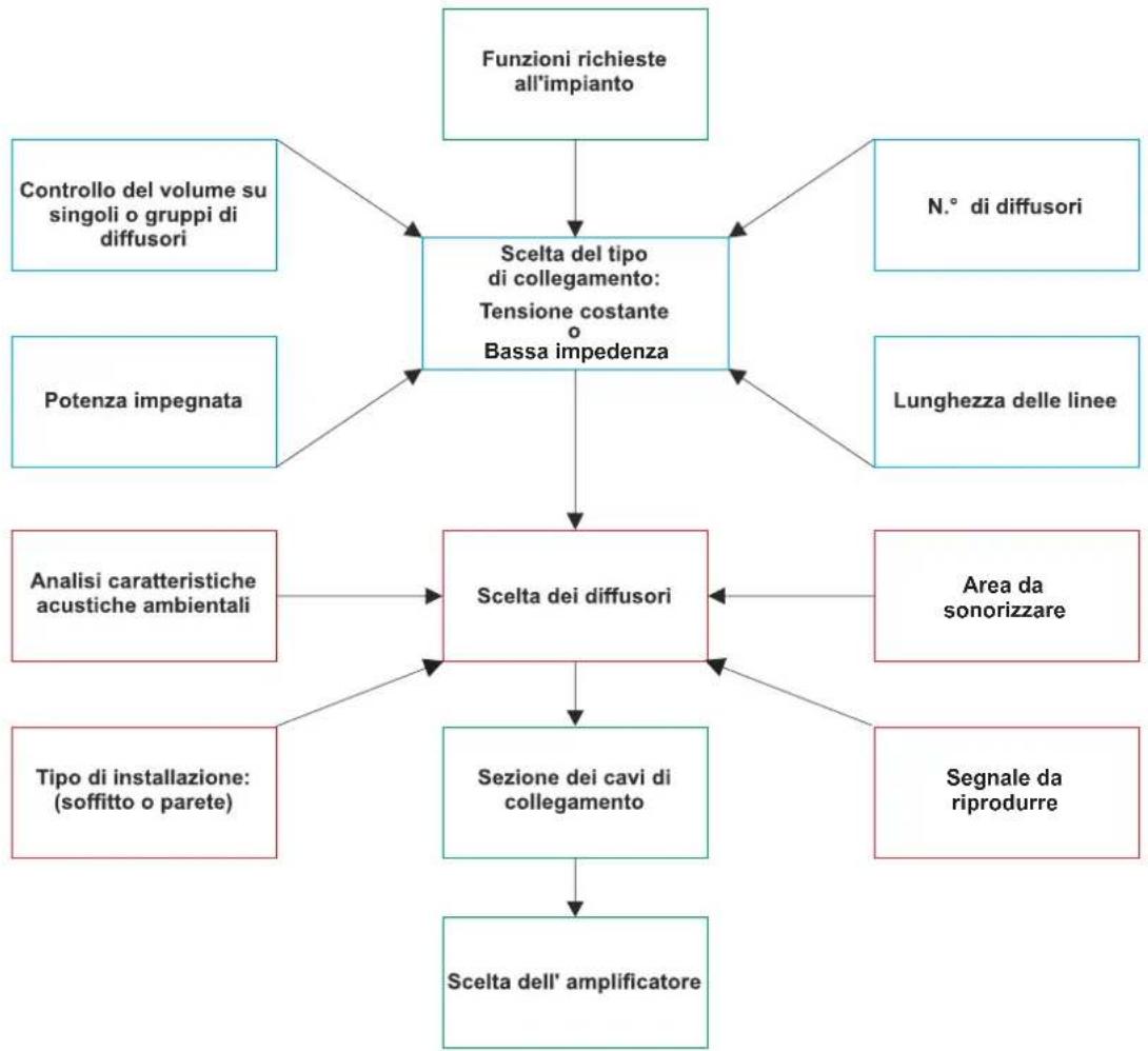
flowchart
graph TD
    A["Choice of connection type: constant voltage or low impedance"] --> B["Volume control on singlespeaker or groups"]
    A --> C["No. of speakers"]
    A --> D["Absorbed power"]
    A --> E["Lenght of lines"]
    A --> F["Analysis of ambient acoustic qualities"]
    A --> G["Ambient dimensions"]
    A --> H["Tipo di installazione: (soffitto o parete)"]
    A --> I["Type of signal to reproduce"]
    A --> J["Choice of speakers"]
    J --> K["Wire gauge of connection cables"]
    K --> L["Choice of amplifier"]
WALL APPLICATIONS
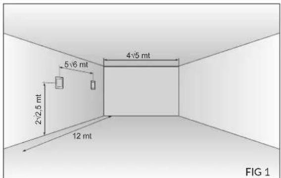
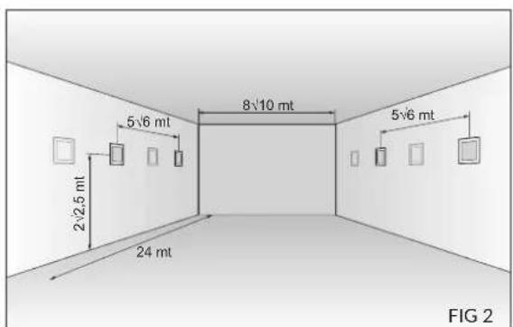
If the architectural features of the room are not compatible with a ceiling configuration or if a wall application is preferred, it is essential to observe a few basic rules to obtain the best possible sound distribution. In order to maintain the listening point inside the direct signal area, both surface mounted and external speakers, with power from 6 to 20 W, should be installed at a height of between 2 and 2.5 m. The maximum distance between adjacent speakers must be no more than 5/6 metres along the length of the room, which should be no wider than 4/5 metres.
For wider rooms, e.g. about 8-10 metres, it is recommended to install speakers in an alternated pattern along both the opposing walls in such a way as to provide adequate coverage and maintain sound pressure at the most constant possible level in the area in question (see figures 1 and 2). A quick and approximate calculation can be made of distance "d" which separates the centres of two speakers, when the angle of emission "A" and height of the ceiling "H" is known: d = 2 "(H-1)" "B", where "H" is the height of the ceiling expressed in feet, constant "1" is the height of the listening surface of a seated person and "B" is the tangent of "A" / 2.
From the above data, it is evident that for the same ceiling height "H", speakers with wider dispersion angles offer a larger sound diffusion area and therefore a smaller number of speakers are effectively needed.

- CLA 203T:
- INSTALLAZIONE
- GENERAL INFORMATIONS
- MASTER CARTON
- INTERNAL PROTECTIONS
- BAG
- MANUAL
- WARNING
- CLA 204T:
- IMPORTANT NOTES ON CABLES
- WM23 SPEAKER WALL / CEILING MOUNT STAND FOR VERTUS CLA 203T E VERTUS CLA204T MODELS
- PRECAUTIONS
- INSTALLATION
- SPEAKER ANGLE ADJUSTMENT
- SAFETY CABLE AND POWER CORD
- CONSTANT VOLTAGE CONNECTION
- LOW IMPEDANCE CONNECTION
- WALL APPLICATIONS
Brand : FBT
Model : VERTUS CLA 204T
Category : Pregnant