
PX 4116 - Telephone RCF - Free user manual and instructions
Find the device manual for free PX 4116 RCF in PDF.


| Product Type | UHF Wireless Microphone System (Bodypack) |
| Frequency Band | UHF 638 – 662 MHz |
| Number of Channels | 120 (10 groups of 12 frequencies) |
| Receiver Type | RX 4016 PLL UHF Diversity Receiver |
| Transmitter Type | PX 4100 Bodypack Transmitter |
| RF Output Power (Selectable) | 1 mW (PL0), 3 mW (PL1), 10 mW (PL2) |
| Balanced Audio Output | XLR, 1 V max (selectable 500 mV, 300 mV, 150 mV) |
| Unbalanced Audio Output | 6.3 mm TS jack, 750 mV |
| Frequency Response (System) | 50 Hz – 50 kHz (±3 dB) |
| Receiver Power Supply | External 15 V DC adapter (0.5 A, included) |
| Transmitter Power Supply | 2 × AA non-rechargeable batteries (1.5 V) |
| Included Microphone | LA 2004 Lavalier (tie-clip) electret microphone |
| Diversity System | Smart switching diversity with two antennas |
| Auto-Scan Function | Automatic search for transmitter frequency |
| Squelch Control | Adjustable threshold (10 levels, -95 dB to -65 dB) |
| Lock Function | Protects settings from accidental changes |
| Mute Function | Mutes audio on receiver or transmitter |
| Safety Features | Overload protection, no liquids, use only supplied adapter |
| Compliance | CE certified |
Frequently Asked Questions - PX 4116 RCF
User questions about PX 4116 RCF
0 question about this device. Answer the ones you know or ask your own.
Ask a new question about this device
Download the instructions for your Telephone in PDF format for free! Find your manual PX 4116 - RCF and take your electronic device back in hand. On this page are published all the documents necessary for the use of your device. PX 4116 by RCF.
USER MANUAL PX 4116 RCF
OWNER MANUAL MANUALE D'USO
TX 4016 PX 4116
- UHF DIVERSITY WIRELESS MICROPHONES
- RADIOMICROFONI UHF "DIVERSITY"
INDEX INDICE

ENGLISH
SAFETY PRECAUTIONS
DESCRIPTION
RX 4016 RECEIVER RACK MOUNTING
RX 4016 FRONT PANEL
RX 4016 REAR PANEL
RX 4016 OPERATION
TX 4000 TRANSMITTER / HANDHELD DYNAMIC MICROPHONE 11
PX 4100 BODY PACK TRANSMITTER | 12
TX 4000 / PX 4100 TRANSMITTER OPERATION 13
FREQUENCIES 15
SPECIFICATIONS 16
ITALIANO
AVVERTENZEPERLASICUREZZA 18
DESCRIZIONE 20
INSTALLAZIONE A RACK (19") DEI RICEVITORI RX 4016 21
RX 4016 – PANNELLO FRONTALE 21
RX 4016 - PANNELLO POSTERIORE 22
FUNZIONAMENTO DEL RICEVITORE RX 4016 | 23
TRASMETTITORE AD IMPUGNATURA TX 4000 CON MICROFONO DINAMICO 25
TRASMETTITORE PER CINTURA PX 4100 26
Before connecting and using this product, please read this instruction manual carefully and keep it on hand for future reference. The manual is to be considered an integral part of this product and must accompany it when it changes ownership as a reference for correct installation and use as well as for the safety precautions.
RCF S.p.A. will not assume any responsibility for the incorrect installation and / or use of this product.
WARNING: To prevent the risk of fire or electric shock, never expose these products to rain or humidity.
SAFETY PRECAUTIONS
-
All the precautions, in particular the safety ones, must be read with special attention, as they provide important information.
-
Use the dedicated adapter only. Verify the mains voltage corresponds to the voltage shown on the adapter rating plate and the adapter output voltage value and type (direct / alternating) corresponds to the product input voltage. If not, please contact your RCF dealer.
Check also that the adapter has not been damaged due to possible clashes / hits or overloads.
The mains voltage, which the adapter is connected to, is sufficiently high to involve a risk of electrocution: pay attention during the connection (i.e. never do it with wet hands) and never open the adapter.
Make sure that the adapter cable is not (or cannot be) stepped on or crushed by other objects (pay particular attention to the cable part near the plug and the point where it leads out from the adapter).
- Make sure that no objects or liquids can get into these products, as this may cause a short circuit.
All devices shall not be exposed to dripping or splashing. No objects filled with liquid (such as vases) and no naked sources (such as lighted candles) shall be placed on receivers.
- Never attempt to carry out any operations, modifications or repairs that are not expressly described in this manual.
Contact your authorized service centre or qualified personnel should any of the following occur:
- The product does not function (or functions in an anomalous way)
- The adapter or its power supply cable has been damaged
- Objects or liquids have got into the unit
- The product has been subject to a heavy impact.
-
If this product is not used for a long period, unplug the receiver adapter and remove all batteries from the transmitter.
-
If a product begins emitting any strange odours or smoke, switch it off immediately, unplug the receiver adapter and/or remove batteries from the transmitter.
-
Do not connect this product to any equipment or accessories not foreseen.
Check the suitability of the surface on which the receiver is placed, considering (for example) the mechanical vibrations normally generated by transducers.
To prevent the risk of falling equipment, do not stack more receivers.
- RCF S.p.A. strongly recommends this product is only installed by professional qualified installers (or specialised firms) who can ensure correct installation and certify it according to the regulations in force. The entire audio system must comply with the current standards and regulations regarding electrical systems.
IMPORTANT NOTES

WARNING

- Supports and trolleys
The equipment should be only used on trolleys or supports, where necessary, that are recommended by the manufacturer.
The equipment / support / trolley assembly must be moved with extreme caution.
Sudden stops, excessive pushing force and uneven floors may cause the assembly to overturn.
-
There are numerous mechanical and electrical factors to be considered when installing a professional audio system (in addition to those which are strictly acoustic, such as sound pressure, angles of coverage, frequency response, etc.).
-
Hearing loss
Exposure to high sound levels can cause permanent hearing loss.
The acoustic pressure level that leads to hearing loss is different from person to person and depends on the duration of exposure. To prevent potentially dangerous exposure to high levels of acoustic pressure, anyone who is exposed to these levels should use adequate protection devices.
When using a transducer capable of producing high sound levels, it is necessary to wear ear plugs or protective earphones.
See the technical specifications in the instruction manual for the maximum sound pressure loudspeakers are capable of producing.
- To prevent the occurrence of noise on the cables that carry microphone signals or line signals (for example, 0 dB), only use screened cables and avoid running them in the vicinity of:
- Equipment that produces high-intensity electromagnetic fields
- Mains cables
- Loudspeaker lines.
-
Do not point microphones at near loudspeakers (in order to avoid feedback).
-
Place the receiver far from any heat sources and always ensure adequate air circulation.
-
Never force the control elements (keys, knobs, etc.).
-
Do not use solvents, alcohol, benzene or other volatile substances for cleaning external parts. Clean with a dry cloth only.
NOTES ABOUT BATTERIES
-
Use non-rechargeable AA type (1.5 V) batteries, better if alkaline and new.
-
Do NOT use old and new batteries at the same time.
-
Do NOT put together different models of batteries.
-
Do NOT attempt to charge non rechargeable batteries.
-
Verify the polarity of batteries is correct (inserted properly, following the indication on the relevant compartment).
-
Remove batteries when empty or in the case the device will not be used for a long time.
-
Do NOT short-circuit batteries (i.e. connecting the 2 opposite poles together with metallic wires).
-
Throw empty batteries into dedicated garbage cans, according to your country laws about ecology and environment protection.
-
Never dispose of batteries in the fire or immerse in water.
DESCRIPTION

TX 4016 and PX 4116 are UHF wireless microphones.
Each receiver has 2 antennas for smart switching diversity control (the higher level radio signal is automatically selected), greater reliability and coverage, reduced risks of breakdowns and interferences.
The operating frequency of the transmitter can be automatically searched thanks to the receiver auto-scan function.
Of course, it is possible to match the transmitter channel to the receiver one manually. 120 channels are available (10 groups, each with 12 different frequencies).
It is possible to use up to 16 channels simultaneously (when having 16 wireless microphones).
TX 4016 kit consists of:
- a RX 4016 receiver (with AC / DC adapter, 2 antennas and a 1.5 m cable with 1/4" jack plugs)
- a TX 4000 transmitter / handheld dynamic microphone
PX 4116 kit consists of:
- a RX 4016 receiver (with AC / DC adapter, 2 antennas and a 1.5 m cable with 1/4" jack plugs)
- a PX 4100 body pack transmitter
- a LA 2004 'Lavalier' (tie-clip) electret microphone
FEATURES
COMMON
- PLL (phase-locked loop) UHF
- Use of up to 16 channels / frequencies (out of 120) simultaneously
RX 4016 diversity receiver
- Friendly user interface with front panel LCD display
- Auto-scan function for easy operation
- RF signal switching 'diversity' control
- 3 output level selection
- Squelch control
TX 4000 / PX 4100 transmitters
- Soft-touch painting for comfortable use
- 3 RF output power level selection
- Mute function
- Lock function
FEATURES
RX 4016 RECEIVER RACK MOUNTING

Each single RX 4016 receiver can be normally placed on a desk (or a table, on the rack cabinet top, etc.). The optional RCF AR 1620 rack mounting accessory allows to mount a single or a pair of RX 4016 receivers into a 19" rack cabinet (1 unit).
RX 4016 FRONT PANEL

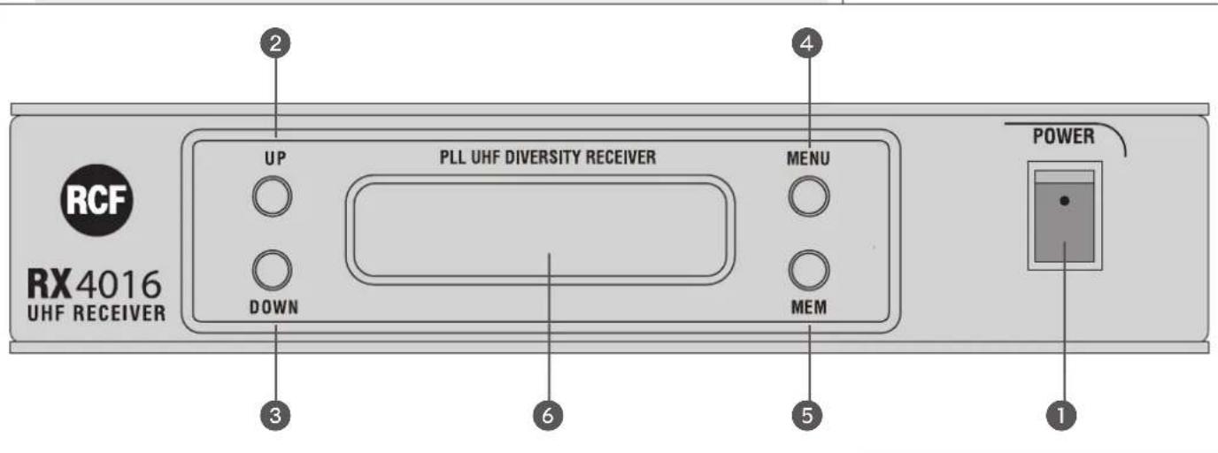
1 POWER switch to turn the RX 4016 receiver on/off.
2 UP key: it increases the value of the selected parameter (chosen through the MENU key 4).
3 DOWN key: it decreases the value of the selected parameter (chosen through the MENU key 4).
4 MENU key: press once or more times to select the parameter to edit.
5 MEM key
- Press once (and immediately release) to store the new settings (when editing).
- Press and hold (1 second) to start the auto-scan.
6 LCD Display
The LCD display shows both radio (RF) and audio (AF) signals, remaining battery life of the transmitter, selected group – channel – frequency. See the 'RX 4016 operation' manual section for detailed information.
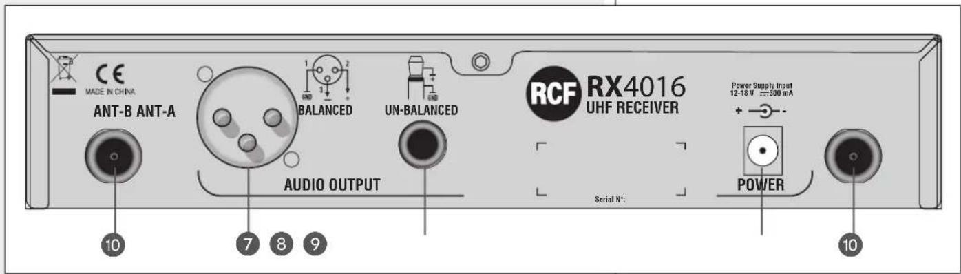
7 BALANCED AUDIO OUTPUT
XLR connector:
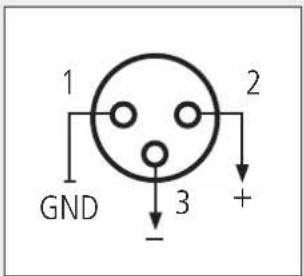
1-ground
2 - audio signal (hot, +)
3 – audio signal (cold, —)
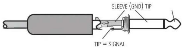
8 UNBALANCED AUDIO OUTPUT
6.3 mm ( 14 ) 'TS' jack connector:
UNBALANCED SIGNAL (TS JACK)
9 POWER SUPPLY INPUT
Connect the output of the included power supply unit (15 V dc) to this input.
10 ANT-A, ANT-B antenna inputs
Inputs for the included antennas (or remote antennas, not included).
DISPLAY
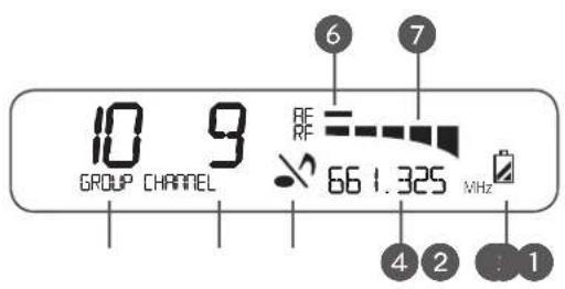
1 Selected frequency group (1 ÷ 10)
2 Selected channel (1 ÷ 12)
3 Mute function
4 Frequency (MHz) corresponding to the selected channel
5 Transmitter remaining battery life
6 AF: bar graph indicating the received audio level
7 RF: bar graph indicating the field strength of the received radio signal
AUTO-SCAN
Press and hold the MEM 5 key for one second to start the auto-scan function, which automatically searches the current transmitter carrier frequency in the entire band. During the search, the display shows the channel sequence and the audio output is muted. As soon as the transmitter frequency is found, the scan will be stopped automatically and the current channel / frequency will be flashing. At this point, press the MEM key to store the new channel.
NOTE: IN SOME CASES, IT MAY BE NECESSARY TO SELECT THE CHANNEL MANUALLY (SEE THE NEXT 'MANUAL CHANNEL SELECTION').
MANUAL CHANNEL SELECTION
Press the MENU ④ key: on display 'GROUP' is now flashing and it is possible to select the group through the UP ② / DOWN ③ keys.
When the group is set, press the MEM 5 key to store the new setting (or the MENU 4 key to cancel).
Then press the MENU 4 key twice (sequentially): on display 'CHANNEL' is now flashing and it is possible to select the channel through the UP 2 / DOWN 3 keys. When the channel is set, press the MEM 5 key to store the new setting (or the MENU 4 key to cancel).
AUDIO OUTPUT LEVEL ADJUSTING (balanced audio output 7 only)
Press the MENU 4 key 3 times (sequentially): the display indicates 'PL' and a value.
Use the UP 2 / DOWN 3 keys to adjust the receiver (max.) audio output level:
- PLO 500 mV
- PL 1 300 mV
- PL 2 150 mV
Press the MEM 5 key to store the new setting (or the MENU 4 key to cancel).
NOTE: THIS PARAMETER ONLY AFFECTS THE BALANCED AUDIO OUTPUT 7.
DISPLAY
AUTO-SCAN

MANUAL CHANNEL SELECTION
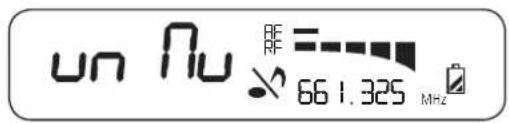
Press the MENU ④ key 4 times (sequentially): the display indicates the mute function (the note in the centre is now flashing).
Use the UP 2 / DOWN 3 keys to turn the mute function on / off and then press the
MEM 5 key to store the new setting (or the MENU 4 key to cancel).
If the mute function is on, the receiver audio output will be disabled.
MUTE FUNCTION
MUTE FUNCTION: OFF MUTE FUNCTION: ON
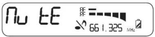
NOTE: IF THE TRANSMITTER IS MUTED, NO AUDIO SIGNAL WILL BE SENT OUT FROM THE RECEIVER!
SqUELCH CONTROL
The squelch can be useful to reduce audible noise during pauses, by muting the receiver every time the radio signal level drops below a defined threshold, which is set through the squelch control.
A higher value means a higher squelch threshold.
Use the squelch control with care: if its threshold is too high, the squelch could also mute the transmitter signal. A too high squelch threshold also decreases the usable range.
Press the MENU 4 key 5 times (sequentially): the display indicates 'Si' and a value.
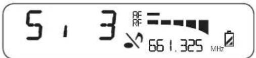
Use the UP 2 / DOWN 3 keys to adjust the receiver squelch threshold:
| VALUE | SQUELCH THRESHOLD LEVEL |
| 1 | -95.0 dB |
| 2 | -91.7 dB |
| 3 | -88.3 dB |
| 4 | -85.0 dB |
| 5 | -81.7 dB |
| 6 | -78.3 dB |
| 7 | -75.0 dB |
| 8 | -71.7 dB |
| 9 | -68.3 dB |
| 10 | -65.0 dB |
Press the MEM 5 key to store the new setting (or the MENU 4 key to cancel).

SqUELCH CONTROL
TX 4000 TRANSMITTER / HANDHELD DYNAMIC MICROPHONE
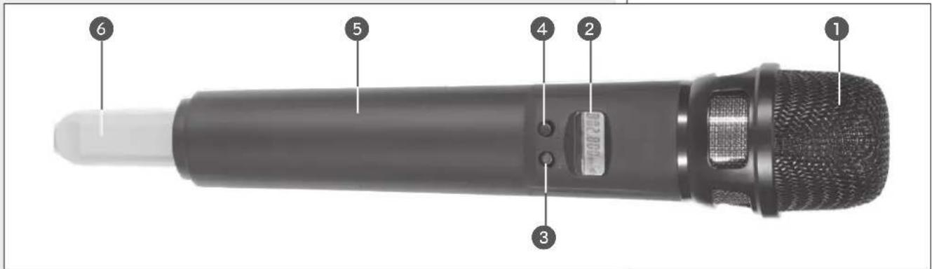
Remove (unscrew) the microphone handle to access the battery compartment 5.
1 MIC. CAPSULE GRILLE
Extremely rugged spring steel mesh grille to protect the capsule underneath in live performances.
2 LCD DISPLAY
See the 'TX 4000 / PX 4100 transmitter operation' manual section for detailed information.
3 CH/ON key
Press and hold (for a few seconds) this key to turn the transmitter on / off. When the transmitter is switched on, press once or more times to select the parameter to edit:
- C H. channel selection
- GP. group selection
- P L. RF power level
- Unlock / Lock
Press once or more time the SELECT key 4 to change values.
After a few seconds since the last setting, the display will show the current selected frequency [MHz] and the battery life.
4 SELECT key
Press once or more time to change values when editing parameters.
Press and hold (for a few seconds) to mute / unmute the microphone.
5 BATTERY COMPARTMENT
Use 2 non-rechargeable 'AA' type (1.5 V) batteries, better if alkaline and new.
Pay attention to the polarity when inserting the 2 batteries.
6 ANTENNA
The antenna is integrated in the transmitter, under the coloured plastic cap (that is available in 7 different colours for easy identification).
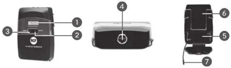
1 LCD DISPLAY
See the 'TX 4000 / PX 4100 transmitter operation' manual section for detailed information.
2 CH/ON key
Press and hold (for a few seconds) this key to turn the transmitter on / off.
When the transmitter is switched on, press once or more times to select the parameter to edit:
- C H. channel selection
- G P. group selection
- P L. RF power level
- Unlock / Lock
Press once or more time the SELECT key 3 to change values.
After a few seconds since the last setting, the display will show the current selected frequency [MHz] and the battery life.
③ SELECT key
Press once or more time to change values when editing parameters.
Press and hold (for a few seconds) to mute / unmute the transmitter.
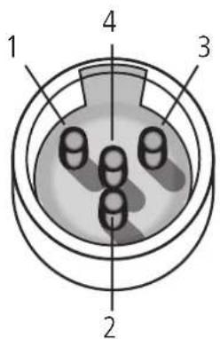
4 INPUT (mini 4P connector)
Input for the LA 2004 'Lavalier' (tie-clip) electret microphone.
PIN
-
ground
-
power supply for electret microphones
-
audio signal input for an electric guitar / bass
(a cable with jack - mini 4p connectors is needed, NOT included in RCF kits)
- audio signal input for a microphone
5 BATTERY COMPARTMENT
Use 2 non-rechargeable 'AA' type (1.5 V) batteries, better if alkaline and new. Pay attention to the polarity when inserting the 2 batteries.
6 BELT CLIP
7 FLEXIBLE ANTENNA
NOTE: AVOID COVERING THE ANTENNA WITH HANDS, CLOTHES, ETC.
PIN

IMPORTANT INFORMATION
- Refer to local regulations for the use of wireless microphones.
- When more wireless devices are used at the same time, each transmitter / receiver pair shall be set to its own channel that must be different from all already used. A channel (frequency) can be used for 1 transmitter only (2 or more transmitters cannot be set to the same channel).
- It is possible to use up to 16 channels simultaneously. For instance, the following 10 channels can be used simultaneously without any interference:
- group 1, channel 1 638.125 MHz
- group 1, channel 2 638.325 MHz
- group 1, channel 5 638.925 MHz
- group 2, channel 2 640.725 MHz
- group 2, channel 10 642.325 MHz
- group 4, channel 3 645.725 MHz
- group 5, channel 2 647.925 MHz
- group 6, channel 8 651.525 MHz
- group 7, channel 1 652.525 MHz
-
group 8, channel 5 655.725 MHz
-
In case of interferences due to lighting equipments, computers, other radio transmitters, etc. nearby, it is advisable to try different frequencies.
- Wireless microphones should be used in an open-space with no obstacles (especially metallic objects) between transmitters and receivers.
- For the best performances, always use 2 new non-rechargeable alkaline 'AA' TYPE batteries and keep transmitters as close as possible to receivers.
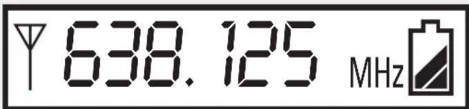
Press and hold (for a few seconds) the CH/ON key 2 to turn the transmitter on. The current selected frequency [MHz] and the battery life are displayed.
OPERATION
When the transmitter is switched on, press once or more times the CH/ON key 2 to select the parameter to edit:
- C H. channel selection
- GP. group selection
- P L. RF power level
- Unlock / Lock (setting protection)
Press once or more time the SELECT key 3 to change values.
THE SELECT KEY 3 CANNOT CHANGE CHANNELS, GROUPS AND RF POWER IF THE 'UNLOCK / LOCK' PARAMETER IS SET TO 'LOCK'.
After a few seconds since the last setting, the display will show the current selected frequency and the battery life again.
CHANNEL SELECTION
The frequency range is in the UHF band (638 ÷ 662 MHz).
Before setting a different channel, please see the table (groups, channels and respective frequencies) in the 'Frequency' manual section.
For instance, to select the frequency preset of 659.125 MHz (group 9, channel 10), please follow the following procedure:
- Turn the transmitter on first.
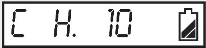
- Press CH/ON key 2 once to edit the channel parameter, then press once or more times the SELECT key 3 to specify the proper channel (example: no. 10).
- Press the CH/ON key ② once again to edit the group parameter, then press once or more times the SELECT key ③ to specify the proper group (example: no. 9).
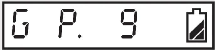
After a few seconds, the last setting will be automatically stored and the display will show the (new) selected frequency and the battery life again.
RF OUTPUT POWER SELECTION
Press CH/ON key 2 3 times to edit the RF output power, then press once or more time the SELECT key 3 to change values.

| SELECTION | TX 4000 / PX 4100 RF OUTPUT POWER |
| PL 0 | 1 mW |
| PL 1 | 3 mW |
| PL 2 | 10 mW |
After a few seconds, the last setting will be automatically stored and the display will show the selected frequency and the battery life again.
LOCK FUNCTION
Since the CH/ON and SELECT keys may be accidentally pressed, it is possible to protect the current settings thanks to the 'lock' function.
When the transmitter is set to 'lock', it is still possible to use the CH/ON key to select parameters, but only the 'Unlock / Lock' can be edited.
Press CH/ON key ② 4 times to edit the 'Unlock / Lock' parameter, then use the SELECT key ③ to select.
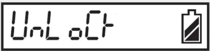

After a few seconds, the last setting will be automatically stored and the display will show the selected frequency and the battery life again.
MUTE
Press and hold (for a few seconds) the SELECT key 3 to mute the transmitter.
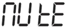

When the transmitter is muted, the audio signal is NOT transmitted (while the carrier radio signal is still present).
Press and hold the SELECT key 3 again to unmute the transmitter.
MUTE
FREQUENCIES

The following table shows all available frequencies [MHz] assigned to every group / channel.
| Channel 1 | Channel 2 | Channel 3 | Channel 4 | Channel 5 | Channel 6 | Channel 7 | Channel 8 | Channel 9 | Channel 10 | Channel 11 | Channel 12 | |
| Gr. 1 | 638.125 6 | 38.325 638 | 525 638.72 | 5 638.925 | 639.125 639 | 325 639.5 | 25 639.725 | 639.925 640 | 0.125 640.3 | 25 | ||
| Gr. 2 | 640.525 6 | 40.725 640 | 925 641.12 | 5 641.325 | 641.525 641 | 725 641.9 | 25 642.125 | 642.325 642 | 2.525 642.7 | 25 | ||
| Gr. 3 | 642.925 6 | 43.125 643 | 325 643.52 | 5 643.725 | 643.925 644 | 125 644.3 | 25 644.525 | 644.725 644 | 4.925 645.1 | 25 | ||
| Gr. 4 | 645.325 6 | 45.525 645 | 725 645.92 | 5 646.125 | 646.325 646 | 525 646.7 | 25 646.925 | 647.125 647 | 7.325 647.5 | 25 | ||
| Gr. 5 | 647.725 6 | 47.925 648 | 125 648.32 | 5 648.525 | 648.725 648 | 925 649.1 | 25 649.325 | 649.525 649 | 9.725 649.9 | 25 | ||
| Gr. 6 | 650.125 6 | 50.325 650 | 525 650.72 | 5 650.925 | 651.125 651 | 325 651.5 | 25 651.725 | 651.925 652 | 2.125 652.3 | 25 | ||
| Gr. 7 | 652.525 6 | 52.725 652 | 925 653.12 | 5 653.325 | 653.525 653 | 725 653.9 | 25 654.125 | 654.325 654 | 4.525 654.7 | 25 | ||
| Gr. 8 | 654.925 6 | 55.125 655 | 325 655.52 | 5 655.725 | 655.925 656 | 125 656.3 | 25 656.525 | 656.725 656 | 6.925 657.1 | 25 | ||
| Gr. 9 | 657.325 6 | 57.525 657 | 725 657.92 | 5 658.125 | 658.325 658 | 525 658.7 | 25 658.925 | 659.125 659 | 9.325 659.5 | 25 | ||
| Gr.10 | 659.725 6 | 59.925 660 | 125 660.32 | 5 660.525 | 660.725 660 | 925 661.1 | 25 661.325 | 661.525 661 | 1.725 661.9 | 25 |
SPECIFICATIONS

SYSTEM
Channel
Type
Frequency band
Frequency response
Frequency stability
T.H.D.
Modulation mode
Dynamic
RX 4016 RECEIVER
Balanced audio output
Unbalanced audio output
S/N Ratio
RF sensitivity
Power supply
Dimensions
Net weight
TX 4000 TRANSMITTER / HANDHELD MICROPHONE
RF output power
Frequency response
Microphone capsule
Tone frequency
Max. deviation
Batteries
Dimensions
Net weight
PX 4100 BODY PACK TRANSMITTER
RF output power
Frequency response
LA 2004 mic. freq. resp.
Tone frequency
Max. deviation
Batteries
Dimensions
Net weight
Included microphone
single (out of 120 frequencies)
(PLL) UHF, 'diversity' receiver
UHF, 638 ÷ 662 MHz
50 Hz ÷ 50 kHz (± 3 dB)
± 0.005 % (-10 ÷ 50°C)
< 0.8% (1 kHz)
FM (F3E)
100 dB
1 V, ± 35 kHz deviation
750 mV, ± 35 kHz deviation
90 dB
- 100 dBm / 30 dB SINAD
through external 15 V dc (0.5A) adapter
2 x 'AA' type (1.5 V, non rechargeable)
277 mm (l), ∅ 36.5 mm;
(10.9" x ∅ 1.44")
0.25 kg
1 - 3 - 10 mW
50 Hz ÷ 15 kHz (± 3 dB)
100 Hz ÷ 12 kHz (± 3 dB)
30-33 kHz
± 35 kHz
2 x 'AA' type (1.5 V, non rechargeable)
LA 2004 'Lavalier' (tie-clip) electret
microphone
AVVERTENZE PER LA SICUREZZA

IMPORTANTE
II kit TX 4016 include:
II kit PX 4116 include:
FUNZIONAMENTO
(PLL) UHF, "diversity"
UHF, 638 ÷ 662 MHz
50 Hz ÷ 50 kHz (± 3 dB)
± 0,005 % (-10 ÷ 50°C)
< 0,8% (1 kHz)
FM (F3E)
100 dB
Risp. Freq. Mic. LA 2004
Except possible errors and omissions.
RCF S.p.A. reserves the right to make modifications without prior notice.
- OWNER MANUAL MANUALE D'USO
- TX 4016 PX 4116
- INDEX INDICE
- ENGLISH
- ITALIANO
- SAFETY PRECAUTIONS
- IMPORTANT NOTES
- WARNING
- NOTES ABOUT BATTERIES
- DESCRIPTION
- FEATURES
- COMMON
- RX 4016 RECEIVER RACK MOUNTING
- RX 4016 FRONT PANEL
- BALANCED AUDIO OUTPUT
- UNBALANCED AUDIO OUTPUT
- POWER SUPPLY INPUT
- ANT-A, ANT-B antenna inputs
- DISPLAY
- AUTO-SCAN
- MANUAL CHANNEL SELECTION
- AUDIO OUTPUT LEVEL ADJUSTING (balanced audio output 7 only)
- MUTE FUNCTION
- SqUELCH CONTROL
- TX 4000 TRANSMITTER / HANDHELD DYNAMIC MICROPHONE
- MIC. CAPSULE GRILLE
- LCD DISPLAY
- CH/ON key
- SELECT key
- BATTERY COMPARTMENT
- ANTENNA
- LCD DISPLAY
- CH/ON key
- ③ SELECT key
- INPUT (mini 4P connector)
- PIN
- BELT CLIP
- FLEXIBLE ANTENNA
- IMPORTANT INFORMATION
- - Refer to local regulations for the use of wireless microphones.
- OPERATION
- CHANNEL SELECTION
- RF OUTPUT POWER SELECTION
- LOCK FUNCTION
- MUTE
- FREQUENCIES
- SPECIFICATIONS
- SYSTEM
- Channel
- RX 4016 RECEIVER
- TX 4000 TRANSMITTER / HANDHELD MICROPHONE
- RF output power
- PX 4100 BODY PACK TRANSMITTER
- AVVERTENZE PER LA SICUREZZA
- IMPORTANTE
- FUNZIONAMENTO
Brand : RCF
Model : PX 4116
Category : Telephone