
Force10 S25-01-GE-24P - Network switch DELL - Free user manual and instructions
Find the device manual for free Force10 S25-01-GE-24P DELL in PDF.


| Product Type | Network switch |
| Brand | Dell |
| Model | Force10 S25-01-GE-24P |
| Form Factor | 1U rackmount |
| Ports | 24 x 10/100/1000Base-T (PoE+) |
| Uplink Ports | 4 x 1/10 Gigabit SFP+ |
| Switching Capacity | 56 Gbps |
| Forwarding Rate | 41.66 Mpps |
| PoE Budget | 370 W |
| MAC Address Table Size | 16,000 entries |
| VLAN Support | Yes (up to 4096) |
| Management | CLI, SNMP, web GUI, SSH |
| Power Supply | AC 100-240 V, 50-60 Hz |
| Power Consumption | 450 W max |
| Dimensions (H x W x D) | 1.72 x 17.1 x 15.2 in |
| Weight | 14.6 lb |
| Operating Temperature | 32°F to 113°F (0°C to 45°C) |
| Humidity | 10% to 90% non-condensing |
| Cooling | Internal fans (front-to-back airflow) |
| Safety Compliance | UL, CE, FCC Class A, VCCI |
| Mounting | Rackmount kit included |
| Cleaning Instructions | Wipe with a dry, soft cloth; do not use liquids or solvents |
| Maintenance | Check fans and air filters; ensure ventilation |
| Spare Parts Availability | Power supply modules, fan trays (hot-swappable) |
Frequently Asked Questions - Force10 S25-01-GE-24P DELL
User questions about Force10 S25-01-GE-24P DELL
0 question about this device. Answer the ones you know or ask your own.
Ask a new question about this device
Download the instructions for your Network switch in PDF format for free! Find your manual Force10 S25-01-GE-24P - DELL and take your electronic device back in hand. On this page are published all the documents necessary for the use of your device. Force10 S25-01-GE-24P by DELL.
USER MANUAL Force10 S25-01-GE-24P DELL
Installing S25N and S25V Systems
December 15, 2008 100-00061-02

natural_image
Close-up of server rack with multiple drive bays and a hexagonal mesh grille (no visible text or symbols)Copyright 2008 Force10 Networks®
All rights reserved. Printed in the USA. December 2008.
Force10 Networks® reserves the right to change, modify, revise this publication without notice.
Trademarks
Force10 Networks® and E-Series® are registered trademarks of Force10 Networks, Inc. Force10, the Force10 logo, E1200, E600, E600i, E300, EtherScale, TeraScale, and FTOS are trademarks of Force10 Networks, Inc. All other brand and product names are registered trademarks or trademarks of their respective holders.
Statement of Conditions
In the interest of improving internal design, operational function, and/or reliability, Force10 Networks reserves the right to make changes to products described in this document without notice. Force10 Networks does not assume any liability that may occur due to the use or application of the product(s) described herein.

Note: The country-specific warnings and statements of compliance have been moved to "Agency Compliance" on page 42, in Chapter 6, "System Specifications," on page 41.
Feedback on Documentation? Send email to techpubs@force10networks.com
Contents
Preface
About this Guide 5
Information Symbols and Warnings 5
Related Publications 7
Chapter 1
System Overview 9
Equipment 10
Features 11
Ports 11
System Status 12
LED Displays 12
Chapter 2
Site Preparation 15
Site Selection 15
Cabinet Placement 16
Rack Mounting 16
Fans and Airflow 16
Power 17
S25N 17
S25V 17
Power over Ethernet (PoE) Support 17
Storing Components 18
Tools Required 18
Chapter 3
Installing the Switch 19
Inserting Optional Modules (10-Gigabit or Stacking) 19
Installing the System on a Tabletop 21
Installing the System in a Rack or Cabinet 21
Two-Post Rack Mounting 21
Four-Post Rack-mounting with Threaded Rails 22
Four-Post Rack-mounting with Cage Nuts 23
Stacking 26
Using FTOS Stacking Commands 26
Connecting Stack Ports (optional) 27
Supplying Power 29
S25V 29
Chapter 4
Installing Backup Power 31
Backup Power Components 31
The Power Connections on the Switch 32
Installing the Redundant DC Power Supply for the S25V 33
Inserting Tandem PSUs into a Rack 34
Connecting the DC-to-DC Cable 34
Chapter 5
Installing Ports 37
Accessing the Console Port 37
Connecting S25V Ethernet Ports with PoE 38
Installing Optics 39
Installing SFPs 39
Installing XFPs 40
Chapter 6
System Specifications.... 41
Physical Design 41
Environmental Parameters 41
Power Requirements 42
Agency Compliance 42
Safety Standards and Compliance Agency Certifications 44
Electromagnetic Compatibility (EMC) 44
Product Recycling and Disposal 45
Appendix A
Technical Support 47
The iSupport Website 47
Accessing iSupport Services 48
Contacting the Technical Assistance Center 49
Locating Serial Numbers 49
Requesting a Hardware Replacement 50
Index 51
Preface About this Guide
This guide provides site preparation recommendations, step-by-step procedures for rack mounting and desk mounting, inserting optional modules, and connecting to a power source.
After you have completed the hardware installation and power-up of the system, refer to the FTOS Configuration Guide for the S-Series for software configuration information and the FTOS Command Reference for the S-Series for detailed Command Line Interface (CLI) information, as detailed in Related Publications, below.
Information Symbols and Warnings
The following graphic symbols are used in this document to bring attention to hazards that exist when handling the system and its components. Please read these alerts and heed their warnings and cautions.
Table 1 describes symbols contained in this guide.
Table 1 Information Symbols
| Symbol | Warning Description | |
 | Danger | This symbol warns that improper handling and installation could result in bodily injury.Before you begin work on this equipment, be aware of hazards involving electrical circuitry, networking environments, and instigate accident prevention procedures. |
 | Caution | This symbol informs you that improper handling and installation could result in equipment damage or loss of data. |
 | Warning | This symbol informs you that improper handling may reduce your component or system performance. |
 | Note This | symbol informs you of important operational information. |

Danger: The installation of this equipment shall be performed by trained and qualified personnel only. Read this guide before installing and powering up this equipment. This equipment contains two power cords. Disconnect both power cords before servicing.

Danger: Class 1 laser product.
This equipment contains optical transceivers, which comply with the limits of Class 1 laser radiation. Visible and invisible laser radiation may be emitted from the aperture of the optical transceiver ports when no cable is connected. Avoid exposure to laser radiation and do not stare into open apertures.

Warning: Building Supply Notice for AC Power Supply Use
This product relies on the building's installation for short-circuit (overcurrent) protection. Ensure that a fuse or circuit breaker no larger than 120 VAC, 15A U.S. (240 VAC, 10A international) is used on the phase conductors (all current-carrying conductors).
Warning: Building Supply Notice for DC Power Supply Use
An external disconnect must be provided and be easily accessible. Force10 Networks recommends the use of a 60A circuit breaker.
Caution: Wear grounding wrist straps when handling this equipment to avoid ESD damage.

Caution: Earthing (AKA grounding) connection essential before connecting supply. Always make the ground connection first and disconnect it last.

Caution: Disposal of this equipment should be handled according to all national laws and regulations. See Product Recycling and Disposal on page 45.

Caution: This unit has more than one power supply connection; all connections must be removed to remove all power from the unit.
Caution: Lithium Battery Notice
Danger of explosion if battery is replaced with incorrect type. Replace only with the same type recommended by the manufacturer. Dispose of used batteries according to the manufacturer's instructions.
Note: Other cautionary statements appear in context elsewhere in this book.
Related Publications
The S25N and S25V run FTOS version 7.7.1.0 or greater. Refer to the following documents:
• FTOS Configuration Guide for the S-Series
• FTOS Command Reference for the S-Series
• S-Series and FTOS Release Notes
The FTOS Documentation CD-ROM contains the S-Series hardware guides and the FTOS files listed above. The CD-ROM also has:
- MIBs: Files for all SNMP MIBs supported by the software
- Data sheets: Links to Force10 product data sheets
• Security: Description and supporting files for setting up SSH, SSL, and HTTPS access to the switch - Training: PDF files of the slide shows used in training

Note: Documentation CD-ROMs do not have software or Release Notes. For the most recent documentation and software, please visit iSupport (registration for access to some sections is required):
https://www.force10networks.com/CSPortal20/Main/SupportMain.aspx
The iSupport website also has a section for S-Series techtips and FAQs. For more information in this book on technical support, see Technical Support on page 39.
Chapter 1 System Overview
The S25N (Cat# S25-01-GE-24T) and S25V (Cat# S25-01-GE-24V) models of the S-Series are high performance, low cost, stackable, Layer 2 switch/Layer 3 routers that support 24 built-in 10/100/1000 Base-T ports with four shared 1GbE SFP (small form-factor pluggable) ports, and two rear expansion slots that can host stacking ports or up to four 10GbE ports. The two differences between the two models are:
- The on S25N Super Ethernet (PoE) through its 24 copper ports (see Connecting S25V Ethernet Ports with PoE on page 38), while the S25N does not.
- The tS25V(470W) and DC power inputs, while the S25N has two AC inputs (150W+150W). See Supplying Power on page 29. The S25V can also use the Force10 470W Redundant DC Power Supply (see Chapter 4, Installing Backup Power, on page 31) in current sharing (additive) mode.
Figure 1 shows the front panel of the S25V. The S25N has almost the same layout, except that the catalog name differs, and an AC2 status LED replaces the DC status LED.
Figure 1 The S25V Front View

Figure 2 The S25V Rear View

Figure 3 The S25N Rear View

Equipment
The following items are necessary to install the system:
- The switch
- At least one grounded AC power source for the S25N switch (ideally two for the two AC receptacles), and one for the S25V. The S25V provides the option of using DC power with, or in addition to, AC.
- Cable (included) to connect the AC power source to the switch
- Brackets ("rack ears") for rack installation (included)
- Screws for rack installation (included) and #2 Phillips screwdriver (not supplied)
Other optional components are:
- Stacking cables for connecting switches when stacked (not supplied). See Connecting Stack Ports (optional) on page 27.
• Backup DC Power Module (see Chapter 4, Installing Backup Power, on page 31) - Rear rack-mounting kits (see Installing the System in a Rack or Cabinet on page 21)
• Optical networking components (see Chapter 5, Installing Ports, on page 37) - Stacking components (see Ports, below)
Features
- Dual power supplies:
— S25N: Two 150W AC power supplies (two receptacles; see Figure 3 on page 10) acting in load-sharing mode.
— S25V: Internal AC (110v/220v auto-detect) and DC (-48V) power supplies (see Figure 2 on page 10) each capable of 470W, and acting in load-sharing mode. The S25V has built-in support for 360W Power over Ethernet (PoE) — IEEE 802.3af — through the copper ports, with power allocation controll available through the CLI. The optional Force10 470W DC Redundant Power Supply can be attached in current-sharing mode to provide up to 940W (790W of PoE).
- Supports up to 16384 MAC address entries supported with hardware-assisted aging
- Stackable switch features
- 19-inch rack-mountable and standard 1U chassis height
- F a n s :
— S25N: Four fans with automatic speed adjustment for temperature changes
— S25V: Five fans with automatic speed adjustment for temperature changes
• Supports 9252-byte jumbo frames
- Back-pressure support at half-duplex, IEEE 802.3x flow control at full duplex
- Extensive LED system with per-port LEDs
• 32MB internal Flash memory
• 2 5 6 M B R A M
Ports
- 24 fixed 10/100/1000 Mbps auto-sensing and auto-MDIX RJ45 ports (The S25V provides up to 15.4W PoE to each port.)
- Four SFP ports that share port numbers 21–24 with the copper ports and capable of using 10/100/1000 Base-T or 1000 Base-X using auto-media detect
- Console port (see Chapter 5, Installing Ports, on page 37): Supplied with console cable (straight-through Ethernet copper cable) and terminal adapter (DB-9 to RJ-45)
- Expansion slots that accept any combination of the following optional, high-capacity uplink modules: 10GbE XFP (two ports), 10GbE CX4 (two ports), 12G stacking (two ports) or 24G stacking (one port). See Inserting Optional Modules (10-Gigabit or Stacking) on page 19 and Connecting Stack Ports (optional) on page 27.
System Status
Chassis status can be derived in several ways, including physical LED displays and boot menu options, along with CLI show commands and SNMP traps. For details on boot menu and CLI options, see:
- The CLI Basics and BOOT_USER chapters in the FT OS Command Reference for the S-Series
- The Configuration Fundamentals and Getting S-tarted chapters in the FTOS Configuration Guide for the S-Series
LED Displays
As shown in Figure 1 on page 9, the front panel of the switch contains several sets of LEDs:
- The LED group labeled “STACK ID” at the far left of the front panel displays the stack ID of the unit. See Stack ID in Table 3. For more on unit numbering, see Stacking on page 26.
• Each port has status indicator LEDs, described in Table 2. - A group of status indicator LEDs are on the left side of the front panel, described in Table 3.
Table 2 Port LED Displays
| Feature Description | |
| 10/100/1000 Port LED* | Speed LED (left side of each port)Green — 1000MAmber — 100MOff — 10MLink/Active LED (right side of each port)Green — Link up on this portBlinking Green — Activity, transmitting or receiving packet at this port.Amber — Link up and power supplied on this portBlinking Amber – Transmitting or receiving packets on the port and sending PoE power to PD (power device)Off — No Link detected at this port |
| SFP Port LED* | Link LEDGreen — Link up on this portOff — No link detected on this portActivity LEDBlinking Green — Activity, transmitting or receiving packet in link up stateOff — No activity on this port |
| XFP Port LED | Link/Activity LED (Each XFP port has a status LED on the module and in the LED group at the left front of the switch)Green — Link up on this portBlinking Green — Activity, transmitting or receiving packet in link up stateOff — No link detected on this port |
* The SFP ports have priority over the four shared 10/100/1000 ports (ports 21–24). LEDs for a 10/100/1000 port are inactive if the shared SFP port (also labeled 21 through 24) is enabled.
Table 3 describes the LED status indicators on the left side of the front panel.
Table 3 Status Panel LED Display
| Label LED Color Description | ||
| Left Side of the Status LED Group | ||
| OK | Green | Unit is online. |
| Off | Unit is powered off. | |
| Green Blinking | Unit is booting up. (blinking rate is 16 Hz) | |
| Amber | Error during boot-up. | |
| AC1 (on S25N) | Green | Power supply is present and OK. |
| AC (on S25V) | Amber | Power supply is present but failed. |
| Off | Power supply is not present. | |
| XFP25* | Green | A valid 10G link is established on the port. |
| Blinking Green | Transmitting or receiving packets on the port. | |
| Off | No link is established on the port. | |
| XFP26* | Green | A valid 10G link is established on the port. |
| Blinking Green | Transmitting or receiving packets on the port. | |
| Off | No link is established on the port. | |
| STACK ID Green | Indicates the stack ID (sometimes called "switch ID") of the unit.Starting with FTOS 7.8.1.0:“A” is displayed to the left of the stack ID if the unit is a standalone or master (management) unit.“B” is displayed for a standby unit. (Actually, it’s an 8, because of the limitations of the 7-segment LED.)“0” is displayed next to the stack ID, as before, for the other units. | |
| Right Side of the Status LED Group | ||
| Alarm | Amber | Minor alarm: Fan or temperature is operating outside parameters. |
| Red | Major alarm | |
| Off | No alarm | |
| AC2 (on S25N) | Green | Power supply is present and OK. |
| DC (on S25V) | Amber | Power supply is present but failed. |
| Off | Power supply is not present. | |
| XFP27* | Green | A valid 10G link is established on the port. |
| Blinking Green | Transmitting or receiving packets on the port. | |
| Off | No link is established on the port. | |
| XFP28* | Green | A valid 10G link is established on the port. |
| Blinking Green | Transmitting or receiving packets on the port. | |
| Off | No link is established on the port. | |
* Each of the four XFP LEDs on the front panel also indicate the status when CX4 ports are installed in the rear bays.
Chapter 2 Site Preparation
This chapter describes requirements and procedures to install your S25N or S25V system, in the following topics:
- Site Selection
• Cabinet Placement on page 16 - Rack Mounting on page 16
• Fans and Airflow on page 16
• Power on page 17
• Storing Components on page 18 - Tools Required on page 18
For detailed system specifications, refer to Chapter 6, System Specifications, on page 41.

Note: Install the system into a rack or cabinet before installing any optional components.
Site Selection
Make sure that the area where you install the system meets the following safety requirements:
- Near an adequate power source. Connect the system to the appropriate branch circuit protection as defined by your local electrical codes.
- Ambient temperature between 32irc - 122ircF (0irc - 50ircC) .
- Relative humidity that does not exceed 85% non-condensing.
- In a dry, clean, well-ventilated, and temperature-controlled room, away from heat sources such as hot air vents or direct sunlight.
- Away from sources of severe electromagnetic noise.
- Positioned in a rack, cabinet, or on a desktop with adequate space in the front, rear, and sides of the unit for proper ventilation, and access.
Cabinet Placement
The cabinet must meet the following criteria:
- Minimum cabinet size and airflow are according to the EIA standard.
• Minimum of 5 inches (12.7 cm) between the side intake and exhaust vents and the cabinet wall.
Rack Mounting
When you prepare your equipment rack, ensure that the rack is earth ground. The equipment rack must be grounded to the same ground point used by the power service in your area. The ground path must be permanent.
Fans and Airflow
Ventilation is side-to-side, with five fans (four fans in the S25N) on the left side of the switch that operate at a constant speed. For proper ventilation, position the system in an equipment rack (or cabinet) with a minimum of five inches (12.7 cm) of clearance around the side intake and exhaust vents. When two S-Series systems are installed side by side, position the two systems at least 5 inches (12.7 cm) apart to permit proper airflow. The acceptable ambient temperature ranges are listed in Environmental Parameters on page 41.
As listed in Table 3, “Status Panel LED Display,” on page 13, the front panel of the system has an Alarm status LED, which is green when the switch is operating within required temperature parameters and all components are operating normally, including fans. The LED is amber when the temperature or components are outside expected parameters, red in a major alarm.
FTOS turns on major and minor alarms and logs temperature warnings at the following temperatures (in degrees Celsius), and logs another message when the temperature returns to normal. The Command Line Interface (CLI) also reports an alarm. The fan speed changes accordingly.
Table 4 Major and Minor Temperature (Degrees Celsius) Warnings
| S25N S25V | ||
| Major On 62 60 | ||
| Major Off 58 56 | ||
| Minor On 60 58 | ||
| Minor Off 50 47 |
Use the show logging command to see the log messages. For details, see the logging chapters of the Command Reference and Configuration Guide. In a stack, each unit has its own temperature monitoring and control. Status logging is identified by unit in the system log.
Fan replacement in the field is not offered as an option.
Power
S25N
The S25N comes standard with two 150W AC power supplies with auto-sensing 110/220V AC receptacles, each of which, when connected to a power source, is capable of supplying all required power to the switch. When both are connected to power sources, they act in load-sharing mode; see Figure 3 on page 10. Use the power cords shipped with the S25N to connect it to AC power outlets, ideally on separate circuits. Several versions of the power cord are available, based on country requirements.

Caution: The power supply cord is used as the main disconnect device; ensure that the socket-outlet is located/installed near the equipment and is easily accessible.
S25V
As shown in Figure 2 on page 10, the right side (as you face the back of the unit) of the S25V contains one auto-sensing 110/220V AC receptacle and a -48V DC terminal block.
When both the AC and DC power supplies are connected on the S25V, it uses them in load-sharing mode. If the 470W DC Backup Power Supply provided by Force10 is connected to the Current Sharing connection on the back of the S25V, the system uses the DC and AC in current-sharing mode, which is load-sharing up to 470W, while also allowing them to provide a total of 940W. The 470W PSU is oversized in order to support PoE, as described next. See also Backup Power Components on page 31.
For details on connecting to a power source, see Supplying Power on page 29.
Power over Ethernet (PoE) Support
Along with the optional DC power supply noted above, the S25V includes an internal 470W power supply that supports both the operation of the switch and an independent power distribution system to supply power to the 24 copper Ethernet ports that support the IEEE 802.3af standard for Power over Ethernet (PoE). Connect only powered devices that adhere to IEEE 802.3af.
The total PoE power budget for the switch is between 320W and 790W, depending on the power sources available. If the external 470W DC Force10 Redundant Power Supply (catalog # S50-01-PSU-V) is attached to the Current Sharing terminal (see Chapter 4, Installing Backup Power, on page 31), you can use the power-budget command in FTOS to convert its use to current-sharing mode to provide up to 790W of PoE.
Each port can provide a maximum of 15.4W, subject to the power budget, voltage, power priority, and power limit settings. PoE is, by default, enabled globally on a first-come, first-serve basis, until it exceeds the total available power. Alternatively, the switch administrator can use the CLI to allocate power on a per-port and a per-stack-unit basis, with per-port power limits and port prioritization. For a brief introduction in this guide to the PoE commands, see Connecting S25V Ethernet Ports with PoE on page 38.
Storing Components
If you do not install your system and components immediately, Force10 Networks recommends that you properly store the system and all optional components until you are ready to install them. Follow these storage guidelines:
• Storage temperature should remain constant, in the range from -40irc to 158irc F ( -40irc C to 70irc C).
- Storage humidity should be within 10 to 90% (relative humidity), non-condensing
- Store on a dry surface or floor, away from direct sunlight, heat, and air conditioning ducts.
- Store in a dust-free environment.
Tools Required
S-Series switches are shipped fully assembled, encased in foam. A utility knife is useful for cutting the packing tape, and a Philips #2 screwdriver is required for attaching rack screws, and is also used for making some attachments, including DC cables and rear cover plates.

Warning: Electrostatic discharge (ESD) damage can occur when components are mishandled. Always wear an ESD-preventive wrist or heel ground strap when handling the system and its accessories. After you remove the original packaging, place the system and its components on an antistatic surface.
Chapter 3 Installing the Switch
To install S25N or S25V systems, Force10 Networks recommends that you complete the installation procedures in the order presented in this chapter:
- Inserting Optional Modules (10-Gigabit or Stacking)
• Installing the System on a Tabletop on page 21 - Installing the System in a Rack or Cabinet on page 21
- Stacking on page 26
— Using FTOS Stacking Commands on page 26
— Connecting Stack Ports (optional) on page 27
• Supplying Power on page 29

Warning: As with all electrical devices of this type, take all the necessary safety precautions to prevent injury when installing this system. Electrostatic discharge (ESD) damage can occur if components are mishandled. Always wear an ESD-preventive wrist or heel ground strap when handling the switch and its components.
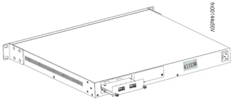
Inserting Optional Modules (10-Gigabit or Stacking)
The S25N (catalog name S25-01-GE-24T) and S25V (catalog name S25-01-GE-24V) have two expansion slots in the rear of the units, for which there are four modules available:
| Module Description Catalog Name | |
| 2-port 10GbE XFP (optical connection) S50-01-10GE-2P | |
| 2-port 10GbE CX4 (copper connection) S50-01-10GE-2C | |
| 2-port 12GbE Stacking S50-01-12G-2S | |
| 1-port 24GbE Stacking S50-01-24G-1S | |
The system supports the modules inserted in any combination of slots (although connecting all four ports of two 12G stacking modules is not supported, nor is connecting a 12G stack port in one switch to a 24G stack port in another switch). The ports are numbered 25 through 28, from left to right as you face the front of the unit. So, for clarity in the use of the CLI in port assignment, if you are only using one XFP or CX4 module, insert it in the left-most expansion slot.
Note: The 10G modules cannot be used for stacking. See Connecting Stack Ports (optional) on page 27.
Step Task
| 1 | If the system is on, save the running configuration, if desired (and different from the startup configuration) with the command write memory. Then power down the system by unplugging it from its power source.Caution:Hotswapping (inserting or removing) a module can crash and lock up the system, requiring a power cycle. |
| 2 | Use a #2 Phillips screwdriver to remove either a module faceplate or an existing module. Note that these slots, when used for 10G Ethernet ports, are assigned port numbers from left to right as you face the front of the system. So, for clarity in programming those ports, you might favor the left-most slot for the first 10G module that you install. |
| 3 | Grasping the module faceplate, remove the module from its packaging and slide it into the slot until the module faceplate is flush with the rear cover of the system. |
natural_image
Line drawing of a server rack unit with ventilation slots and ports (no text or symbols)4 Secure the captive screws on either side of the module.
| 5 XFP: Using the optical XFP 10-Gigabit module (catalog name S50-01-10GE-2P) requires additional XFP transceiver inserts, which are not included in the module kit (see Installing XFPs on page 46 or the installation instructions that come with the transceiver). The CX4 module (catalog name S50-01-10GE-2C) ports do not require inserts. |
CX4: Using a CX4 module requires using CX4 cables that are approved for the target device. Cables are not part of the module kit, but they are orderable from Force10. For details, see Using CX4 Cables (CX4 Cable Matrix) in the S-Series tech tips on iSupport:
https://www.force10networks.com/CSPortal20/KnowledgeBase/ToolTipsSSeries.aspx
When using cables substantially shorter or longer than 5 meters, use the cx4-cable-length command to set the signal strength. Use cx4-cable-length long for a longer cable, cx4-cable-length short for a shorter cable. For details, see the Interfaces chapter in the FTOS Command Reference.
You can connect a CX4 cable to an XFP port through a CX4 XFP converter (catalog name GP-XFP-1CX4) in the slot. However, an XFP port does not support the use of the cx4-cable-length command, discussed next.
Do not connect CX4 ports to 12G stack ports in the switch. The receptacles and cables are the same, but they are incompatible. CX4 ports are labeled as such; stack ports are not labeled.
For details on enabling ports, see the FTOS Configuration Guide.
Installing the System on a Tabletop
The system can be positioned on a stable tabletop. Four rubber standoffs are provided for that purpose in the plastic bag in the switch shipping box. Keep the following in mind when using a tabletop:
- Ensure that your tabletop is stable and can handle the weight of the switch or a stack of switches, if that is the case, along with any added backup power supplies.
- Position the table for proper ventilation and easy access to separate power outlets for each device.
Installing the System in a Rack or Cabinet
The system provides three rack-mounting methods:
- Two-Post Rack Mounting
• Four-Post Rack-mounting with Threaded Rails on page 22
• Four-Post Rack-mounting with Cage Nuts on page 23
Two-Post Rack Mounting
The system is shipped with the universal front-mounting brackets (rack ears) attached. Ensure that there is adequate clearance surrounding the rack to permit access and airflow. If you are installing two switches side-by-side, position the two unit at least 5 inches (12.7 cm) apart to permit proper airflow.
Position the unit in the rack. Secure the unit with two of the supplied screws through each bracket and onto the rack post.
Figure 4 Two-post (Front-mounted) Rack-mounting

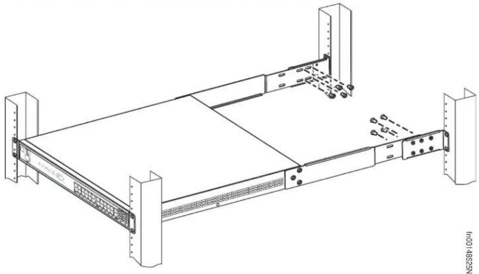
Four-Post Rack-mounting with Threaded Rails
Ensure that there is adequate clearance surrounding the cabinet or rack to permit access and airflow. If you are installing two S-Series units side-by-side, position the two units at least 5 inches (12.7 cm) apart to permit proper airflow. Follow the steps below to install a unit into a 4-post 19-inch equipment rack, using the attached front mounting brackets and the optional adjustable rear-mounting brackets.
Step Task
1
Align the three screw holes of the adjustable rear mounting bracket with the three holes in the unit, and secure the mounting bracket with three screws.
Figure 5 Four-Post Rack-mounting with Threaded Rails

natural_image
Technical line drawing of a server rack with mounting hardware (no text or symbols)2
Insert the unit into the rack, and secure the unit to the front post with two screws. Then secure it to the rear posts with two screws.
Figure 6 Four-Post Rack-mounting with Threaded Rails

Step Task
3 Set the adjustable rear mounting bracket to the length (one of three lengths) for your bracket. Secure the length with the four screws.
Figure 7 Four-post Rack-mounting with Threaded Rails
natural_image
Technical line drawing of a server rack with mounting brackets and mounting holes (no text or symbols)Four-Post Rack-mounting with Cage Nuts
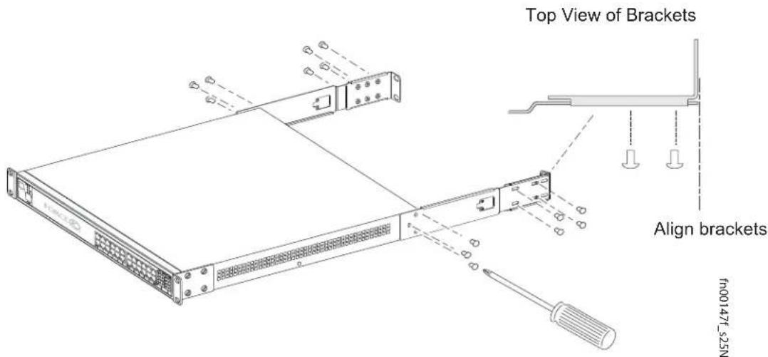
Ensure that there is adequate clearance surrounding the cabinet or rack to permit access and airflow. If you are installing two S-Series units side-by-side, position them at least 5 inches (12.7 cm) apart. Follow the steps below to install the unit into a four-post rack mounting with cage nuts.
Step Task
1
Attach the two rear brackets to the side panels. Align the three holes in the bracket with the three holes on the unit, and secure the brackets to the unit using the screws.
Figure 8 Four-Post Rack-mounting with Cage Nuts
2
Align and secure the adjustable bracket onto the rear bracket.
3
Insert the unit into the rear of the rack. Position and secure the unit with two screws into each front bracket flange and into the rack post.
Figure 9 Four-Post Rack-mounting with Cage Nuts

natural_image
Line drawing of a server rack unit with mounting flanges and ventilation grilles (no text or symbols)Step Task
4 Position the cage nuts over the holes on each bracket flange and each rack post.
Figure 10 Four-Post Rack-mounting with Cage Nuts

5 Align the rack filler panel to the rear bracket and rack posts. Secure by inserting two screws into the hole in the filler panel through to the holes in the rack post.
Figure 11 Four-Post Rack-mounting with Cage Nuts

natural_image
Technical line drawing of a server rack with mounting brackets and a screwdriver (no text or symbols)Stacking
You can add units to a stack, remove them, renumber them, or move them in the stack. The units can continue running in the stack as you add new units, but new units should be powered down during the connection.
All units in a stack must run the same version of FTOS. If you attempt to attach a unit with a different FTOS version to an existing stack, the CLI will display an error, and the unit will not be added until you install identical software.
The order in which the units come on-line or are added to or removed from the stack can affect how the stack identifies them, and how the units identify themselves, influencing unit numbers, stack management assignment, and other elements of the configuration file.
How units are identified within the stack is determined by the identification algorithm. The algorithm has the units self-identify as Unit 1 through Unit [last] based on the order in which they come online. So, when setting up a new stack, you should have no trouble forcing the identification of the management unit and unit IDs by methodically supplying power to the units in your preferred sequence.
Similarly, when you add a brand new unit to the stack, the unit will be gracefully added as Unit [last] (the lowest unused number) with the current configuration.
If you have a pre-configured unit to add to the stack, but you want to make sure that the configuration does not override the configuration of the stack, it is best to add the unit while it is powered down, in order to avoid stack management conflicts.
Using FTOS Stacking Commands
While the S-Series hardware has built-in stacking controls, you can use FTOS to manage stacking, such as assign unit IDs, influence the management unit (master unit) selection algorithm, pre-configure a unit to be added to a stack, etc. The following commands provide a sample of that functionality:
- Use the stack-unit unit priority 1-14 command to configure the ability of an S-Series switch to become the management unit of a stack.
- Use the stack-unit unit provision {S25N|S25P|S25V|S50N|S50V} command to pre-configure a stacking ID of a switch that will join the stack. This is an optional command that is executed on the management unit.
- Use the stack-unit unit renumber unit command to renumber a standalone S-Series or any stack member.
• Use the show system brief command to see the current assignment of the management unit. - Use the show system stack-unit unit command to see the serial number of the designated unit and other system details.
• Use the show system stack-ports command to see the stacking topology and status.
For details on using FTOS to remove a unit from a stack or use other stacking commands, see the Stacking Commands chapter in the FTOS Command Reference and the S-Series Stacking chapter in the FTOS Configuration Guide.
Connecting Stack Ports (optional)
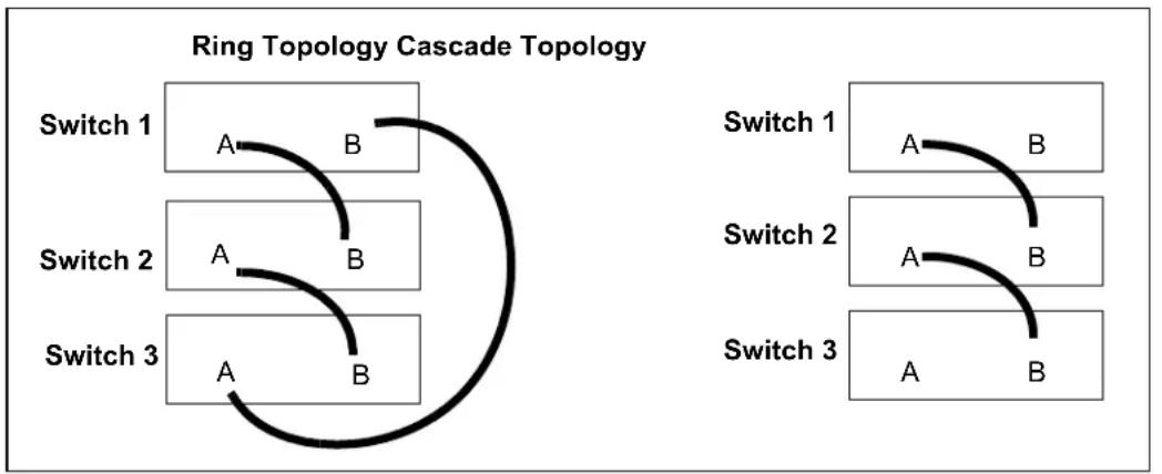
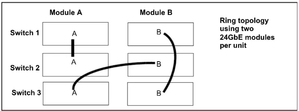
The switch contains two expansion slots in the rear, in either of which you can insert stacking modules for converting the switch into a virtual slot in a single virtual switch, called a stack (they all must be running the same software version). The switch provides two optional choices in stacking modules — a single-port 24G module and a two-port 12G module. You cannot interconnect the two types of module. If you use 24G modules, you can insert one in each of the two expansion slots to accomplish the ring topology (Figure 13).
You can connect the switches while they are powered down or up. You can use either a ring topology or cascade topology connection (see Figure 12). Use the special stacking cables to connect them. Force10 recommends that you mount the switches before you make your stack port connections.
Figure 12 Switch Stacking Topologies (showing dual-port modules)
flowchart
graph TD
    subgraph Ring Topology Cascade Topology
        Switch1["Switch 1"] -->|A| B1["B"]
        Switch1 -->|B| B2["B"]
        Switch2["Switch 2"] -->|A| B3["B"]
        Switch2 -->|B| B4["B"]
        Switch3["Switch 3"] -->|A| B5["B"]
        Switch3 -->|B| B6["B"]
    end
While the diagram, above, shows A-B port connections, the ports are bi-directional, so you can connect A to A and/or B to B, as shown below in examples of two-switch (Figure 14 on page 28) and three-switch (Figure 15 on page 28) ring topologies.
Figure 13 shows the use of 24G stack ports in each of the two rear modules to create a ring. Of course, this topology does not allow the use of any rear modules for XFP ports. A cascade topology, removing the stack port modules in the B slots of switches 1 and 2, would free those slots for use by XFP modules.
Figure 13 Stacking Topology Using 24G Single-port Modules
flowchart
graph TD
    A["Switch 1"] -->|A| B["Module A"]
    C["Switch 2"] -->|A| D["Module A"]
    E["Switch 3"] -->|A| F["Module A"]
    G["Module B"] -->|B| H["Module B"]
    style A fill:#f9f,stroke:#333
    style C fill:#f9f,stroke:#333
    style E fill:#f9f,stroke:#333
    style G fill:#f9f,stroke:#333
    note right of G Ring topology using two 24GbE modules per unit
Connecting Two Switches
Insert one end of the special stacking cable into a stack port, and insert the other end into a stack port of the adjacent switch. Optionally, insert a second cable into the other open stack port, as shown in Figure 14. The second cable provides both backup connectivity and increased data transfer between the units.
Figure 14 Stack Ports of Two S25V Switches Connected in a Ring


Note: Figure 14 and Figure 15 and these instructions use “Stack Port A” and “Stack Port B” for clarifying the connections, but the modules are not labeled.
Connecting Three Switches
Force10 recommends the ring topology, as outlined above (Figure 12 on page 27), because that provides redundant connectivity. Using the example of three switches in the stack (Figure 15), and starting with the switch at the bottom of the stack:
1 Insert one end of the first cable into Stack Port A.
2. Insert the other end of the cable into S tack Port A of the middle switch.
3. Insert the second cable into Stack Port B of the middle and top switches.
- Connect the remaining cable to the top and bottom switches by inserting one end of the cable into the open Stack Port B of the bottom switch and the other end of the cable into Stack Port A of the top switch.
Figure 15 S25V Rear View Showing Ring Topology Stacking

Supplying Power
Supply power to the units in a stack only after they are mounted and the stack ports are connected. There is no on/off switch, and the stack members partly determine the stack management unit from the order in which they come on-line (see below).

Danger: To prevent electrical shock, make sure the switch is grounded properly. If you do not ground your equipment correctly, excessive emissions can result. Use a qualified electrician to ensure that the power cables meet your local electrical requirements. See other relevant cautions in Information Symbols and Warnings on page 7.
S25N
The S25N has two AC receptacles in the rear of the unit (see Figure 3 on page 10). The system can use either power source independently, or act in load-sharing mode.
Connect the supplied AC power cord first to either receptacle (on the right as you face the rear of the system) and then to the power source (see AC Power Requirements on page 50). Ensure that the cord is secure. If you connect both AC power supplies, ideally you would connect them to separate circuits.
S25V
The S25V has both an AC (3-prong plug receptacle) and a DC (-48V terminal-type) connection on the back of the unit (see Figure 2 on page 10). Each power source can be used independently or in load-sharing combination. In other words, you have three options for providing power to the switch — AC only, DC only, or using both AC and DC sources.
In addition, Force10 provides, as an option, an external 470W DC Redundant Power Supply Unit (PSU), which can be connected in either load-sharing mode or current-sharing mode. For details, see Chapter 4, Installing Backup Power, on page 31.
To use AC only, connect the supplied AC power cord first to the switch (receptacle on the right as you face the rear of the unit) and then to the power source (see AC Power Requirements on page 50). Connect the plug to the AC receptacle at the right rear of the switch, making sure that the power cord is secure.
For DC power, you must provide your own cables to connect to the power source. Cables must be sized for 11.5 A service at no more than -48 VDC input (per NEC in the United States; internationally; follow local safety codes.). Before you make the cable connections, apply a coat of antioxidant paste to unplated metal contact surfaces. File unplated connectors, braided straps, and bus bars to a shiny finish.
1 Make sure that the remote power source (the circuit breaker panel) is in the OFF position.
2. Remove the safety cover from the DC terminal block.
3. Connect the grounding cable to the FG terminal first, then connect the opposite end to the appropriate grounding point at your site to ensure an adequate unit ground.
4. Connect the -48 V and -48 V RTN (Return) cables to the switch terminals and then to the remote power sources. For the Current Sharing terminal, see Chapter 4, Installing Backup Power, on page 31.
5. Replace the safety covers on the DC terminal block.
Chapter 4 Installing Backup Power
This chapter covers the following topics:
- Backup Power Components
• The Power Connections on the Switch on page 32
• Installing the Redundant DC Power Supply for the S25V on page 33 - Inserting Tandem PSUs into a Rack on page 34
- Connecting the DC-to-DC Cable on page 34
The S25N has two AC connections, with no external backup option. You can connect either one or both. When both are connected, they operate in load-sharing mode.
The S25V has both AC and DC power connections. You can connect either one or both. When both are connected, they operate in load-sharing mode, but the AC input is slightly preferred over the DC (60/40). If you connect the 470W DC Force10 Redundant Power Supply Unit (PSU) to the Current Sharing lug on the switch, the power supplies operates in current-sharing mode, which means they operate both in load-sharing mode and in additive mode, yielding a total of 940W (790W for PoE).


Danger: To prevent electrical shock, make sure the switch is grounded properly. If you do not ground your equipment correctly, excessive emissions can result. Use a qualified electrician to ensure that the power cables meet your local electrical requirements.
See other relevant cautions in Information Symbols and Warnings on page 5.
Backup Power Components
The optional Redundant Power Supply Unit (PSU) for the S25V supplies 470W DC, supporting both the switch itself and the PoE feature. The PSU kit includes:
• The AC/DC rectifier (catalog name S50-01-PSU-V)
- DC-to-DC cable to connect the PSU to the switch
- AC cable to connect the PSU to the AC power source
- PSU mounting hardware: extended rac k ears, twinning plate, screws, cage nuts, and four rubber feet that you can attach to the PSU if you want to set it on a table
The Power Connections on the Switch
The S25N contains two AC connections, while the S25V contains one AC and one DC. An AC cable is supplied with the switch for each connection (see Supplying Power on page 29). On both systems, you can connect one or both of the inputs to power.
On the S25V, if both AC and DC connections are made and able to supply power, the switch will only utilize them in load-sharing mode. If you attach the Force10 470W DC Redundant PSU, and you want to supply maximum PoE power, you connect the blue DC Current Sharing lead so that the internal and external DC power supplies can work in current-sharing mode, allowing the power supplies to work in load-sharing mode up to 470W and then in additive mode up to 940W (790W maximum for PoE).
The DC input to the switch uses industry-standard terminal leads on a terminal block. The S25V has four connections — ground (FG), -48 volt input, return (RTN), and Current Sharing, as shown in Figure 16:
Figure 16 DC Terminals on the S25V

[NO TEXT]
Installing the Redundant DC Power Supply for the S25V
The Redundant Power Supply Unit (PSU) for the S25V is a 470W AC/DC rectifier. It includes rack-mounting hardware, an AC cable, and a cable to connect to the DC power leads on the S25V. The power supply is oversized to support the Power over Internet (PoE) feature, too large to install in the S50 External Power Shelf (EPS). Instead, to install the PSU in a rack, complete the steps below for a single unit. For a tandem installation, see Inserting Tandem PSUs into a Rack on page 34.
Step Task
- Using a #2 Phillips screwdriver, attach the short sides of the rack ears to the front corners of the power supply with the supplied screws.
Figure 17 Attaching Rack Ears to PSU

natural_image
Illustration of a server rack with a screwdriver inserted, showing internal components and cable routing (no text or symbols)-
Insert the PSU into the rack and brace it temporarily in the rack so that the screw holes in the long sides of the rack ears are flush and align with the screw holes in the rack posts.
-
Secure the PSU on the left and right sides by tightening the supplied screws through the flanges to the side of the rack, as shown in Figure 18. (Cage nuts are also supplied for racks that have mounting holes without threads.)
Figure 18 Mounting Single PSU in Rack

natural_image
Diagram of a server rack with attached cable and connectors (no text or symbols)Inserting Tandem PSUs into a Rack
To install two PSUs in tandem (side-by-side) in a rack, follow these steps:
Step Task
-
Using a #2 Phillips screwdriver, attach the supplied extended rack ears to the outside, front sides of the two PSUs. As shown in Figure 20, the long side of the rack ear is attached to the PSU, with the short side projecting at right angles away from the front corner of the PSU.
-
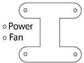
Join the two units with the supplied twinning plate (the small, flat, I-beam-shaped metal adapter with four screw holes), using two screws on each side of the plate through the front inside corners of the two switches. Orient the adapter with the cross-bars of the I-beam horizontally, so that the fan and power LEDs in the left-hand PSU are not obscured.
Figure 19 Twinning Plate Oriented over Two PSUs
- As shown on the left side of Figure 20, attach the rack ears to the rack with the supplied screws or cage nuts, depending on the style of your rack.
Figure 20 Two PSUs Mounted Side-by-Side

natural_image
Technical diagram of a server rack with screwdrivers and mounting hardware (no text or symbols)Connecting the DC-to-DC Cable
The PSU kit includes two power cables — the cable that connects the PSU to the AC source and the DC-DC cable that connects the PSU to the terminal block on the back of the S25V. The DC-DC cable length is 1 meter (3 feet), with a keyed plug connector at one end that connects to the PSU, and, at the other end, individual wires that connect to the DC terminal leads in the rear of the S25V.
Figure 21 DC-DC Cable for S25V PSU

natural_image
Coiled black electrical plug with three terminal leads, no visible text or symbolsFollow the steps below to connect the S25V switch to the 470W PSU.
Step Task
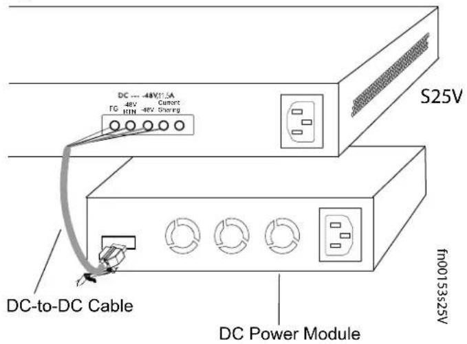
- With the switch unplugged from AC power, connect the individual leads of the DC-to-DC cable to the DC terminal lugs of the switch (Figure 22), with a #2 Philips screwdriver. Connect the gray wire to FG (field ground), red to RTN (return), brown to -48V, and blue to Current Sharing:
Figure 22 DC Terminals of the S25V Connected to the PSU Cable

- Insert the plastic plug of the DC-to-DC cable into the receptacle on the lower left side of the PSU (Figure 23).
Note that one of the three leads on the plug has a trapezoidal key ☐, which goes in the receptacle that is toward the center of the PSU. The key is not strong enough to resist being inserted in the opposite receptacle, and it is difficult to see, so you must take care to insert it correctly. To help you orient it, note that the top side of the plug has a knurled pattern.
Figure 23 DC-to-DC Connection
-
Tighten the captive screws on the sides of the connector cable by turning them clockwise.
-
Insert the supplied AC-to-AC cable into the AC receptacle of the PSU. Ideally, you should connect that cable to an AC source separate from the AC connection made directly to the S25V.

Caution: Use only the power cords supplied with the power supply. Do not supply power to the system until the power supply and modules have been installed.
Chapter 5 Installing Ports
This chapter contains these major sections:
- Accessing the Console Port on page 37
- Connecting S25V Ethernet Ports with PoE on page 38
• Installing Optics on page 39
Accessing the Console Port
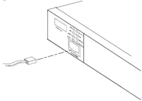
Connect the RJ-45/DB-9 adapter that is shipped with the system to the RJ-45 cable.
Console port pinout:
Pin 1 = NC
Pin 2 = NC
Pin 3 = RXD
Pin 4 = GND
Pin 5 = GND
Pin 6 = TXD
Pin 7 = NC
Pin 8 = NC
Figure 24 Console Port of S25V
natural_image
Line drawing of a device with a cable and connected via a cable to a terminal block (no text or symbols)Set your initial console terminal settings to match the default console settings on the switch:
- 9600 baud rate
• No parity - 8 data bits
- 1 stop bit
- No flow control (console port only)
After establishing a connection, you can modify the settings to match at each end of the connection.
To access the console port, use the follow procedure:
Step Task
1

Install the RJ-45 copper cable that is shipped with the system into the console port.
Caution: You must install a straight-through RJ-45 copper cable (a standard Ethernet cable) into the console port. This is different from many other implementations that require an Ethernet crossover cable (or rollover cable). If connecting to a terminal server and using a crossover cable, daisychain another crossover cable to effectively get a straight-through cable connection. Many console terminal servers use octopus cables that are crossover cables. To accommodate the octopus cable, connect an additional crossover cable, as above, to effectively install a straight-through cable.
2
If necessary, connect the RJ-45/DB-9 adapter that is shipped with the system to the end of the RJ-45 cable that will connect to your terminal.
3 Verify that your terminal's settings match the default settings on the console port, as listed above. FTOS does not have the ability to enable you to set a higher speed on the console port.
To make other console port configuration changes, such as setting the console port timeout or setting up access security, use the line console command in CONFIGURATION mode of the CLI.
Connecting S25V Ethernet Ports with PoE
The copper ports (ports 1 through 24) in the S25V are able to deliver power to connected powered devices that follow the IEEE 802.3af specification for Power over Ethernet (PoE). For delivering PoE, use the same Cat. 5 cables and RJ-45 connectors that you use for non-PoE connections. The PoE pinout is shown in Figure 25.
Figure 25 RJ-45 PoE pinout
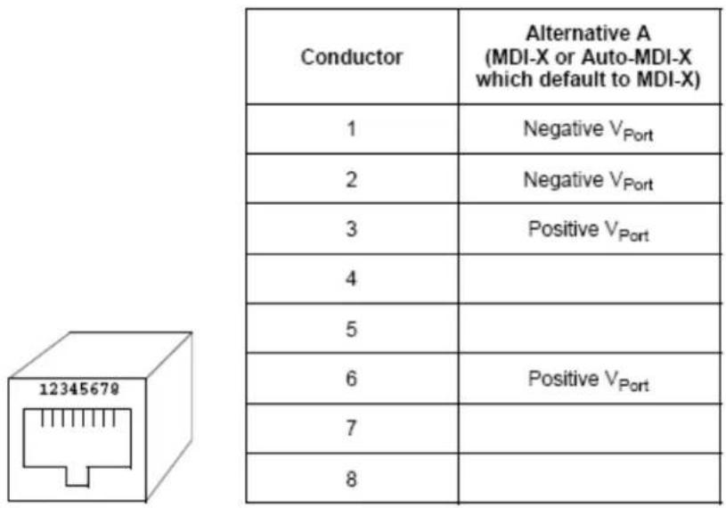
The internal AC 470 watt power supply will limit PoE power to 320 watts if the switch requires power for other uses, and the default PoE configuration limits PoE power to 288 watts. As described in Power over Ethernet (PoE) Support on page 17, you can raise that limit with an external power supply running in load-sharing mode and with certain FTOS commands.
So, while each port can provide more than the maximum of 15.4 watts required by the IEEE 802.3af specification, the available power to a particular port is subject to the power budget of the switch and to the power already allotted to other ports. You can use the CLI to prioritize the allocation of power per port and to raise the power budget threshold. For more on CLI commands that control PoE, see the PoE chapters of the FTOS Configuration Guide for the S-Series and the FTOS Command Reference for the S-Series.
Installing Optics
The S25N and S25V each have four receptacles at the right end of their faceplates that accommodate 10/100/1000 SFP optical transceivers.
On the back of the switches, there are two bays that accept either stacking modules or 10GbE modules (CX4 or XFP). A 10GbE module contains two ports. 10GbE modules should only be inserted or removed when the switch is powered down, as detailed in Inserting Optional Modules (10-Gigabit or Stacking) on page 19 in Chapter 3, Installing the Switch.
SFP and XFP transceivers can be inserted or removed while the switch is running.

Caution: Before connecting a transceiver to a source, check the receive power of the transceiver with an optical power meter. Generally, Force10 specified optics are not to be subjected to receive power higher than that stipulated by the optic specification. If the optic is exposed to optical power in excess of the specification, there is a high likelihood that it will be damaged.
Optical specifications for Force10 branded devices are at the following URL: http://www.force10networks.com/products/mediaspecifications.asp
Force10 Networks offers various types of SFP and XFP transceivers. For details, see: http://www.force10networks.com/products/specifications.asp
Installing SFPs
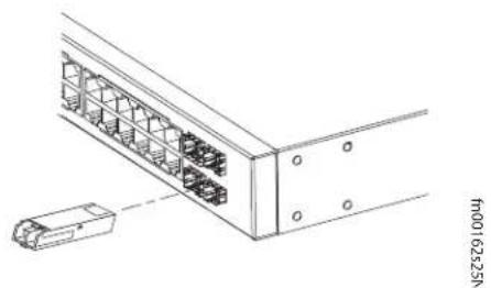
To install an SFP into one of the four ports at the right front of the switch, follow the steps below:

Warning: Electrostatic discharge (ESD) damage can occur if components are mishandled. Always wear an ESD-preventive wrist or heel ground strap when handling the system and its components.
Step Task
1 Position the SFP so it is in the upright position. (The SFP has a key that prevents it from being inserted incorrectly.)
2 Insert the SFP into the port until it gently snaps into place.
natural_image
Technical line drawing of a server rack with multiple connectors and a separate connector (no text or symbols)Figure 26 Front View of S25N with SFP
Installing XFPs
To install an XFP into one of the two ports in the optional 10GbE module (see Inserting Optional Modules (10-Gigabit or Stacking) on page 19) on the back of the switch, follow the procedure below:

Warning: Electrostatic discharge (ESD) damage can occur if components are mishandled. Always wear an ESD-preventive wrist or heel ground strap when handling the system and its components.
Warning: Do not look directly into any optical port. Failure to follow this warning could result in physical harm. For details, see Information Symbols and Warnings on page 5.
Step Task
1 Position the XFP so it is in the upright position. (The XFP has a key that prevents it from being inserted incorrectly.)
2 Insert the XFP into the port until it gently snaps into place.
Figure 27 Rear View of S25N with XFP

natural_image
Diagram of a device with two wheels and a connected box, no text or symbols presentfn00160s50V

Note: The CX4 module does not use transceivers. However, you can use a CX4 cable with an XFP port by inserting a CX4 XFP converter (catalog name GP-XFP-1CX4) into the slot. An XFP port does not support the use of the cx4-cable-length command. For details, see Inserting Optional Modules (10-Gigabit or Stacking) on page 19 in Chapter 3, Installing the Switch.
For enabling ports with FTOS, see the FTOS Configuration Guide for the S-Series.
Chapter 6
System Specifications
Physical Design
| Parameter Specifications | |
| Weight (with only factory-installed components) 19.5 pounds (approx.) (8.85 kg) | |
| Height 1.73 inches (4.4 cm) | |
| Width 17.32 inches (44 cm) (19" rack-mountable) | |
| Depth 16.73 inches (42.5 cm) (standard 1 rack unit – 1RU) | |
| Rack clearance required Front: 5-inches (12.7 cm) | |
| Rear: 5-inches (12.7 cm) | |
Environmental Parameters
| Parameter Specifications | |
| Temperature 32° to 122°F (0° to 50°C) | -40° to 158°F (-40° to 70°C) non-operating (storage temperature) |
| Maximum Thermal Output S25N: 349.05 BTU/Hour | S25V: 349.05 BTU/Hour |
| Maximum altitude No performance degradation to 10,000 feet (3,048 meters) | |
| Relative humidity 10 to 85% non-condensing (operating) | 5 to 95% non-condensing (storage) |
| Shock designed to meet MIL-STD-810 | |
| Vibration | Telcordia GR-63-CORE |
| ISO 7779 A-weighted sound pressure level | S25N: 42.0 dBA at 73.4°F (23°C) |
| S25V: 42.9 dBA at 73.4°F (23°C) | |
Power Requirements
| Parameter Specifications | |
| Nominal input voltage 90 – 254 VAC, 47/63 Hz | |
| Maximum current draw S25N: 2 A @ 100/120 VAC; 1 A @ 200/240 VACS25V (AC): 6.5 A @ 100/120 VAC; 3.25A @ 200/240 VACS25V (DC): 11.5A @ -48 VDC | |
| Minimum AC current draw .35 A @ 254 VAC.62 A @ 90 VAC | |
| Maximum power consumption S25N, S25V: 102WS25N (AC): 156WS25N (DC): 136W | |
| Maximum PoE power 320W for PoE using either AC or DC inputs790W for PoE using load-sharing AC and DC inputs |

Note: The S25N and S25V contain no user-serviceable parts. They contain a lithium clock battery that is not field-serviceable. For details on recycling the system or any of its components, see Product Recycling and Disposal on page 45.
Agency Compliance
The S25N and S25V are designed to comply with the following safety and agency requirements.
USA Federal Communications Commission (FCC) Statement
This equipment has been tested and found to comply with the limits for a Class A digital device, pursuant to Part 15 of the FCC rules. These limits are designated to provide reasonable protection against harmful interference when the equipment is operated in a commercial environment. This equipment generates, uses, and can radiate radio frequency energy. If it is not installed and used in accordance to the instructions, it may cause harmful interference to radio communications. Operation of this equipment in a residential area is likely to cause harmful interference, in which case users will be required to take whatever measures necessary to correct the interference at their own expense.
Properly shielded and grounded cables and connectors must be used in order to meet FCC emission limits. Force10 Networks is not responsible for any radio or television interference caused by using other than recommended cables and connectors or by unauthorized changes or modifications in the equipment. Unauthorized changes or modification could void the user's authority to operate the equipment.
This device complies with Part 15 of the FCC Rules. Operation is subject to the following two conditions: (1) this device may not cause harmful interference, and (2) this device must accept any interference received, including interference that may cause undesired operation.
Canadian Department of Communication Statement
Industry Canada Class A emission compliance statement
This Class A digital apparatus complies with Canadian ICES-003.
European Union EMC Directive Conformance Statement
This product is in conformity with the protection requirements of EU Council Directive 2004/108/EC on the approximation of the laws of the Member States relating to electromagnetic compatibility. Force 10 Networks can not accept responsibility for any failure to satisfy the protection requirements resulting from a non-recommended modification of this product, including the fitting of non-Force10 option cards. This product has been tested and found to comply with the limits for Class A Information Technology Equipment according to CISPR 22/European Standard EN 55022. The limits for Class A equipment were derived for commercial and industrial environments to provide reasonable protection against interference with licensed communication equipment.

Attention: This is a Class A product. In a domestic environment, this device may cause radio interference, in which case, the user may be required to take adequate measures.
European Community Contact
Force10 Networks, EMEA - Central
Dahlienweg 19
66265 Heusweiler
Germany
http://www.force10networks.com/german/
Tel: +49 172 6802630
Email: EMEA Central Sales
Japan: VCCI Compliance for Class A Equipment
This is Class A product based on the standard of the Voluntary Control Council For Interference by Information Technology Equipment (VCCI). If this equipment is used in a domestic environment, radio disturbance may arise. When such trouble occurs, the user may be required to take corrective actions.

Danger: AC Power cords are for use with Force10 Networks equipment only. Do not use Force10 Networks AC power cords with any unauthorized hardware.
Korea (MIC certification)
Korean Class A Warning Statement
Safety Standards and Compliance Agency Certifications
• CUS UL (60950-1, 1st Edition)
• CSA 60950-1-03, 1st Edition
• IEC60950-1 1st Ed including all National Deviations and Group Differences
• EN 60950-1, 1st Edition
• EN 60825-1, 1st Edition
- EN 60825-1 Safety of Laser Products—Part 1: Equipment Classification Requirements and User's Guide
• EN 60825-2 Safety of Laser Products—Part 2: Safety of Optical Fibre Communication Systems
• FDA Regulation 21CFR 1040.10 and 1040.11
Electromagnetic Compatibility (EMC)
Emissions
• Australia/New Zealand: AS/NZS CISPR 22: 2006, Class A
• Canada: ICES-003, Issue-4, Class A
• Europe: EN55022 2006 (CISPR 22: 2006), Class A
• Japan: VCCI V3/ 2007.04 Class A
• USA: FCC CFR47 Part 15, Subpart B, Class A
Immunity
• EN 300 386 v1.3.3: 2005 EMC for Network Equipment
• EN 55024 1998 + A1: 2001 + A2: 2003
• EN 61000-3-2 Harmonic Current Emissions
• EN 61000-3-3 Voltage Fluctuations and Flicker
• EN 61000-4-2 ESD
• EN 61000-4-3 Radiated Immunity
• EN 61000-4-4 EFT
• EN 61000-4-5 Surge
• EN 61000-4-6 Low Frequency Conducted Immunity
Product Recycling and Disposal
The switch must be recycled or discarded according to applicable local and national regulations. Force10 Networks encourages owners of information technology (IT) equipment to responsibly recycle their equipment when it is no longer needed. Force10 offers a variety of product return programs and services in several countries to assist equipment owners in recycling their IT products.
Waste Electrical and Electronic Equipment (WEEE) Directive for Recovery, Recycle and Reuse of IT and Telecommunications Products
Force10 switches are labeled in accordance with European Directive 2002/96/EC concerning waste electrical and electronic equipment (WEEE). The Directive determines the framework for the return and recycling of used appliances as applicable throughout the European Union. This label, as shown below, is applied to various products to indicate that the product is not to be thrown away, but rather reclaimed upon end of life per this Directive.
Figure 28 The European WEEE symbol

In accordance with the European WEEE Directive, electrical and electronic equipment (EEE) is to be collected separately and to be reused, recycled, or recovered at end of life. Users of EEE with the WEEE marking per Annex IV of the WEEE Directive, as shown above, must not dispose of end of life EEE as unsorted municipal waste, but use the collection framework available to customers for the return, recycling and recovery of WEEE. Customer participation is important to minimize any potential effects of EEE on the environment and human health due to the potential presence of hazardous substances in EEE.
Force10 Networks products, which fall within the scope of the WEEE, are labeled with the crossed-out wheelie-bin symbol, as shown above, as required by WEEE.
For information on Force10 product recycling offerings, see the WEEE Recycling instructions on iSupport at: https://www.force10networks.com/CSPortal20/Support/WEEEandRecycling.pdf. For more information, contact the Force10 Technical Assistance Center (TAC) (see Contacting the Technical Assistance Center on page 49).
Notice to Recyclers
To open the case:
1 Remove the small phillips screws that connect the top to the body. There should be three evenly spaced across the rear and three evenly spaced along each side.
2 Slide the top backwards until its front flange slides free of the faceplate, then lift it off.
To remove the lithium closed-cell clock battery (clearly visible towards the right rear of switch):
1 Insert a small, flat screw driver blade under the battery and in one of the slots of the plastic retainer underneath the battery.
2 Lever the battery up against the coin cell clip (the hold-down lead on top of the battery) far enough to provide room for the battery to be lifted above the edge of its retainer, as shown in this photograph.

natural_image
Close-up of a hand using tweezers to adjust a small electronic component on a green circuit board (no visible text or symbols)Batteries or packaging for batteries are labeled in accordance with European Directive 2006/66/EC concerning batteries and accumulators and waste batteries and accumulators. The Directive determines the framework for the return and recycling of used batteries and accumulators as applicable throughout the European Union. This label is applied to various batteries to indicate that the battery is not to be thrown away, but rather reclaimed upon end of life per this Directive.
In accordance with the European Directive 2006/66/EC, batteries and accumulators are labeled to indicate that they are to be collected separately and recycled at end of life. The label on the battery may also include a chemical symbol for the metal concerned in the battery (Pb for lead, Hg for mercury and Cd for cadmium). Users of batteries and accumulators must not dispose of batteries and accumulators as unsorted municipal waste, but use the collection framework available to customers for the return, recycling and treatment of batteries and accumulators.
Customer participation is important to minimize any potential effects of batteries and accumulators on the environment and human health due to the potential presence of hazardous substances. For proper collection and treatment, contact your local Force10 Networks representative.
Figure 29 The European WEEE symbol

For California:
Perchlorate Material — Special handling may apply.
See: http://www.dtsc.ca.gov/hazardouswaste/perchlorate
The foregoing notice is provided in accordance with California Code of Regulations Title 22, Division 4.5
Chapter 33. Best Management Practices for Perchlorate Materials.
Appendix A Technical Support
This appendix contains these major sections:
• The iSupport Website
- Contacting the Technical Assistance Center on page 49
- Locating Serial Numbers on page 49
- Requesting a Hardware Replacement on page 50
The iSupport Website
iSupport provides a range of documents and tools to assist you with effectively using Force10 equipment and mitigating the impact of network outages. Through iSupport you can obtain technical information regarding Force10 products, access to software upgrades and patches, and open and manage your Technical Assistance Center (TAC) cases. Force10 iSupport provides integrated, secure access to these services.
The i-Support website (see Figure 30, below) (http://www.force10networks.com/support/) contains a publicly available interface that includes access to techtips, white papers, and user manuals. After you get an account and log in, the available documentation expands to other types, including bug lists, error message decoder, release notes. You can even track your own Force10 inventory.
Once you are logged in, the following five tabs become available:
• Home: Summary of open cases, RMA management, and field notices
• Service Request: Case management
- Software Center: Software downloads, bug fixes, and bug tracking tool
- Documents: User documentation, FAQs, field notices, technical tips, and white papers
• Support Programs: Information on the suite of Force10 support and professional support services.
Figure 30 Support Policies section of iSupport

search force


| Support Overview |
| Contact Support |
| Professional Services |
| Support Policies |
| Customer Login |
| Account Request |
| Documentation |
| E-Series Tech Tips and FAQ |
| S-Series Tech Tips and FAQ |
| S-Series Downloads |
Support Policies
Force10 world class support
Force10 Networks provide world class technical support with modular hardware and sof services to maintain a high performance network. Force10 support policies are streamlin quickly assist customers receive solutions to their technical issues.
Support Guide
Force10 Support guide provides process guidelines for requesting services from Ford Common questions regarding technical support requests, RMA's, training and i-Support u covered.
Support Guide
Support Agreement
The StarSupport end-user agreement covers Force10 support obligations, process for requiring technical and hardware support, support limitations, terminations and definitions.
Force10 Master Support Agreement
Product Warranty
• Force10 Warranty and End User License Agreement
The screenshot above shows the Support Policies section of iSupport. The Support Guide, available on that page, details the types of information and services that you can access through iSupport and through various types of support contracts.
Accessing iSupport Services
The URL for iSupport is http://www.force10networks.com/support/. To access iSupport services you must have a userid and password. If you do not have one, you can request one at the website:
- On the Force10 Networks iSupport page, click the Account Request link.
- Fill out the User Account Request form, and click Send. You will receive your userid and password by E-Mail.
- To access iSupport services, click the LOGIN link, and enter your userid and password.
Contacting the Technical Assistance Center
| How to Contact Force10 TAC | Log in to iSupport at http://www.force10networks.com/support/, and select the Service Request tab. |
| Information to Submit When Opening a Support Case | ·Your name, company name, phone number, and E-mail address·Preferred method of contact·Model number·Serial Number (see Locating Serial Numbers on page 49)·Software version number·Symptom description·Screen shots illustrating the symptom, including any error messages. These can include:·Output from the show tech-support [non-paged] command (This report is very long, so the storage buffer in your terminal program should be set high.)·Output from the show logging eventlog [unit] command, where unit is the stack ID of the member unit that experienced the failure (This report is included as a section in the output of show tech-support.)·Console captures showing the error messages·Console captures showing the trouble shooting steps taken·Saved messages to a syslog server, if one is used |
| Managing Your Case | Log in to iSupport, and select the Service Request tab to view all open cases and RMAs. |
| Downloading Software Updates | Log in to iSupport, and select the Software Center tab. |
| Technical Documentation | Log in to iSupport, and select the Documents tab. This page can be accessed without logging in via the Documentation link on the iSupport page. |
| Contact Information | E-mail: support@force10networks.comWeb: http://www.force10networks.com/support/Telephone:US and Canada: 866.965.5800International: 408.965.5800 |
Locating Serial Numbers
The serial number of the switch is located on a sticker on the back of the unit in the middle. The serial number is below the bar code and has 11 numbers (integers).
Figure 31 Serial Numbers on Back of Chassis

The serial numbers of the optional data modules (10G Ethernet and Stacking) are located on labels on their faces. You can also use the command line interface (CLI) to display serial numbers. In FTOS, use the show inventory unit command to access the serial number of the designated switch (unit = stack ID). For serial numbers of the SFP optics, use the show hardware or show running-config commands. In FTOS, use the show inventory [media] command. You can also use show system for the switch serial number.
Requesting a Hardware Replacement
Step Task
| 1 | Determine the part number and serial number of the component. To list the numbers for all components installed in the chassis, use the commands described above. |
| 2 | Request a Return Materials Authorization (RMA) number from TAC by opening a support case. Open a support case by:Using the Create Service Request form on the iSupport page (see Contacting the Technical Assistance Center, above).Contacting Force10 directly by E-mail or by phone (see Contacting the Technical Assistance Center, above). Provide the following information when using E-mail or phone:Part number, description, and serial number of the component.Your name, organization name, telephone number, fax number, and e-mail address.Shipping address for the replacement component, including a contact name, phone number, and e-mail address.A description of the failure, including log messages. This generally includes:Output from the show tech-support [non-paged] command (This report is very long, so the storage buffer in your terminal program should be set high.)Output from the show logging command. (This report is included as a section in the output of show tech-support.)Console captures showing the error messagesConsole captures showing the troubleshooting steps takenSaved messages to a syslog server, if one is used |
Index
Numerics
10G module serial number 50
10-Gigabit module 10
10-Gigabit module, inserting 19
24G stack ports 27
A
AC Power Supply 6
AC/DC rectifier 33
acoustic noise 41
AC-to-AC cable 36
add units to a stack 26
Agency Compliance 42
Alarm status LED 16
alarms, major and minor 16
altitude, maximum 41
B
back-pressure support 11
backup DC Power Module 10
backup power 33
battery removal 46
battery, lithium 42
baud rate 37
brackets 10
C
Cabinet placement 16
cable, AC-to-AC 36
Canadian compliance 43
catalog name 9
catalog name GP-XFP-1CX4 (for CX4 XFP) 20,40
catalog name S50-01-10GE-2C (CX4 module) 20
catalog name SA-01-PSU-V (external rectifier) 31
Chassis Physical Design
depth 41
height 41
width 41
commands
cx4-cable-length 20
power-budget 17
show logging eventlog 50
show system brief 26
show system stack-ports 26
show system stack-unit 26
show tech-support 50
stack-unit priority 26
stack-unit provision 26
stack-unit renumber 26
compliances 43
Connecting Stacking Ports 27
connections, power 32
console port 10
console terminal settings 38
contacting TAC (technical support) 47
Contents, Table of 3
Current Sharing connection 17,31
current-sharing mode 11
CX4 module 40
CX4 module (Cat # S50-01-10GE-2C) 20
CX4 ports 11
CX4 XFP converter 20,40
cx4-cable-length command 20
D
Danger 5,6
DB-9 to RJ-45 11
DC power module 29
DC Power Supply 6
DC-DC cable length 34
DC-to-DC cable 31
depth of chassis 41
disposal, switch 45
E
earth ground 16
electromagnetic noise 15
electrostatic discharge 18, 19
Emissions 44
Environmental Parameters 41
ESD 18, 19, 39, 40
Ethernet crossover cable 37
Ethernet ports 10
European compliance 43
European WEEE Directive 45
F
fan replacement 16
fan speed 16
fans 11, 16
fans and ventilation 16
Flash memory 11
flow control 37
front panel 9
front panel, switch 12
G
ground connector 10
grounding 16,29,31
H
hardware, requesting replacement 50
heat production 41
humidity, acceptable 15, 41
|
ID, stack 13
IEEE 802.3af (PoE standard) 11
Immunity 44
install SFP 39
Installation
Cabinet 21
Rack 21
Rack or Cabinet 21
Tabletop 21
iSupport 48
J
Japan compliance 43
jumbo frames 11
K
Korea warning 44
L
LED Displays 12
LEDs, port status 12
LEDs, stacking 12
LEDs, Status indicator 12
load-sharing 11, 17, 29
Locating Serial Numbers 49
log messages 16
M
MAC address 11
major alarm 16
Maximum altitude 41
Maximum Thermal Output 41
MIL-STD-810 41
modules, optional 19
mounting hardware 31
N
noise, acoustic 41
0
octopus cables 37
optical port warning 40
P
parity 37
perchlorate 46
pinouts, console port 37
PoE 11
PoE (Power over Ethernet) 11, 17, 38
PoE power budget 17
Port LED 12
port status indicator LEDs 12
ports 11
ports, shared 10
Power 17
power
AC requirements 42
consumption 42
Power components 31
Power Connections 32
power cord 10
Power Module, Redundant 10
Power over Ethernet (PoE) 11,38
power receptacle 10
power source 10
power supply 11
power supply LED 13
Power Supply module serial number 50
power supply, tandem installation 33
power, DC backup 33
power-budget command 17
PSU, S25V 33
R
rack clearance 41
Rack Installation 21
Rack Mounting 16
Four-post with threaded rails 22
grounding 16
Rear 23
Two-Post 21
RAM 11
rectifier 33
Recyclers, Notice to 45
recycling, switch 45
Redundant Power Module 10
Redundant Power Supply Unit (PSU) 33
remove units from a stack 26
removing a unit from a stack 26
removing battery 46
requesting replacement hardware 50
RJ-45 installation 37
s
S25N (Cat# S25-01-GE-24T) 9
S25N rear view 10
S25V (Cat# S25-01-GE-24V) 9
S25V front view 9
S25V PSU 33
S25V rear view 10
Safety Standards 44
screws for rack installation 10
serial number, 10G Ethernet and Stacking modules 50
serial number, Backup Power Supply module 50
serial number, SFP optics 50
serial number, switch 50
Serial Numbers, Locating 49
SFP Port LED 12
SFP ports 10
SFP, install 39
SFPs, Installing 40
shock and vibration 41
show commands 12
show hardware command 50
show logging command 16
show logging eventlog command 50
show running-config command 50
show switch unit command 50
show system brief command 26
show system stack-ports command 26
show system stack-unit command 26
show tech-support command 50
SNMP traps 12
sound levels 41
Specifications
Agency Compliance 42
chassis 41
environmental 15,41
Power 42
stack ID 13
stack management 26
stack port 10
Stack Ports diagram 28
stack ports, 24G 27
Stacking cables 10
stacking commands 26
stacking connections 28
stacking indicator LED 10
Stacking LEDs 12
stacking limitations 27
stacking module, Inserting 19
stacking ports 11
Stacking Ports, Connecting 27
stacking S-Series switches 27
stacking topologies 27
stack-unit priority command 26
stack-unit provision command 26
stack-unit renumber command 26
Status indicator LEDs 12
status panel LEDs 9,10
storage guidelines 18
Storing Components 18
straight-through cable 37
support contacts 48
Swapping Units in a Stack 26
switch ID 13
switch recycling 45
System Status 12
T
Table of Contents 3
Tabletop Installation 21
Technical Assistance Center (TAC), contacting 47
Telcordia 41
temperature
acceptable ambient range 41
fans and ventilation 16
relative humidity 18
storage 18
temperature warning message 16
temperature, operating 41
temperature, storage 41
terminal server 37
terminal settings, console 38
Thermal Output, Maximum 41
Tools Required 18
topology
cascade 27
ring 27
V
ventilation 16
voltage 42
W
Warning 6
AC Power Supply 6
DC Power Supply 6
WEEE 45,46
Weight 41
width of chassis 41
X
XFP Installation 40
XFP LINK/ACT 10
XFP Port LED 12
XFP ports 11
- Installing S25N and S25V Systems
- Copyright 2008 Force10 Networks®
- Trademarks
- Statement of Conditions
- Contents
- Preface
- Chapter 1
- Chapter 2
- Chapter 3
- Chapter 4
- Installing Backup Power 31
- Chapter 5
- Installing Ports 37
- Chapter 6
- System Specifications.... 41
- Appendix A
- Technical Support 47
- Index 51
- Preface About this Guide
- Information Symbols and Warnings
- Caution: Lithium Battery Notice
- Related Publications
- Chapter 1 System Overview
- Equipment
- Features
- Ports
- System Status
- LED Displays
- Chapter 2 Site Preparation
- Site Selection
- Cabinet Placement
- Rack Mounting
- Fans and Airflow
- Power
- S25N
- S25V
- Power over Ethernet (PoE) Support
- Storing Components
- Tools Required
- Chapter 3 Installing the Switch
- Inserting Optional Modules (10-Gigabit or Stacking)
- Installing the System on a Tabletop
- Installing the System in a Rack or Cabinet
- Two-Post Rack Mounting
- Four-Post Rack-mounting with Threaded Rails
- Step Task
- Four-Post Rack-mounting with Cage Nuts
- Stacking
- Using FTOS Stacking Commands
- Connecting Stack Ports (optional)
- Connecting Two Switches
- Connecting Three Switches
- Supplying Power
- Chapter 4 Installing Backup Power
- Backup Power Components
- The Power Connections on the Switch
- Installing the Redundant DC Power Supply for the S25V
- Inserting Tandem PSUs into a Rack
- Connecting the DC-to-DC Cable
- Chapter 5 Installing Ports
- Accessing the Console Port
- Connecting S25V Ethernet Ports with PoE
- Installing Optics
- Installing SFPs
- Installing XFPs
- System Specifications
- Power Requirements
- Agency Compliance
- USA Federal Communications Commission (FCC) Statement
- European Union EMC Directive Conformance Statement
- Safety Standards and Compliance Agency Certifications
- Electromagnetic Compatibility (EMC)
- Emissions
- Immunity
- Product Recycling and Disposal
- Notice to Recyclers
- To open the case:
- Appendix A Technical Support
- The iSupport Website
- Support Policies
- Force10 world class support
- Support Guide
- Support Agreement
- Product Warranty
- Accessing iSupport Services
- Locating Serial Numbers
- Requesting a Hardware Replacement
- Index
- Numerics
- A
- B
- C
- D
- E
- F
- G
- H
- |
- J
- K
- L
- M
- N
- 0
- P
- R
- s
- T
- V
- W
- X
Brand : DELL
Model : Force10 S25-01-GE-24P
Category : Network switch