
ELVOX EAM3 - Intercom Vimar - Free user manual and instructions
Find the device manual for free ELVOX EAM3 Vimar in PDF.


| Product Type | Intercom |
| Brand | Vimar |
| Model | ELVOX EAM3 |
| Dimensions (H x W x D) | 12 x 8 x 4 cm |
| Weight | 280 g |
| Power Supply | 12-24V AC/DC |
| Power Consumption | 3 W (standby), 8 W (active) |
| Operating Temperature | -10°C to +50°C |
| Audio Type | Full-duplex hands-free |
| Video Support | No video (audio only) |
| Door Release Function | Yes, electronic lock control |
| Connection Type | 2-wire bus (Vimar By-me system) |
| Mounting | Wall-mounted (flush or surface) |
| Material | ABS plastic, polycarbonate front |
| Color | White (RAL 9010) |
| Protection Rating | IP30 (indoor use) |
| Maintenance | Clean with soft, dry cloth; avoid solvents |
| Security Features | Privacy mode, anti-tamper detection |
| Spare Parts Availability | Spare parts available through Vimar service centers |
| Repairability Index | 7.5/10 (modular design, easy component replacement) |
| Compliance | CE, RoHS |
| Manual Languages | EN, IT (20 pages) |
Frequently Asked Questions - ELVOX EAM3 Vimar
User questions about ELVOX EAM3 Vimar
0 question about this device. Answer the ones you know or ask your own.
Ask a new question about this device
Download the instructions for your Intercom in PDF format for free! Find your manual ELVOX EAM3 - Vimar and take your electronic device back in hand. On this page are published all the documents necessary for the use of your device. ELVOX EAM3 by Vimar.
USER MANUAL ELVOX EAM3 Vimar
natural_image
Exterior view of a metallic cylindrical device with black handle and port (no text or symbols visible)EAM2, EAM3
natural_image
Technical line drawing of a mechanical bracket assembly (no text or symbols)Z1
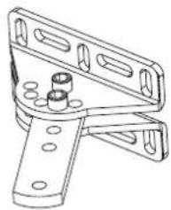
natural_image
Technical line drawing of a mechanical clamp or bracket assembly (no text or symbols)Z2 Z3
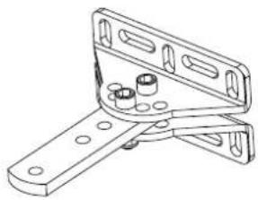
natural_image
Technical line drawing of a mechanical clamp or bracket assembly (no text or symbols)natural_image
Simple line drawing of a funnel with internal circles and a handle (no text or symbols)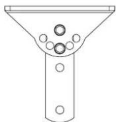
natural_image
Simple line drawing of a funnel with circular components and a handle (no text or symbols)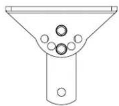
natural_image
Simple line drawing of a funnel with circular components (no text or symbols)natural_image
Technical line drawings of three different metal tools with holes, shown from different angles (no text or symbols present)EAM2, EAM3
natural_image
Technical illustration of a mechanical assembly with housing, bolts, and a shaft (no text or symbols)natural_image
Line drawing of a hand using a screwdriver to adjust or install a mechanical component (no text or symbols present)natural_image
Line drawing of a remote control device with two circular buttons and a rectangular body (no text or symbols)Important - safety information Page
1 Standard system setup....9
2 Technical data....9
3 Overall dimensions of adapter....9
4 Llimits of use....9
5 Possible positions of the bracket....10
6 Choosing the hole for securing the pivot for actuator rotation....10
7 Table with installation dimensions....12
8 Fixing the bracket to the pillar....14
9 Mounting the actuator ....13
10 Unlocking the actuator .... 13
11 Electrical wiring harnesses 13
12 User manual....14
The following safety information is an integral and essential part of the product and must be supplied to the user.
Read it carefully as it provides important guidelines regarding installation, use and maintenance. Always store this module carefully and transfer it to any subsequent users of the system. Incorrect installation or improper use of the product may constitute a serious hazard.
IMPORTANT - SAFETY INFORMATION
• Installation must be performed by professionally qualified personnel in observance of current national and European legislation.
• After removing the packaging check the condition of the device. If in doubt, consult a qualified technician.
- Packaging materials (carton, plastic bags, staples, polystyrene, etc.) must be disposed of in suitable containers and must not be dispersed into the environment. Above all they must be kept out of the reach of children.
- The installation, electrical connections and settings must be executed in accordance with sound engineering practice. Make certain that the data on the data plate conform with the mains electrical supply data and make certain that the section of the connection cables is suitable for the loads applied.
- Do not install the product in environments where there is a risk of explosion or which are disturbed by electromagnetic fields. The presence of flammable gases or fumes constitutes a serious hazard.
- Equip the mains supply with a suitable overvoltage protection device, a switch/disconnector and/or differential for the product and in conformity with the standards in force.
- Clearly indicate with an appropriate sign on the gate, door, window or barrier that they are remotely operated.
- ELVOX s.p.a. denies all liability for damage incurred when devices and/or components are used that are incompatible in terms of product integrity, safety and operation.
• This equipment must be used exclusively as specified in design; any other use is to be considered improper and therefore hazardous.
- Always disconnect the equipment from the power supply by means of the main switch or by removing the plug before performing maintenance or cleaning. Use exclusively genuine spare parts for repairs and replacements.
- The installer must provide all information regarding operation, maintenance and use of the single parts and the system as a whole.
EAM2, EAM3
1- Standard system setup
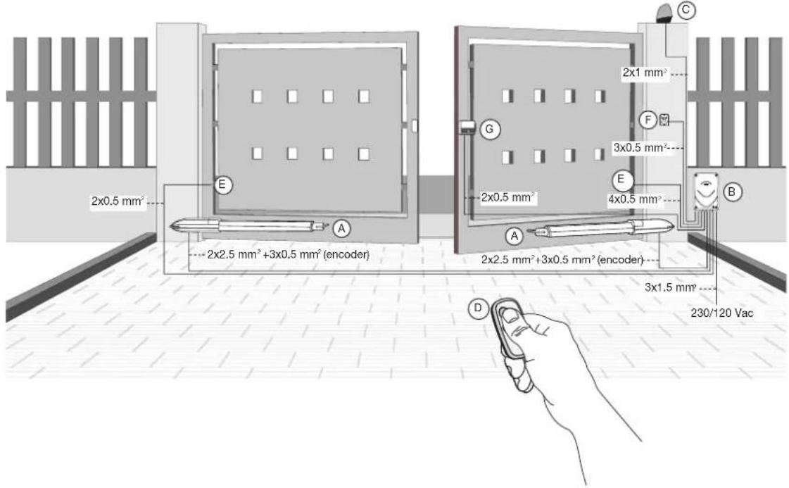
Key
A - Linear actuator
B - Control unit
C - Flashing light
D - 2-channel radio control
E - Pair of photocells
F - Selector
G - Electrical lock
2- Technical data:
| Description EAM2 EAM3 | ||
| Electric motor power supply 24 Vdc 24 Vdc | ||
| Electric motor maximum absorption 5 A 5 A | ||
| Electric motor maximum power 120 W 120 W | ||
| Maximum gate leaf length 3 metres 4 metres | ||
| Maximum gate leaf weight | 300 kg | 250 kg |
| Maximum opening | 110° | 110° |
| Opening time | Min. 10sec. Max 22 sec. | Min. 15sec. Max 25 sec. |
| Protection rating | IP44 | IP44 |
| Operating temperature | From -20 to +55°C | From -20 to +55°C |
| Dimensions | 785x110x105 mm | 925x110x105 mm |
| Weight | 9.2 kg | 10.2 kg |
| Frequency of use | 100% 100% | |
| Useful travel | 280 mm | 430 mm |
3- Dimensions and clearance of actuator EAM1 and EAM2:

4- Limitations of use EAM2:
| Length of gate leaf (metres) | Weight of gate leaf (kg) |
| 1.5 | 800 |
| 2 | 550 |
| 2.5 | 400 |
| 3 | 300 |
Limitations of use EAM3:
| Length of gate leaf (metres) | Weight of gate leaf (kg) |
| 2.5 | 550 |
| 3 | 400 |
| 3.5 | 300 |
| 4 | 250 |
EAM2, EAM3
Before installing the automation, check that:
- the hinges are sturdy and efficient and there is no strong friction
- the measurement Y is no greater than the value shown in the table of installation dimensions. In this case it is necessary to work on the pillar in order to reach this measurement
- the length of the gear motor power supply cables does not exceed 15 metres
- there are the mechanical stops which are properly secured
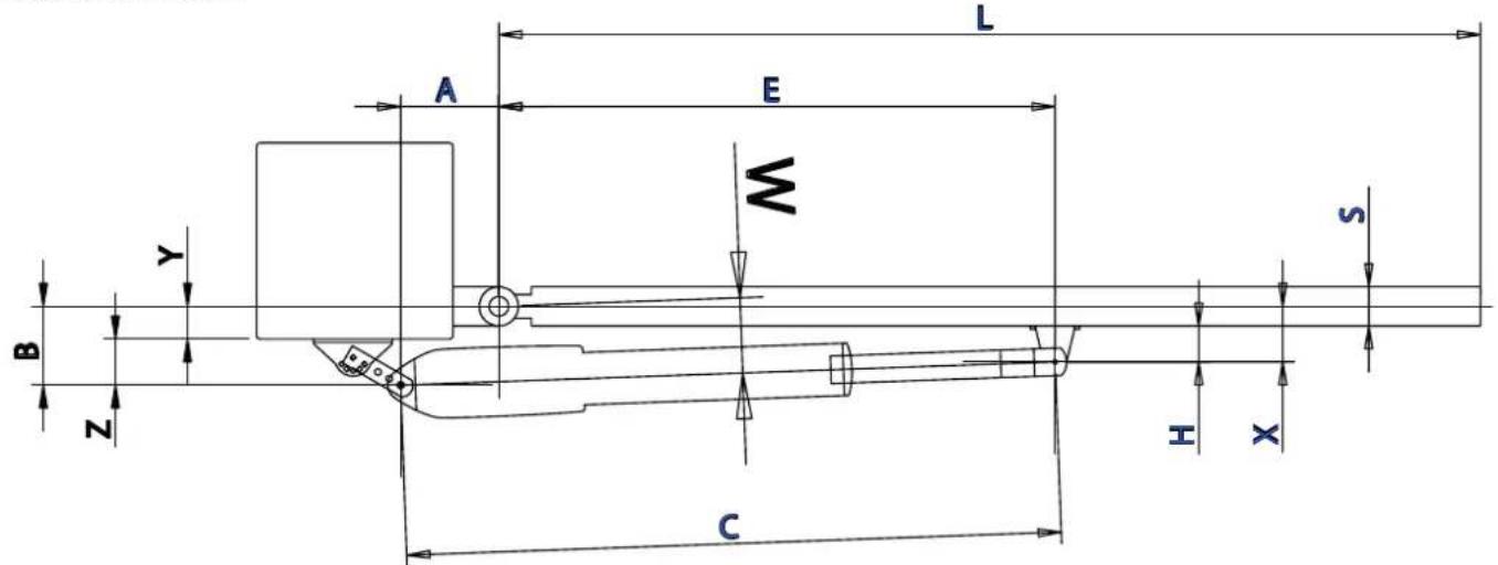
Installation dimensions:
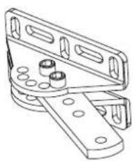
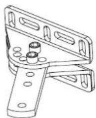
5- Possible positions of the bracket:
natural_image
Technical line drawing of a mechanical bracket or clamp assembly (no text or symbols)Z1
natural_image
Technical line drawing of a mechanical clamp or bracket assembly (no text or symbols)Z2 Z3
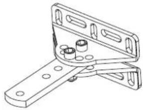
natural_image
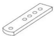
Technical line drawing of a mechanical bracket with mounting holes and bolts (no text or symbols)6- Choice of the hole for securing the pivot for actuator rotation:
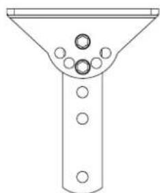
natural_image
Simple line drawing of a funnel with circular holes and a central shaft (no text or symbols)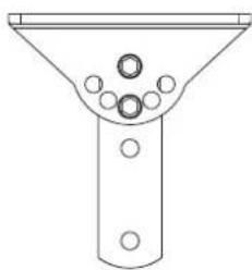
natural_image
Simple line drawing of a funnel with circular holes and a central shaft (no text or symbols)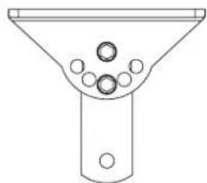
natural_image
Simple line drawing of a funnel with internal circles and a base (no text or symbols)N.B. If using hole F2 or F3, it is necessary to cut the bracket, see figure:
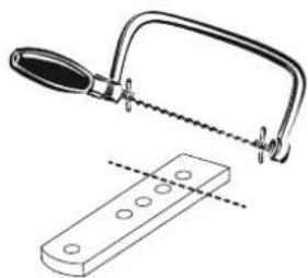
natural_image
Technical line drawing of a saw cutting tool and a rectangular base with holes (no text or symbols)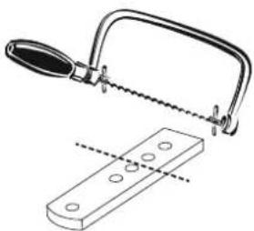
natural_image
Technical illustration of a hand saw cutting through a metal bracket (no text or symbols)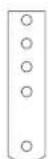
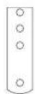
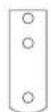
EAM2, EAM3
7- Table with installation dimensions EAM2:
| Maximum opening | Y (mm) Position of bracket and hole | A (mm) B (mm) E (mm) C (mm) H (mm) | ||
| 90° 20 Z2-F1 140 134 885 1026 55 | ||||
| 90° 30 Z2-F1 130 134 895 1026 55 | ||||
| 90° 40 Z2-F2 140 137 885 1026 55 | ||||
| 90° 50 Z2-F2 130 147 895 1026 55 | ||||
| 90° 60 Z2-F3 135 140 890 1026 55 | ||||
| 90° 70 Z1-F2 130 133 895 1026 55 | ||||
| 90° 80 Z1-F2 130 143 895 1026 55 | ||||
| 110° 20 Z1-F1 135 92 890 1025 55 | ||||
| 110° 30 Z1-F2 135 93 890 1025 55 | ||||
| 110° 40 Z1-F2 135 103 895 1030 55 | ||||
| 110° 50 Z1-F2 135 113 890 1025 55 | ||||
| 110° 60 Z1-F2 125 123 900 1025 55 |
Choose the installation dimensions according to the measured distance Y.
Table with installation dimensions EAM3:
| Maximum opening | Y (mm) Position of bracket and hole | A (mm) B (mm) E (mm) C (mm) H (mm) | ||||
| 90° 20 Z3-F1 270 | 150 1050 1322 | 55 | ||||
| 90° 30 Z3-F1 270 | 160 1050 1322 | 55 | ||||
| 90° 40 Z3-F1 260 | 170 1060 1322 | 55 | ||||
| 90° 50 Z3-F1 250 | 180 1070 1323 | 55 | ||||
| 90° 60 Z3-F1 245 | 190 1080 1324 | 55 | ||||
| 90° 70 Z3-F1 230 | 200 1090 1325 | 55 | ||||
| 90° 80 Z3-F1 220 | 210 1100 1325 | 55 | ||||
| 110° 20 Z3-F1 200 | 150 1120 1321 | 55 | ||||
| 110° 30 Z3-F1 200 | 160 1120 1322 | 55 | ||||
| 110° 40 Z3-F1 190 | 170 1130 1322 | 55 | ||||
| 110° 50 Z3-F2 200 | 160 1120 1322 | 55 | ||||
| 110° 60 Z2-F2 200 | 157 1120 1322 | 55 | ||||
| 110° 70 Z2-F3 210 | 150 1115 1326 | 55 | ||||
| 110° 80 Z2-F3 200 | 160 1125 1327 | 55 |
Choose the installation dimensions according to the measured distance Y.
EAM2, EAM3
8- Secure the bracket to the pillar, following the dimensions given in the table.
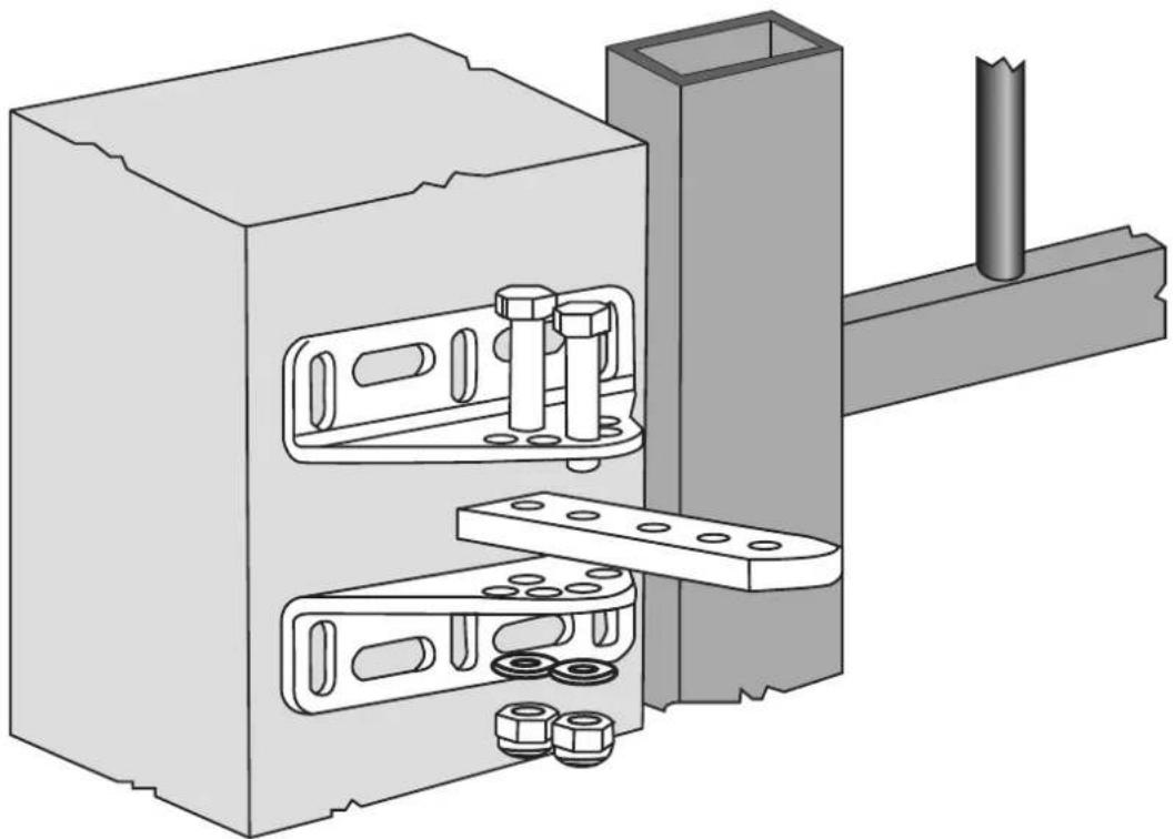
natural_image
Technical illustration of a mechanical assembly with housing, bolts, and a pipe (no text or symbols)9- Mounting the actuator:
Position the actuator, secure the anchoring screw and check the actuator level.
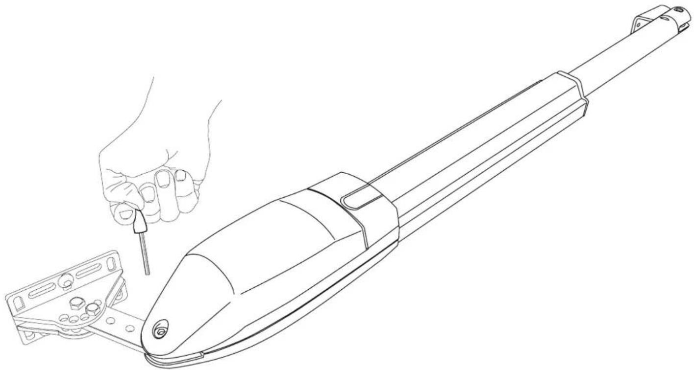
natural_image
Line drawing of a hand using a tool to adjust or install a mechanical component (no text or symbols present)Secure the bracket for anchoring the gate leaf (see dimension E in the table)
EAM2, EAM3
10- Unlocking the actuator:
open the sliding door (A), insert the key, turn it anticlockwise (B) and remove the cover (C). Turn the unlocking lever 180° anticlockwise.
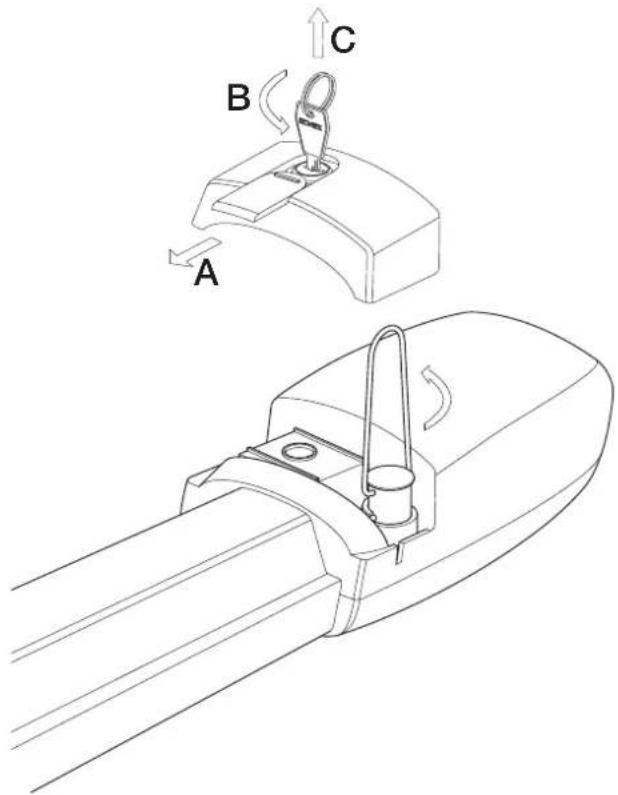
With the actuator unlocked, manually simulate opening and closing completely. There must be no strong mechanical friction during this movement. N.B.: Check for the presence and tightness of the mechanical stops on both opening and closing. Should the gate leaf exceed a length of 2 metres it is necessary to install the electrical lock.
11- Electrical wiring harnesses:
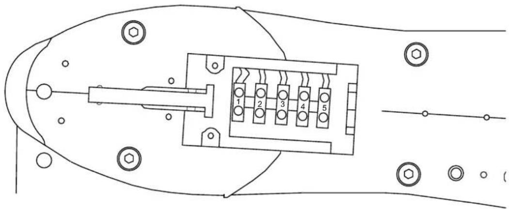
Open the cover of the compartment for the electrical wiring harness, take out the terminal block and do the wiring according to the diagram:
natural_image
Technical line drawing of a mechanical component with numbered pins and mounting holes (no text or symbols)| Terminal number Wire colour Description | |
| 1 Unleaded Encoder signal | |
| 2 White Encoder supply voltage negative (GND) | |
| 3 Red Encoder supply voltage positive (+12 Vdc) | |
| 4 Brown Motor supply voltage (closing) | |
| 5 White Motor supply voltage (opening) |
The electrical wiring between the control unit and the actuator must not exceed 15 metres.
EAM2, EAM3
12- User Manual (User operation)
Manual unlocking: open the sliding door (A), insert the key, turn it anticlockwise (B) and remove the cover (C). Turn the unlocking lever 180° anticlockwise.
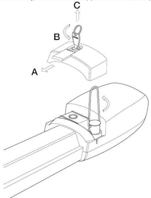
- To re-lock the gate leaf turn the lever clockwise. - In the event of mains power failure, the back-up battery ensures the operation of the automatic gate system for a limited period. In the event of a flat or missing battery, manually unlock the actuator, it is advisable to move the gate into the fully open position and reset unlocking by turning the lever clockwise and close the cover, which is to prevent any unwanted movement of the gate (with the actuator unlocked the gate leaf is free to move, which could cause damage to property or persons). Once the power supply is restored, the electronic board will charge the back-up battery and the gate will return to normal operation after a command pulse.
CAUTION: Unlock and reset with the gate stationary, do not leave the unlocking compartment without a cover.
Maintenance: Periodically check the fixing screws, the integrity of the connecting cables, the correct functioning of the safety systems (photocells and sensitive edges), the robustness of the mechanical stops and the soundness of the systems for supporting the gate leaf (hinges or bearings). Every 2 years it is recommended to replace the batteries in the remote control.
Location of the buttons for controlling the gate (selectors, keypads, buttons, etc.)
| Control device Location | |
Association of the remote control buttons
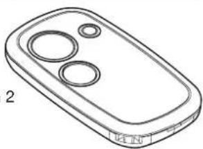
| Button | Not used | Controls total opening of the gate | Controls partial opening of the gate | Controls second channel output |
| Button 1 | ||||
| Button 2 |
If the automatic closing function is active (when the gate is stationary and open the flashing light stays on) the gate closes after the set time. You can disable this function by pressing the button on the remote control before the gate reaches the fully open position. If the sequential function is active it opens-stops-closes.
If the gate meets an obstacle on closing, and automatic closing is active, the control unit makes 5 attempts at closing, after which it remains open. In this case it is necessary to remove the obstacle from its path and control the gate with the transmitter and button so that it closes completely at low speed.
button 1
natural_image
Line drawing of a remote control device with two circular buttons and a labeled terminal (no text or symbols on the device itself)button 2
EC DECLARATION OF CONFORMITY
(Declaration of incorporation of partly completed machinery Annex IIB Directive 2006/42/EC)
No.: ZDT00439.00
The undersigned, representing the following manufacturer
Elvox SpA
Via Pontarola, 14/A
35011 Campodarsego (PD) Italy
herewith declares that the products
ACTUATORS FOR SWING GATES - EKKO SERIES
Articles EAM1 (EKKO 200D), EAM2 (EKKO 250D), EAM3 (EKKO 350D)
are in conformity with the provisions of the following EU Directive(s) (including all applicable amendments) and that all of the following standards and/or specifications have been applied
EMC Directive 2004/108/EC: EN 61000-6-1 (2007), EN 61000-6-3 (2007) + A1 (2011)
Machinery Directive 2006/42/EC EN 60335-2-103 (2003) + A11 (2009)
EN 13241 (2003) + A1 (2011), EN 12453 (2000)
He also declares that the product must not be commissioned until the end machine, in which it is to be incorporated, has been declared in conformity, when applicable, with the provisions of Directive 2006/42/EC.
He declares that the relevant technical documentation has been constituted by Elvox SpA, drawn up in accordance with Annex VIIB of Directive 2006/42/EC and that the following essential requirements have been fulfilled: 1.1.1, 1.1.2, 1.1.3, 1.1.5, 1.1.6, 1.2.1, 1.2.2, 1.2.6, 1.3.1, 1.3.2, 1.3.3, 1.3.4, 1.3.7, 1.3.8, 1.3.9, 1.4.1, 1.4.2, 1.5.1, 1.5.2, 1.5.4, 1.5.5, 1.5.6, 1.5.7, 1.5.8, 1.5.9, 1.6.1., 1.6.2, 1.7.1, 1.7.2, 1.7.3, 1.7.4.
He undertakes, in response to an adequately justified request from the national authorities, to present all the necessary supporting documentation concerning the product.
Campodarsego, 02/05/2013
The Chief Executive Officer
Note: The contents of this declaration match what was declared in the latest revision of the official declaration that was available before this manual was printed. This text has been adapted for editorial purposes. A copy of the original declaration can be required to Elvox SpA
Brand : Vimar
Model : ELVOX EAM3
Category : Intercom