
FL204 - Measurement Aerospace Logic - Free user manual and instructions
Find the device manual for free FL204 Aerospace Logic in PDF.


| Product Type | Fuel Level Instrument (Digital Senders) |
| Model Number | FL204D (for four tanks) |
| Number of Tanks Supported | 4 |
| Sender Type | TSO C55a Qualified Digital Senders (magnetoresistive, P/N CC284022) |
| Input Voltage | 6 - 36 VDC |
| Power Consumption | 100 mA (0.1 A) |
| Display | Sunlight-readable LCD, 80/80/80/80 degree viewing angle |
| Fuel Quantity Accuracy | AS405C +/- 1 US Gallon |
| Frequency Input Range | 10 Hz - 300 Hz |
| Weight (excluding harness) | 4.05 oz (115 g) |
| Dimensions | Standard 2.25 in (57.15 mm) round panel mount |
| Material / Finish | Black anodized 6061 aluminum |
| Interface Connector | DB-25 |
| Intensity Control | Internal or external (0V to bus voltage via BLUE wire) |
| Annunciator Output | 100 mA sink with reverse EMF protection |
| Operating Temperature Range | -15°C to +55°C (constant), -40°C to +70°C (short term) |
| Storage Temperature Range | -55°C to +85°C |
| Software Compliance | DO-178B |
| Environmental Compliance | DO-160F |
| Certification | TSO C55a, Transport Canada approved |
| Calibration Required | Yes, per two-gallon increments starting from unusable fuel |
| Functions | Fuel level display per tank, trend graph (130 min history), low fuel warning, self-test |
| Warranty | 12 months from manufacture date; out-of-warranty flat rate 50% of new cost |
Frequently Asked Questions - FL204 Aerospace Logic
User questions about FL204 Aerospace Logic
0 question about this device. Answer the ones you know or ask your own.
Ask a new question about this device
Download the instructions for your Measurement in PDF format for free! Find your manual FL204 - Aerospace Logic and take your electronic device back in hand. On this page are published all the documents necessary for the use of your device. FL204 by Aerospace Logic.
USER MANUAL FL204 Aerospace Logic
This document set is applicable to the following part number configurations:
 | ||
| Part Number | Description | |
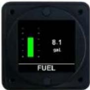
| FL201D | Fuel level instrument for digital senders, one tank | |
 | Part Number | Description |
| FL202D | Fuel level instrument for digital senders, two tanks | |
 | Part Number | Description |
| FL203D | Fuel level instrument for digital senders, three tanks | |
 | Part Number | Description |
| FL204D | Fuel level instrument for digital senders, four tanks | |
 | Part Number | Description |
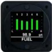
| FL205D | Fuel level instrument for digital senders, five tanks | |
 | Part Number | Description |
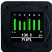
| FL206D | Fuel level instrument for digital senders, six tanks | |
THIS IS A TRANSPORT CANADA APPROVED MANUAL
The following checklist outlines the required articles for all FL20XD series part numbers.
| Documentation | Document Number | |
| ☐ | Introduction (this document) | S200-FL20XD-001 |
| ☐ | Warranty Statement | S200-AWS |
| ☐ | Installation Instructions | S200-FL20X-002 |
| ☐ | Intensity Control Installation Options | S200-DDC-INST |
| ☐ | Wiring and Installation Schematic | S200-FL20X-003 |
| ☐ | Human Interface Definition | S200-HID |
| ☐ | Instrument Setup | S200-FL20X-004 |
| ☐ | Operations Guide | S200-FL20XD-005 |
| ☐ | Product Specifications | S200-FL20XD-006 |
| ☐ | Installation Compliance | S200-FL20X-007 |
| ☐ | Instructions for Continued Airworthiness | S200-ICA |
| ☐ | Flight Manual Supplement | S200-FMS (if applicable) |
| ☐ | Calibration Log | S200-FL20XD-0XX |
| ☐ | Authorized Release Certificate | FORM ONE |
| ☐ | Permission to Use STC | S200-PTU |
| ☐ | Canadian STC and Eligibility List | STC & S200-CEL |
| ☐ | FAA STC and Approved Model List | STC & S200-AML |
Components
□ FL20XD Instrument
□ 4 X Mounting Screws
The Fastest Way To Install And Start Using This Product
NOTE: This product is certified as a primary replacement, new or secondary instrument only when installation is performed in accordance with the documented instructions and procedures.
- Review the Warranty Statement before performing any tasks. Do not remove the instrument from the sealed package until you agree with the stated terms.
- If this instrument is to be installed in a certified aircraft, verify that the aircraft model is listed on the Eligibility List (Canadian registered aircraft) or the Approved Model List (USA and all other countries).
If it is NOT listed, contact your local authority and obtain the necessary requirements or approvals before proceeding further.
For all other vehicles, including experimental aircraft continue with Step 3.
- Follow the Installation Instructions exactly as noted, referring to the Wiring Diagram as and when required. Note: The installation process has been optimized based on the sequence of components to be installed. Installing the product in any other way will, in all likelihood, take longer and be more complex.
Ensure that one of the Intensity Control options has been installed in accordance with document # S200-DDC-INST.
- Perform the Instrument Setup using the required data as listed in the Instrument Setup procedure.
- Validate that all functions perform as outlined in the Operations Guide.
- Complete all regulatory documentation, if required.
Aerospace Logic Inc
NO NONSENSE WARRANTY
Our warranty policy is simple .... It is even written in plain English!
Please read it BEFORE DOING ANYTHING WITH YOUR NEW INSTRUMENT!
If you require technical support when installing your instrument please call our Technical Support department directly on 416-628-0725
We will:
- Repair or replace (at our discretion) any instrument which becomes defective within a period of 12 (twelve) months of manufacture date. You will pay for the shipping costs to return the instrument to us and we will pay for the shipping costs to return the instrument to you;
- Replace all instruments that fail out of warranty for a flat rate of 50% of the cost of a new instrument, at the time of the failure.
We are not:
- Liable for any costs associated with the installation or removal of any of our instruments, irrespective of the cause:
- Liable for any misuse or non-use of the instrument in whatever form.
We will not:
- Repair or replace your instrument free of charge, under warranty, if it has not been installed by an appropriately licensed person.
If you do not agree with ANY of the above statements, return your new instrument to us immediately for a FULL refund LESS shipping costs.
ALL RETURNS REQUIRE RETURN MATERIAL AUHORIZATIONS (RMA). WE DO NOT ACCEPT RETURNS WITHOUT RMA NUMBERS. CALL 416-628-0725 FOR AUTHORIZATION.
- The FL20X instrument uses resistive, float type senders for fuel level sensing. Ensure that all senders are in a good working condition BEFORE proceeding to step 2.
a. FL20X instruments use the existing aircraft fuel senders. For tanks with multiple senders, ensure that the senders are connected in series with the outermost sender in the series being grounded. The sender array must represent a varying resistance with relationship to fuel level and NOT be powered from any source.
b. FL20XD instruments use magnetoresistive aircraft fuel senders P/N CC284022-()-(). Install in accordance with the manufacturer supplied instructions for these senders. - Connect the wiring supplied with the DB25 interface connector in accordance with the FL20X Wiring and Installation Schematic. DO NOT ATTACH THE CONNECTOR TO THE INSTRUMENT UNTIL ALL WIRING HAS BEEN CONNECTED.
- Select the instrument location in the aircraft panel.
- Ensure that the aircraft master switch and/or power to the instrument is OFF.
- Attach the DB25 connector to the instrument. Ensure that the plug is fully inserted into the instrument. Finger tighten the two plug locking screws, then tighten 1/8 turn using a screwdriver. DO NOT OVERTIGHTEN.
- The instrument can be installed with the DB25 connector orientated to the TOP or BOTTOM of the instrument panel.
- Install the instrument in the panel, attaching with four 6-32 X 5/16" screws.
- Initial Power Up Sequence:
a. Adjust the instrument intensity control for maximum intensity.
b. Apply power to the instrument.
c. The instrument display will turn on. Ignore the orientation at this time.
d. Turn the instrument OFF.
- If the instrument display does not turn on:
a. Ensure intensity control is set for maximum.
b. Turn off power.
c. Disconnect the DB25 connector from the instrument.
d. Check intensity control.
e. Check the wiring installation and breaker or fuse.
- Proceed to "Instrument Setup".
Choose ONE of the options listed below for connection of the BLUE intensity control wire from the instrument harness.
Theory of Operation
- The instrument intensity control is voltage sensitive.
- When the sense input is grounded the instrument display will be at the dimmest intensity. At bus voltage the instrument display will be at the brightest intensity.
• Voltages between these two will vary the display intensity.
1. Preferred Method – Independent Potentiometer
Connect the BLUE wire to P/N A200-POT Rev. 02 as below:
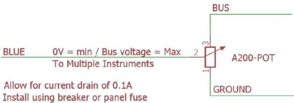
Ensure the "EXTERNAL" option in the Dimmer Control menu is set.
2. Connection of Existing Panel Intensity Control
Confirm the existing panel lighting control meets the following requirements:
- When set for DAY operation BUS voltage must be output.
- When used at NIGHT the output must vary from 0V (Ground) to BUS voltage.
If these requirements are met connect the BLUE wire to the panel lighting control.
Ensure the "EXTERNAL" option in the Dimmer Control menu is set.
3. Day VFR Operation
Do not connect the BLUE wire. Set the intensity using the internal Dimmer Control. Refer to document S200-HID, Intensity Control section for menu access instructions.

flowchart
graph TD
    A["FL20X INSTRUMENT"] --> B["DE25 CONNECTOR"]
    B --> C["COLOR DESCRIPTION"]
    C --> D["RED"]
    C --> E["BLACK"]
    C --> F["BLUE 0V BUS VOLTAGE - VARIABLE INTENSITY INPUT *"]
    C --> G["ORANGE"]
    G --> H["6V - 36V SUPPLY"]
    G --> I["GROUND"]
    G --> J["EXTERNAL ALARM (MAX 100mA SINK)"]
    B --> K["COLOR/TAG TANK NAME (DISPLAYED)"]
    K --> L["WHITE / #1"]
    K --> M["WHITE / #2"]
    K --> N["WHITE / #3"]
    K --> O["WHITE / #4"]
    K --> P["WHITE / #5"]
    K --> Q["WHITE / #6"]
    K --> R["TANKS NUMBERED LEFT TO RIGHT\nNUMBER OF WHITE WIRES TO MATCH TANK CONFIGURATION"]
    R --> S["1 (FUEL / LEFT / 1)"]
    R --> T["2 (RIGHT / 2)"]
    R --> U["3 (3)"]
    R --> V["4 (4)"]
    R --> W["5 (5)"]
    R --> X["6 (6)"]
    R --> Y["NOTES:\n1. * See S200-DDC-INST for additional intensity control options\nSENDER NOTES:\nResistance greater than 10 and less than 300 ohms1.\nFrequency input greater than 10Hz and less than 300Hz\n2. Multiple resistive senders per tank to be connected in series\n3. Qualified for use with OEM or STCD senders only"]
    A --> Z["INSTALLATION NOTES:\n1. Allow for current drain of 0.1A (100mA)\n2. Install using breaker or panel fuse\n3. Maximum 7 instruments per 1A of breaker capacity\n4. For multiple instrument installations install breakers to comply with redundancy requirements of AC 23.1309-1D Appendix 1"]
    Z --> AA["(C) Aerospace Logic Inc. (2008-2017)"]
(C) Aerospace Logic Inc. (2008-2017)
FL20X Wiring and Installation Schematic
5200-FL20X-003 Rev 1.4 02/28/2017
All 200 Series instruments have been designed around a standard Human Interface protocol. This allows identical operation of the two panel switches between all instruments while still allowing multiple functions. This document is a generic outline of the functionality of the switches, based on the various functional states of the instrument.
Top Button
The top button is the action button. It invokes different screen displays, allows selection of values and increments or decrements values. Examples of these actions are:
- Moving between display screens
- Selection of an action from a menu
- Changing a value from within the setup menus
- Entering a value during flight (clock instrument only)
Bottom Button
The bottom button is the navigation button. It will allow the cursor on the screen to move between allowable selections. Examples of these actions are:
- Selection of different cylinders (EGT and CHT) in the Single Cylinder mode
- Selection of different tanks (Fuel Level)
- Selection of limits and functional items from within the setup menus
- Time field selection (clock instrument only)
There is one exception to the functionality of the bottom button. This is from the Primary Display (the screen that first comes on from power up). Pressing the button will display the instrument core status and support data.
General
- Each instrument contains detailed button options in the Operations Guide.
- During setup, instructions are provided on screen and use of the buttons is as noted in this document.
Intensity Control
Press and hold the top button for 5 seconds to activate the Dimmer Control menu.
Select the "Up Arrow" and press the top button to disable external intensity and increase intensity. Select the "Down Arrow" and press the top button to decrease the intensity and enable external intensity control.
Select the "Save" option and press the top button to save your selection and return to normal operations.
The Dimmer Control menu is not available during instrument setup.
- Before proceeding with the instrument setup you will require the following information, for each tank pair or set, as it pertains to the aircraft that the instrument is being installed on:
a. Maximum red line fuel quantity
b. Maximum yellow line fuel quantity
- This information must be obtained from a current, traceable source for the aircraft that the instrument is being installed on. Some possible sources are:
a. Pilot Operating Handbook
b. Maintenance Manual
c. Aircraft Type Certificate Data Sheet
d. Engine Type Certificate Data Sheet
e. Manufacturer
- This instrument requires calibration before it will function. To calibrate each tank you will be required to add fuel at TWO gallon increments, starting with the unusable fuel in the tank (the legal, zero fuel point).
a. Place the aircraft in a level flight attitude and support the aircraft wings, if necessary.
b. Drain all tanks to be calibrated.
c. Disable any cross feed between tanks.
d. Place the unusable fuel in each tank to be calibrated.
e. Complete the calibration process by following the interactive, instructions provided throughout the process on the instrument display (See 4).
f. Calibration time is approximately one minute per two gallons of fuel.
g. Note the calibration values on the provided calibration sheets. This value serves two purposes.
i. It demonstrates a compliant installation, and
ii. Provides a hard copy backup of all calibration data.
h. It is not necessary to complete the full calibration at once. Calibration can be resumed at any point of the process by re-entering the setup.
- To enter parameters and perform the calibration, proceed as follows:
a. Turn off the power to the instrument
b. Press and hold both top and bottom buttons and turn on the power to the instrument.
c. When instructed, release both buttons.
d. In the setup menus, use the bottom button to navigate and the top button to select an option.
e. Follow the onscreen instructions to enter the correct operating parameters. NOTE: Depending on the installation orientation of the instrument the display may initially be upside down. The first prompt in the setup is to press the button at the top of the instrument. This will orientate it correctly.
f. To perform the instrument calibration, follow the instructions provided on the instrument screen.
- Once all calibration has been completed the instrument will be enabled and be ready for use.
This manual outlines the operating procedures for all FL20XD series products
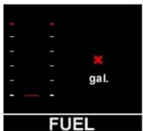


FUEL INSTRUMENT NOT INSTALLED CORRECTLY FLIGHT PROHIBITED
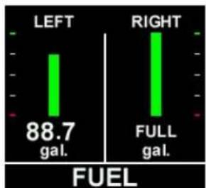
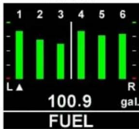
1. Power Up / Default Screen
Displays the fuel level in each tank. Colors are determined by the range values as set during installation. Tanks are indicated from leftmost to rightmost.
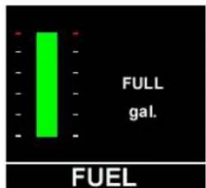
FUEL FL201D
bar
| Direction | Value (gal.) | | :--- | :--- | | LEFT | 88.7 | | RIGHT | Full gal. |FUEL FL202D

bar
| Category | Value | |---|---| | 1 | 95.4 | | 2 | 95.4 | | 3 | 95.4 |FUEL FL203D

bar
| Category | Value | |---|---| | 1 | L | | 2 | 91.7 | | 3 | (labeled) | | 4 | gal. |FL204D

bar
| Category | Value | |---|---| | 1 | 98.9 gal. | | 2 | 98.9 gal. | | 3 | 98.9 gal. | | 4 | 98.9 gal. | | 5 | 98.9 gal. |FL205D
bar
| Category | Value | |---|---| | 1 | L▲ | | 2 | | | 3 | | | 4 | | | 5 | | | 6 | | | 100.9 gal. (FUEL) | |FL206D
For the FL201D and FL202D instrument, the tank quantity is permanently displayed beneath indicator bar. For all other instruments, use the bottom button to scroll between tanks. The fuel quantity displayed corresponds to the tank number with the arrow beneath the bar indicator.
Press the top button to move to the next display screen.
2. Trend Graph
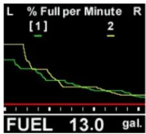
line
| FUEL | % Full per Minute | | ---- | ----------------- | | 13.0 | gal. |This screen provides a graphical display of fuel usage, since the most recent power on.
The graph spans a time period of 130 minutes (2 hours 10 minutes). Once this graph area has been populated it will scroll to the left.
The fuel value displayed at the bottom of the screen relates to the selected tank as indicated
by the bracketed tank number at the top of the screen. Use the bottom button to scroll between tanks.
Press the top button to return to the default screen.
3. Other Options
To display the instrument serial number and core information press and hold the bottom button when the instrument is first powered on.
WARNING
NEVER RELY SOLELY ON ANY FUEL INDICATION INSTRUMENT FOR THE DETERMINATION OF AVAILABLE FUEL.
WHEN USED IN CONJUNCTION WITH A PHYSICAL INSPECTION, DETERMINATION OF AVAILABLE FUEL PLUS NECESSARY FLIGHT DURATION AND CONDITION CALCULATIONS, A FUEL LEVEL INSTRUMENT BECOMES A VALUABLE COCKPIT INFORMATION RESOURCE.
WARNING
All operations are to be performed in accordance with the specific instructions pertaining to your aircraft, including those provided by the engine manufacturer. The FL20X series instruments are only parameter reporting devices which can assist in engine and flight management when used in conjunction with these instructions.
All FL20X products are certified as primary replacements ONLY, within the limits as described above. THEY MAY NOT BE INSTALLED AS SECONDARY INSTRUMENTS.
Certification / Compliance
| TSO | C55a |
| Environmental | DO-160F |
| Software | DO-178B |
| A1CAASXXXXXXXXZBXXBBBCSBA1C11XXAX |
DC Power Source
| Input voltage | 6 to 36 VDC |
| Power consumption | 100mA |
| Load dump tolerance | +60V |
| Direct spike tolerance | +/- 60V |
| Cable spike tolerance | > +/- 1KV |
Operating Temperature
| Constant operating | -15°C to +55°C |
| Short term operating (1hr) | -40°C to +70°C |
| Storage | -55°C to +85°C |
Signal Input
| 5.0V Pulse Width Modulated (10Hz-300Hz) |
Sender Type
| TSO C55a Qualified Digital Senders |
Display
| Fuel Quantity | US Gallons or Litres |
Accuracy
| Fuel Quantity | AS405C +/- 1 USG |
| Frequency | +/- 0.1Hz |
Range
| 0 to 120 USG (defined by fuel sender/tank size) |
Display
| Sunlight readable LCD |
| 80/80/80/80 Degree viewing angle |
Annunciator Output
| 100mA sink with reverse EMF protection |
Interface Connector
| DB-25 |
Software Functionality
| Primary | Fuel level in all tanks |
| Trend Graph |
| Graphic display of level vs time |
Dimensions
Weight (excluding harness)
| 4.05 oz |
Finish
| Black anodized 6061 aluminum |
1. Installation Procedures and Limitations
Should your specific aircraft not be listed on our STC Approved Model List (AML), contact your local FSDO or flight authority for installation requirements BEFORE commencing any installation tasks.
Installation must be in accordance with the following FL20X published documents:
a. Installation Instructions,
b. Wiring and Installation Schematic, and
c. Instrument Setup.
2. Installation Location and Visibility
The products are to be installed in existing panel holes and will replace existing instrumentation. As primary replacement products it is recommended and preferred that they be placed in the same panel location as the original equipment. Their visibility and placement relative to other instruments are the same or similar to the existing instruments. Where they are installed in a different location it is the responsibility of the installer to ensure that they are visible to the pilot under all conditions.
3. TSO COMPLIANCE NOTICE
The conditions and tests required for TSO approval of this instrument are minimum performance standards. Those installing this instrument on or in a specific type or class of aircraft, must determine that the aircraft installation conditions are within the TSO standards. TSO articles must have separate approval for installation in an aircraft. The instrument may be installed only according to 14 CFR part 43 or the applicable airworthiness requirement.

- THIS IS A TRANSPORT CANADA APPROVED MANUAL
- Components
- The Fastest Way To Install And Start Using This Product
- Aerospace Logic Inc
- NO NONSENSE WARRANTY
- Please read it BEFORE DOING ANYTHING WITH YOUR NEW INSTRUMENT!
- If you require technical support when installing your instrument please call our Technical Support department directly on 416-628-0725
- We will:
- We are not:
- We will not:
- If you do not agree with ANY of the above statements, return your new instrument to us immediately for a FULL refund LESS shipping costs.
- ALL RETURNS REQUIRE RETURN MATERIAL AUHORIZATIONS (RMA). WE DO NOT ACCEPT RETURNS WITHOUT RMA NUMBERS. CALL 416-628-0725 FOR AUTHORIZATION.
- Theory of Operation
- Preferred Method – Independent Potentiometer
- Connection of Existing Panel Intensity Control
- Day VFR Operation
- FL20X Wiring and Installation Schematic
- Top Button
- Bottom Button
- General
- Intensity Control
- Power Up / Default Screen
- Trend Graph
- Other Options
- WARNING
- NEVER RELY SOLELY ON ANY FUEL INDICATION INSTRUMENT FOR THE DETERMINATION OF AVAILABLE FUEL.
- WHEN USED IN CONJUNCTION WITH A PHYSICAL INSPECTION, DETERMINATION OF AVAILABLE FUEL PLUS NECESSARY FLIGHT DURATION AND CONDITION CALCULATIONS, A FUEL LEVEL INSTRUMENT BECOMES A VALUABLE COCKPIT INFORMATION RESOURCE.
- Installation Procedures and Limitations
- Installation Location and Visibility
- TSO COMPLIANCE NOTICE
Brand : Aerospace Logic
Model : FL204
Category : Measurement