
AMP160XL - Receiver Proel - Free user manual and instructions
Find the device manual for free AMP160XL Proel in PDF.


| Product Type | Professional Mixer Amplifier |
| Model | AMP160XL |
| Output Power RMS | 160W |
| Inputs | 4x MIC/LINE balanced (with 48V phantom), 3x AUX (selectable), 1x MAIN IN |
| Input Sensitivity | MIC: -40dBV / 600Ω; LINE: 0dBV / 100kΩ; AUX: 0dBV / 47kΩ; MAIN IN: 0dBV / 10kΩ |
| Signal Outputs | PRE OUT (1V / 600Ω), REC OUT (1V / 600Ω), BAL OUTPUT (1V / 600Ω) |
| Controls | Master Volume, Treble Tone, Bass Tone, 4x MIC/LINE Volume, AUX Volume |
| Loudspeaker Outputs | 100V / 70V / 4Ω (terminal block) |
| Frequency Response | 80Hz – 16kHz (-3dB) |
| Distortion (THD) | < 0.5% (@ 1kHz, nominal power) |
| Signal-to-Noise Ratio | MIC: ≥70dB; LINE: ≥70dB; AUX: ≥80dB |
| Power Supply | Auto-switch 100-240V~ 50/60Hz, 160VA |
| Operating Temperature | 0°C – 40°C |
| Dimensions (WxHxD) | 439 x 44 x 278 mm (19" rack-mountable with included adapters: 483 x 44 x 278 mm) |
| Weight | 5 kg |
| Key Features | VOX priority per input, Chime with routing and level, 48V phantom power, Dry contact muting, SMPS technology, 1U rack design |
| Maintenance & Cleaning | Clean exterior with compressed air or damp cloth; do not use solvents. No user-serviceable parts inside. |
| Safety | Do not expose to rain or moisture. Disconnect power when not in use. Use only with grounded outlets. Refer servicing to qualified personnel. |
| Spare Parts & Repairability | No user-serviceable parts. Contact authorized service center for any issues. |
| Package Contents | Amplifier, rack adapters, power cable, operating manual |
Frequently Asked Questions - AMP160XL Proel
User questions about AMP160XL Proel
0 question about this device. Answer the ones you know or ask your own.
Ask a new question about this device
Download the instructions for your Receiver in PDF format for free! Find your manual AMP160XL - Proel and take your electronic device back in hand. On this page are published all the documents necessary for the use of your device. AMP160XL by Proel.
USER MANUAL AMP160XL Proel
fig.1
1. POWER
flowchart
graph LR
    A["PROCESSOR"] --> B["PRODIVE"]
    A --> C["AMP Pi"]
| Model: | AMP160XL |
| Output power RMS | 160W |
| Inputs | 4xMIC/LINE balanced3 AUX (selectable)1x MAIN IN (normally connected to PRE OUT) |
| Input Sensitivity | MIC: -40dBV / 600 Ω balanced (with 48Vphantom)LINE: 0dBV / 100 KΩ balancedAUX: 0dBV / 47 KΩ unbalancedMAIN IN: 0dBV / 10KΩ unbalanced |
| Signal Output | PRE OUT (normally connected to MAIN IN)PRE OUT: 1V / 600 ΩREC OUT: 1V / 600 ΩBAL OUTPUT:1V / 600 Ω |
| Controls | MASTER VOLUME CONTROL1 TREBLE TONE CONTROL1 BASS TONE CONTROL4 MIC/LINE VOLUME CONTROLS1 AUX VOLUME CONTROL |
| Loudspeakers outputs | 100/70V/4Ω |
| Frequency response | 80Hz -16KHz (-3dB) |
| Distortion (THD) | < 0.5% (@ Pnom 1KHz) |
| S/N Ratio | MIC: ≥70dBLINE: ≥70dBAUX: ≥80dB |
| Power Supply | autoswitch 100-240V~ 50/60Hz |
| Operating temperature | 0 -40°C |
| Input/Output Connectors | terminal blockRCA |
| Power Consumption | 160VA |
| Dimensions (LxHxP) | 439 x 44 x 278 mm483 x 44 x 278 mm - 1U rack19" |
| Weight | 5 Kg |

CAUTION: To reduce the risk of electric shock do not remove cover (or back panel). No user serviceable parts inside. Refer servicing to qualified personnel only.
WARNING: To reduce the risk of fire or electric shock, do not expose this apparatus to rain or moisture.

This symbol is intended to alert the user of the presence of uninsulated dangerous voltage within the product enclosure that may be of sufficient magnitude to constitute a risk of electric shock to persons.

This symbol is intended to alert the user of the presence of important operating and maintenance (servicing) instruction in the literature accompanying the appliance. Please carefully read the owner's manual.
INSTRUCTIONS:
All safety and operating instructions should be read before the product is operated.
Retain these instructions:
All safety and operating instructions should be retained for future reference.
This owner's manual should be considered as a part of the product, it must accompany it at all times, and it needs to be delivered to the new user when this product is sold. In this way the new owner will be aware of all the installation, operating and safety instructions.
Heed all warnings:
All warnings on the product and in owner's manual should be adhered to.
Heed all warnings.
Follow all instructions:
All operating and user's instructions must be followed.
Sentences preceded by ⚠ symbol contain important safety instruction. Please read it carefully.
DETAILED SAFETY INSTRUCTIONS.
Water and moisture:
This apparatus should not be used near water (i.e. bathtub, kitchen sink, swimming pools, etc.)
Ventilation:
This apparatus should be placed in a position that doesn't interfere with its correct ventilation. This unit, for example, should not be placed on a bed, sofa cover o similar surfaces that could cover ventilation openings, or placed in a built-in installation, such a bookcase or a cabinet that could block air flow through ventilation openings.
Heat:
This apparatus should be placed away from sources of heat, like radiators, heat registers, stoves or other products (including amplifiers) that produce heat.
Power sources:
- This apparatus should only be connected to a power source of type specified in this owner's manual or on the unit.
- If the supplied AC power cable plug is different from wall socket, please contact an electrician to change the AC power plug.
Grounding or Polarization:
- All precautions must be observed to avoid defeating grounding or polarization.
- Unit metal parts are grounded through the AC power cord.
- If the AC power outlet doesn't have grounding, consult an electrician for outlet grounding.
Power cable protection:
The power cable should be routed in such a way that it will not be walked on or pinched by items placed upon or against it, paying particular attention to cables at their connections, receptacles and wall outlet.
Cleaning:
- You can clean the exterior of the unit with compressed air or a damp cloth.
- Don't clean the unit using solvents like trichloroethylene, thinners, alcohol, or other volatile or flammable fluids.
No use periods:
The unit AC power cable should be unplugged from the outlet if it's unused for long periods.
Objects or liquid entry into the unit:
Be careful that no objects fall into the unit or that no liquid is spilled inside the unit through ventilation openings.
Safe power line use:
- Hold the plug and the wall outlet firmly while disconnecting the unit from AC power.
- When the unit will not be used for a long period of time, please unplug the power cord from AC power outlet.
- To avoid power cable damage, don't strain the AC power cable and don't bundle it.
- In order to avoid damage to the unit's power cable, be sure that the power cable is not walked on or pinched by heavy objects.
Unit relocation:
Before relocating the unit, please control the unit is turned off. The power cord must be unplugged from the wall outlet, and all the connecting cables should be disconnected as well.
Do not open this unit:
Do not attempt to open or repair this unit yourself. For any problem not described in this owner's manual, please refer to qualified personnel only or consult us or your National Distributor. Any improper operation could result in fire or electric shock.
Damages requiring services:
- Do not attempt to perform operations not described in this user's manual.
-
In the following cases please refer to an authorized service center or skilled personnel:
-
When the unit works improperly or it doesn't work at all.
- If power cord or plug is damaged.
- If liquid has spilled, or objects have fallen into the unit.
- The unit has been exposed to rain.
- The unit doesn't operate normally or exhibits a marked change in performance.
- If the product has been dropped or has been damaged in any way.
Maintenance:
The user shouldn't attempt maintenance not described in this user's manual. All maintenance should be performed by qualified personnel only.
IMPORTANT SAFETY INSTRUCTIONS:
- Install this unit following owner's manual instructions.
- Do not install, connect or disconnect power supply when the unit is powered, otherwise there is a high risk of electric shock.
- Do not open the unit, there are no user serviceable parts inside.
- If you detect a particular smell from the unit, please immediately turn it off and disconnect the AC power cord.
- Don't block the unit's ventilation openings.
- Avoid using this unit in overload for a long period.
- Don't force commands (switches, controls, etc.).
- To obtain good speaker wire contact, please tighten the screw terminals firmly.
- For safety reasons, do not defeat the grounding connection. Grounding is for user safety.
- Use only connectors and accessories suggested by the manufacturer.
-
This unit should be fitted in an equipment rack (see INSTALLATION) and kept far from:
-
Wet places
- Direct exposure to heat sources (like sun light)
-
Improperly ventilated places
-
Disconnect the power cord during storms or when the unit is not in use.
-
In order to prevent fire and reduce risk of electric shock, it is necessary to keep the unit far from dripping water. Please don't put cups, vases or other object containing liquids over the unit. In case of interference from source signal, THD value will raise over 10%. Don't place this unit in a bookshelf or in other enclosed spaces.
- PROEL S.P.A. is not responsible for any damage that occurs due to an incorrect installation of the unit.
Thank you for choosing Proel and for your trust in our brand: we strive to guarantee professionalism, accuracy, high quality and reliability to our customers. All our products comply with EC regulations on sound reinforcement devices.
2. DESCRIPTION
160W, 70/100V, 4Ω professional mixer amplifier.
This new series of audio power amplifiers was designed to fulfil an evolving market in the most flexible and professional manner. The new range responds to precise operating criteria and was designed and tested to guarantee total reliability of use, also with continuous operation.
Thanks to the use of power supply switching with SMPS (switch mode power supply) technology and to the constant voltage output 70/100V obtained electronically without transformers, it was possible to design the amplifier in only one rack unit, succeeding in containing the weight and size.
MAIN FUNCTIONS:
- Speakers overload and short-circuit protection circuit
- Led start-up indicator
- Led level indicator
• Volume general control (Master) - Separated Level Controls for 1 ÷ 5 inputs
- Low and high tone adjustment
- Illuminated knobs
- 4 MIC / MIC Phantom 48V / LINE inputs balanced on Euroblock terminal
- 3 AUX switchable inputs from front selectors
- 1 ÷ 4 Inputs with independent priority function (VOX / Contact) on other inputs selectable by dip-switch 1 ÷ 4
• Function MAIN - IN/OUT - 3 outputs, one at constant impedance (4Ω) and two at constant voltage (70/100V)
- CHIME function independent for each input (routing)
• REC OUT output on RCA
• Line level output balanced on Euroblock terminal - 230/117V\~ 50/60Hz autoswitch power supply
- 1U 19" rack adapters
Product in compliance with CE standards
3. FRONT PANEL CONTROLS AND FUNCTIONS

Fig. 1
1. POWER
Main switch with ON light indicator.
2. MASTER
Master volume control.
3. TREBLE
High tone control
TREBLE tone control carries out an +/- 10 dB intervention in the high frequency range, allowing a correct equalization of the reproduced signal.
4. BASS
Bass tone control
BASS tone control carries out an +/- 10 dB intervention in the spectrum of low frequencies, allowing a correct equalization of the reproduced signal.
5. INPUT 1 ÷ INPUT 4
Input level control from 1 to 4.
6. AUX
AUX input level control.
7. AUX input selector
Pressing the A/B/C buttons respectively enables the AUX A, B and C inputs (fig.2, ref.4). The enabled input is shown by the lit led.
Note: Enabled inputs will be mixed to the output
8. 1U 19" rack adapters
Included.
4. REAR PANEL FUNCTIONS AND CONTROLS
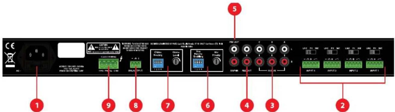
Fig. 2
1. NETWORK POWER SUPPLY INPUT with fuse housing
Connect the unit to the mains Power Supply 230/117V\~ 50/60Hz.
FUSE
100÷240 V\~ 50/60Hz Fuse: T2AL AC250V.
2. INPUT 1 ÷ INPUT 4
Balanced/unbalanced input on "Euroblock" connector.
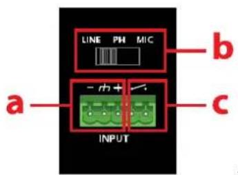
fig.3
The INPUT1, INPUT2, INPUT3 e INPUT4 inputs are of balanced/unbalanced type, used for the connection of low impedance dynamic microphones (30-600Ω), condenser microphones with 48V phantom power supply and audio sources with "line" level signal output (e.g. AM/FM tuner, cassette player, CD player, etc.).
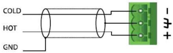
a) Connection of a Balanced line to the INPUT (fig.3, ref.a)
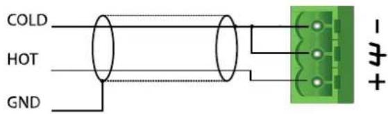
Connection of a Unbalanced line to the INPUT (fig.3, ref.a)
b) Use the selectors to choose the source type to connect (fig.3 ref.a):
LINE for AM/FM tuners, CD players etc.
PH for condenser microphones with +48V phantom power
MIC for dynamic microphones
c) "Dry Contact"
Each input has a "Dry Contact" that has the functions "Chime Activation" and "Force Input Muting". These functions can also be activated simultaneously and are subjected to the (ON - OFF) position of the dip switch (fig.2, ref.6 e 7):
"Chime Activation"
The amplifier will play an alert sound from the loudspeakers line when the contact is closed (fig.3 ref.C) with the relative dip-switch PIN ON (fig.2 rif.7).
"Force Input Muting"
The control forces the muting of AUX inputs and other inputs (fig.2, ref.2) with the relative VOX PIN (fig.2, ref.6) OFF when the contact is closed (fig.3 ref.C). Inputs will remain mute while the dry contact remains closed. This function is particularly useful with very weak audio signals, which may cause constant connections/disconnections of the VOX function, resulting in alternating the signal output.
Note: the dry contact will not mute the inputs that have VOX ON.
Each INPUT 1 ÷ INPUT 4 has a VOX function that can be switched on and off using the PIN (fig.2, ref.6): while the VOX circuit of one of the channels with VOX ON (enabled) detects the presence of an audio signal on the relative input (fig.2, ref.2), the AUX channels (fig.2, ref.3) and the channels with VOX OFF (disabled) will be muted, while all the channels with VOX ON will be mixed in the output.
3. AUX IN
The device has 3 AUX inputs that can be selected from the front panel (fig.1 ref.7):
The R and L sockets allow to connect the right (R) and left (L) channels through RCA connectors. You can connect to this stereo input an external sound source.
4. REC OUT
Unbalanced output line to be used for recording functions.
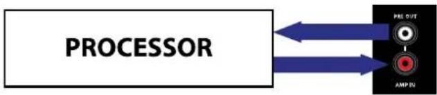
5. Input AMP IN - Output PRE OUT
flowchart
graph LR
    A["PROCESSOR"] --> B["PRE OUT"]
    A --> C["AMP IN"]
As a standard the AMP IN input is connected to the PRE OUT output with a jumper.
You can optimise the amplifying signal inserting an external unit (e.g. equaliser, processor, etc.) between the two terminals. For the connection check the drawing.
6. VOX PRIORITY ENABLING and MIC PRIORITY
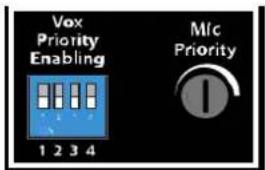
Vox Priority Enabling enables the VOX function on the relative INPUT 1 ÷ INPUT 4 inputs:
Examples:
ON-ON-ON-ON - Vox enabled on all inputs
ON-OFF-ON-OFF - Vox enabled on the 1 - 3 inputs and disabled on the 2 - 4 inputs
......
OFF-OFF-OFF-OFF - Vox disabled on all inputs
VOX operation
Each INPUT 1 ÷ INPUT 4 has a VOX function that can be switched on and off using the relative PIN (Vox Priority Enabling): when the VOX circuit of one of the channels with VOX ON (enabled) detects the presence of an audio signal on the relative input (fig.2, ref.2), the AUX channels (fig.2, ref.3) and the channels with VOX OFF (disabled) will be muted, while all the channels with VOX ON will be mixed in the output.
MIC PRIORITY
MIC PRIORITY function causes a signal present on the channels (INPUT 1 ÷ INPUT 4) with VOX active to reduce the level of all other inputs (AUX and INPUT with VOX OFF) of a value adjustable at will using the MIC PRIORITY trimmer
Note:
Adjusting the trimmer to Minimum (to the left), the AUX and with VOX OFF channels will be completely muted.
Adjusting the trimmer to Maximum (to the right) the Priority function will be bypassed and all the channels will be always active.
7. CHIME ROUTING and CHIME LEVEL
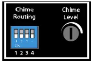
Chime Routing enables the Chime function on the relative INPUT 1 ÷ INPUT 4 inputs:
Examples:
ON-ON-ON-ON - CHIME enabled on all inputs
ON-OFF-ON-OFF - CHIME enabled on the 1 - 3 inputs and disabled on the 2 - 4 inputs
······
OFF-OFF-OFF-OFF - CHIME disabled on all inputs
The amplifier will play an alert sound from the loudspeakers line when the relative contact is closed (fig.3 ref.C) when CHIME is enabled on an input.
8. BAL OUTPUT
Balanced linking output with line level.
Use this output to send the AMP160XL input signal to another amplifier.
Note:
Balanced connection
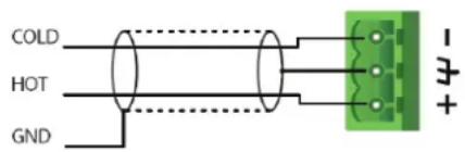
Unbalanced connection
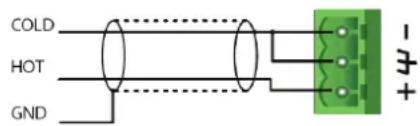
9. LOUDSPEAKERS OUTPUT
The device allows the connection of constant impedance speakers (4Ω) or constant voltage speakers at (70/100V). It is not possible to connect them mixed.
5. LOUDSPEAKER CONNECTION
Attention
To avoid the risk of electric shocks, never touch the amplifier outputs when they are operating.
The device can be used with loudspeakers having constant impedance (4Ω) as well as constant voltage (70V, 100V). Keep the following instructions in mind when carrying out connections.
Constant impedance line:
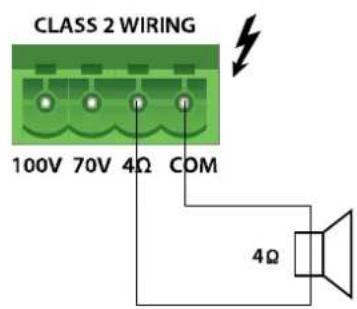
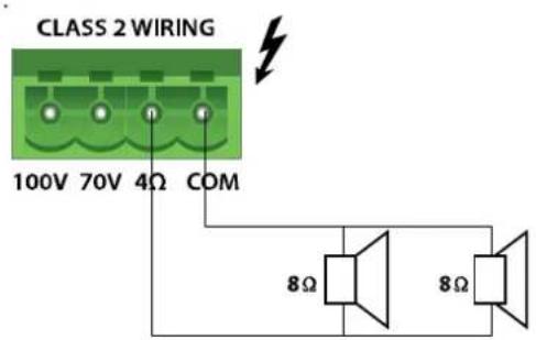
Connect the constant impedance line (4Ω) between the "COM" and "4Ω" terminals (Fig. 2, Ref. 4).
√ To ensure maximum performance, total impedance of the loudspeakers connected to the line must be equivalent to the output impedance of the amplifier.
√ The total power of the diffusers must not be less than the output power of the amplifier.
√ It is advisable to minimise the length of connection, and anyhow increase the cable section according to the distance covered.
Constant voltage line:
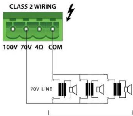
Connection to 100V or 70V
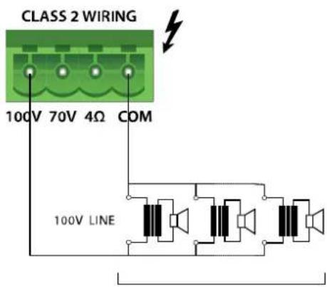
MAX. 160W
MAX. 160W
Connect the constant voltage line (100V or 70V) between the "COM" and "100V" (or "70V") terminals (Fig. 2, Ref. 4).
√ The loudspeakers must be supplied with a transformer having an input voltage equivalent to that of the amplifier.
√ The total power of the loudspeakers must not exceed the maximum output power of the amplifier.
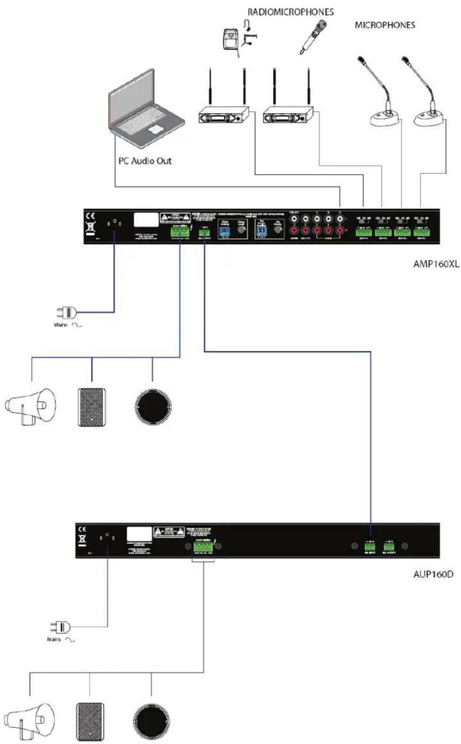
6. EXAMPLES OF POSSIBLE CONNECTIONS
flowchart
graph TD
    A["PC Audio Out"] --> B["AMP160XL"]
    B --> C["AUP160D"]
    C --> D["Mars"]
    C --> E["Main"]
    C --> F["Radio/Microphones"]
    C --> G["Microphones"]
    C --> H["Radiomicrophones"]
7. TECHNICAL SPECIFICATIONS
| Model: | AMP160XL |
| Output power RMS 160W | |
| Inputs | 4xMIC/LINE balanced3 AUX (selectable)1x MAIN IN (normally connected to PRE OUT) |
| Input Sensitivity | MIC: -40dBV / 600 Ω balanced (with 48Vphantom)LINE: 0dBV / 100 KΩ balancedAUX: 0dBV / 47 KΩ unbalancedMAIN IN: 0dBV / 10KΩ unbalanced |
| Signal Output | PRE OUT (normally connected to MAIN IN)PRE OUT: 1V / 600 ΩREC OUT: 1V / 600 ΩBAL OUTPUT:1V / 600 Ω |
| Controls | MASTER VOLUME CONTROL1 TREBLE TONE CONTROL1 BASS TONE CONTROL4 MIC/LINE VOLUME CONTROLS1 AUX VOLUME CONTROL |
| Loudspeakers outputs 100/70V/4Ω | |
| Frequency response | 80Hz -16KHz (-3dB) |
| Distortion (THD) | < 0.5% (@ Pnom 1KHz) |
| S/N Ratio | MIC: ≥70dBLINE: ≥70dBAUX: ≥80dB |
| Power Supply | autoswitch 100-240V~ 50/60Hz |
| Operating temperature | 0 -40°C |
| Input/Output Connectors | terminal blockRCA |
| Power Consumption | 160VA |
| Dimensions (LxHxP) (mm) | 439 x 44 x 278 mm483 x 44 x 278 mm - 1U rack19" |
| Weight (Kg) | 5 Kg |

8. CONTENTS OF THE PACKAGE
Amplifier
Rack adapters
Network power supply cable
Operating Manual
Proel SpA is committed to a constant research and development policy and therefore reserves the right to change and improve its products at any time without notice. REV.00 19/17


PROEL S.p.A.
(World Headquarters - Factory)
- POWER
- INSTRUCTIONS:
- Retain these instructions:
- Heed all warnings:
- Follow all instructions:
- DETAILED SAFETY INSTRUCTIONS.
- Water and moisture:
- Ventilation:
- Heat:
- Power sources:
- Grounding or Polarization:
- Power cable protection:
- Cleaning:
- No use periods:
- Objects or liquid entry into the unit:
- Safe power line use:
- Unit relocation:
- Do not open this unit:
- Damages requiring services:
- Maintenance:
- IMPORTANT SAFETY INSTRUCTIONS:
- DESCRIPTION
- MAIN FUNCTIONS:
- FRONT PANEL CONTROLS AND FUNCTIONS
- MASTER
- TREBLE
- BASS
- INPUT 1 ÷ INPUT 4
- AUX
- AUX input selector
- 1U 19" rack adapters
- REAR PANEL FUNCTIONS AND CONTROLS
- NETWORK POWER SUPPLY INPUT with fuse housing
- INPUT 1 ÷ INPUT 4
- AUX IN
- REC OUT
- Input AMP IN - Output PRE OUT
- VOX PRIORITY ENABLING and MIC PRIORITY
- Examples:
- VOX operation
- MIC PRIORITY
- CHIME ROUTING and CHIME LEVEL
- BAL OUTPUT
- LOUDSPEAKERS OUTPUT
- LOUDSPEAKER CONNECTION
- Attention
- Constant impedance line:
- Constant voltage line:
- EXAMPLES OF POSSIBLE CONNECTIONS
- TECHNICAL SPECIFICATIONS
- CONTENTS OF THE PACKAGE
- PROEL S.p.A.
Brand : Proel
Model : AMP160XL
Category : Receiver