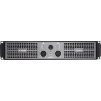
DPX2500PFC - Receiver Proel - Free user manual and instructions
Find the device manual for free DPX2500PFC Proel in PDF.


| Product Type | Professional Audio Receiver / Amplifier |
| Brand | Proel |
| Model | DPX2500PFC |
| Amplifier Class | Class D with PFC (Power Factor Correction) |
| Number of Channels | 2 |
| Power Output (per channel) | 1250 W RMS at 4 ohms, 800 W RMS at 8 ohms |
| Total Power Output | 2500 W RMS |
| Frequency Response | 20 Hz – 20 kHz (±1 dB) |
| Dimensions (W x H x D) | 483 x 88 x 400 mm (19", 2U) |
| Weight | 12 kg |
| Power Supply | 230 V ~ 50/60 Hz |
| Power Consumption | 3000 W maximum |
| Input Connectors | 3-pin XLR balanced |
| Output Connectors | Speakon NL4 |
| Cooling | Variable speed fan, front-to-rear airflow |
| Protection Features | Short circuit, thermal, overload, DC offset |
| Maintenance | Clean exterior with dry cloth; check fan filters monthly |
| Safety Precautions | Do not open chassis; operate in dry environment; disconnect power before cleaning |
| Spare Parts | Fuses (15A 250V 5x20mm), power supply module, fan |
| Repairability | Modular design; replaceable power supply and amplifier modules |
| Included Accessories | Power cord, rackmount ears, user manual |
| General Information | Professional grade amplifier for touring, installation, and live sound |
Frequently Asked Questions - DPX2500PFC Proel
User questions about DPX2500PFC Proel
0 question about this device. Answer the ones you know or ask your own.
Ask a new question about this device
Download the instructions for your Receiver in PDF format for free! Find your manual DPX2500PFC - Proel and take your electronic device back in hand. On this page are published all the documents necessary for the use of your device. DPX2500PFC by Proel.
USER MANUAL DPX2500PFC Proel
2 channel power amplifiers
USER MANUAL MANUALE D'USO
natural_image
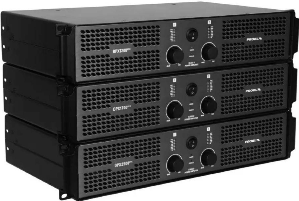
Three black industrial power amplifiers (DPX1200, DPX1700, DPX2500) with visible control knobs and ventilation grilles, no text or symbols on the equipment body.FCC COMPLIANCE NOTICE
This device complies with part 15 of the FCC rules. Operation is subject to the following two conditions:
(1) This device may not cause harmful interference, and
(2) this device must accept any interference received, including interference that may cause undesired operation.
CAUTION: Changes or modifications not expressly approved by the party responsible for compliance could void the user's authority to operate the equipment.
NOTE: This equipment has been tested and found to comply with the limits for a Class B digital device, pursuant to part 15 of the FCC Rules. These limits are designed to provide reasonable protection against harmful interference in a residential installation. This equipment generates, uses, and can radiate radio frequency energy and, if not installed and used in accordance with the instruction manual, may cause harmful interference to radio communications. However, there is no guarantee that interference will not occur in a particular installation. If this equipment does cause harmful interference to radio or television reception, which can be determined by turning the equipment off and on, the user is encouraged to try to correct the interference by one or more of the following measures:
- Reorient or relocate the receiving antenna.
- Increase the separation between the equipment and receiver.
- Connect the equipment into an outlet on a circuit different from that to which the receiver is connected.
- Consult the dealer or an experienced radio/TV technician for help.

This marking shown on the product or its literature, indicates that it should not be disposed with other household wastes at the end of its working life. To prevent possible harm to the environment or human health from uncontrolled waste disposal, please separate this from other types of wastes and recycle it responsibly to promote the sustainable reuse of material resources. Household users should contact either the retailer where they purchased this product, or their local government office, for details of where and how they can take this item for environmentally safe recycling. Business users should contact their supplier and check the terms and conditions of the
purchase contract. This product should not be mixed with other commercial wastes for disposal.
The lightning flash with arrowhead symbol within an equilateral triangle is intended to alert the user to the presence of uninsulated "dangerous voltage" within the product's enclosure, that may be of sufficient magnitude to constitute a risk of electric shock to persons.
The exclamation point within an equilateral triangle is intended to alert the user to the presence of important operating and maintenance (servicing) instructions in the literature accompanying the appliance.
The information contained in this publication has been carefully prepared and checked. However no responsibility will be taken for any errors. All rights are reserved and this document cannot be copied, photocopied or reproduced in part or completely without written consent being obtained in advance from PROEL. PROEL reserves the right to make any aesthetic, functional or design modification to any of its products without any prior notice. PROEL assumes no responsibility for the use or application of the products or circuits described herein.

SETUP AND RACK MOUNTING (FIG. 1) .....4
LOUDSPEAKER CABLE 4
CONNECTIONS 5
FILTER RESPONSE (FIG.2) 5
DIMENSIONS (FIG.3) 6
FRONT PANEL (FIG.4) 6
REAR PANEL (FIG.5) 7
EXAMPLE A 8
EXAMPLE B 8
EXAMPLE C....9
EXAMPLE D 9
SAFETY AND PRECAUTIONS.... 10
IN CASE OF FAULT 10
TROUBLESHOOTING 10
CE CONFORMITY.... 11
PACKAGING, SHIPPING AND COMPLAINT 11
WARRANTY AND PRODUCTS RETURN 11
INSTALLATION AND DISCLAIMER.... 11
POWER SUPPLY AND MAINTENANCE 11
GENERAL INFORMATION 12
INSTRUCTIONS 12
INDICE
SPECIFICHE TECNICHE ....3
SETUP AND RACK MOUNTING (FIG. 1) INSTALLAZIONE A RACK (FIG. 1)
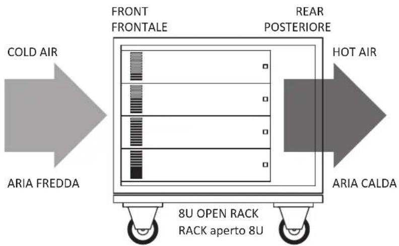
FIG.1
RECOMMENDED INSTALLATION
INSTALLAZIONE RACCOMANDATA
flowchart
graph LR
    A["COLD AIR"] --> B["ARIA FREDDA"]
    B --> C["FRONT FRONTALE"]
    C --> D["REAR POSTERIORE"]
    D --> E["HOT AIR"]
    E --> F["ARIA CALDA"]
    G["8U OPEN RACK RACK aperto 8U"] --> C
EVENTUAL INSTALLATION WITH CLOSED BACK
HOT AIR EVENTUALE INSTALLAZIONE CON RETRO CHIUSO

flowchart
graph TD
    A["ARIA CALDA"] --> B["FRONT FRONTALE"]
    B --> C["COLD AIR"]
    C --> D["ARIA FREDDA"]
    D --> E["10U closed RACK RACK chiuso 10U"]
    E --> F["15 cm 6 inch"]
    G["REAR (closed) POSTERIORE (chiuso)"] --> H["Vertical flow arrows"]
    H --> I["Vertical flow arrows"]
    I --> J["Vertical flow arrows"]
    J --> K["Vertical flow arrows"]
LOUDSPEAKER CABLE CAVO ALTOPARLANTE


ENGLISH: Loudspeaker Line Losses (maximum permissible line lengths for 0.5dB losses, voltage or spl)
| feet | meter | feet | meter | mm^2 | AWG | 2 wires | 4 wires | 2 wires Fire-resistant for fixed installation | 2 wires Fire-resistant with shielding |
| 75 | 25 | 150 | 50 | 4.0 | 12 | HPC624BK | HPC644 | HPC624FT(black) HPC624HT (blue) | HPC624FRS (green) |
| 50 | 17.5 | 100 | 35 | 2.0 | 14 | HPC620BK | HPC640BK | HPC620FT(black) HPC620HT (blue) | HPC620FRS (green) |
| 30 | 10 | 60 | 20 | 1.5 | 16 | HPC610BK | HPC610FT(black) HPC610HT (blue) | HPC610FRS (green) | |
| 20 | 7.5 | 40 | 15 | 1.0 | 18 | HPC600 |
this is a short extraction of the wide assortment of cables available from PROEL, please visit our website at www.proel.com
CONNECTIONS CONNESSIONI

INPUT
Balanced male XLR
INPUT (ingresso)
XLR bilanciato maschio

LINK
Balanced female XLR
natural_image
Cross-sectional diagram of a mechanical component with internal structure and mounting holes (no text or symbols)PROEL code - NL4FX
Codice PROEL - NL4FX
SPEAKER POWER OUTPUTS
POWER OUTPUT - uscite altoparlanti
Connettore per cavo tipo Speakon Neutrik NL4
Neutrik NL4 Speakon Cable Connector
OUTPUT 2

OUTPUT 1
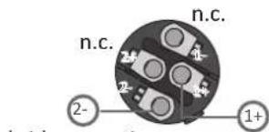
bridge positive

channel 2 negative
canale 2 negativo
OUTPUT 1
uscita 1BRIDGEuscita 2
channel 1 positive
canale 1 positivo
FILTER RESPONSE (FIG.2) RISPOSTA FILTRI (FIG.2)

line
| Frequency (Hz) | BI-AMP (CH1) (dB) | BI-AMP (CH2) (dB) | HPF (CH1-CH2) (dB) | | -------------- | ----------------- | ----------------- | ------------------ | | 2020K | 0 | 0 | -35 | | 5K | -5 | -5 | -35 | | 1K | -10 | -10 | -35 | | 2K | -15 | -15 | -35 | | 5K | -20 | -20 | -35 | | 10K | -25 | -25 | -35 | | 20K | -30 | -30 | -35 | | 50K | -35 | -35 | -35 | | 1K | -35 | -35 | -35 |DIMENSIONS (FIG.3) DIMENSIONI (FIG.3)

FRONT PANEL (FIG.4) PANNELLO FRONTALE (FIG.4)

REAR PANEL (FIG.5) PANNELLO POSTERIORE (FIG.5)

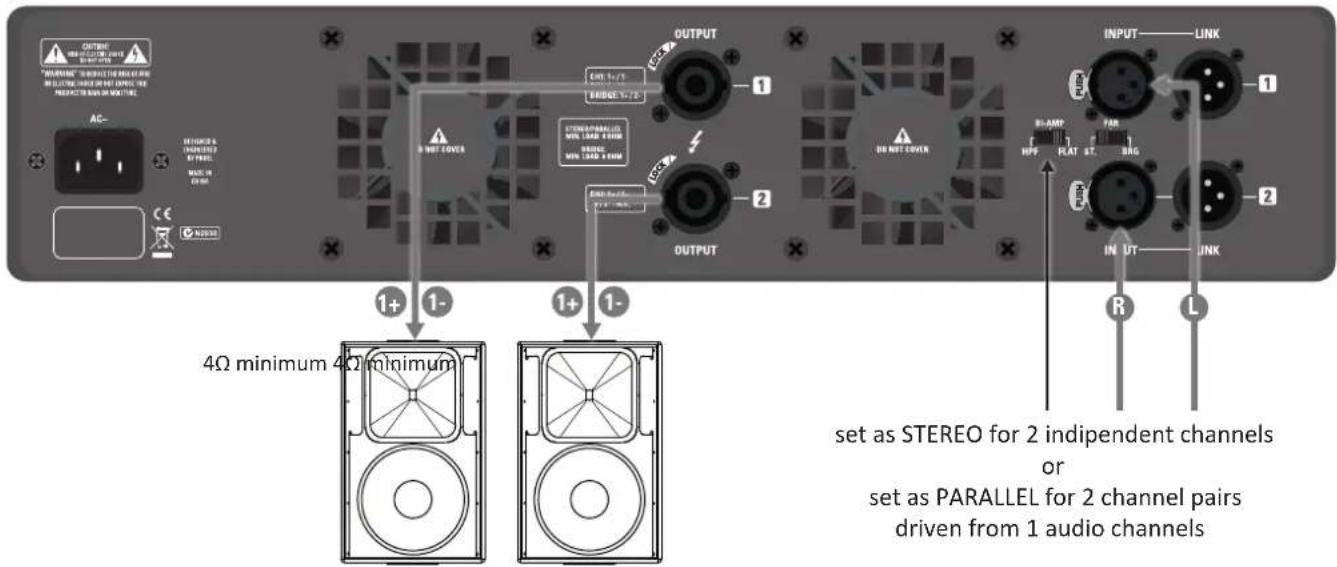
EXAMPLE A ESEMPIO A
EXAMPLE B ESEMPIO B
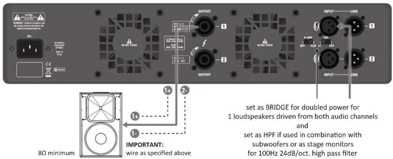
EXAMPLE C ESEMPIO C

EXAMPLE D ESEMPIO D

SAFETY AND PRECAUTIONS
- CAUTION: before using this product read carefully the following safety instructions. Take a look of this manual entirely and preserve it for future reference.
When using any electric product, basic precautions should always be taken, including the following:
- To reduce the risk, close supervision is necessary when the product is used near children.
- Protect the apparatus from atmospheric agents and keep it away from water, rain and high humidity places.
- This product should be site away from heat sources such as radiators, lamps and any other device that generate heat.
- This product should be located so that its location or position does not interfere with its proper ventilation and heating dissipation.
- Care should be taken so that objects and liquids do not go inside the product.
- The product should be connected to a power supply mains line only of the type described on the operating instructions or as marked on the product. Connect the apparatus to a power supply using only power cord included making always sure it is in good conditions.
- ⚠ WARNING: The mains plug is used as disconnect device, the disconnect device shall remain readily operable.
- Do not cancel the safety feature assured by means of a polarized line plug (one blade wider than the other) or with a earth connection.
- Make sure that power supply mains line has a proper earth connection.
- Power supply cord should be unplugged from the outlet during strong thunderstorm or when left unused for a long period of time.
- Do not place objects on the product's power cord or place it in a position where anyone could trip over, walk on or roll anything over it. Do not allow the product to rest on or to be installed over power cords of any type. Improper installations of this type create the possibility of fire hazard and/or personal injury.
- This product may be capable of producing sound levels that could cause permanent hearing loss. Exposure to extremely high noise levels may cause permanent hearing loss. Individuals vary considerably in susceptibility to noise-induced hearing loss, but nearly everyone will lose some hearing if exposed to sufficiently intense noise for a period of time. The U.S. Government's Occupational Safety and Health Administration (OSHA) has specified the permissible noise level exposures shown in the following chart. According to OSHA, any exposure in excess of these permissible limits could result in some hearing loss. To ensure against potentially dangerous exposure to high sound pressure levels, it is recommended that all persons exposed to equipment capable of producing high sound pressure levels use hearing protectors while the equipment is in operation. Ear plugs or protectors in the ear canals or over the ears must be worn when operating the equipment in order to prevent permanent hearing loss if exposure is in excess of the limits set forth here. Keep your's attention that children and pets are more susceptible to excessive noise levels.
| Duration Per DayIn Hours | Sound Level dBASlow Response | TypicalExample |
| 8 90 Duo in small club | ||
| $ 6 92 | ||
| 4 95 Subway Train | ||
| 3 97 | ||
| 2 100 Very loud classical music | ||
| 1.5 | 102 | |
| 1 105 Traffic noise | ||
| 0.5 | 110 | |
| 0.25 or less | 115 Loudest parts at a rock concert |
IN CASE OF FAULT
- In case of fault or maintenance this product should be inspected only by qualified service personnel when:
- There is a flaw either in the connections or in the supplied connecting cables.
– Liquids have spilled inside the product.
– The product has fallen and been damaged. - The product does not appear to operate normally or exhibits a marked change in performance.
– The product has been lost liquids or gases or the enclosure is damaged. - Do not operate on the product, it has no user-serviceable parts inside, refer servicing to an authorized maintenance centre.
TROUBLESHOOTING
| No Power • The amplifier's "POWER" switch is off.Make sure the mains AC outlet is live (check with a tester or a lamp).Make sure the mains plug is securely plugged into mains AC outlet. | |
| No Sound • Is the input | LEVEL control for the channel turned up?Is the SIGNAL LED illuminated? If not check if your signal level is too low or check the signal cable, mixer and other equipment setting and cabling.Are you sure your signal cables works properly? check it using a cable tester or replacing with a new one.Is the SPEAKON cable connector correctly inserted? turn it clockwise until it clicks.Are you sure your power cable works properly? check it using a cable tester or replacing with a new one. |
| Distorted Sound • Input | signal level is too high. Turn down your level controls.NOTE: The loudspeakers should never be operated at a level which causes the amplifier LIMIT LEDs to illuminate constantly. |
| Different channel level | Check if are using a balanced cable for one channel and an unbalanced one for the other, as this would cause a considerable difference in channel levels.Be sure that your loudspeaker system is fully connected and both loudspeakers have the same impedance. |
| Noise / Hum | Whenever possible, preferably use only balanced cables. Unbalanced lines may also be used but may result in noise over long cable runs, particularly if they runs together mains line.Sometimes it helps to plug all audio equipment into the same AC circuit so they share a common ground.Sometimes it helps to plug all audio equipment far away to other non audio equipment like lighting dimmers or refrigerators. |
| No Sound and the Amplifier gets too hot | The amplifier temperature protections trips, re-locate the amplifier in a more ventilated location. |
| No Sound and Protection trip(LED PROT always on) | Could be a possible short circuit at the amplifier loudspeakers outputs, the speaker’s inputs or in the cabling. Locate and remove the short circuit.The impedance of the loudspeakers connected is too low. Use a speaker with a minimum impedance of 4Ω (8Ω in the Bridge mode).If no load connected the protection trips the same, a DC voltage has been detected in the amplifier’s output circuit and you have to contact you nearest service assistance center to repair the amplifier. |
CE CONFORMITY
• Proel products comply with directive EMC 2014/30/CE, as stated in EN 55103-1 and EN 55103-2 standards and with directive LVD 2014/35/CE, as stated in EN 60065 standard.
- Under the EM disturbance, the ratio of signal-noise will be changed above 10dB.
PACKAGING, SHIPPING AND COMPLAINT
- This unit package has been submitted to ISTA 1A integrity tests. We suggest you control the unit conditions immediately after unpacking it.
- If any damage is found, immediately advise the dealer. Keep all unit packaging parts to allow inspection.
- Proel is not responsible for any damage that occurs during shipment.
- Products are sold "delivered ex warehouse" and shipment is at charge and risk of the buyer.
- Possible damages to unit should be immediately notified to forwarder. Each complaint for package tampered with should be done within eight days from product receipt.
WARRANTY AND PRODUCTS RETURN
• Proel products have operating warranty and comply their specifications, as stated by manufacturer.
- Proel warrants all materials, workmanship and proper operation of this product for a period of two years from the original date of purchase. If any defects are found in the materials or workmanship or if the product fails to function properly during the applicable warranty period, the owner should inform about these defects the dealer or the distributor, providing receipt or invoice of date of purchase and defect detailed description. This warranty does not extend to damage resulting from improper installation, misuse, neglect or abuse. Proel S.p.A. will verify damage on returned units, and when the unit has been properly used and warranty is still valid, then the unit will be replaced or repaired. Proel S.p.A. is not responsible for any "direct damage" or "indirect damage" caused by product defectiveness.
INSTALLATION AND DISCLAIMER
- Proel products have been expressly designed for audio application, with signals in audio range (20Hz to 20kHz). Proel has no liability for damages caused in case of lack of maintenance, modifications, improper use or improper installation non-applying safety instructions.
- These amplifiers are adapted in a properly ventilated, standard professional 19" rack. These units feature ventilation holes on the front and back panels. Absolutely do not obstruct the ventilation holes. Blocked ventilation can cause damages and fire.
- Do not locate sensitive high-gain equipment such as mixer, preamplifiers, recorders or AD/DA conversion units directly above or below these amplifiers. Because these amplifiers have a high power density, it has a strong magnetic field which can induce hum into unshielded devices that are located nearby. If an equipment rack is used, we recommend locating the amplifier in the bottom of the rack and the mixer, preamplifier or other sensitive equipment at the top.
- Proel S.p.A. reserves the right to change these specifications at any time without notice.
- Proel S.p.A. declines any liability for damages to objects or persons caused by lacks of maintenance, improper use, installation not performed with safety precautions and at the state of the art.
POWER SUPPLY AND MAINTENANCE
- Clean only with dry cloth.
- Check periodically that the slots for its proper ventilation and heating dissipation are not obstructed by dust, remove the dust using a dry brush or a compressed air gun.
- The DPX amplifiers of Proel have been designed with CLASS I construction and must be connected always to a mains socket outlet with a protective earth connection (the third grounding prong).
- Before connecting the product to the mains outlet make certain that the mains line voltage matches that shown on the rear of the product, a tolerance of up to ± 10% is acceptable.
• To disconnect these equipment from the AC Mains, disconnect the power supply cord plug from the AC receptacle.
• THE REPLACEMENT OF FUSES INSIDE THE APPARATUS MUST BE MADE ONLY BY QUALIFIED PERSONNEL. - CHECK THE CONDITION OF THE PROTECTION FUSE, ACCESSIBLE OUTWARD, ONLY WITH THE APPARATUS SWITCHED OFF AND DISCONNECTED FROM THE MAINS LINE OUTLET.
- REPLACE THE PROTECTION FUSE ONLY WITH SAME TYPE AS SHOWN ON THE PRODUCT.
- IF AFTER THE SUBSTITUTION, THE FUSE INTERRUPTS AGAIN THE APPARATUS WORKING, DO NOT TRY AGAIN THEN CONTACT THE PROEL SERVICE CENTRE.
GENERAL INFORMATION
Thank you for having chosen a PROEL product.
DPX PFC is a series of ultra-lightweight power amplifiers able to provide, for professional mobile and fixed PA systems, a huge amount of power and the maximum performance and portability in a very affordable package.
Thanks to the high-density Class D technology employed in the output stages, we've been able to build very powerful amplifiers in an ultra-compact and lightweight package. The extremely efficient Switch Mode Power Supply (SMPS) with Power Factor Correction technology (PFC) helps to reduce further the weight and provides universal mains operation, delivering constant energy to the loudspeakers regardless of the AC line voltage fluctuations and eliminating the need for market specific power supplies and related reliability issues.
All models feature a built-in 24dB/octave stereo crossover with BI-AMP and HIGH-PASS options, for easily filtering a 2-way system without the need of additional outboard. Fast-attack precise CLIP LIMITERS guarantee maximum output without distortion, while a comprehensive protection system safeguards both the speakers and the amplifier.
The electronics is hosted in a feather-light all-aluminum case, able to provide an efficient cooling and, at the same time, protection and durability over the years.
DPX PFC are power amplifiers offering extraordinary value to professional entertainers, DJ and sound engineers looking for massive output, excellent performance and absolute portability.
INSTRUCTIONS
1. Power switch
Amplifier is "ON" when the switch is in the "I" position.
2. Power indicator
Green LED: when lighted indicates amplifier has been turned on and AC power is available.
3. Channel LEVEL Control
Rotary level control: in STEREO and PARALLEL operation it attenuates the level of the signal sent to the correspondent channel of the amplifier, while in BRIDGE operation the channel control 1 operates as single control for the channel pair set as bridge.
The attenuation ranges from "-80dB" fully closed (the signal is completely attenuated) to "0" fully open, nominal level (the signal is not attenuated in any way, so is fed to the amplifier channel at the same level at which it arrives on input).
4. Channel SIGNAL METER Indicator
These are five green LED those indicate the presence and the level of the signal at the correspondent amplifier channel input.
5. Channel LIMIT Indicator
Red LED illuminates when the channel's output is limited. When this LED flashes reduce the input signal level.
6. Channel PROTECT Indicator
Red LED illuminates when the correspondent channel is in protect mode for one of the following reasons:
- The heatsink reaches a temperature above the normal working limit.
- There is a short circuit at the amplifier output wires.
- The amplifier output stages are faulty.
Consequently the channel is muted until the reason of fault is removed.
7. BRIDGE mode indicator
Yellow LED illuminates when the channel pair is in bridge mode.
NOTE: When the channel pair operates in BRIDGE mode SIGNAL, LIMIT and PROTECT LED indicators illuminate simultaneously, the signal is sent to the channel 1 input only and controlled by channel 1 level control only.
8. PARALLEL mode indicator
Yellow LED illuminates when the channel pair is in parallel mode.
NOTE: When the channel pair operates in PARALLEL mode the signal is sent to the channel 1 input only and controlled by channel 1 and channel 2 level controls for the respective amplifier channel, the SIGNAL, LIMIT and PROTECT LED indicators illuminate correspondingly.
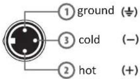
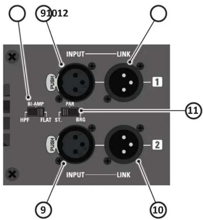
9. INPUT
This is a female XLR connector, which accepts a XLR plug from almost any type of equipment with a balanced or unbalanced outputs. The XLR input is wired as follows:
Pin 1 = shield or ground
Pin 2 = + positive or "hot"
Pin 3 = - negative or "cold"
When connecting an unbalanced signal, wire them as follows:
Pin2 = + positive or "hot"
Pin 1-3 = shield or ground
NOTE: whenever possible, use always balanced cables. Unbalanced lines may also be used but may result in noise over long cable runs. In any case, avoid using a balanced cable for one channel and an unbalanced one for the other.
10. LINK
This is a male XLR connector, it is connected in parallel with the respective INPUT, so the LINK is wired at the same way.
11. STEREO / PARALLEL / BRIDGE
Allows the selection of STEREO, PARALLEL or BRIDGE mode operations.
- In STEREO mode each amplifier channel pair runs independently driven by respective input (see EXAMPLE A).
- In PARALLEL mode both amplifier channels pair run together driven by Channel 1 input (see EXAMPLE A, D).
NOTE: use this setting if your intention is to use the BI-AMP feature also.
- In BRIDGE mode the amplifier channels pair runs together but with channel 1 in phase and channel 2 out of phase. The channels pairs are driven by Channel 1 input and the output must be taken from "OUTPUT 1" speakon output (see EXAMPLE B, C).
IMPORTANT: In this case a custom cable must be used wired as follows: at the amplifier side it must be wired 1+ for positive terminal and 2- for the negative terminal, at the speaker side the cable must be wired as usual 1+ for positive terminal and 1- for the negative terminal.
12. HPF / BI-AMP / FLAT
This switch allows the selection of one of the following filter configurations:
- HPF: enables a 100Hz LR-24dB/Oct. High Pass Filter for both channels 1 and 2: this a useful feature for SAT-TOP SPEAKERS or STAGE-MONITORS (see EXAMPLE B).
NOTE: when using HPF in combination with BRIDGE mode operation, the signal sent to the loudspeaker is only the high frequency band to be used for a SAT-TOP SPEAKER that operates in conjunction with a subwoofer.
- BI-AMP: enables a Linkwitz-Riley crossover 24dB/Oct. at 100Hz between channel 1 and channel 2, then allows a single amplifier without a dedicated processor to drive a SUB-WOOFER with channel 1 and a SAT-TOP SPEAKER with channel 2 (see EXAMPLE C, D).
NOTE: when using BI-AMP in combination with BRIDGE mode operation, the signal sent to the loudspeaker is only the low frequency band to be used for a SUB-WOOFER.
- FLAT: no filters are inserted in the signal path (see EXAMPLE A).
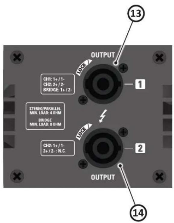
13. Channel 1 SPEAKON output
Accepts a female Neutrik Speakon NL4FX connector wired in this way:
• PIN 1+ connected to POSITIVE output of Channel 1;
• PIN 1- connected to NEGATIVE output of Channel 1;
• PIN 2+ connected to POSITIVE output of Channel 2,
• PIN 2- connected to NEGATIVE output of Channel 2,
If you connect a standard 2 wire cable (1+/1-), you run to the speaker the amplified output of the signal applied to channel 1 input.
If you connect a standard 4 wire cable (1+/1-/2+/2-), you run to the speaker:
- with amplifier set in STEREO mode, the amplified outputs of the signal applied to channel 1 input (1+/1-) and to channel 2 input (2+/2-),
- with amplifier set in PARALLEL mode, the amplified outputs of the signal applied to channel 1 input only, (1 + / 1 - ) = (2 + / 2 - ) ,
In both modes using a single cable you can connect a BI-AMP loudspeaker or a SUB-SAT speaker system. Always connect a loudspeaker with a minimum impedance of 4 ohm or more.
- With amplifier set in BRIDGE mode, you run to the speaker the amplified output of the signal applied to channel
1 input only, but the speakon cable must be custom wired as follows: at the amplifier side it must be wired 1+ for positive terminal and 2- for the negative terminal, at the speaker side the cable must be wired as usual 1+ for positive terminal and 1- for the negative terminal.
Always connect a loudspeaker with a minimum impedance of 8 ohm or more.
NOTE: Use only loudspeaker cables, never signal cables, i.e. those normally used for microphones, instruments and audio equipment in general.
14. Channel 2 SPEAKON output
Accepts a female Neutrik Speakon NL4FX connector wired in this way:
• PIN 1+ connected to POSITIVE output of Channel 2;
• PIN 1- connected to NEGATIVE output of Channel 2;
• PIN 2+ and 2- NOT connected.
This is the amplified output of the signal applied to channel 2 input if the amplifier is set in STEREO mode or the signal applied to channel 1 input if the amplifier is set in PARALLEL mode.
Always connect a loudspeaker with a minimum impedance of 4 ohm or more.
15. Fan
Fan Air cooling vent: always keep it clear of cables or other objects.
16. AC\~ SOCKET
Here's where you plug in your mains supply cord. You should always use the mains cord supplied with the device. Be sure that your device is turned off before you plug the mains supply cord into an electrical outlet.
AVVERTENZE PER LA SICUREZZA


- FCC COMPLIANCE NOTICE
- CAUTION: Changes or modifications not expressly approved by the party responsible for compliance could void the user's authority to operate the equipment.
- INDICE
- SETUP AND RACK MOUNTING (FIG. 1) INSTALLAZIONE A RACK (FIG. 1)
- LOUDSPEAKER CABLE CAVO ALTOPARLANTE
- CONNECTIONS CONNESSIONI
- FILTER RESPONSE (FIG.2) RISPOSTA FILTRI (FIG.2)
- EXAMPLE A ESEMPIO A
- EXAMPLE B ESEMPIO B
- EXAMPLE C ESEMPIO C
- EXAMPLE D ESEMPIO D
- SAFETY AND PRECAUTIONS
- IN CASE OF FAULT
- CE CONFORMITY
- PACKAGING, SHIPPING AND COMPLAINT
- WARRANTY AND PRODUCTS RETURN
- INSTALLATION AND DISCLAIMER
- POWER SUPPLY AND MAINTENANCE
- GENERAL INFORMATION
- INSTRUCTIONS
- Power switch
- Power indicator
- Channel LEVEL Control
- Channel SIGNAL METER Indicator
- Channel LIMIT Indicator
- Channel PROTECT Indicator
- BRIDGE mode indicator
- PARALLEL mode indicator
- INPUT
- LINK
- STEREO / PARALLEL / BRIDGE
- HPF / BI-AMP / FLAT
- Channel 1 SPEAKON output
- Channel 2 SPEAKON output
- Fan
- AC\~ SOCKET
- AVVERTENZE PER LA SICUREZZA
Brand : Proel
Model : DPX2500PFC
Category : Receiver